JP4804716B2 - Multi-wavelength read head for use in measuring analytes in body fluids - Google Patents
Multi-wavelength read head for use in measuring analytes in body fluids Download PDFInfo
- Publication number
- JP4804716B2 JP4804716B2 JP2004033124A JP2004033124A JP4804716B2 JP 4804716 B2 JP4804716 B2 JP 4804716B2 JP 2004033124 A JP2004033124 A JP 2004033124A JP 2004033124 A JP2004033124 A JP 2004033124A JP 4804716 B2 JP4804716 B2 JP 4804716B2
- Authority
- JP
- Japan
- Prior art keywords
- light
- sample
- read head
- light guide
- emitting elements
- Prior art date
- Legal status (The legal status is an assumption and is not a legal conclusion. Google has not performed a legal analysis and makes no representation as to the accuracy of the status listed.)
- Expired - Fee Related
Links
Images


Classifications
-
- A—HUMAN NECESSITIES
- A61—MEDICAL OR VETERINARY SCIENCE; HYGIENE
- A61B—DIAGNOSIS; SURGERY; IDENTIFICATION
- A61B5/00—Measuring for diagnostic purposes; Identification of persons
- A61B5/145—Measuring characteristics of blood in vivo, e.g. gas concentration, pH value; Measuring characteristics of body fluids or tissues, e.g. interstitial fluid, cerebral tissue
- A61B5/1455—Measuring characteristics of blood in vivo, e.g. gas concentration, pH value; Measuring characteristics of body fluids or tissues, e.g. interstitial fluid, cerebral tissue using optical sensors, e.g. spectral photometrical oximeters
-
- A—HUMAN NECESSITIES
- A61—MEDICAL OR VETERINARY SCIENCE; HYGIENE
- A61B—DIAGNOSIS; SURGERY; IDENTIFICATION
- A61B5/00—Measuring for diagnostic purposes; Identification of persons
- A61B5/145—Measuring characteristics of blood in vivo, e.g. gas concentration, pH value; Measuring characteristics of body fluids or tissues, e.g. interstitial fluid, cerebral tissue
- A61B5/14532—Measuring characteristics of blood in vivo, e.g. gas concentration, pH value; Measuring characteristics of body fluids or tissues, e.g. interstitial fluid, cerebral tissue for measuring glucose, e.g. by tissue impedance measurement
-
- G—PHYSICS
- G01—MEASURING; TESTING
- G01N—INVESTIGATING OR ANALYSING MATERIALS BY DETERMINING THEIR CHEMICAL OR PHYSICAL PROPERTIES
- G01N21/00—Investigating or analysing materials by the use of optical means, i.e. using sub-millimetre waves, infrared, visible or ultraviolet light
- G01N21/17—Systems in which incident light is modified in accordance with the properties of the material investigated
- G01N21/25—Colour; Spectral properties, i.e. comparison of effect of material on the light at two or more different wavelengths or wavelength bands
- G01N21/255—Details, e.g. use of specially adapted sources, lighting or optical systems
-
- G—PHYSICS
- G01—MEASURING; TESTING
- G01N—INVESTIGATING OR ANALYSING MATERIALS BY DETERMINING THEIR CHEMICAL OR PHYSICAL PROPERTIES
- G01N21/00—Investigating or analysing materials by the use of optical means, i.e. using sub-millimetre waves, infrared, visible or ultraviolet light
- G01N21/17—Systems in which incident light is modified in accordance with the properties of the material investigated
- G01N21/47—Scattering, i.e. diffuse reflection
- G01N21/4738—Diffuse reflection, e.g. also for testing fluids, fibrous materials
- G01N21/474—Details of optical heads therefor, e.g. using optical fibres
-
- G—PHYSICS
- G01—MEASURING; TESTING
- G01N—INVESTIGATING OR ANALYSING MATERIALS BY DETERMINING THEIR CHEMICAL OR PHYSICAL PROPERTIES
- G01N21/00—Investigating or analysing materials by the use of optical means, i.e. using sub-millimetre waves, infrared, visible or ultraviolet light
- G01N21/17—Systems in which incident light is modified in accordance with the properties of the material investigated
- G01N21/47—Scattering, i.e. diffuse reflection
- G01N21/49—Scattering, i.e. diffuse reflection within a body or fluid
-
- G—PHYSICS
- G01—MEASURING; TESTING
- G01N—INVESTIGATING OR ANALYSING MATERIALS BY DETERMINING THEIR CHEMICAL OR PHYSICAL PROPERTIES
- G01N21/00—Investigating or analysing materials by the use of optical means, i.e. using sub-millimetre waves, infrared, visible or ultraviolet light
- G01N21/84—Systems specially adapted for particular applications
- G01N21/8483—Investigating reagent band
-
- G—PHYSICS
- G01—MEASURING; TESTING
- G01N—INVESTIGATING OR ANALYSING MATERIALS BY DETERMINING THEIR CHEMICAL OR PHYSICAL PROPERTIES
- G01N21/00—Investigating or analysing materials by the use of optical means, i.e. using sub-millimetre waves, infrared, visible or ultraviolet light
- G01N21/17—Systems in which incident light is modified in accordance with the properties of the material investigated
- G01N21/25—Colour; Spectral properties, i.e. comparison of effect of material on the light at two or more different wavelengths or wavelength bands
- G01N21/31—Investigating relative effect of material at wavelengths characteristic of specific elements or molecules, e.g. atomic absorption spectrometry
- G01N21/314—Investigating relative effect of material at wavelengths characteristic of specific elements or molecules, e.g. atomic absorption spectrometry with comparison of measurements at specific and non-specific wavelengths
- G01N2021/3148—Investigating relative effect of material at wavelengths characteristic of specific elements or molecules, e.g. atomic absorption spectrometry with comparison of measurements at specific and non-specific wavelengths using three or more wavelengths
-
- G—PHYSICS
- G01—MEASURING; TESTING
- G01N—INVESTIGATING OR ANALYSING MATERIALS BY DETERMINING THEIR CHEMICAL OR PHYSICAL PROPERTIES
- G01N21/00—Investigating or analysing materials by the use of optical means, i.e. using sub-millimetre waves, infrared, visible or ultraviolet light
- G01N21/17—Systems in which incident light is modified in accordance with the properties of the material investigated
- G01N21/25—Colour; Spectral properties, i.e. comparison of effect of material on the light at two or more different wavelengths or wavelength bands
- G01N21/31—Investigating relative effect of material at wavelengths characteristic of specific elements or molecules, e.g. atomic absorption spectrometry
- G01N21/314—Investigating relative effect of material at wavelengths characteristic of specific elements or molecules, e.g. atomic absorption spectrometry with comparison of measurements at specific and non-specific wavelengths
- G01N2021/3181—Investigating relative effect of material at wavelengths characteristic of specific elements or molecules, e.g. atomic absorption spectrometry with comparison of measurements at specific and non-specific wavelengths using LEDs
-
- G—PHYSICS
- G01—MEASURING; TESTING
- G01N—INVESTIGATING OR ANALYSING MATERIALS BY DETERMINING THEIR CHEMICAL OR PHYSICAL PROPERTIES
- G01N21/00—Investigating or analysing materials by the use of optical means, i.e. using sub-millimetre waves, infrared, visible or ultraviolet light
- G01N21/75—Systems in which material is subjected to a chemical reaction, the progress or the result of the reaction being investigated
- G01N21/77—Systems in which material is subjected to a chemical reaction, the progress or the result of the reaction being investigated by observing the effect on a chemical indicator
- G01N21/78—Systems in which material is subjected to a chemical reaction, the progress or the result of the reaction being investigated by observing the effect on a chemical indicator producing a change of colour
-
- G—PHYSICS
- G01—MEASURING; TESTING
- G01N—INVESTIGATING OR ANALYSING MATERIALS BY DETERMINING THEIR CHEMICAL OR PHYSICAL PROPERTIES
- G01N2201/00—Features of devices classified in G01N21/00
- G01N2201/06—Illumination; Optics
- G01N2201/062—LED's
- G01N2201/0627—Use of several LED's for spectral resolution
Landscapes
- Health & Medical Sciences (AREA)
- Life Sciences & Earth Sciences (AREA)
- Physics & Mathematics (AREA)
- General Health & Medical Sciences (AREA)
- Pathology (AREA)
- Chemical & Material Sciences (AREA)
- Analytical Chemistry (AREA)
- Biochemistry (AREA)
- General Physics & Mathematics (AREA)
- Immunology (AREA)
- Molecular Biology (AREA)
- Medical Informatics (AREA)
- Surgery (AREA)
- Biophysics (AREA)
- Engineering & Computer Science (AREA)
- Biomedical Technology (AREA)
- Heart & Thoracic Surgery (AREA)
- Optics & Photonics (AREA)
- Veterinary Medicine (AREA)
- Public Health (AREA)
- Animal Behavior & Ethology (AREA)
- Spectroscopy & Molecular Physics (AREA)
- Emergency Medicine (AREA)
- Investigating Or Analysing Materials By Optical Means (AREA)
- Investigating Or Analysing Materials By The Use Of Chemical Reactions (AREA)
Description
本発明は一般に、生物学的サンプル中の分析対象物の濃度を測定するための試験システムに関し、より具体的には、生物学的サンプル中の分析対象物の濃度を測定する際に使用するための光学読み取りヘッドに関する。 The present invention relates generally to test systems for measuring the concentration of an analyte in a biological sample, and more specifically for use in measuring the concentration of an analyte in a biological sample. The present invention relates to an optical read head.
血液サンプルを速やかに採取し、血液サンプルの分析を実施することがしばしば必要である。血液サンプルを採取する必要性の一例は、使用者が自らの血中グルコースレベルをモニタリングするためにしばしば使用しなければならない血中グルコースモニタリングシステムに関連する。 It is often necessary to take a blood sample quickly and perform an analysis of the blood sample. One example of the need to take a blood sample relates to a blood glucose monitoring system that a user must often use to monitor their blood glucose level.
不規則な血中グルコース濃度レベルを有する人は、医療上、自らの血中グルコース濃度レベルを規則的に自己モニタリングすることを求められる。不規則な血中グルコースレベルは、糖尿病のような疾病をはじめとする多様な理由によって起こり得る。血中グルコース濃度レベルをモニタリングする目的は、血中グルコース濃度レベルを測定したのち、そのレベルが高すぎるか低すぎるかに基づき、是正措置を講じて、レベルを正常範囲内に戻すためである。是正措置を講じることができないと、深刻な事態が暗示される。血中グルコースレベルが低下しすぎると(低血糖症として知られる症状)、神経質になり、震え、混乱する。その人の判断力は損なわれ、最終的には失神することもある。また、血中グルコースレベルが上昇しすぎるならば(高血糖症として知られる症状)、非常に重症になる。低血糖症及び高血糖症のいずれも、潜在的に生命を脅かす緊急事態である。 Persons with irregular blood glucose concentration levels are medically required to regularly self-monitor their blood glucose concentration levels. Irregular blood glucose levels can occur for a variety of reasons, including diseases such as diabetes. The purpose of monitoring the blood glucose concentration level is to measure the blood glucose concentration level and then take corrective action to bring the level back into the normal range based on whether the level is too high or too low. If corrective action cannot be taken, a serious situation is implied. If blood glucose levels fall too low (a condition known as hypoglycemia), they become nervous, trembling, and confused. The person's judgment is impaired and eventually faints. Also, if the blood glucose level rises too much (a symptom known as hyperglycemia), it becomes very severe. Both hypoglycemia and hyperglycemia are potentially life threatening emergencies.
人の血中グルコースレベルをモニタリングする一つの方法は、手のひらサイズの携帯型血中グルコース試験装置を用いる方法である。このような装置の携帯性は、使用者が、どこに居ようとも、自らの血中グルコースレベルを簡便に試験することを可能にする。通常、これらの装置は、電気化学的試験又は比色試験のいずれかを用いることができる。電気化学的検定では、試薬が、血液中のグルコースと反応して、反応区域内に配置された電極で酸化電流を発生させるように設計されている。この電流は、使用者の血液中のグルコースの濃度に正比例する。比色検定では、試薬は、使用者の血中グルコース濃度レベルを示す比色反応を生じさせるように設計されている。すると、試験装置に組み込まれた光学計器が比色反応を読み取る。 One method for monitoring a person's blood glucose level is to use a hand-held portable blood glucose test device. The portability of such a device allows the user to conveniently test their blood glucose level wherever they are. Typically, these devices can use either electrochemical tests or colorimetric tests. In an electrochemical assay, the reagent is designed to react with glucose in the blood and generate an oxidation current at an electrode placed in the reaction zone. This current is directly proportional to the concentration of glucose in the user's blood. In a colorimetric assay, the reagent is designed to produce a colorimetric reaction that is indicative of the user's blood glucose concentration level. The optical instrument incorporated in the test apparatus then reads the colorimetric response.
比色反応を読み取るための光学計器に伴う欠点は、サイズ、低い信号スループット及び一部には光学部品の機械的アライメント(又はミスアライメント)感度による精度誤差を含む。光学計器が二以上の波長での読み取りを要する場合、これらの問題はさらに複合化する。多数の波長を設けることは、従来技術の装置が、発光ダイオードのような異なる発光素子で各波長の光を生成するため、これらの問題を複合化する。多数の発光ダイオードを整列させてサンプル区域の同一の照射を提供することは困難であり、費用を要する。ミスアライメント及び光源の形状寸法の変化は、各発光ダイオードからの光が異なる放射照度及びサンプル上での異なる放射照度分布を有する結果をもたらす。したがって、必要とされるものは、複数の波長の光でサンプルを照射することができる装置であって、異なる波長の各光束が実質的に均一な放射照度及びサンプル上での放射照度分布を有する装置である。 Disadvantages associated with optical instruments for reading colorimetric responses include size, low signal throughput, and accuracy errors due in part to the mechanical alignment (or misalignment) sensitivity of optical components. These problems are further compounded when the optical instrument requires reading at more than one wavelength. Providing multiple wavelengths complicates these problems because prior art devices generate light of each wavelength with different light emitting elements such as light emitting diodes. It is difficult and expensive to align multiple light emitting diodes to provide the same illumination of the sample area. Misalignment and light source geometry changes result in the light from each light emitting diode having different irradiance and different irradiance distribution on the sample. Therefore, what is needed is an apparatus that can illuminate a sample with multiple wavelengths of light, where each beam of different wavelengths has a substantially uniform irradiance and irradiance distribution on the sample. Device.
サンプル中の分析対象物の濃度の測定に使用するための読み取りヘッドは、サンプルを受けるための読み取り区域と、複数の波長の光を出力するための複数の発光素子を含む光源と、入力端及び出力端を有する導光体と、導光体の出力端から光を受け、実質的に平行にされた光束でサンプルを照射するためのレンズと、サンプルの照射に応答してサンプルからの光を検出するための検出器とを含む。導光体の入力端は、複数の発光素子によって出力される光を受けるために光源に光学的に結合されている。導光体の入力端は、複数の発光素子の少なくとも1個の中心から偏心している中心を有する。導光体は、光源から受けた光の実質的部分を導光体の出力端に誘導する。 A read head for use in measuring the concentration of an analyte in a sample includes a read area for receiving the sample, a light source including a plurality of light emitting elements for outputting light of a plurality of wavelengths, an input end, and A light guide having an output end, a lens for receiving light from the output end of the light guide and irradiating the sample with a substantially collimated light beam, and light from the sample in response to the sample irradiation. And a detector for detecting. The input end of the light guide is optically coupled to a light source to receive light output by the plurality of light emitting elements. The input end of the light guide has a center that is eccentric from the center of at least one of the plurality of light emitting elements. The light guide guides a substantial portion of the light received from the light source to the output end of the light guide.
本発明の上記概要は、本発明の各実施態様又はあらゆる側面を表すことを意図するものではない。詳細な説明、図面及び特許請求の範囲から、本発明のさらなる特徴及び利点が、詳細な記述、図面及び請求の範囲から明らかになるであろう。 The above summary of the present invention is not intended to represent each embodiment or every aspect of the present invention. Further features and advantages of the invention will be apparent from the detailed description, drawings, and claims from the detailed description, drawings, and claims.
本発明は、種々の変形及び代替形態を受けることができるが、具体的な実施態様を図面で一例として示し、本明細書で詳細に説明する。しかし、本発明は、開示される特定の形態に限定されることを意図しないことを理解すべきである。それどころか、本発明は、特許請求の範囲によって定義される発明の本質及び範囲に当てはまるすべての変形、均等及び代替を包含する。 While the invention is susceptible to various modifications and alternative forms, specific embodiments are shown by way of example in the drawings and are described in detail herein. However, it should be understood that the invention is not intended to be limited to the particular forms disclosed. On the contrary, the invention encompasses all modifications, equivalents and alternatives falling within the spirit and scope of the invention as defined by the claims.
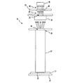
図面、まず図1を参照すると、本発明の一つの実施態様の多重波長読み取りヘッド10が示されている。一つの用途では、読み取りヘッド10は、患者(自己試験用途の場合の使用者でもある)の体液中のグルコース濃度を計測するための手の中におさまるサイズの携帯型グルコース試験装置に含まれる。具体的には、読み取りヘッド10は、試薬が分析対象物と反応したときの比色反応を計測するために使用される。本発明の読み取りヘッド10は、反応から生じる試薬の変色の程度の計測に使用される。試薬の変色の程度は、体液中の分析対象物(たとえばグルコース、フルクトサミン、ヘモグロビンA1c、コレステロールなど)の濃度を示す。比色試験は、全体を引用例として本明細書に取り込む「Control Solution and Method for Testing the Performance of an Electrochemical Device for Determining the Concentration of an Analyte in Blood」と題する米国特許第5,723,284号に詳細に記載されている。比色試験はまた、いずれも全体を引用例として本明細書に取り込む米国特許第6,181,417B1号(「Photometric Readhead with Light Plate」と題する)、第5,518,689号(「Diffuse Light Reflectance Readhead」と題する)及び第5,611,999号(「Diffuse Light Reflectance Readhead」と題する)で詳細に記載されている。
Referring now to the drawings, and first to FIG. 1, a multiple wavelength read
本発明の一つの実施態様によると、読み取りヘッド10は、表面取り付け発光ダイオード(「SMD LED」)12を含む光源を含む。SMD LED12は、本発明の読み取りヘッド10が含まれる装置を作動させる電子系を含むことができるプリント回路板(「PCB」)14に取り付けられている。SMD LED12は、複数の波長の光、たとえば赤、緑及び青の光を出力する多重波長SMD LEDである。一つの実施態様によると、表面取り付け装置は、約600nm〜約670nmの範囲の波長を有する赤色光を出力するための赤色LED、約520nm〜約580nmの範囲の波長を有する緑色光を出力するための緑色LED、及び約360nm〜450nmの範囲の波長を有するの青色光を出力するための青色LEDを含む。もう一つの実施態様によると、赤色光は約625nmの波長を有し、緑色光は約565nmの波長を有し、青色光は約430nmの波長を有する。本発明のさらに別の代替態様によると、表面取り付け装置は、約800nm〜約1000nmの範囲の波長を有する赤外線を出力するための赤外線LEDを含む。読み取りヘッド10とで使用するのに適したSMD LEDは、米カリフォルニア州City of IndustryのKingbright社から市販されている(型番AAA3528EMBSGC)。代替態様によると、光源は、LED以外のタイプの光源を含むこともできる。たとえば、多数のパッケージ化LED、多数のチップ・オン・ボードLED又はレーザダイオードを、複数の波長の光を出力するための光源として使用することができる。
In accordance with one embodiment of the present invention, the read
以下さらに詳細に記載するように、SMD LED12によって出力される光の多重波長がサンプルを照射する。干渉し合う波長を使用して、サンプルを評価するために使用される特定の波長の誤差を修正することができるので、計器の性能は、多重波長の光でサンプルを照射することによって改善される。たとえば、サンプルが血液である場合、ヘモグロビンのような、生来のクロモフォアにより、約400nm〜約600nmの範囲(及び他の範囲)の特定の波長の光がより大きく吸収される。比色計測の精度は、未知のレベルの干渉し合う吸収体によって生じる吸収によって制限される。たとえば、血液のヘマトクリット含量は、サンプルごとに及び対象ごとに広い範囲で変化することが知られている。純粋な間質液サンプルが得られる場合、ヘマトクリット含量はゼロに近づく。ヘマトクリット中のヘモグロビンの強い吸収は、対象の比色試薬の吸収変化から区別することができない大きく変化する「バックグラウンド」吸収を生じさせる。しかし、適切に選択された補助的波長を使用すると、対象波長における計測値を、たとえば二つの波長の吸収比によって補正することができる。加えて、多数の補助的波長を使用して、吸収計測に干渉する他の事象、たとえば機械的ミスアライメント、サンプルからの散乱の変動及び拡散反射計測における散乱膜からの散乱の変動を補正することができる。
As described in more detail below, the multiple wavelengths of light output by the
SMD LED12は、光をサンプルに導くための導光体16に光を入力する。本発明の一つの実施態様によると、導光体16は、光学的に透明な材料、たとえばアクリル樹脂で成形されている。他の実施態様では、導光体16は、他の光学的に透明な材料、たとえばポリカーボネート又はポリエステルで成形されている。SMD LED12からの光は、SMD LED12中の白い円錐形リフレクタ13から外に反射する。光は、全内反射によって導光体16中を誘導される。導光体16は、SMD LED12によって導光体16に入力される相当量の光をその出力端18に伝送することができる利点を提供する。本発明の一つの実施態様によると、導光体16は、約2.3mm×約2.3mmの正方形の断面及び約5cmの長さを有する。本発明の一つの実施態様によると、SMD LED12の円錐形リフレクタ13は直径約2.4mmである。SMD LED12と導光体16とは密に連結されて、その結果、SMD LED12によって出力される光の約92%が導光体16によって捕捉される。
The
図3a及び3bに示す導光体16は曲げられており、伝送される光の強さを大幅に落とすことなく、また、伝送される光の照射分布を大幅に乱すことなく、一以上の約90゜の屈曲部を有する経路をたどるように導光体16を成形することができることを示している。導光体16の性質は、光源12及び照射されるサンプルが、非直線形の照射経路に沿って配置できるように考慮している。代替態様では、導光体16は、直角以外の角度を有する非直線形の経路に沿って配置される。
The
導光体16は、SMD LED12からの光をアクリル樹脂製導光体16の出力端18のコリメート光学系に伝送する。コリメート光学系は、コリメート開口20を有する物体と、実質的に平行にされた光束を出力するコリメートレンズ22とを含む。平行にされた光束は、平行にされた光束の直径を減らすため、別の物体に配置されたサンプル開口24に通される(この狭められた実質的に平行にされた光束を参照番号26で示す)。図1に示す読み取りヘッド10の一つの実施態様で使用するのに適したコリメートレンズ22は、米ニュージャージー州BarringtonのEdmund Industrial Opticsから市販されており(ストック番号NT45-117)、3mmの焦点距離を有するガラス製平凸レンズである
The
サンプル開口24を出る平行にされた光束26は、サンプルフォーマット32の読み取り区域30に配置された生物学的サンプル(たとえば血液、細胞内質、細胞外液、間質液、それらの組み合わせなど)に当てられる。生物学的サンプルは、同じく読み取り区域に配置された試薬と反応する分析対象物を含む。試薬は、各使用の前に読み取り区域30の中に配置される。本発明の一つの実施態様によると、サンプルフォーマット32が患者からのサンプルを収集する。たとえば、患者の指先を穿刺し、患者の指先に血滴を出させる。フォーマット32を血滴と接触させると、フォーマットが、たとえば毛管路(図示せず)を介して血液を収集し、この毛管路が血液をフォーマット32の読み取り区域30に引き込み、そこで、血液中の分析対象物(たとえばグルコース)が、フォーマット32の読み取り区域30に配置された試薬と反応する。あるいはまた、別個の収集装置によって生物学的サンプルを読み取り区域30に直接配置する。
The collimated
あるいはまた、中に配置された試薬を有する試験ストリップを使用して、分析対象物(たとえばグルコース)を含有する生物学的サンプル(たとえば血液)を採取する。血液は、試験センサ中に移動し、分析対象物が試薬と反応して比色反応を生じさせる。そして、分析のために試験センサを読み取りヘッド10の読み取り区域30に挿入する。図1に示す、サンプルを透過した光が計測される読み取りヘッド10の実施態様では、試験センサのうち、少なくとも比色反応が起こる部分は、実質的に光学的に透明な材料で構成されている。図8に示す、以下に論じるようにサンプルから反射した光が計測される読み取りヘッド100の実施態様では、比色反応が起こる試験センサ背面は拡散反射材料で構成され、試験ストリップの前面は実質的に光学的に透明な材料で構成されるべきである。このような構造は、光がサンプルを照射し、サンプルから反射することを許容する。
Alternatively, a biological strip (eg, blood) containing an analyte (eg, glucose) is collected using a test strip having a reagent disposed therein. The blood moves into the test sensor and the analyte reacts with the reagent to produce a colorimetric reaction. A test sensor is then inserted into the
再び図1を参照すると、フォーマットの読み取り区域30に配置されたサンプルに当てられる実質的に平行にされた光26は、サンプルを透過し、読み取り区域30を透過して検出器34に当たる。透過光を参照番号36で示す。光はフォーマットを透過するので、フォーマット32は、透過光36を大幅に変化又は低下させないよう、フォーマット32は光学的に透明な材料で構成されている。フォーマット32は、光学的に透明な材料、たとえばアクリル樹脂、ポリカーボネート又はポリエステルで成形することができる。
Referring again to FIG. 1, substantially collimated light 26 applied to a sample disposed in the
サンプルを透過した光36は、受けられた光を示す信号を出力する検出器34によって受けられる。Texas Advanced Optoelectronic Solutions社から市販されているCMOS一体型検出・増幅器(型番TAOS TSL250R)が、本発明の一つの実施態様にしたがって検出器34としての使用に適している。受けられた光を示す信号は、検出器34により、読み取りヘッド10を収容する装置の電子系に電子的に結合されているリード(図示せず)に出力される。
検出器によって出力された信号は、読み取りヘッド10を収容する装置のメモリ(図示せず)に記憶された基準信号と比較される。基準信号は、サンプルを読み取り区域30に配置する前に読み取り区域30を照射することによって得られる。そして、基準信号を、サンプルを透過した光から得られる信号と比較する。二つの信号の間の光吸収の差を使用して、評価されるサンプル中の特定の分析対象物の濃度を測定する。
The signal output by the detector is compared with a reference signal stored in a memory (not shown) of the device containing the read
本発明の一つの実施態様によると、読み取りヘッド10は以下の寸法で構成される。アクリル樹脂で構成される導光体16は、約2.3mm×約2.3mmの正方形断面及び約5cmの長さを有し、コリメート開口24は、約0.76mmの直径を有し、サンプル開口24は約0.5mmの直径を有し、結果としてサンプル開口24から約2mm離れたところに位置する読み取り区域30を照射するための約0.75mmの直径を有する光束を生じさせる。読み取りヘッド10の寸法は、本発明の代替態様によって異なることができ、記載した具体的な寸法は、一例として挙げたものである。部品は、本発明の種々の代替態様で、より多くのLED波長及び/又は光束形状及びサイズを受け入れるため、相応に拡大縮小することができる。
According to one embodiment of the present invention, the
次に図2を参照すると、読み取りヘッド10の代替態様にしたがって、検出器34は、読み取りヘッド10を収容する装置の他の電子系とともにPCB14に配置されている。開口37が、フォーマット32から出力される透過光36を受け、その光を光ファイバケーブル38に入力し、この光ファイバケーブルが透過光をPCB14に配置された検出器34に伝送する。図2に示す読み取りヘッド10の実施態様と共に使用するのに適した光ファイバケーブル38は、米ニュージャージー州BarringtonのEdmund Industrial Opticsから市販されている(ストック番号NT02-535)。このような実施態様は、同じPCB14上でかつ装置内の同じ位置に配置された電子系を有する利点を提供する。
Referring now to FIG. 2, in accordance with an alternative embodiment of the read
次に図3aを参照すると、読み取りヘッド10のもう一つの代替態様が示されている。図2に関して論じた代替態様と同様に、図3aに示す実施態様は、いずれもPCB14に配置されたSMD LED12及び検出器34を含む。しかし、図3aに示す読み取りヘッド10の実施態様では、導光体16は、SMD LED12(PCB14上に配置)からの光を検出器34(同じくPCB14上に配置)に伝送するために曲げられ又は形づけられている。図3に示す読み取りヘッド10の実施態様の利点は、たとえば図1に関して論じた検出器34からPCB14までのリード(図示せず)として、より数の少ない部品を使用して構成される、すなわち、たとえば図2に関して論じた光ファイバケーブル38が除かれるということである。図3aの非直線形の導光体を有することは、空間的制約が直線形の導光体を許さない用途で有用である。
Referring now to FIG. 3a, another alternative embodiment of the read
次に図3bを参照すると、読み取りヘッド10のもう一つの代替態様が示されている。図3bの読み取りヘッドは図1の読み取りヘッドに類似している。しかし、図3bの実施態様の導光体16は、その経路に沿ってSMD LED12と導光体16の出力端18との間に二つの実質的に90゜の屈曲部を含む。
Referring now to FIG. 3b, another alternative embodiment of the read
読み取りヘッド10は、光源から読み取り区域30への光のスループットを増大させる利点を提供する。スループットは、光源(たとえばSMD LED12)と導光体16とを密に連結することによって増大する。導光体16の出力端18における均一な照射が円柱形開口20における光レベルを改善する。マイクロ光学系を使用して光を実質的に平行にすることにより、コリメート光学系を通過する間に良好な信号レベルが維持される。一つの実施態様によると、実質的に平行にされたサンプル光束26は、約1mm直径のサンプルに対し、信号を許容不可能なレベルに下げることなく、約0.75mmの直径に縮小される。LightTools(登録商標)ソフトウェアモデルを使用して読み取りヘッド10をシミュレートする信号スループットの推定は、約680nmの波長で約384nAの検出器電流を予測する。
The read
透過精度の問題は、光学部品の機械的アライメント変動によって生じるおそれがある。サンプル光束直径、発散、強さ分布及びサンプルの位置がすべて精度誤差につながることができる。これらの問題は、特に、透過の読み取りが二つ又は三つの波長で求められる場合に一般的である。本発明の読み取りヘッド10は、これらのタイプの誤差を減らす。具体的には、正方形の導光体16が、SMD LED12の多数のLEDによって出力される多数の波長の光の使用に関する光束の形状寸法及び強さの変動を減らす。SMD LED12の不均一な強さ分布出力は、共通の軸で光を出力しないSMD LED12のLEDダイによって生じる。したがって、SMD LED12の1個以上のLEDダイは、導光体16の入力端の中心から偏っている。しかし、多数のダイを有するSMD LED12が、その廉価さ及び多重波長で光を出力するその能力のため、望ましい。しかし、本発明者は、SMD LED12のLEDダイが導光体16の中心から偏っているとしても、正方形の断面を有するアクリル樹脂製導光体16が、導光体16の出力端18で波長ごとに均一な照射分布を作り出すということを見いだした。換言するならば、この構造は、SMD LED12によって出力される光の波長にかかわらず、実質的に同一の光束直径、発散及びアライメントを結果として生じさせる。
The problem of transmission accuracy can be caused by mechanical alignment variations of the optical components. Sample beam diameter, divergence, intensity distribution and sample position can all lead to accuracy errors. These problems are particularly common when transmission readings are required at two or three wavelengths. The read
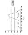
次に図4及び5を参照すると、図1の読み取りヘッド10が、LightTools(登録商標)ソフトウェアモデルを使用してコンピュータ上でシミュレートされている。プロットは、導光体16なしの場合(図4)及び導光体を使用する場合(図5)で、検出器34の表面の照射強さをそのX軸及びY軸に沿って示す。SMD LED12中のLEDダイは、SMD LED12のパッケージのY軸から約0.43mmのオフセットを有するようにモデル化されている(SMD LED中の3個のLEDダイの理由として、それぞれはSMD LEDパッケージ内で中心から約0.43mm偏っている)。図4は、導光体16が除かれる場合、検出器34のY軸沿いの照射分布がどちらかといえば不均一であり、「ホットスポット」(すなわち、比較的大きい強さの区域)を含むということを示す。検出器のX軸に沿っては、強さ分布はいくらかより均一である。しかし、導光体16なしでは強さが低い。
Referring now to FIGS. 4 and 5, the
図5から見てとれるように、導光体16の追加は、検出器34の表面における少なくとも一部には導光体16中の連続的な側壁反射によって、照射分布及び強さを大きく改善する。本発明者は、約2.3mm平方である断面を有する少なくとも5cmの導光体が、側壁内反射の数を、導光体16の出力端18で均一な照射を生じさせるのに十分なほど増大させるということを見いだした。
As can be seen from FIG. 5, the addition of the
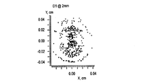
本発明者はまた、正方形の断面を有する導光体が丸い断面を有する導光体よりも良好な結果を生じさせるということを見いだした。次に図6及び7を参照すると、読み取りヘッド10(図1)に関して強さ分布プロットが示されている。しかし、図6に関して使用される読み取りヘッド10は、丸い断面(直径約2.3mm)を有する導光体16を具現化するが、図7に関して使用される読み取りヘッド10は、正方形の断面(約2.3mm×約2.3mm)を有する導光体16を使用したものである。図6及び7は、サンプル光束開口24から2mm、5mm及び10mmのところに配置された3個の異なる検出器に対応するそれぞれ三つの強さ分布プロットを含む。丸い導光体(図6)は、3個の検出器それぞれで不均一な強さ分布を生じさせ、分布は検出器ごとに異なる。正方形の導光体(図7)は、3個の検出器それぞれで実質的に均一な分布を生じさせる。放射照度は、丸い導光体の場合で約4.9μW/cm2であり、正方形の導光体の場合で約6.8μW/cm2である。したがって、正方形の導光体16は、より多量の光がサンプルに伝送され、サンプル開口と検出器との距離に依存せずにより均一な照射分布が得られる結果をもたらす。
The inventor has also found that a light guide with a square cross-section produces better results than a light guide with a round cross-section. Referring now to FIGS. 6 and 7, an intensity distribution plot is shown for the read head 10 (FIG. 1). However, while the read
図8を参照すると、本発明の代替態様による多重波長拡散反射型読み取りヘッド(「反射型読み取りヘッド」)100が示されている。図1〜3に示す多重波長透過型読み取りヘッド10と同じく、反射型読み取りヘッド100は、複数の波長を導光体16に入力するための、PCB14に配置されたSMD LED12を含む。光は、導光体16の中を全内反射によって誘導されて、コリメート開口20と、実質的に平行にされた光束26をサンプルフォーマット102に出力するコリメートレンズ22とを含むコリメート光学系に達する。光26は、サンプルフォーマット102の読み取り区域108に配置されたサンプルを照射する。サンプルフォーマット102又は少なくともフォーマットの読み取り区域108は、拡散反射膜、たとえば紙又はポリスチレンビーズのフィルムで構成されている。本発明の一つの実施態様によると、反射型読み取りヘッド100の導光体16は、図1に示す透過型読み取りヘッド10に関連して記載したものに類似した正方形の断面を有している。
Referring to FIG. 8, a multi-wavelength diffuse reflective read head (“reflective read head”) 100 according to an alternative aspect of the present invention is shown. Similar to the multiple wavelength transmission read
光26はサンプルから散乱する。この散乱光を参照番号110で示す。散乱光110は、サンプルの表面から反射する光、サンプルの中から反射する光及びフォーマット102のサンプル読み取り区域108から反射する光を含む。散乱光110の一部は光ファイバケーブル114によって収集され、この光ファイバが、収集した散乱光を検出器34に戻す。本発明の一つの実施態様によると、光ファイバケーブル114は約0.51の開口数を有し、これは、約1mmのサンプルを視野に入れる約30゜の受光円錐に限定される視野域に換算される。光ファイバケーブル114の受光円錐内に入る散乱光110は、検出器34に戻される。
拡散反射率精度の問題は、光学部品の機械的アライメント変動によって生じる。さらに、サンプル光束直径、発散、強さ分布及び位置がすべて誤差に寄与する。これらのタイプの誤差及び問題は、反射率に基づくシステムの精度に直接影響する要因である。反射型読み取りヘッド100のいくつかの部品がこれらのタイプの誤差を減らすのに貢献する。正方形の断面を有する導光体16は光束形状寸法の変化を減らす。SMD LED12は不均一な強さ分布を出力し、この出力が導光体16によって均一に補正される結果、SMD LED12内のLEDダイの位置にかかわらず、波長ごとにサンプルで実質的に同一の光束直径、発散及びアライメントが得られる。導光体16は、実質的な均一な輻射照度分布をもたらす導光体16内の連続的な側壁反射を考慮している。
The problem of diffuse reflectance accuracy is caused by mechanical alignment variations of optical components. Furthermore, the sample beam diameter, divergence, intensity distribution and position all contribute to the error. These types of errors and problems are factors that directly affect the accuracy of systems based on reflectivity. Several components of the
拡散反射率用途はまた、サンプル高さ感度によって生じる精度問題を被りやすい。サンプル高さ感度とは、サンプルフォーマット102の読み取り場所又は高さによって生じる反射率変動の量をいう。たとえば、サンプル場所は種々のサンプル及び計器の間で異なり、各場所が、公称サンプル場所に対して反射率変化を生じさせる結果、精度誤差が出る。読み取り区域108のサンプルを平行にされた光26で照射することにより、減少したサンプル高さ感度性能が達成される。平行にされた光は、サンプルが公称読み取り高さに近づき、それから離れるとき、照射読み取り区域108中でより小さな変化を生じさせる。同様に、サンプル傾き感度もまた、サンプルを平行にされた光26によって照射することによって低下する。サンプル傾きとは、読み取り区域108中のサンプルの向きをいう。たとえば、反応区域108中のサンプルは、光束26に対して垂直に保持されないかもしれず、傾きの変化が性能問題を生じさせることがある。さらには、上記で論じたように、導光体16とSMD LED12との密な連結は、SMD LED12によって出力される光の大部分(約92%)が導光体16によって収集されるように考慮している。
Diffuse reflectance applications are also subject to accuracy problems caused by sample height sensitivity. Sample height sensitivity refers to the amount of reflectance variation caused by the reading location or height of the
本発明は、種々の変形及び代替形態を受けることができるが、その具体的な実施態様を図面で一例として示し、本明細書で詳細に説明した。しかし、本発明を、開示される特定の形態に限定することを意図せず、それどころか、特許請求の範囲によって定義される発明の本質及び範囲に当てはまるすべての変形、均等及び代替を包含する意図であるということが理解されるべきである。 While the invention is susceptible to various modifications and alternative forms, specific embodiments thereof are shown by way of example in the drawings and have been described in detail herein. However, it is not intended to limit the invention to the particular form disclosed, but rather to encompass all modifications, equivalents and alternatives that fall within the essence and scope of the invention as defined by the claims. It should be understood that there is.
Claims (10)
サンプルを受けるための読み取り区域と、
複数の波長の光を出力するための複数の発光素子と、
入力端及び出力端を有し、前記入力端が、前記複数の発光素子によって出力される光を受けるために前記複数の発光素子に直接結合されており、前記入力端が、前記複数の発光素子の少なくとも1つの中心から偏っている中心を有するものである、前記出力端に受けられた光の実質的部分を誘導し、かつ、実質的に均一な空間的分布を形成する正方形の導光体と、
前記導光体の前記出力端から光を受け、かつ、実質的に平行にされた光束で前記サンプルを照射するためのレンズと、
前記サンプルの照射に応答して前記サンプルからの透過光を検出するための検出器と
を含む読み取りヘッド。 A read head for use in measuring the concentration of an analyte in a sample,
A reading area for receiving samples;
A plurality of light emitting elements for outputting light of a plurality of wavelengths;
An input end and an output end, wherein the input end is directly coupled to the plurality of light emitting elements to receive light output by the plurality of light emitting elements, and the input end includes the plurality of light emitting elements. A square light guide that has a center that is offset from at least one center of the light and that induces a substantial portion of the light received at the output end and forms a substantially uniform spatial distribution When,
A lens for receiving light from the output end of the light guide and irradiating the sample with a substantially parallel light beam;
A read head including a detector for detecting transmitted light from the sample in response to illumination of the sample.
生物学サンプルを受けるための、前記生物学的サンプルと反応して血液サンプル中の分析対象物の濃度を示す比色反応を生じさせるための試薬を有する反応区域を含む試験ストリップと、
試験ストリップの少なくとも前記反応区域を受けるための試験ストリップ受け入れ区域と、
前記比色反応における変色の程度を計測する際に使用される読み取りヘッドであって、
複数の波長の光を出力するための複数の発光素子を含む光源、
入力端及び出力端を有し、前記入力端が、前記複数の発光素子によって出力される光を受けるために前記光源に直接結合されており、前記入力端が、前記複数の発光素子の少なくとも1つの中心から偏っている中心を有するものである、前記出力端に受けられた光の実質的部分を誘導し、かつ、実質的に均一な空間的分布を形成する正方形の導光体、
前記導光体の前記出力端から光を受け、実質的に平行にされた光束で前記試験ストリップの前記反応区域を照射するためのコリメートレンズ、ならびに
前記試薬と反応した前記分析対象物を含む前記生物学的サンプルを含有する前記試験ストリップ中の前記反応区域からの光を検出するための検出器
を含む読み取りヘッドと
を含む装置。 An apparatus for measuring the concentration of an analyte in a biological sample,
A test strip comprising a reaction zone for receiving a biological sample having a reagent for reacting with said biological sample to produce a colorimetric reaction indicative of the concentration of the analyte in the blood sample;
A test strip receiving area for receiving at least said reaction zone of the test strip;
A read head used in measuring the degree of color change in the colorimetric reaction,
A light source including a plurality of light emitting elements for outputting light of a plurality of wavelengths;
An input end and an output end, wherein the input end is directly coupled to the light source for receiving light output by the plurality of light emitting elements, and the input end is at least one of the plurality of light emitting elements. A square light guide that induces a substantial portion of the light received at the output end and that forms a substantially uniform spatial distribution, having a center that is offset from one center;
A collimating lens for receiving light from the output end of the light guide and irradiating the reaction zone of the test strip with a substantially collimated light beam; and the analyte reacted with the reagent A read head including a detector for detecting light from the reaction zone in the test strip containing a biological sample.
前記読み取りヘッドの読み取り区域で分析対象物を含む生物学的サンプルを試薬と反応させる工程と、
前記読み取り区域を複数の波長の複数の光束で照射する工程と、
複数の発光素子に直接結合されている正方形の導光体によって、前記複数の光束を実質的に均一な空間的分布で前記読み取り区域に伝送する工程と、
前記サンプルを照射する前に前記光束を実質的に平行にする工程と、
前記サンプル内の前記分析対象物の濃度を測定することを支援するために、前記サンプルを介して透過光の光学的反応を検出する工程と
を含む方法。 A method for measuring the concentration of an analyte in a biological sample using a multi-wavelength read head for measuring a colorimetric reaction between the reagent and the analyte in the biological sample, comprising:
Reacting a biological sample containing an analyte with a reagent in a read area of the read head;
Irradiating the reading area with a plurality of light beams of a plurality of wavelengths;
Transmitting the plurality of light beams to the reading area in a substantially uniform spatial distribution by a square light guide directly coupled to the plurality of light emitting elements;
Making the luminous flux substantially parallel before illuminating the sample;
Detecting an optical response of transmitted light through the sample to assist in measuring the concentration of the analyte in the sample.
Applications Claiming Priority (2)
| Application Number | Priority Date | Filing Date | Title |
|---|---|---|---|
| US44627903P | 2003-02-11 | 2003-02-11 | |
| US60/446,279 | 2003-02-11 |
Publications (3)
| Publication Number | Publication Date |
|---|---|
| JP2004317487A JP2004317487A (en) | 2004-11-11 |
| JP2004317487A5 JP2004317487A5 (en) | 2007-03-29 |
| JP4804716B2 true JP4804716B2 (en) | 2011-11-02 |
Family
ID=32682465
Family Applications (1)
| Application Number | Title | Priority Date | Filing Date |
|---|---|---|---|
| JP2004033124A Expired - Fee Related JP4804716B2 (en) | 2003-02-11 | 2004-02-10 | Multi-wavelength read head for use in measuring analytes in body fluids |
Country Status (8)
| Country | Link |
|---|---|
| US (1) | US7154592B2 (en) |
| EP (1) | EP1447658B1 (en) |
| JP (1) | JP4804716B2 (en) |
| CN (1) | CN1521495A (en) |
| AU (1) | AU2004200505A1 (en) |
| CA (1) | CA2457170C (en) |
| DK (1) | DK1447658T3 (en) |
| ES (1) | ES2558862T3 (en) |
Families Citing this family (44)
| Publication number | Priority date | Publication date | Assignee | Title |
|---|---|---|---|---|
| RU2400733C2 (en) * | 2004-12-13 | 2010-09-27 | Байер Хелткэр Ллк | Transmission spectroscopy system for use in determining analysed substances in body fluids |
| ATE530906T1 (en) * | 2004-12-13 | 2011-11-15 | Bayer Healthcare Llc | METHOD FOR DISTINCTION BETWEEN BLOOD AND CONTROL SOLUTIONS CONTAINING A COMMON ANALYTE |
| US20060281187A1 (en) | 2005-06-13 | 2006-12-14 | Rosedale Medical, Inc. | Analyte detection devices and methods with hematocrit/volume correction and feedback control |
| US8382681B2 (en) | 2005-09-30 | 2013-02-26 | Intuity Medical, Inc. | Fully integrated wearable or handheld monitor |
| US8789756B2 (en) * | 2006-02-25 | 2014-07-29 | Roche Diagnostics Operations, Inc. | Test element coding apparatuses, systems and methods |
| US20110009720A1 (en) * | 2006-11-02 | 2011-01-13 | Kislaya Kunjan | Continuous whole blood glucose monitor |
| EP1987762A1 (en) | 2007-05-03 | 2008-11-05 | F.Hoffmann-La Roche Ag | Oximeter |
| JP2008281394A (en) * | 2007-05-09 | 2008-11-20 | Olympus Corp | Automatic analysis apparatus |
| US7576333B2 (en) * | 2007-08-01 | 2009-08-18 | Corning Incorporated | Optical interrogation system and method for using same |
| US20090155921A1 (en) * | 2007-12-12 | 2009-06-18 | Arbor Vita Corporation | Method and apparatus for reading test strips |
| CA2725264C (en) | 2008-05-30 | 2017-06-20 | Intuity Medical, Inc. | Body fluid sampling device -- sampling site interface |
| US9636051B2 (en) | 2008-06-06 | 2017-05-02 | Intuity Medical, Inc. | Detection meter and mode of operation |
| US20110098590A1 (en) * | 2009-10-26 | 2011-04-28 | Pulse Health Llc | Methods and apparatuses for detecting analytes |
| EP2325624A1 (en) * | 2009-11-18 | 2011-05-25 | F. Hoffmann-La Roche AG | Method and device for inspecting a bodily fluid |
| WO2011065981A1 (en) | 2009-11-30 | 2011-06-03 | Intuity Medical, Inc. | Calibration material delivery devices and methods |
| CN102243375B (en) * | 2010-04-29 | 2014-02-12 | 韩国电子通信研究院 | Light distributor and portable device employing light distributor for urine analysis |
| JP6223337B2 (en) | 2011-08-03 | 2017-11-08 | インテュイティ メディカル インコーポレイテッド | Body fluid extraction measuring instrument |
| US8894262B2 (en) * | 2013-03-11 | 2014-11-25 | Roche Diagnostic Operations, Inc. | Blood glucose test strip illumination device and method |
| CN105090810A (en) * | 2014-05-16 | 2015-11-25 | 科宝智慧医疗科技(上海)有限公司 | Illumination device |
| US10267679B2 (en) | 2014-07-23 | 2019-04-23 | Ascensia Diabetes Care Holdings Ag | Light switching indicators by wavelength filtration for a testing device |
| WO2016027202A2 (en) * | 2014-08-19 | 2016-02-25 | Biolab Technologies Ltd. | Device, system and method for non-invasively measuring blood glucose |
| US9606068B2 (en) * | 2014-08-27 | 2017-03-28 | Pacific Biosciences Of California, Inc. | Arrays of integrated analytical devices |
| GB201415435D0 (en) * | 2014-09-01 | 2014-10-15 | Pilkington Group Ltd | Furnace atmosphere measurement |
| CN104248421B (en) * | 2014-09-24 | 2016-06-01 | 中国科学院电子学研究所 | A kind of reflective photoelectric sensor for gingival blood flow monitoring and its preparation method |
| US10932727B2 (en) | 2015-09-25 | 2021-03-02 | Sanmina Corporation | System and method for health monitoring including a user device and biosensor |
| US9788767B1 (en) | 2015-09-25 | 2017-10-17 | Sanmina Corporation | System and method for monitoring nitric oxide levels using a non-invasive, multi-band biosensor |
| US10194871B2 (en) | 2015-09-25 | 2019-02-05 | Sanmina Corporation | Vehicular health monitoring system and method |
| US10952682B2 (en) | 2015-07-19 | 2021-03-23 | Sanmina Corporation | System and method of a biosensor for detection of health parameters |
| US10321860B2 (en) * | 2015-07-19 | 2019-06-18 | Sanmina Corporation | System and method for glucose monitoring |
| US9636457B2 (en) | 2015-07-19 | 2017-05-02 | Sanmina Corporation | System and method for a drug delivery and biosensor patch |
| US10750981B2 (en) | 2015-09-25 | 2020-08-25 | Sanmina Corporation | System and method for health monitoring including a remote device |
| US10736580B2 (en) | 2016-09-24 | 2020-08-11 | Sanmina Corporation | System and method of a biosensor for detection of microvascular responses |
| US10973470B2 (en) | 2015-07-19 | 2021-04-13 | Sanmina Corporation | System and method for screening and prediction of severity of infection |
| US10744261B2 (en) | 2015-09-25 | 2020-08-18 | Sanmina Corporation | System and method of a biosensor for detection of vasodilation |
| US10888280B2 (en) | 2016-09-24 | 2021-01-12 | Sanmina Corporation | System and method for obtaining health data using a neural network |
| CN104964974B (en) * | 2015-07-27 | 2017-10-20 | 张银虎 | Intelligent instrument for detecting pesticide residue through |
| US10945676B2 (en) | 2015-09-25 | 2021-03-16 | Sanmina Corporation | System and method for blood typing using PPG technology |
| JP6549315B2 (en) * | 2015-10-05 | 2019-07-24 | ディア−ビット リミテッドDia−Vit Ltd. | Device for non-invasive measurement of blood glucose levels |
| ITUB20156826A1 (en) * | 2015-12-09 | 2017-06-09 | Dnaphone S R L | OPTO-ELECTRONIC DEVICE FOR THE USE IN THE COLORIMETRIC ANALYSIS OF A FLUID, APPARATUS AND COLORIMETRIC ANALYSIS SAMPLE OF A FLUID SAMPLE |
| CN105973847B (en) * | 2016-06-24 | 2019-03-01 | 广州新晖汽车零部件有限公司 | A kind of auto lamp leaded light bar detection device |
| US10466783B2 (en) | 2018-03-15 | 2019-11-05 | Sanmina Corporation | System and method for motion detection using a PPG sensor |
| CN112997067A (en) | 2018-12-28 | 2021-06-18 | 泰尔茂株式会社 | Test strip and component measurement system |
| KR102248263B1 (en) * | 2019-03-27 | 2021-05-06 | 경북대학교 산학협력단 | A method of detecting a sample change using a light source control method, the light source control method, and a sample change detection device |
| CN110296943A (en) * | 2019-06-11 | 2019-10-01 | 苏州健康在线医疗科技股份有限公司 | A kind of dry type test paper Light-Echo detection device and its detection method |
Family Cites Families (22)
| Publication number | Priority date | Publication date | Assignee | Title |
|---|---|---|---|---|
| US5028139A (en) | 1987-07-16 | 1991-07-02 | Miles Inc. | Readhead for reflectance measurement of distant samples |
| JP2590129B2 (en) * | 1987-08-19 | 1997-03-12 | 株式会社リコー | Liquid physical property measurement device |
| US5305093A (en) | 1991-10-31 | 1994-04-19 | Miles Inc. | Spectrometer for conducting turbidimetric and colormetric measurements |
| AU3583293A (en) * | 1992-01-17 | 1993-08-03 | Government Of The United States Of America, As Represented By The Secretary Of The Department Of Health And Human Services, The | Optical method for monitoring arterial blood hematocrit |
| US5303037A (en) * | 1992-02-24 | 1994-04-12 | Eaton Corporation | Color sensor illumination source employing a lightpipe and multiple LEDs |
| US5349504A (en) * | 1993-07-12 | 1994-09-20 | Dialight Corporation | Multi-level lightpipe design for SMD LEDs |
| US5747806A (en) * | 1996-02-02 | 1998-05-05 | Instrumentation Metrics, Inc | Method and apparatus for multi-spectral analysis in noninvasive nir spectroscopy |
| US6630947B1 (en) * | 1996-04-10 | 2003-10-07 | The United States Of America As Represented By The Secretary Of The Navy | Method for examining subsurface environments |
| CA2250400A1 (en) | 1996-04-30 | 1997-11-06 | Metrika, Inc. | Method and device for measuring reflected optical radiation |
| GB9704737D0 (en) * | 1997-03-07 | 1997-04-23 | Optel Instr Limited | Biological measurement system |
| US5877863A (en) | 1997-03-20 | 1999-03-02 | Bayer Corporation | Readhead for a photometric diagnostic instrument |
| JP2001516894A (en) * | 1997-09-18 | 2001-10-02 | テレダイン・ライティング・アンド・ディスプレイ・プロダクツ・インコーポレーテッド | Highly efficient direct coupling of radiated electromagnetic energy into a dielectric waveguide structure |
| JP4426026B2 (en) * | 1998-08-07 | 2010-03-03 | シスメックス株式会社 | Multi-light source unit and optical system using the same |
| EP1208367A4 (en) * | 1999-08-06 | 2007-03-07 | Cambridge Res & Instrmnt Inc | Spectral imaging system |
| US6741875B1 (en) * | 1999-08-31 | 2004-05-25 | Cme Telemetrix Inc. | Method for determination of analytes using near infrared, adjacent visible spectrum and an array of longer near infrared wavelengths |
| JP4188537B2 (en) * | 2000-04-12 | 2008-11-26 | 浜松ホトニクス株式会社 | Immunochromatographic test piece measuring device |
| JP4188538B2 (en) * | 2000-04-12 | 2008-11-26 | 浜松ホトニクス株式会社 | Immunochromatographic test piece measuring device |
| GB2362526B (en) * | 2000-05-18 | 2004-04-14 | Mitel Corp | Combined visible and infrared pipe |
| JP3944356B2 (en) * | 2001-01-17 | 2007-07-11 | 株式会社リコー | Liquid concentration detection device and wet image forming apparatus provided with the liquid concentration detection device |
| JP3518518B2 (en) * | 2001-03-05 | 2004-04-12 | 松下電器産業株式会社 | Banknote recognition device |
| US20040147034A1 (en) * | 2001-08-14 | 2004-07-29 | Gore Jay Prabhakar | Method and apparatus for measuring a substance in a biological sample |
| US6954260B2 (en) * | 2002-01-17 | 2005-10-11 | Cross Match Technologies, Inc. | Systems and methods for illuminating a platen in a print scanner |
-
2004
- 2004-02-02 US US10/770,059 patent/US7154592B2/en not_active Expired - Fee Related
- 2004-02-09 CA CA2457170A patent/CA2457170C/en not_active Expired - Fee Related
- 2004-02-10 JP JP2004033124A patent/JP4804716B2/en not_active Expired - Fee Related
- 2004-02-10 EP EP04002865.6A patent/EP1447658B1/en not_active Expired - Lifetime
- 2004-02-10 DK DK04002865.6T patent/DK1447658T3/en active
- 2004-02-10 CN CNA2004100396217A patent/CN1521495A/en active Pending
- 2004-02-10 ES ES04002865.6T patent/ES2558862T3/en not_active Expired - Lifetime
- 2004-02-10 AU AU2004200505A patent/AU2004200505A1/en not_active Abandoned
Also Published As
| Publication number | Publication date |
|---|---|
| AU2004200505A1 (en) | 2004-08-26 |
| CN1521495A (en) | 2004-08-18 |
| EP1447658B1 (en) | 2015-10-21 |
| CA2457170A1 (en) | 2004-08-11 |
| EP1447658A1 (en) | 2004-08-18 |
| DK1447658T3 (en) | 2016-01-25 |
| CA2457170C (en) | 2015-11-24 |
| US7154592B2 (en) | 2006-12-26 |
| US20040157341A1 (en) | 2004-08-12 |
| ES2558862T3 (en) | 2016-02-09 |
| JP2004317487A (en) | 2004-11-11 |
Similar Documents
| Publication | Publication Date | Title |
|---|---|---|
| JP4804716B2 (en) | Multi-wavelength read head for use in measuring analytes in body fluids | |
| AU725643B2 (en) | Method and device for measuring reflected optical radiation | |
| JP2914755B2 (en) | Test strip reader | |
| US5701181A (en) | Fiber optic diffuse light reflectance sensor utilized in the detection of occult blood | |
| KR100219252B1 (en) | Analytical system with means for detecting too small sample volumes | |
| KR100816799B1 (en) | Test element analysis system and method for analytical investigation using the same | |
| JP2005338101A (en) | Method for photometric analysis of test element | |
| JPH10267833A (en) | Reading head of photometric diagnosing apparatus | |
| JP4704402B2 (en) | Method and system for analyzing samples on test elements | |
| JP2015514960A (en) | Sample monitor | |
| WO2006019543A2 (en) | Read-head for optical diagnostic device | |
| AU2004200217A1 (en) | Molded Low Volume Waveguided Optical Format | |
| US20230003722A1 (en) | Methods and compositions for lateral flow analyte assays | |
| JPS5995441A (en) | Measuring device for reflected light | |
| JP2007127448A (en) | Analyzing optical device |
Legal Events
| Date | Code | Title | Description |
|---|---|---|---|
| A521 | Request for written amendment filed |
Free format text: JAPANESE INTERMEDIATE CODE: A523 Effective date: 20070207 |
|
| A621 | Written request for application examination |
Free format text: JAPANESE INTERMEDIATE CODE: A621 Effective date: 20070207 |
|
| A131 | Notification of reasons for refusal |
Free format text: JAPANESE INTERMEDIATE CODE: A131 Effective date: 20091110 |
|
| A601 | Written request for extension of time |
Free format text: JAPANESE INTERMEDIATE CODE: A601 Effective date: 20100128 |
|
| A602 | Written permission of extension of time |
Free format text: JAPANESE INTERMEDIATE CODE: A602 Effective date: 20100202 |
|
| A521 | Request for written amendment filed |
Free format text: JAPANESE INTERMEDIATE CODE: A523 Effective date: 20100310 |
|
| A131 | Notification of reasons for refusal |
Free format text: JAPANESE INTERMEDIATE CODE: A131 Effective date: 20100907 |
|
| A601 | Written request for extension of time |
Free format text: JAPANESE INTERMEDIATE CODE: A601 Effective date: 20101118 |
|
| A602 | Written permission of extension of time |
Free format text: JAPANESE INTERMEDIATE CODE: A602 Effective date: 20101124 |
|
| A521 | Request for written amendment filed |
Free format text: JAPANESE INTERMEDIATE CODE: A523 Effective date: 20110204 |
|
| TRDD | Decision of grant or rejection written | ||
| A01 | Written decision to grant a patent or to grant a registration (utility model) |
Free format text: JAPANESE INTERMEDIATE CODE: A01 Effective date: 20110726 |
|
| A01 | Written decision to grant a patent or to grant a registration (utility model) |
Free format text: JAPANESE INTERMEDIATE CODE: A01 |
|
| A61 | First payment of annual fees (during grant procedure) |
Free format text: JAPANESE INTERMEDIATE CODE: A61 Effective date: 20110810 |
|
| R150 | Certificate of patent or registration of utility model |
Ref document number: 4804716 Country of ref document: JP Free format text: JAPANESE INTERMEDIATE CODE: R150 Free format text: JAPANESE INTERMEDIATE CODE: R150 |
|
| FPAY | Renewal fee payment (event date is renewal date of database) |
Free format text: PAYMENT UNTIL: 20140819 Year of fee payment: 3 |
|
| R250 | Receipt of annual fees |
Free format text: JAPANESE INTERMEDIATE CODE: R250 |
|
| R250 | Receipt of annual fees |
Free format text: JAPANESE INTERMEDIATE CODE: R250 |
|
| R250 | Receipt of annual fees |
Free format text: JAPANESE INTERMEDIATE CODE: R250 |
|
| R250 | Receipt of annual fees |
Free format text: JAPANESE INTERMEDIATE CODE: R250 |
|
| R250 | Receipt of annual fees |
Free format text: JAPANESE INTERMEDIATE CODE: R250 |
|
| R250 | Receipt of annual fees |
Free format text: JAPANESE INTERMEDIATE CODE: R250 |
|
| R250 | Receipt of annual fees |
Free format text: JAPANESE INTERMEDIATE CODE: R250 |
|
| R250 | Receipt of annual fees |
Free format text: JAPANESE INTERMEDIATE CODE: R250 |
|
| LAPS | Cancellation because of no payment of annual fees |