JP4804366B2 - Construction machine seal structure - Google Patents
Construction machine seal structure Download PDFInfo
- Publication number
- JP4804366B2 JP4804366B2 JP2007001658A JP2007001658A JP4804366B2 JP 4804366 B2 JP4804366 B2 JP 4804366B2 JP 2007001658 A JP2007001658 A JP 2007001658A JP 2007001658 A JP2007001658 A JP 2007001658A JP 4804366 B2 JP4804366 B2 JP 4804366B2
- Authority
- JP
- Japan
- Prior art keywords
- grommet
- insertion hole
- hole
- construction machine
- string
- Prior art date
- Legal status (The legal status is an assumption and is not a legal conclusion. Google has not performed a legal analysis and makes no representation as to the accuracy of the status listed.)
- Active
Links
Images


Landscapes
- Component Parts Of Construction Machinery (AREA)
- Insulating Bodies (AREA)
- Installation Of Indoor Wiring (AREA)
Description
本発明は建設機械のシール構造に関するものであり、特に、建設機械の運転室と室外とを仕切る隔壁の貫通孔に弾性体のグロメットを装着し、該グロメットの挿通孔に紐状体または棒状体を挿通させてなる建設機械のシール構造に関するものである。 TECHNICAL FIELD The present invention relates to a construction machine sealing structure, and in particular, an elastic grommet is attached to a through hole of a partition wall that divides an operator's cab from the outdoor of a construction machine, and a string-like body or a rod-like body is inserted into the insertion hole of the grommet. The present invention relates to a construction machine seal structure.
一般に、油圧ショベルのような建設機械においては、運転室内の操作レバーから延びる油圧ホース等の棒状体や電気ハーネス等の紐状体が、床面および隔壁を貫通して室外に配管もしくは配線されている。この場合、床面あるいは隔壁等には貫通孔が穿設され、該貫通孔に弾性材のグロメットが嵌められ、該グロメットで前記棒状体や紐状体等を保持するようにしたものが知られている(例えば、特許文献1参照)。 In general, in a construction machine such as a hydraulic excavator, a rod-like body such as a hydraulic hose extending from an operation lever in a cab or a string-like body such as an electric harness penetrates a floor surface and a partition wall and is piped or wired outside the room. Yes. In this case, a through-hole is formed in the floor surface or the partition wall, and a grommet made of an elastic material is fitted in the through-hole so that the rod-like body, string-like body, etc. are held by the grommet. (For example, refer to Patent Document 1).
上記グロメットは、紐状体または棒状体を挿通させる挿通孔を設けた1つの平板状の部材で形成されている。また、グロメットは、防塵および防音効果を持たせるために、挿入孔に挿入された紐状体または棒状体を、グロメットとの間に隙間を設けずに密着した状態で保持している。
しかしながら、特許文献1記載の発明におけるシール構造等で使用されているグロメットは、紐状体または棒状体を挿通孔に取り付ける場合、グロメットの外周面から設けられている切り込み部分を弾性変形させて一時的に拡開し、この切り込み部分を通して、グロメットの側方から紐状体または棒状体を挿通孔に差し込むようにしているので、取り付けが面倒であった。特に、取り付け本数が多いときには、この差し込み作業を一本ずつ、順に行うことになるので、さらに作業性が悪いという問題があった。 However, in the grommet used in the seal structure or the like in the invention described in Patent Document 1, when a string-like body or a rod-like body is attached to the insertion hole, the notch portion provided from the outer peripheral surface of the grommet is elastically deformed to temporarily Since the string-like body or the rod-like body is inserted into the insertion hole from the side of the grommet through the cut portion, the attachment is troublesome. In particular, when the number of attachments is large, the insertion work is performed one by one in order, and there is a problem that workability is further deteriorated.
そこで、紐状体または棒状体をシール用グロメットに取り付ける際に、取り付け作業性等を向上させるために解決すべき技術的課題が生じてくるのであり、本発明はこの課題を解決することを目的とする。 Therefore, when attaching the string-like body or the rod-like body to the sealing grommet, a technical problem to be solved in order to improve the mounting workability and the like arises, and the present invention aims to solve this problem. And
本発明は上記目的を達成するために提案されたものであり、請求項1記載の発明は、挿通孔を有し、該挿通孔に紐状体または棒状体を挿通させた弾性体からなるグロメットを、建設機械の隔壁の貫通孔に装着してなるシール構造において、
前記グロメットを、前記挿通孔を横切るような分割ラインで2分割した分割構造とし、上記挿通孔を、ほぼ真円形状で、かつ、その中心を上記分割ラインからずらして設け、上記2分割されたグロメットの一方の半体側に前記挿通孔を形成している半円以上の平面視C字形状の切欠部を設けた建設機械のシール構造を提供する。
The present invention has been proposed in order to achieve the above object, and the invention according to claim 1 is a grommet comprising an insertion hole, and an elastic body having a string-like body or a rod-like body inserted through the insertion hole. In the seal structure that is installed in the through hole of the partition wall of the construction machine,
The grommet has a split structure that is divided into two by a dividing line that crosses the insertion hole, the insertion hole has a substantially circular shape, and the center thereof is shifted from the dividing line, and is divided into two. Provided is a construction machine seal structure in which a cutout portion having a C-shape in plan view of a semicircle or more forming the insertion hole is provided on one half body side of a grommet.
この構成によれば、2つに分割されているグロメット半体同士を、紐状体または棒状体を間に挟んで突き合わせると、紐状体または棒状体が挿通孔に挿通された1つのグロメットが容易に組み立てられる。また、この状態でグロメットを隔壁の貫通孔に取り付けると、このグロメットを介して紐状体または棒状体を隔壁に保持することができる。 According to this configuration, when the grommets halves divided into two are abutted with the string-like body or rod-like body sandwiched therebetween, one grommet in which the string-like body or rod-like body is inserted through the insertion hole Is easily assembled. Moreover, if a grommet is attached to the through-hole of a partition in this state, a string-like body or a rod-shaped body can be hold | maintained to a partition via this grommet.
また、この構成によれば、一方のグロメット半体側に設けた半円以上の平面視C字形状の切欠部内に紐状体または棒状体を嵌め込み、一方のグロメット半体と紐状体または棒状体を仮固定した状態で、該一方のグロメット半体に他方のグロメット半体を突き合わせると、紐状体または棒状体が挿通孔に挿通された一つのグロメットとして組み立てることができる。また、この状態でグロメットを隔壁の貫通孔に取り付けると、このグロメットを介して紐状体または棒状体を隔壁に保持することができる。 Further , according to this configuration, the string-like body or the rod-like body is fitted into the cutout portion of the C-shape in plan view or more provided on the side of the one grommet half-body, and the one grommet half and the string-like body or the rod-like body When the other grommet half is abutted against the one grommet half in a temporarily fixed state, the string-like body or the rod-like body can be assembled as one grommet inserted through the insertion hole. Moreover, if a grommet is attached to the through-hole of a partition in this state, a string-like body or a rod-shaped body can be hold | maintained to a partition via this grommet.
請求項2記載の発明は、請求項1において、上記挿通孔の内周縁に、内側に向かって延出された薄肉状の縁取り部をほぼ全周に亘って設けた建設機械のシール構造を提供する。 A second aspect of the present invention provides a construction machine seal structure according to the first aspect, wherein a thin edge portion extending inwardly is provided on the inner peripheral edge of the insertion hole over substantially the entire circumference. To do.
この構成によれば、挿通孔に挿通された紐状体または棒状体の周面に薄肉状の縁取り部を弾発的に押し付けて抱持し、該紐状体または棒状体と挿通孔との間の隙間や、該隙間によるズレを吸収して、隙間を実効的に無くすことができる。 According to this structure, the thin-walled rim portion is elastically pressed and held on the circumferential surface of the string-like body or rod-like body inserted through the insertion hole, and the string-like body or rod-like body and the insertion hole are The gap can be effectively eliminated by absorbing the gap between the gaps and the gap caused by the gap.
請求項3記載の発明は、請求項1,2において、上記グロメットに、上記挿通孔内と切り込みを介して通じているとともに、上記紐状体または棒状体が挿通されていないときには孔を閉じている薄肉膜状の蓋片部を有する目隠し孔を設けた建設機械のシール構造を提供する。
The invention according to
この構成によれば、挿通させる紐状体または棒状体の本数が増えた場合に、通常は蓋片部で閉じられている目隠し孔内に通じている切り込みを通して、該挿通孔側から、紐状体または棒状体を目隠し孔内に挿通させることができる。また、紐状体または棒状体が挿通されると、薄肉膜状の蓋片部をめくり上がらせて逃がし、該薄肉膜状の蓋片部を紐状体または棒状体の周面に弾発的に押し付けて、該紐状体または棒状体を抱持することができる。 According to this configuration, when the number of string-like bodies or rod-like bodies to be inserted is increased, the string-like body is formed from the insertion hole side through the notch that is normally passed through the blind hole closed by the lid piece. The body or the rod-shaped body can be inserted into the blind hole. Further, when the string-like body or rod-like body is inserted, the thin-film-like lid piece is turned up and released, and the thin-film-like lid piece is elastically applied to the circumferential surface of the string-like body or the rod-like body. The string-like body or the rod-like body can be held.
請求項4記載の発明は、請求項3において、上記挿入孔と上記目隠し孔との間に、上記蓋片部よりも肉厚で、かつ上記切り込みにより2つに分割されている1対のリブ部を設けた建設機械のシール構造を提供する。
Fourth aspect of the present invention, in
この構成によれば、薄肉膜状の蓋片部が紐状体または棒状体の周面に弾発的に押し付けられて該紐状体または棒状体を抱持するとき、リブ部は弾性変形されずに、蓋片部だけが弾性変形してめくれ上がり、紐状体または棒状体と挿通孔との間の隙間を実効的に無くすことができる。 According to this configuration, when the thin film-like lid piece is elastically pressed against the circumferential surface of the string-like body or rod-like body to hold the string-like body or rod-like body, the rib portion is elastically deformed. In addition, only the lid piece is elastically deformed and turned up, and the gap between the string-like body or rod-like body and the insertion hole can be effectively eliminated.
請求項5記載の発明は、請求項3または4において、上記蓋片部を、上記目隠し孔の中心から該目隠し孔の内周縁に向かって放射状に設けられている切り込みにより分割された複数の小片で形成した建設機械のシール構造を提供する。 According to a fifth aspect of the present invention, in the third or fourth aspect , the plurality of small pieces are obtained by dividing the lid piece portion by notches provided radially from the center of the blind hole toward the inner peripheral edge of the blind hole. A construction machine sealing structure formed by
この構成によれば、複数の小片で紐状体または棒状体の周面を弾発的に抱持し、紐状体または棒状体と挿通孔との間の隙間や該隙間によるズレを吸収して、隙間を実効的に無くすことができる。 According to this configuration, the circumferential surface of the string-like body or rod-like body is elastically held by a plurality of small pieces, and the gap between the string-like body or rod-like body and the insertion hole and the deviation due to the gap are absorbed. Thus, the gap can be effectively eliminated.
請求項6記載の発明は、請求項4において、上記リブ部と上記蓋片部との間に、上記挿通孔に通じる切り込みと連通し、かつ前記目隠し孔の内周に沿って半円以上形成された切り込みを設け、該内周切り込みにより前記蓋片部と前記リブ部とを分離してなる建設機械のシール構造を提供する。 A sixth aspect of the present invention is the method according to the fourth aspect, wherein the rib portion and the lid piece portion communicate with the notch leading to the insertion hole and are formed in a semicircle or more along the inner periphery of the blind hole. A sealing structure for a construction machine is provided in which the cut portion is provided and the lid piece portion and the rib portion are separated by the inner peripheral cut portion.
この構成によれば、薄肉膜状の蓋片部とリブ部との間を切り込みにより分離させることで、リブ部が蓋片部と一緒にめくれ上がるのを防ぐことができる。 According to this configuration, the rib portion can be prevented from turning up together with the lid piece portion by separating the thin film-like lid piece portion and the rib portion by cutting.
請求項1記載の発明は、紐状体または棒状体を間に挟んで、2つに分割されているグロメット半体同士を突き合わせると、挿通孔に紐状体または棒状体が挿通された1つのグロメットとして容易に組み立てることができる。さらに、この状態でグロメットを隔壁の貫通孔に取り付けると、紐状体または棒状体をグロメットと共に隔壁に容易に保持することができるので、取付作業性が向上する。 According to the first aspect of the present invention, when the grommet halves divided into two are abutted with each other with the string-like body or the rod-like body sandwiched therebetween, the string-like body or the rod-like body is inserted into the insertion hole. Can be easily assembled as two grommets. Further, when the grommet is attached to the through hole of the partition wall in this state, the string-like body or the rod-like body can be easily held on the partition wall together with the grommet, so that attachment workability is improved.
そして、この発明は、挿入孔の中心を分割ラインからずらすことで、一方の半体側に半円以上の平面視C字形状の切欠部が残り、該切欠部に紐状体または棒状体を嵌め込ませると、一方の半体と紐状体または棒状体との間を位置決めした状態で、該一方の半体に対して他方の半体を組み付けることができるので、上記の効果に加えて、さらに取付作業性が向上する。 And, this invention, by shifting the center of the insertion hole from the dividing line, the remaining cut-out portion of the semicircle or more planar view C-shape on one half side, the string-like body or the rod-like body to the cutout portion when the fitted, in a state where between the positioning of the one half and the string-like body or the rod-shaped body, it is possible to assemble the other half with respect to one half of the, in addition to the above effects, Furthermore, the mounting workability is improved.
請求項2記載の発明は、薄肉状の縁取り部により、紐状体または棒状体と挿通孔との間の隙間や該隙間によるズレを吸収して隙間を実効的に無くすことができるので、請求項1記載の発明の効果に加えて、防音及び防塵性が向上する。
The invention according to
請求項3記載の発明は、挿通させる紐状体または棒状体の本数が増えた場合に、目隠し孔を使用して紐状体または棒状体を追加配置することができるので、変更に対する自由度が利く。また、目隠し孔に紐状体または棒状体を取付けた状態では、薄肉膜状の蓋片部をめくれ上がらせて逃がし、挿入後は薄肉膜状の蓋片部を弾性圧接させた状態で抱持することができる。これにより、請求項1,2の発明の効果に加えて、拡張性と防音性及び防塵性が向上する。
In the invention according to
請求項4記載の発明は、薄肉膜状の蓋片部が紐状体または棒状体を弾発的に抱持するとき、蓋片部だけが弾性変形してめくれ上がり、紐状体または棒状体と挿通孔との間の隙間を実効的に無くすことができるので、請求項3記載の発明に加えて、さらに防音及び防塵性が向上する。
According to the invention of claim 4 , when the thin-film-like lid piece portion elastically embraces the string-like body or rod-like body, only the lid piece portion is elastically deformed and turned up, and the string-like body or rod-like body In addition to the invention of
請求項5記載の発明は、複数の小片により、紐状体または棒状体を目隠し孔との間の隙間や該隙間によるズレを吸収して、隙間を実効的に無くすことができるので、請求項3または4の発明の効果に加えて、さらに防音及び防塵性が向上する。 The invention according to claim 5 can absorb the gap between the string-like body or the rod-like body with the blindfold hole and the gap caused by the gap and effectively eliminate the gap by the plurality of small pieces. In addition to the effects of the invention of 3 or 4, the soundproofing and dustproofing properties are further improved.
請求項6記載の発明は、薄肉膜状の蓋片部が紐状体または棒状体を弾発的に抱持するとき、蓋片部だけが弾性変形してめくれ上がり、紐状体または棒状体と挿通孔との間の隙間を実効的に無くすことができるので、請求項4の発明の効果に加えて、さらに防音及び防塵性が向上する。 According to a sixth aspect of the invention, when the lid pieces of the thin film-shaped to embrace the string-like body or the rod-like body to elastically, only the cover piece portion is increased curling elastically deformed, the string-like body or the rod-shaped body In addition to the effect of the invention of claim 4 , the soundproofing and dustproofing properties are further improved.
紐状体または棒状体をシール用グロメットに取り付ける際における取り付け作業性等を向上させるという目的を達成するために、挿通孔を有し、該挿通孔に紐状体または棒状体を挿通させた弾性体からなるグロメットを、建設機械の運転室と室外とを仕切る隔壁の貫通孔に装着してなる建設機械の運転室シール構造において、前記グロメットを、分割ラインを前記挿通孔内に通して2分割したことにより実現した。 In order to achieve the purpose of improving the attachment workability when attaching the string-like body or rod-like body to the sealing grommet, the elastic body has an insertion hole, and the string-like body or rod-like body is inserted into the insertion hole. In a construction machine cab seal structure in which a grommet made of a body is mounted in a through hole of a partition wall that divides the cab and the exterior of the construction machine, the grommet is divided into two by passing a dividing line through the insertion hole It was realized by doing.
以下、本発明の建設機械のシール構造について、好適な実施例をあげて説明する。図1は、本発明を適用した建設機械である油圧ショベルにおける運転室内の構造を示す斜視図である。運転室1の内部に運転者用の着座シート2を設置し、該着座シート2の左右両側にコンソールボックス3,3を配設してある。
Hereinafter, the seal structure of the construction machine of the present invention will be described with reference to preferred embodiments. FIG. 1 is a perspective view showing the structure of a cab in a hydraulic excavator that is a construction machine to which the present invention is applied. A driver's
コンソールボックス3,3の上面前部には、操作用ノブ4が設けられている。この操作ノブ4は、図示していない油圧ショベルの上部旋回体や作業機のブーム,アーム,バケット等を作動させるための各種の油圧シリンダを操作する。
An operation knob 4 is provided in front of the upper surface of the
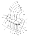
図2に示すように、操作用ノブ4はリモコンバルブ5の一端部に取り付けられており、該リモコンバルブ5の他端部には、運転室1と室外とを仕切る床面あるいは側壁等の隔壁7に設けた貫通孔8を貫通して、運転室1と室外とに延びる複数本(本実施例の場合では4本)のパイロットホース等の棒状体または電気ハーネス等の紐状体(以下、これら棒状体または紐状体を総称して、ホース6a,6b,6c,6dという)が連結されている。これらのホース6a〜6dは、シール用のグロメット9により結束され、該グロメット9を貫通孔8に嵌着することによって隔壁7に保持されている。
As shown in FIG. 2, the operation knob 4 is attached to one end portion of the remote control valve 5, and the other end portion of the remote control valve 5 is a partition wall such as a floor surface or a side wall that separates the cab 1 from the outside. 7 (four in the case of this embodiment) such as a pilot hose or a string-like body such as an electric harness (hereinafter, referred to as an electric harness) extending through the through-hole 8 provided in 7 These rod-like bodies or string-like bodies are collectively referred to as
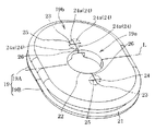
図3〜図6に前記グロメット9を詳細に示す。グロメット9は、例えばゴム若しくは軟質プラスチック等の弾性材にて平面視で略長円状に成形されている。該グロメット9は、中央の分割ラインLを境にして、グロメット半体9Aと9Bの2つに分割されており、この2つに分割されたグロメット半体9A,9Bの各対向面10,10を互いに突き合わせて、1つの上記略長円状のグロメット9に組み合わせて使用される。
3 to 6 show the
前記グロメット9は、中央部9aが比較的厚肉(例えば12ミリ)に形成されているとともに、この中央部9aに対して外周部9bがさらに厚肉(例えば21ミリ)に形成されている。また、グロメット9の外周部9bには、隔壁7の貫通孔8に嵌り合う溝部11が形成されている。
The
前記グロメット9の中央部には、前記ホース6a〜6dを挿通させるために、そのホース6a〜6dの本数(4本)と同数のホース挿通孔12,13,14,15とが設けられている。また、ホース挿通孔12,13,14,15の内周縁には、内側に向かって延出された薄肉(例えば2ミリ)の縁取り部16を全周に亘って設けられている。
In the central part of the
なお、ホース挿通孔12の中心は前記分割ラインL上に設けられ、ホース挿通孔12の半円部がグロメット半体9Aと9Bにそれぞれ対称な形で形成されている。他方、前記ホース挿通孔13〜15の中心は、前記分割ラインLとずらされて、グロメット半体9Aまたは9B上の位置に設けられている。
The center of the
この中心のずれにより、一方のグロメット半体9Aまたは9B側に、半円以上の平面視C字形状の切欠部としてホース挿通孔13〜15の一部13a〜15aが形成され、他方のグロメット半体9Bまたは9A側に、ホース挿通孔13〜15の残りの一部13b〜15bが形成された状態になっている。なお、グロメット半体9Aまたは9B側のC字形状の大きさは、好ましくはホース6b〜6dがグロメット半体9Aまたは9Bの側方から嵌入できる大きさとする。
Due to the deviation of the center,
図7及び図8は、グロメット9を用いてホース6a〜6dを隔壁7に取り付ける手順を示す図である。図7及び図8を用いてその取付手順を説明する。まず、図7に示すように、隔壁7の貫通孔8を貫通して配管されているホース6a〜6dを間に挟んで、2つに分割されたグロメット半体9A,9B同士を突き合わせ、グロメット半体9Aの対向面10とグロメット半体9Bの対向面10とを当接させる。
7 and 8 are diagrams showing a procedure for attaching the
これにより、図8に示すように、グロメット9のホース挿通孔12〜15にホース6a〜6dが各々挿入された状態となる。また、このとき前記薄肉の縁取り部16は、ホース6a〜6dの周面に弾発的に接触して抱持し、ホース6a〜6dと挿通孔12〜15との間の隙間や該隙間によるズレを吸収する。
Thereby, as shown in FIG. 8, the
続いて、グロメット9を隔壁7の貫通孔8に嵌め込み、貫通孔8の内周縁部をグロメット9の溝部11に嵌合させると、グロメット9がホース6a〜6dと共に隔壁7に保持される。図2は、この取付後の状態を示す。
Subsequently, when the
したがって、この第1実施例の構造によれば、2つに分割されているグロメット半体9A,9B同士を、ホース6a〜6dを間に挟んで突き合わせると、該ホース6a〜6dがホース挿通孔12〜15に挿通された1つのグロメット9として組み立てることができる。さらに、この状態でグロメット9を隔壁7の貫通孔8に取り付けると、ホース6a〜6dを隔壁7にグロメット9と共に容易に取り付けることができる。
Therefore, according to the structure of the first embodiment, when the grommet halves 9A and 9B divided into two are abutted with the
また、ホース挿入孔13〜15の中心を分割ラインLからずらすことで、一方のグロメット半体9Aまたは9B側に半円以上の平面視C字形状の切欠部13a〜15aが残り、該切欠部13a〜15aにホース6b〜6dの周面を嵌め込ませることで、一方のグロメット半体9Aまたは9Bとホース6b〜6dとを位置決めして、グロメット9を容易に取り付けることができる。
Further, by shifting the center of the hose insertion holes 13 to 15 from the dividing line L, a
さらに、挿通孔12〜15の内周縁に薄肉状の縁取り部16を設け、該縁取り部16をホース6a〜6dの周面に弾発的に押し付けて抱持し、ホース6a〜6dとホース挿通孔12〜15との間の隙間や該隙間によるズレを吸収して、隙間を実効的に無くしているので、防音及び防塵効果を高めることができる。
Further, a
図9は、本発明に係る運転室シール構造の第2の実施例を示す。なお、図9において、図1〜図8に示した運転室の構造と対応する部材には、図1〜図8に示した符号と同じ符号を付して説明すると、この図9では、パイロットホース等の棒状体または電気ハーネス等の紐状体(以下、これらを総称してホース6e,6fという)を図7及び図8で示した貫通孔8に通し、かつグロメット19を用いて該隔壁7に保持する構造を示している。
FIG. 9 shows a second embodiment of the cab seal structure according to the present invention. In FIG. 9, members corresponding to the structure of the cab shown in FIGS. 1 to 8 are described with the same reference numerals as those shown in FIGS. 1 to 8. A rod-like body such as a hose or a string-like body such as an electric harness (hereinafter collectively referred to as
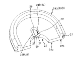
図10〜図13に前記グロメット19を詳細に示す。グロメット19は、例えばゴム若しくは軟質プラスチック等の弾性材にて平面視で略長円状に成形されている。該グロメット19は、中央の分割ラインLを境にして、互いに対称形を成すグロメット半体19Aと19Bの2つに分割されており、この2つに分割されたグロメット半体19A,19Bの各対向面20,20を互いに突き合わせて、1つの上記略長円状のグロメット19に組み合わせて使用される。
10 to 13 show the
前記グロメット19は、中央部19aが比較的厚肉(例えば12ミリ)に形成されるとともに、この中央部19aに対して外周部19bがさらに厚肉(例えば21ミリ)に形成されている。また、グロメット19の外周部19bには、隔壁7の貫通孔8に嵌り合う溝部21が形成されている。
The
前記グロメット19の中央部には、前記ホース6eを挿通させるためのホース挿通孔22が設けられている。また、該ホース挿入孔22を挟んだ前後の位置には、目隠し孔23,23が設けられている。なお、ホース挿通孔22の中心は前記分割ラインL上に設けられ、ホース挿通孔22の半円部がグロメット半体9Aと9Bにそれぞれ対称な形で形成されている。
A
目隠し孔23は、薄肉(例えば3ミリ)の膜状をした蓋片部24により閉じられている孔である。蓋片部24は、目隠し孔23の中心を通る十字形の切り込み、すなわち目隠し孔23の中心から内周縁に向かって放射状に延びる切り込み25により、4つの小片24a,24a…に分割されており、各小片24a,24a…の先端側が弾性変形により上下方向に揺動できるようになっている。なお、各小片24a,24a…は、目隠し孔23にホース6fが挿入されていないとき、自己弾性復帰力で目隠し孔23を閉じ、外部からの塵埃や音の侵入を防ぐ。
The
また、グロメット19の裏面側における中央部には、図12に示すように、ホース挿入孔22と目隠し孔23との間に、比較的薄肉(例えば4ミリ)のリブ部27,27が、目隠し孔23の切り込み25に通じる切り込み26で左右に分割された状態にして形成されている。この1対のリブ部27,27は、薄肉膜状の蓋片部24がホース6fの周面に弾発的に当接されて該ホース6fを抱持するとき、変形されずに薄肉の蓋片部24だけがめくれ上がるようにする役目をする。
Further, as shown in FIG. 12, relatively thin-walled (for example, 4 mm)
このような構成において、隔壁7の貫通孔8を貫通して配管されているホース6eとホース6fをそれぞれ1本ずつ隔壁7に固定する場合は、隔壁7の貫通孔8を貫通して配管されているホース6e,6fのうち、まずホース6fをグロメット半体19Aに取り付ける。該ホース6fの目隠し孔23への取り付けは、リブ部27,27との間の切り込み26を拡げて、グロメット半体19Aの側方からホース26fを挿入することにより取り付けることができる。
In such a configuration, when one hose 6e and one
また、このホース6fの挿入により蓋片部24の小片24a,24a…は、図9及び図13中に2点鎖線で示すように、上方向に逃がされ、ホース6fの周面に弾発的に当接して該ホース6fを抱持し、該ホース6fと目隠し孔23との間の隙間や該隙間によるズレを吸収する。これにより、一方のグロメット半体19Aがホース6fに取り付けられる。
Further, by inserting this
次いで、グロメット半体19Aのホース挿入孔22にホース6eを対応させ、さらに該グロメット半体19Aの対向面20にグロメット半体19Bの対向面20を突き合わせる。これにより、図9に示すように、ホース挿通孔22にホース6eが挿入された1つのグロメット19が組み立てられる。
Next, the hose 6e is made to correspond to the
続いて、グロメット19を隔壁7の貫通孔8にはめ込み、貫通孔8の内周縁部を溝部21に嵌合させると、グロメット19がホース6e,6fと共に隔壁7に保持される。
Subsequently, when the
なお、挿通させるホース6fの本数が増えた場合には、グロメット半体19B側の目隠し孔23を使用してホース6fを1本だけ追加させることができる。
When the number of
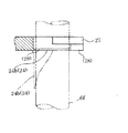
図14〜図17は、上記実施例2のグロメット半体19A,19Bでなるグロメット19における目隠し孔23の変形例を示すものである。図14〜図17において、図9〜図13に示した構成と対応する部分は、同じ符号を付して説明する。この変形例では、リブ部27,27との間に設けた切り込み28と連続した形で、蓋片部24に目隠し孔23を横切る1本の切り込み29を設けるとともに、さらにリブ部27,27と蓋片部24との間に目隠し孔23の内周に沿って半円以上の切り込み30を設けて、リブ部27,27と蓋片部24との間を分離させたものである。このような構造にしても、目隠し孔23にホース6fを挿通させた際に、蓋片部24の小片24b,24bだけがめくれるようにすることもできる。
14 to 17 show modified examples of the
なお、本発明は上記以外にも、本発明の精神を逸脱しない限り種々の改変を為すことができ、そして、本発明が該改変されたものに及ぶことは当然である。 In addition to the above, the present invention can be variously modified without departing from the spirit of the present invention, and the present invention naturally extends to the modified ones.
6a〜6f ホース(紐状体または棒状体)
7 隔壁
8 貫通孔
9 グロメット
9A,9B グロメット半体
9a 中央部
9b 外周部
10 対向面
11 溝部
12〜15 ホース挿通孔
13a〜15b 切欠部
16 縁取り部
19 グロメット
19A,19B グロメット半体
22 ホース挿通孔
23 目隠し孔
24 蓋片部
24a 小片
24b 小片
25 切り込み
26 切り込み
27 リブ部
28 切り込み
29 切り込み
30 切り込み
L 分割ライン
6a-6f hose (string or rod)
7 Bulkhead 8 Through-
12 to 15
24a
Claims (6)
前記グロメットを、前記挿通孔を横切るような分割ラインで2分割した分割構造とし、上記挿通孔を、ほぼ真円形状で、かつ、その中心を上記分割ラインからずらして設け、上記2分割されたグロメットの一方の半体側に前記挿通孔を形成している半円以上の平面視C字形状の切欠部を設けたことを特徴とする建設機械のシール構造。 In a seal structure having an insertion hole, and attaching a grommet made of an elastic body in which a string-like body or a rod-like body is inserted into the insertion hole to a through-hole of a partition wall of a construction machine,
The grommet has a split structure that is divided into two by a dividing line that crosses the insertion hole, the insertion hole has a substantially circular shape, and the center thereof is shifted from the dividing line, and is divided into two. A sealing structure for a construction machine, characterized in that a cutout portion having a C-shape in plan view of a semicircle or more forming the insertion hole is provided on one half of the grommet.
Priority Applications (1)
| Application Number | Priority Date | Filing Date | Title |
|---|---|---|---|
| JP2007001658A JP4804366B2 (en) | 2007-01-09 | 2007-01-09 | Construction machine seal structure |
Applications Claiming Priority (1)
| Application Number | Priority Date | Filing Date | Title |
|---|---|---|---|
| JP2007001658A JP4804366B2 (en) | 2007-01-09 | 2007-01-09 | Construction machine seal structure |
Publications (2)
| Publication Number | Publication Date |
|---|---|
| JP2008171595A JP2008171595A (en) | 2008-07-24 |
| JP4804366B2 true JP4804366B2 (en) | 2011-11-02 |
Family
ID=39699502
Family Applications (1)
| Application Number | Title | Priority Date | Filing Date |
|---|---|---|---|
| JP2007001658A Active JP4804366B2 (en) | 2007-01-09 | 2007-01-09 | Construction machine seal structure |
Country Status (1)
| Country | Link |
|---|---|
| JP (1) | JP4804366B2 (en) |
Families Citing this family (8)
| Publication number | Priority date | Publication date | Assignee | Title |
|---|---|---|---|---|
| JP5562763B2 (en) * | 2009-08-27 | 2014-07-30 | 日立建機株式会社 | Construction machinery |
| JP2015039257A (en) * | 2013-05-14 | 2015-02-26 | 美智子 宮下 | Cord bundling device |
| JP6595931B2 (en) * | 2016-02-19 | 2019-10-23 | 株式会社竹内製作所 | Work vehicle |
| EP3656932A4 (en) | 2017-12-27 | 2021-05-12 | Kubota Corporation | Work equipment and method for producing work equipment |
| JP6896604B2 (en) * | 2017-12-27 | 2021-06-30 | 株式会社クボタ | Work machine |
| JP7126989B2 (en) * | 2019-06-26 | 2022-08-29 | 株式会社クボタ | work machine |
| JP2022099946A (en) * | 2020-12-23 | 2022-07-05 | 株式会社オートネットワーク技術研究所 | Wiring module and elastic cutoff member |
| GB202101071D0 (en) * | 2021-01-27 | 2021-03-10 | Agco Int Gmbh | Cable feedthrough assembly for vehicle |
Family Cites Families (6)
| Publication number | Priority date | Publication date | Assignee | Title |
|---|---|---|---|---|
| JPS5892774A (en) * | 1981-11-25 | 1983-06-02 | 株式会社日立製作所 | Foamed door of door for refrigerator |
| JPH0726696Y2 (en) * | 1990-03-19 | 1995-06-14 | 有限会社ニッケンレジテック | Floating diagnosis device for outer wall |
| JP2000040433A (en) * | 1998-07-22 | 2000-02-08 | Sumitomo Wiring Syst Ltd | Grommet |
| JP2001176346A (en) * | 1999-12-15 | 2001-06-29 | Takahashiworks Co Ltd | Seal mechanism of passage part of passing-through things in partition portion of vehicle |
| JP2001288781A (en) * | 2000-04-05 | 2001-10-19 | Komatsu Ltd | Seal structure of operation chamber for construction machine |
| JP2004234883A (en) * | 2003-01-28 | 2004-08-19 | Nissan Motor Co Ltd | Grommet structure |
-
2007
- 2007-01-09 JP JP2007001658A patent/JP4804366B2/en active Active
Also Published As
| Publication number | Publication date |
|---|---|
| JP2008171595A (en) | 2008-07-24 |
Similar Documents
| Publication | Publication Date | Title |
|---|---|---|
| JP4804366B2 (en) | Construction machine seal structure | |
| JP4790286B2 (en) | Steering cover | |
| JP2007203938A (en) | Piping seal member and its manufacturing method | |
| JP6383770B2 (en) | Door hole seal | |
| JPWO2004025152A1 (en) | Vehicle hole cover | |
| JP4751985B2 (en) | Construction machine cab seal structure | |
| JP4773900B2 (en) | Vehicle door structure | |
| JP5920313B2 (en) | Work machine | |
| JP2009528214A (en) | Brake booster and its mounting method | |
| JP2010058621A (en) | Seal structure of roof side door frame | |
| JP2006224840A (en) | Sealing structure for operation tool guide groove | |
| JP5033000B2 (en) | Door weather strip mounting structure | |
| JP2006313396A (en) | Seal structure of operation tool guide groove | |
| US10760331B2 (en) | Sealing device and method of installation | |
| JP6358426B2 (en) | Brake structure of vehicle | |
| JP2007009446A (en) | Sealing structure of cab for construction machinery | |
| JP2004234883A (en) | Grommet structure | |
| JP2004222471A (en) | Sealing structure of cab for construction equipment | |
| JP6958411B2 (en) | Interior materials for vehicles | |
| JP6172527B2 (en) | Interior materials for vehicles | |
| JP2011213270A (en) | Column hole cover | |
| JP4451383B2 (en) | Construction machine cab seal structure | |
| JP2008087718A (en) | Steering joint cover | |
| JP2004216994A (en) | Seal structure of steering shaft cover | |
| WO2020049961A1 (en) | Linking device and sealing device |
Legal Events
| Date | Code | Title | Description |
|---|---|---|---|
| A711 | Notification of change in applicant |
Free format text: JAPANESE INTERMEDIATE CODE: A712 Effective date: 20090623 |
|
| A521 | Written amendment |
Free format text: JAPANESE INTERMEDIATE CODE: A523 Effective date: 20090724 |
|
| A521 | Written amendment |
Free format text: JAPANESE INTERMEDIATE CODE: A523 Effective date: 20090731 |
|
| RD04 | Notification of resignation of power of attorney |
Free format text: JAPANESE INTERMEDIATE CODE: A7424 Effective date: 20091008 |
|
| A977 | Report on retrieval |
Free format text: JAPANESE INTERMEDIATE CODE: A971007 Effective date: 20110223 |
|
| A131 | Notification of reasons for refusal |
Free format text: JAPANESE INTERMEDIATE CODE: A131 Effective date: 20110524 |
|
| A521 | Written amendment |
Free format text: JAPANESE INTERMEDIATE CODE: A523 Effective date: 20110720 |
|
| TRDD | Decision of grant or rejection written | ||
| A01 | Written decision to grant a patent or to grant a registration (utility model) |
Free format text: JAPANESE INTERMEDIATE CODE: A01 Effective date: 20110809 |
|
| A01 | Written decision to grant a patent or to grant a registration (utility model) |
Free format text: JAPANESE INTERMEDIATE CODE: A01 |
|
| A61 | First payment of annual fees (during grant procedure) |
Free format text: JAPANESE INTERMEDIATE CODE: A61 Effective date: 20110809 |
|
| R150 | Certificate of patent or registration of utility model |
Ref document number: 4804366 Country of ref document: JP Free format text: JAPANESE INTERMEDIATE CODE: R150 Free format text: JAPANESE INTERMEDIATE CODE: R150 |
|
| FPAY | Renewal fee payment (event date is renewal date of database) |
Free format text: PAYMENT UNTIL: 20140819 Year of fee payment: 3 |