JP4802948B2 - Load drive control device - Google Patents
Load drive control device Download PDFInfo
- Publication number
- JP4802948B2 JP4802948B2 JP2006238880A JP2006238880A JP4802948B2 JP 4802948 B2 JP4802948 B2 JP 4802948B2 JP 2006238880 A JP2006238880 A JP 2006238880A JP 2006238880 A JP2006238880 A JP 2006238880A JP 4802948 B2 JP4802948 B2 JP 4802948B2
- Authority
- JP
- Japan
- Prior art keywords
- control
- temperature
- current
- transistor
- load
- Prior art date
- Legal status (The legal status is an assumption and is not a legal conclusion. Google has not performed a legal analysis and makes no representation as to the accuracy of the status listed.)
- Expired - Fee Related
Links
Images


Landscapes
- Dc-Dc Converters (AREA)
- Electronic Switches (AREA)
- Protection Of Static Devices (AREA)
- Emergency Protection Circuit Devices (AREA)
- Continuous-Control Power Sources That Use Transistors (AREA)
Description
本発明は負荷駆動制御装置に係り、詳しくは、電源から負荷に供給される駆動電流を制御する電流駆動素子を用いる負荷駆動制御装置に関するものである。 The present invention relates to a load drive control device, and more particularly to a load drive control device using a current drive element for controlling a drive current supplied from a power source to a load.
従来より、電源から負荷に供給される駆動電流を制御する電流駆動素子と、その電流駆動素子の動作を制御する制御手段とを備えた負荷駆動制御装置が広く使用されている。 2. Description of the Related Art Conventionally, a load drive control device including a current drive element that controls a drive current supplied from a power supply to a load and a control unit that controls the operation of the current drive element has been widely used.
例えば、特許文献1には、nチャネル電界効果トランジスタのソースと接地側との間またはpチャネル電界効果トランジスタのソースと電源側との間にインダクタンス負荷を接続し、このインダクタンス負荷に流れる電流を前記電界効果トランジスタで制御し、前記インダクタンス負荷は電動パワーステアリング装置の補助トルク電動機の電機子コイルである駆動回路が開示されている。
この特許文献1の技術では、電界効果トランジスタを前記電流駆動素子とし、駆動回路を前記制御手段として、電界効果トランジスタをPWM(Pulse Width Modulation)制御することにより、負荷に流れる電流を制御している。
In the technique of Patent Document 1, a field effect transistor is used as the current drive element, a drive circuit is used as the control means, and the field effect transistor is controlled by PWM (Pulse Width Modulation) to control the current flowing through the load. .
負荷駆動制御装置では、電流駆動素子が異常に発熱して温度が過剰に高くなった温度異常時に、電流駆動素子の故障や破壊を防止するための温度保護機能を備える必要がある。
特許文献1の技術では、電動機の電機子コイルが負荷であるため、電流駆動素子である電界効果トランジスタが異常に発熱して故障や破壊が起こる一番の原因として、電動機のモーターロック時に電機子コイルに過大電流が流れ、その過大電流が電流駆動素子にも流れることがあげられる。
In the load drive control device, it is necessary to have a temperature protection function for preventing failure and destruction of the current drive element when the temperature is excessively high due to abnormal heat generation of the current drive element.
In the technique of Patent Document 1, since the armature coil of the motor is a load, the field effect transistor, which is a current driving element, generates heat abnormally and causes failure or destruction. An excessive current flows through the coil, and the excessive current also flows through the current driving element.
そこで、特許文献1の技術における温度保護機能としては、電流駆動素子の温度異常時に電流駆動素子の動作を停止させて負荷への通電をカットする方法が考えられる。尚、特許文献1には、電界効果トランジスタの温度保護機能について一切記載されていない。 Therefore, as a temperature protection function in the technique of Patent Document 1, a method of stopping the operation of the current drive element when the temperature of the current drive element is abnormal and cutting off the power supply to the load can be considered. Patent Document 1 does not describe any temperature protection function of the field effect transistor.
このように、電流駆動素子の動作を停止させて負荷への通電をカットする方法は、電動機の電機子コイルだけでなく、インダクタンス負荷に対して広く使用されている。
しかし、負荷への通電をカットすると、負荷駆動制御装置が機能停止するため、負荷駆動制御装置のユーザーに与える影響が大きいという問題がある。
As described above, the method of stopping the operation of the current driving element and cutting off the power supply to the load is widely used not only for the armature coil of the electric motor but also for the inductance load.
However, if the power supply to the load is cut off, the load drive control device stops functioning, and there is a problem that the influence on the user of the load drive control device is large.
ところで、インダクタンス負荷ではなく、抵抗体の負荷(抵抗負荷)の場合には、デッドショートを含まない通常使用状態では過大電流が流れないという性質が抵抗負荷にあるため、モーターロック時に電機子コイルに流れる過大電流のような大きな電流が抵抗負荷に流れることはない。
ちなみに、抵抗負荷としては、各種ヒーター(例えば、PTC(Positive Temperature Coefficient)ヒーター、ニッケルクロム線ヒーター、鉄クロム線ヒーターなど)がある。特に、PTCヒーターは、ヒーター自身が温度に応じて流れる電流を制御するため、負荷として好適である。
By the way, in the case of a resistor load (resistive load) instead of an inductance load, the resistance load has the property that an excessive current does not flow in a normal use state that does not include a dead short. A large current such as an excessive current flowing does not flow through the resistive load.
Incidentally, as the resistive load, there are various heaters (for example, PTC (Positive Temperature Coefficient) heater, nickel chrome wire heater, iron chrome wire heater, etc.). In particular, the PTC heater is suitable as a load because the heater itself controls the current flowing according to the temperature.
従って、抵抗負荷の場合には、電流駆動素子の動作を停止させて負荷への通電をカットする方法を使用する必要がない。
そこで、抵抗負荷の場合に、負荷への通電をカットすることなく電流駆動素子を故障や破壊から保護する技術が要求されている。
Therefore, in the case of a resistive load, there is no need to use a method of stopping the operation of the current drive element and cutting off the current supply to the load.
Therefore, in the case of a resistive load, there is a demand for a technique that protects the current drive element from failure and destruction without cutting off the power supply to the load.
本発明は上記要求を満足させるためになされたものであって、その目的は、電流駆動素子の温度異常時にも負荷への通電を継続させた上で、電流駆動素子を確実に保護可能な負荷駆動制御装置を提供することにある。 The present invention has been made in order to satisfy the above-described requirements. The purpose of the present invention is to provide a load that can reliably protect the current drive element while continuing to energize the load even when the temperature of the current drive element is abnormal. To provide a drive control device.
請求項1に記載の発明は、
電源(11)から負荷(17)に供給される駆動電流を制御する電流駆動素子(21)と、
前記電流駆動素子の動作を制御する制御手段(15,22,23)と、
前記電流駆動素子の温度を直接的または間接的に検出する温度センサ(25)と、
その温度センサの検出結果に基づいて、前記電流駆動素子が異常に発熱して温度が過剰に高くなっている温度異常状態かどうかを判定し、温度異常状態と判定した場合には、前記電流駆動素子の電力損失が低減するような制御を前記制御手段に実行させる保護手段(24)とを備え、
前記負荷(17)は、デッドショートを含まない通常使用状態では過大電流が流れない性質を有するヒーターであり、
前記保護手段(24)は、温度異常状態と判定した際に、前記制御手段(15,22,23)が前記電流駆動素子(21)の通常制御中であれば、前記電流駆動素子がフルオン固定状態になるような制御を前記制御手段に実行させる負荷駆動制御装置(10)をその技術的特徴とする。
The invention described in claim 1
A current driving element (21) for controlling a driving current supplied from the power source (11) to the load (17);
Control means (15, 22, 23) for controlling the operation of the current drive element;
A temperature sensor (25) for directly or indirectly detecting the temperature of the current drive element;
Based on the detection result of the temperature sensor, it is determined whether or not the current drive element is abnormally heated and the temperature is excessively high, and if it is determined that the temperature is abnormal, the current drive Protective means (24) for causing the control means to execute control that reduces power loss of the element,
It said load (17), Ri heater der having a property of an excessive current does not flow in the normal use state free of a dead short,
When the protection means (24) determines that the temperature is abnormal, if the control means (15, 22, 23) is under normal control of the current drive element (21), the current drive element is fixed at full on. The technical feature of the load drive control device (10) that causes the control means to execute the control to be in a state .
請求項2に記載の発明は、
請求項1に記載の負荷駆動制御装置において、
前記制御手段(15,22,23)は、前記通常制御中には前記電流駆動素子(21)をPWM制御し、
前記保護手段(24)は、温度異常状態と判定した際に、前記制御手段(15,22,23)が前記電流駆動素子(21)の通常制御中でない場合には、前記電流駆動素子をフルオン固定状態にした場合よりも電力損失が低損失になるような制御を前記制御手段に実行させることを技術的特徴とする。
The invention described in claim 2
The load drive control device according to claim 1 ,
The control means (15, 22, 23) performs PWM control on the current drive element (21) during the normal control,
When the protection means (24) determines that the temperature is abnormal, and the control means (15, 22, 23) is not in the normal control of the current drive element (21), the current drive element is fully turned on. A technical feature is that the control means executes control such that power loss is lower than that in a fixed state.
請求項3に記載の発明は、
請求項2に記載の負荷駆動制御装置において、
前記電力損失が低損失になるような制御は、前記電流駆動素子(21)を制御するための制御信号のデュ−ティ比を低い値に設定した制御か、または、前記制御信号のスイッチング周波数を低い値に設定した制御であることを技術的特徴とする。
The invention according to claim 3
In the load drive control device according to claim 2 ,
The control for reducing the power loss is a control in which the duty ratio of the control signal for controlling the current driving element (21) is set to a low value , or the switching frequency of the control signal is changed. The technical feature is that the control is set to a low value.
請求項4に記載の発明は、
請求項1に記載の負荷駆動制御装置において、
前記制御手段(15,22,23)は、前記通常制御中には前記電流駆動素子(21)をリニア制御し、
前記保護手段(24)は、温度異常状態と判定した際に、前記制御手段(15,22,23)が前記電流駆動素子(21)の通常制御中でない場合には、前記電流駆動素子をフルオン固定状態にした場合よりも電力損失が低損失になるような制御を前記制御手段に実行させることを技術的特徴とする。
The invention according to claim 4
The load drive control device according to claim 1 ,
The control means (15, 22, 23) linearly controls the current drive element (21) during the normal control ,
When the protection means (24) determines that the temperature is abnormal, and the control means (15, 22, 23) is not in the normal control of the current drive element (21), the current drive element is fully turned on. A technical feature is that the control means executes control such that power loss is lower than that in a fixed state .
<請求項1:第1実施形態または第2実施形態に該当(図1〜図3参照)>
請求項1の発明において、温度センサ(25)が電流駆動素子(21)の温度を直接的に検出するには、電流駆動素子を形成する半導体チップに温度センサを取付固定する。
また、温度センサが電流駆動素子の温度を間接的に検出するには、温度センサを電流駆動素子のパッケージに取付固定するか又はパッケージの近傍に配置しておき、パッケージの温度またはパッケージ周辺の温度を検出する。
<Claim 1: Corresponds to the first embodiment or the second embodiment (see FIGS. 1 to 3)>
In the invention of claim 1, in order for the temperature sensor (25) to directly detect the temperature of the current drive element (21), the temperature sensor is attached and fixed to the semiconductor chip forming the current drive element.
In addition, in order for the temperature sensor to indirectly detect the temperature of the current driving element, the temperature sensor is mounted and fixed to the package of the current driving element or arranged near the package, and the temperature of the package or the temperature around the package is set. Is detected.
保護手段(24)は、電流駆動素子が異常に発熱して温度が過剰に高くなっている温度異常状態かどうかを判定する方法として、例えば、温度センサが検出した温度が所定のしきい値を超えたかどうかを判定する方法や、当該温度が所定のしきい値を超えた状態が所定時間以上継続しているかどうか判定する方法などを用いる。 The protection means (24) is, for example, a method for determining whether or not the temperature of the current drive element is abnormally high and the temperature is excessively high. For example, the temperature detected by the temperature sensor has a predetermined threshold value. For example, a method for determining whether or not the temperature has exceeded a predetermined threshold value is used.
そして、保護手段は、温度異常状態と判定した場合には(S101,S201:Yes)、電流駆動素子の電力損失が低減するような制御(S103,S104,S203,S204)を制御手段(15,22,23)に実行させることにより、電流駆動素子の発熱を抑制させて温度を低下させる。
その結果、電流駆動素子の温度異常状態が解消されて正常状態に戻ると、保護手段は温度異常状態ではないと判定するため、制御手段は電流駆動素子を通常制御に戻す。
When the protection means determines that the temperature is abnormal (S101, S201: Yes), the control means (15, S104, S203, S204) controls the power loss of the current drive elements to be reduced (S103, S104, S203, S204). 22 and 23), the heat generation of the current drive element is suppressed and the temperature is lowered.
As a result, when the abnormal temperature state of the current driving element is resolved and the normal state is restored, the protection unit determines that the temperature driving state is not abnormal, so that the control unit returns the current driving element to the normal control.
請求項1の発明では、デッドショートを含まない通常使用状態では過大電流が流れない性質を有する負荷を駆動している。そのため、負荷の通常使用状態では、モーターロック時に電機子コイルに流れる過大電流のような大きな電流が負荷に流れることはない。
従って、請求項1の発明によれば、電流駆動素子の温度異常時でも、電流駆動素子をフルオフ固定状態にして動作を停止させることにより負荷への通電をカットする方法を使用する必要がない。
According to the first aspect of the present invention, a load having a property that an excessive current does not flow in a normal use state not including a dead short is driven. Therefore, in a normal use state of the load, a large current such as an excessive current flowing in the armature coil when the motor is locked does not flow to the load.
Therefore, according to the first aspect of the present invention, even when the temperature of the current drive element is abnormal, it is not necessary to use a method of cutting off the power supply to the load by stopping the operation with the current drive element in the full-off fixed state.
そして、請求項1の発明によれば、保護手段および温度センサを設け、電流駆動素子の温度異常時には電流駆動素子の電力損失を低減させる制御を実行するため、電流駆動素子の温度異常時にも負荷への通電を継続させた上で、電流駆動素子を確実に保護可能な負荷駆動制御装置を実現できる。 According to the first aspect of the present invention, the protection means and the temperature sensor are provided, and control is performed to reduce the power loss of the current drive element when the temperature of the current drive element is abnormal. It is possible to realize a load drive control device capable of reliably protecting the current drive element while continuing energization of the current drive element.
尚、デッドショートを含まない通常使用状態では過大電流が流れない性質を有する負荷には、例えば、抵抗負荷である各種ヒーター(PTCヒーター、ニッケルクロム線ヒーター、鉄クロム線ヒーターなど)がある。特に、PTCヒーターは、ヒーター自身が温度に応じて流れる電流を制御するため、負荷として好適である。 Examples of loads having a property that an excessive current does not flow in a normal use state that does not include a dead short include various heaters (PTC heaters, nickel chrome wire heaters, iron chrome wire heaters, etc.) that are resistive loads. In particular, the PTC heater is suitable as a load because the heater itself controls the current flowing according to the temperature.
また、請求項1の発明において、保護手段(24)は、温度異常状態と判定した際に(S101,S201:Yes)、制御手段(15,22,23)が電流駆動素子(21)の通常制御中であれば(S102,S202:Yes)、電流駆動素子がフルオン固定状態になるような制御(S103,S203)を制御手段に実行させる。
In the first aspect of the invention, when the protection means (24) determines that the temperature is abnormal (S101, S201: Yes), the control means (15, 22, 23) is the normal state of the current drive element (21). If control is in progress (S102, S202: Yes), the control means is caused to execute control (S103, S203) such that the current drive element is in the full-on fixed state.
このように、電流駆動素子がフルオン固定状態に制御されると、電流駆動素子の電力損失が低減され、電流駆動素子の発熱が抑制されて温度が低下する。
その結果、電流駆動素子の温度異常状態が解消されて正常状態に戻ると、保護手段は温度異常状態ではないと判定するため、制御手段は電流駆動素子を通常制御に戻す。
従って、請求項1の発明によれば、請求項1の作用・効果を確実に得られる。
As described above, when the current driving element is controlled to be in the full-on fixed state, the power loss of the current driving element is reduced, the heat generation of the current driving element is suppressed, and the temperature is lowered.
As a result, when the abnormal temperature state of the current driving element is resolved and the normal state is restored, the protection unit determines that the temperature driving state is not abnormal, so that the control unit returns the current driving element to the normal control.
Therefore, according to the invention of claim 1, obtained reliably yield the actions and effects of claim 1.
<請求項2:第1実施形態に該当(図2参照)>
請求項2の発明によれば、制御手段(15,22,23)が電流駆動素子(21)をPWM制御する負荷駆動制御装置を実現できる。
請求項2の発明において、保護手段(24)は、温度異常状態と判定した際に(S101:Yes)、制御手段(15,22,23)が電流駆動素子(21)を通常制御中でない場合には(S102:No)、電流駆動素子をフルオン固定状態にした場合よりも電力損失が低損失になるような制御(S104)を制御手段に実行させる。
尚、通常制御中でない場合とは、フルオン固定状態に制御中ということである。
< Claim 2 : Corresponds to the first embodiment (see FIG. 2) >
According to the invention of claim 2, it is possible to realize a load drive control device in which the control means (15, 22, 23) performs PWM control of the current drive element (21).
In the invention of claim 2 , when the protection means (24) determines that the temperature is abnormal (S101 : Yes), the control means (15, 22, 23) does not normally control the current drive element (21). (S102 : No), the control means executes control (S104 ) such that the power loss is lower than when the current drive element is in the full-on fixed state.
The case where the normal control is not being performed means that the control is being performed in the full-on fixed state.
このように、電流駆動素子をフルオン固定状態にした場合よりも電力損失が低損失になるように制御されると、電流駆動素子の電力損失が更に低減され、電流駆動素子の発熱が抑制されて温度が低下する。
その結果、電流駆動素子の温度異常状態が解消されて正常状態に戻ると、保護手段は温度異常状態ではないと判定するため、制御手段は電流駆動素子を通常制御に戻す。
従って、請求項2の発明によれば、請求項1の作用・効果を更に確実に得られる。
In this way, when the current loss is controlled to be lower than when the current drive element is in the full-on fixed state, the power loss of the current drive element is further reduced, and the heat generation of the current drive element is suppressed. The temperature drops.
As a result, when the abnormal temperature state of the current driving element is resolved and the normal state is restored, the protection unit determines that the temperature driving state is not abnormal, so that the control unit returns the current driving element to the normal control.
Therefore, according to the invention of claim 2 , the operation and effect of claim 1 can be obtained more reliably.
<請求項3:第1実施形態に該当(図2参照)>
請求項3の発明では、電流駆動素子をフルオン固定状態にした場合よりも電力損失(スイッチング損失)が低損失になるような制御として、電流駆動素子を制御するための制御信号のデューティ比を低い値(低デューティ側)に設定した制御、または、当該制御信号のスイッチング周波数を低い値に設定した制御を行う。
ここで、デューティ比やスイッチング周波数の具体値は、電流駆動素子のスイッチング損失が十分に低減されるように、カット・アンド・トライで実験的に最適値を見つけて設定すればよい。
< Claim 3: Corresponds to the first embodiment (see FIG. 2) >
In the invention of claim 3, the power loss than the case where the current-driven elements in the full-on fixed state (switching loss) as a control such that a low loss, low duty ratio of the control signal for controlling the current driven element The control set to the value (low duty side) or the control set to the low value of the switching frequency of the control signal is performed.
Here, the specific values of the duty ratio and the switching frequency may be set by experimentally finding optimum values by cut-and-try so that the switching loss of the current drive element is sufficiently reduced.
<請求項4:第2実施形態に該当(図3参照)>
請求項4の発明によれば、制御手段(15,22,23)が電流駆動素子(21)をリニア制御する負荷駆動制御装置を実現できる。
請求項4の発明において、保護手段(24)は、温度異常状態と判定した際に(S201:Yes)、制御手段(15,22,23)が電流駆動素子(21)を通常制御中でない場合には(S202:No)、電流駆動素子をフルオン固定状態にした場合よりも電力損失が低損失になるような制御(S204)を制御手段に実行させる。
尚、通常制御中でない場合とは、フルオン固定状態に制御中ということである。
このように、電流駆動素子をフルオン固定状態にした場合よりも電力損失が低損失になるように制御されると、電流駆動素子の電力損失が更に低減され、電流駆動素子の発熱が抑制されて温度が低下する。
その結果、電流駆動素子の温度異常状態が解消されて正常状態に戻ると、保護手段は温度異常状態ではないと判定するため、制御手段は電流駆動素子を通常制御に戻す。
従って、請求項4の発明によれば、請求項1の作用・効果を更に確実に得られる。
ちなみに、電流駆動素子をフルオン固定状態にした場合よりも電力損失が低損失になるような制御とは、例えば、電流駆動素子がPチャネルMOSトランジスタの場合には、電流駆動素子を制御するための制御信号の電圧値を高い値に設定した制御であり、電流駆動素子がNチャネルMOSトランジスタの場合には当該制御信号の電圧値を低い値に設定した制御である。
ここで、制御信号の電圧値の具体値は、電流駆動素子の電力損失が十分に低減されるように、カット・アンド・トライで実験的に最適値を見つけて設定すればよい。
< Claim 4: Corresponds to the second embodiment (see FIG. 3) >
According to the invention of claim 4 , it is possible to realize a load drive control device in which the control means (15, 22, 23) linearly controls the current drive element (21).
In the invention of claim 4, when the protection means (24) determines that the temperature is abnormal (S201: Yes), the control means (15, 22, 23) is not normally controlling the current drive element (21). (S202: No), the control means is caused to execute control (S204) such that the power loss is lower than that in the case where the current driving element is in the full-on fixed state.
The case where the normal control is not being performed means that the control is being performed in the full-on fixed state.
In this way, when the current loss is controlled to be lower than when the current drive element is in the full-on fixed state, the power loss of the current drive element is further reduced, and the heat generation of the current drive element is suppressed. The temperature drops.
As a result, when the abnormal temperature state of the current driving element is resolved and the normal state is restored, the protection unit determines that the temperature driving state is not abnormal, so that the control unit returns the current driving element to the normal control.
Therefore, according to the invention of claim 4, the operation and effect of claim 1 can be obtained more reliably.
Incidentally, the control that lowers the power loss than when the current drive element is in the full-on fixed state is, for example, when the current drive element is a P-channel MOS transistor, for controlling the current drive element. In this control, the voltage value of the control signal is set to a high value. When the current driving element is an N-channel MOS transistor, the voltage value of the control signal is set to a low value.
Here, the specific value of the voltage value of the control signal may be set by experimentally finding an optimum value by cut-and-try so that the power loss of the current drive element is sufficiently reduced.
<用語の説明>
上術した[課題を解決するための手段][発明の効果]に記載した( )内の符号等は、後述する[発明を実施するための最良の形態]に記載した構成部材・構成要素の符号等に対応したものである。
そして、[課題を解決するための手段][発明の効果]に記載した構成部材・構成要素と、[発明を実施するための最良の形態]に記載した構成部材・構成要素との対応関係は以下のようになっている。
<Explanation of terms>
Reference numerals in parentheses described in [Means for Solving the Problems] and [Effects of the Invention] described above are the same as those of the components and components described in [Best Mode for Carrying Out the Invention] described later. It corresponds to a code or the like.
The correspondence between the constituent members and constituent elements described in [Means for Solving the Problems] and [Effects of the Invention] and the constituent members and constituent elements described in [Best Mode for Carrying Out the Invention] is as follows: It is as follows.
「負荷」は、PTCヒーター17に該当する。
「電流駆動素子」は、Pチャネル・パワーMOSトランジスタ21に該当する。
「制御手段」は、ECU15,駆動回路22,入力信号処理回路23に該当する。
請求項1〜3の「保護手段」は、保護回路24に該当する。
“Load” corresponds to the
The “current driving element” corresponds to the P-channel
The “control means” corresponds to the
The “protection means” in claims 1 to 3 corresponds to the
以下、本発明を具体化した各実施形態について図面を参照しながら説明する。尚、各実施形態において、同一の構成部材および構成要素については符号を等しくすると共に、同一内容の箇所については重複説明を省略してある。 Hereinafter, embodiments embodying the present invention will be described with reference to the drawings. In each embodiment, the same constituent members and constituent elements are denoted by the same reference numerals, and redundant description of the same content is omitted.
<第1実施形態>
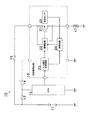
図1は、第1実施形態の負荷駆動制御装置10の概略構成を示すブロック回路図である。
負荷駆動制御装置10は、直流電源11、ヒューズ12,13、イグニッションスイッチ14、電子制御装置(ECU:Electrical Control Unit)15、制御駆動回路16から構成され、直流電源11から抵抗負荷であるPTCヒーター17に供給される駆動電流を制御してPTCヒーター17を駆動制御する。
<First Embodiment>
FIG. 1 is a block circuit diagram showing a schematic configuration of a load
The load
ECU15は、ヒューズ13を介して直流電源11のプラス側端子に接続されると共に、アースラインを介して直流電源11のマイナス側端子に接続され、直流電源11から電源が供給されている。
そして、ECU15は、トランジスタ21をPWM制御するための制御信号を生成して出力する。尚、第1実施形態の制御信号は、ハイレベルとロウレベルが所定周期で切り替わる矩形波のスイッチング信号(PWM信号)である。
The
Then, the
PTCヒーター17は、例えば、自動車に搭載されたエアーコンディショナー(カーエアコン)の暖房用ヒーターである。その場合、直流電源11は車載バッテリであり、ECU15は車載ECUであり、アースラインは車体アースである。
The
制御駆動回路16は、電流駆動素子であるPチャネル・パワーMOSトランジスタ(負荷駆動用トランジスタ)21、駆動回路22、入力信号処理回路23、保護回路24、温度センサ25などから構成されている。
トランジスタ21のゲートは駆動回路22に接続され、トランジスタ21のドレインはPTCヒーター17からアースラインを介して直流電源11のマイナス側端子に接続され、トランジスタ21のソースはヒューズ12を介して直流電源11のプラス側端子に接続されている。
The
The gate of the
制御駆動回路16は、イグニッションスイッチ14からヒューズ13を介して直流電源11のプラス側端子に接続されると共に、アースラインを介して直流電源11のマイナス側端子に接続され、直流電源11から電源が供給されている。
The
入力信号処理回路23は、ECU15から出力された制御信号を、駆動回路22を制御するための制御信号に変換する入力インターフェースである。
保護回路24は、温度センサ25の検出結果に基づいて、後述するトランジスタ21の温度保護機能の動作を実行する。
The input
The
温度センサ25は、トランジスタ21を形成する半導体チップ(図示略)に取付固定されており、その半導体チップの温度(チップ温度)を計測することにより、トランジスタ21の温度を直接的に検出する。
尚、温度センサ25をトランジスタ21のパッケージに取付固定するか又はパッケージの近傍に配置しておき、パッケージの温度またはパッケージ周辺の温度を計測することにより、トランジスタ21の温度を間接的に検出するようにしてもよい。
The
The
駆動回路22は、入力信号処理回路23または保護回路24から出力された制御信号に基づいて、トランジスタ21を駆動するための駆動信号を生成し、その駆動信号をトランジスタ21のゲートへ出力する。
トランジスタ21がON(オン)すると、トランジスタ21を介して直流電源11からPTCヒーター17に駆動電流が供給され、PTCヒーター17が加熱される。また、トランジスタ21がOFF(オフ)すると、トランジスタ21を介して直流電源11からPTCヒーター17に供給されていた駆動電流が停止され、PTCヒーター17の加熱も停止される。つまり、トランジスタ21は、直流電源11から抵抗負荷であるPTCヒーター17に供給される駆動電流を制御する。
The
When the
そのため、ECU15および各回路22〜24が制御信号および駆動信号に基づいてトランジスタ21のON/OFF(オンオフ)動作を切り替えてPWM制御することにより、PTCヒーター17に供給される駆動電流が制御され、PTCヒーター17の温度を所望の値にすることができる。
Therefore, the
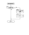
図2は、第1実施形態において保護回路24が実行する温度保護機能の動作を説明するためのフローチャートである。
保護回路24は、以下の各ステップ(以下、「S」と記載する)の処理を実行する。
FIG. 2 is a flowchart for explaining the operation of the temperature protection function performed by the
The
まず、保護回路24は、温度センサ25の検出結果に基づいて、トランジスタ21が異常に発熱して温度が過剰に高くなっている温度異常状態かどうかを判定する(S101)。
尚、温度異常状態の判定方法には、例えば、温度センサ25が検出した温度が所定のしきい値を超えたかどうかを判定する方法や、当該温度が所定のしきい値を超えた状態が所定時間以上継続しているかどうか判定する方法などがある。
First, based on the detection result of the
As a method for determining an abnormal temperature state, for example, a method for determining whether the temperature detected by the
そして、保護回路24は、温度異常状態ではないと判定した場合には(S101:No)、再びS101の処理に戻る。
すなわち、保護回路24が温度異常状態ではなくトランジスタ21の温度が正常であると判定した場合、入力信号処理回路23は、ECU15が生成した制御信号を駆動回路22へ出力する。そして、駆動回路22は、ECU15が生成した制御信号に基づいて、トランジスタ21をPWM制御するための駆動信号を生成し、その駆動信号をトランジスタ21のゲートへ出力する。
そのため、第1実施形態において、温度異常状態でない正常状態(通常状態)の場合、トランジスタ21はPWM制御される。つまり、第1実施形態において、PWM制御は通常制御といえる。
If the
That is, when the
Therefore, in the first embodiment, the
また、保護回路24は、温度異常状態であると判定した場合には(S101:Yes)、入力信号処理回路23の制御信号に基づいて、トランジスタ21がPWM制御中であるかどうかを判定する(S102)。
If the
そして、保護回路24は、トランジスタ21がPWM制御中であると判定した場合には(S102:Yes)、トランジスタ21をフルON固定状態に制御させ(S103)、その後にS101の処理に戻る。
すなわち、保護回路24は、S103の処理にて、トランジスタ21をフルON(フルオン)固定状態にするための制御信号を生成し、その制御信号を駆動回路22へ出力する。すると、駆動回路22は、入力信号処理回路23から出力された制御信号ではなく、保護回路24が生成した制御信号に基づいて、トランジスタ21をフルON固定状態にするための駆動信号を生成し、その駆動信号をトランジスタ21のゲートへ出力する。
When the
That is, the
このように、トランジスタ21がフルON固定状態に制御されると、トランジスタ21のスイッチング損失が低減され、トランジスタ21の発熱が抑制されて温度が低下する。そして、S101〜S103の処理を繰り返すことにより、トランジスタ21の温度異常状態が解消されて正常状態に戻ると、保護回路24はS101の処理にて温度異常状態ではないと判定するため、トランジスタ21はフルON固定状態の制御からPWM制御(通常制御)へ移行する。
尚、第1実施形態において、トランジスタ21をフルON固定状態にするための制御信号とは、デューティ比(ON Duty)が100%の制御信号である。
Thus, when the
In the first embodiment, the control signal for setting the
また、保護回路24は、トランジスタ21がPWM制御中ではないと判定した場合には(S102:No)、トランジスタ21を低損失制御させ(S104)、その後にS101の処理に戻る。尚、第1実施形態において、PWM制御中でない場合とは、フルON固定状態の制御中ということである。
すなわち、保護回路24は、S104の処理にて、トランジスタ21をフルON固定状態にした場合よりもスイッチング損失が低損失になるような制御信号を生成し、その制御信号を駆動回路22へ出力する。すると、駆動回路22は、入力信号処理回路23から出力された制御信号ではなく、保護回路24が生成した制御信号に基づいて、トランジスタ21を低損失制御するための駆動信号を生成し、その駆動信号をトランジスタ21のゲートへ出力する。
When the
In other words, the
このように、トランジスタ21が低損失制御されると、トランジスタ21のスイッチング損失が低減され、トランジスタ21の発熱が抑制されて温度が低下する。そして、S101,S102,S104の処理を繰り返すことにより、トランジスタ21の温度異常状態が解消されて正常状態に戻ると、保護回路24はS101の処理にて温度異常状態ではないと判定するため、トランジスタ21は低損失制御からPWM制御(通常制御)へ移行する。
Thus, when the
尚、トランジスタ21をフルON固定状態にした場合よりもスイッチング損失が低損失になるような制御信号とは、例えば、デューティ比を低い値(低デューティ側)に設定した制御信号や、スイッチング周波数を低い値に設定した制御信号などである。
ここで、制御信号のデューティ比やスイッチング周波数の具体値は、トランジスタ21のスイッチング損失が十分に低減されるように、カット・アンド・トライで実験的に最適値を見つけて設定すればよい。
Note that the control signal in which the switching loss is lower than when the
Here, the specific values of the duty ratio and the switching frequency of the control signal may be set by experimentally finding optimum values by cut-and-try so that the switching loss of the
以上詳述したように、第1実施形態の負荷駆動制御装置10は、PTCヒーター17を抵抗負荷としているため、PTCヒーター17のデッドショートを含まない通常使用状態では、モーターロック時に電機子コイルに流れる過大電流のような大きな電流がPTCヒーター17に流れることはない。
As described above in detail, the load
従って、第1実施形態によれば、トランジスタ21が異常に発熱して温度が過剰に高くなった温度異常時でも、トランジスタ21をフルOFF(フルオフ)固定状態にして動作を停止させることによりPTCヒーター17への通電をカットする方法を使用する必要がない。
Therefore, according to the first embodiment, even when the temperature of the
そして、第1実施形態によれば、保護回路24および温度センサ25を設け、図2に示す温度保護機能動作を実行するため、トランジスタ21の温度異常時にもPTCヒーター17への通電を継続させた上で、トランジスタ21を確実に保護可能な負荷駆動制御装置10を実現できる。
According to the first embodiment, the
<第2実施形態>
第2実施形態の負荷駆動制御装置10の構成は、図1に示した第1実施形態と同じである。
第2実施形態において、第1実施形態と異なるのは、ECU15および保護回路24の動作だけである。
Second Embodiment
The configuration of the load
The second embodiment differs from the first embodiment only in the operations of the
第2実施形態のECU15は、トランジスタ21をリニア制御するための制御信号を生成して出力する。尚、第2実施形態の制御信号は、電圧値がリニアに変化する信号である。
The
図3は、第2実施形態において保護回路24が実行する温度保護機能の動作を説明するためのフローチャートである。
まず、保護回路24は、第1実施形態のS101の処理と同じく、温度センサ25の検出結果に基づいて、トランジスタ21が異常に発熱して温度が過剰に高くなっている温度異常状態かどうかを判定する(S201)。
そして、保護回路24は、温度異常状態ではないと判定した場合には(S201:No)、再びS201の処理に戻る。
FIG. 3 is a flowchart for explaining the operation of the temperature protection function performed by the
First, similarly to the processing of S101 of the first embodiment, the
If the
また、保護回路24は、温度異常状態であると判定した場合には(S201:Yes)、入力信号処理回路23の制御信号に基づいて、トランジスタ21がリニア制御中であるかどうかを判定する(S202)。
尚、第2実施形態において、温度異常状態でない正常状態(通常状態)の場合、トランジスタ21はリニア制御される。つまり、第2実施形態において、リニア制御は通常制御といえる。
If the
In the second embodiment, the
そして、保護回路24は、トランジスタ21がリニア制御中であると判定した場合には(S202:Yes)、第1実施形態のS103の処理と同じく、トランジスタ21をフルON固定状態に制御させ(S203)、その後にS201の処理に戻る。
When the
このように、S201〜S203の処理を繰り返すことにより、トランジスタ21の温度異常状態が解消されて正常状態に戻ると、保護回路24はS201の処理にて温度異常状態ではないと判定するため、トランジスタ21はフルON固定状態の制御からリニア制御(通常制御)へ移行する。
尚、第2実施形態において、トランジスタ21をフルON固定状態にするための制御信号とは、トランジスタ21がPチャネルMOSトランジスタであるため、トランジスタ21が完全にONするような低い電圧の制御信号である。
ちなみに、トランジスタ21がNチャネルMOSトランジスタの場合には、トランジスタ21をフルON固定状態にするための制御信号とは、トランジスタ21が完全にONするような高い電圧の制御信号である。
Thus, by repeating the processing of S201 to S203, when the temperature abnormal state of the
In the second embodiment, the control signal for setting the
Incidentally, when the
また、保護回路24は、トランジスタ21がリニア制御中ではないと判定した場合には(S202:No)、トランジスタ21を低損失制御させ(S204)、その後にS201の処理に戻る。尚、第2実施形態において、リニア制御中でない場合とは、フルON固定状態の制御中ということである。
すなわち、保護回路24は、S204の処理にて、トランジスタ21をフルON固定状態にした場合よりも電力損失が低損失になるような制御信号を生成し、その制御信号を駆動回路22へ出力する。すると、駆動回路22は、入力信号処理回路23から出力された制御信号ではなく、保護回路24が生成した制御信号に基づいて、トランジスタ21を低損失制御するための駆動信号を生成し、その駆動信号をトランジスタ21のゲートへ出力する。
If the
That is, the
このように、トランジスタ21が低損失制御されると、トランジスタ21の電力損失が低減され、トランジスタ21の発熱が抑制されて温度が低下する。そして、S201,S202,S204の処理を繰り返すことにより、トランジスタ21の温度異常状態が解消されて正常状態に戻ると、保護回路24はS201の処理にて温度異常状態ではないと判定するため、トランジスタ21は低損失制御からリニア制御(通常制御)へ移行する。
Thus, when the
尚、トランジスタ21をフルON固定状態にした場合よりも電力損失が低損失になるような制御信号とは、トランジスタ21がPチャネルMOSトランジスタであるため、電圧値を高い値に設定した制御信号である。
ここで、制御信号の電圧値の具体値は、トランジスタ21の電力損失が十分に低減されるように、カット・アンド・トライで実験的に最適値を見つけて設定すればよい。
ちなみに、トランジスタ21がNチャネルMOSトランジスタの場合には、トランジスタ21をフルON固定状態にした場合よりも電力損失が低損失になるような制御信号とは、電圧値を低い値に設定した制御信号である。
Note that the control signal that results in a lower power loss than when the
Here, the specific value of the voltage value of the control signal may be set by experimentally finding an optimum value by cut-and-try so that the power loss of the
Incidentally, when the
以上詳述したように、第2実施形態の負荷駆動制御装置10は、第1実施形態と同じく、PTCヒーター17を抵抗負荷としているため、トランジスタ21が異常に発熱して温度が過剰に高くなった温度異常時でも、PTCヒーター17への通電をカットする方法を使用する必要がない。
As described in detail above, since the load
そして、第2実施形態によれば、保護回路24および温度センサ25を設け、図3に示す温度保護機能動作を実行するため、トランジスタ21の温度異常時にもPTCヒーター17への通電を継続させた上で、トランジスタ21を確実に保護可能な負荷駆動制御装置10を実現できる。
According to the second embodiment, the
<第3実施形態>
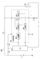
図4は、第3実施形態の負荷駆動制御装置30の概略構成を示すブロック回路図である。
負荷駆動制御装置30は、直流電源11、ヒューズ12,13、イグニッションスイッチ14、電子制御装置15、制御駆動回路16、バイパス用リレー31から構成され、直流電源11から抵抗負荷であるPTCヒーター17に供給される駆動電流を制御してPTCヒーター17を駆動制御する。
そして、制御駆動回路16は、トランジスタ21、駆動回路22、入力信号処理回路23、保護回路24、温度センサ25などから構成されている。
<Third Embodiment>
FIG. 4 is a block circuit diagram showing a schematic configuration of the load
The load
The
第3実施形態の負荷駆動制御装置30において、第1実施形態の負荷駆動制御装置10と異なるのは、以下の点だけである。
[A]バイパス用リレー31は、トランジスタ21のソース・ドレイン間と並列接続され、通常状態ではOFFされており、リレー駆動信号によってONされる。
[B]ECU15は、第1実施形態と同じくトランジスタ21をPWM制御するための制御信号を生成して出力すると共に、後述するトランジスタ21の温度保護機能の動作を実行する。
The load
[A] The
[B] The
図5は、第3実施形態においてECU15,保護回路24,バイパス用リレー31が実行する温度保護機能の動作を説明するためのフローチャートである。
FIG. 5 is a flowchart for explaining the operation of the temperature protection function executed by the
まず、保護回路24は、第1実施形態のS101の処理と同じく、温度センサ25の検出結果に基づいて、トランジスタ21が異常に発熱して温度が過剰に高くなっている温度異常状態かどうかを判定する(S301)。
そして、保護回路24は、温度異常状態ではないと判定した場合には(S301:No)、再びS301の処理に戻る。
First, similarly to the processing of S101 of the first embodiment, the
When the
また、保護回路24は、温度異常状態であると判定した場合には(S301:Yes)、ダイアグ信号を生成してECU15へ出力する。
すると、ECU15は、保護回路24から出力されたダイアグ信号に基づいて、トランジスタ21をPWM制御するための制御信号の生成を停止する(S302)。
その結果、トランジスタ21はフルOFF固定状態になって動作が停止され、トランジスタ21からPTCヒーター17への駆動電流の供給は停止される。
If the
Then, the
As a result, the
次に、ECU15は、保護回路24から出力されたダイアグ信号に基づいて、リレー駆動信号を生成してバイパス用リレー31へ出力し、そのリレー駆動信号によってバイパス用リレー31をONさせ(S303)、その後にS301の処理に戻る。
バイパス用リレー31がONすると、トランジスタ21をバイパスし、バイパス用リレー31を介して直流電源11からPTCヒーター17に駆動電流が供給され、PTCヒーター17が加熱される。
尚、通常状態ではバイパス用リレー31がOFFされているため、バイパス用リレー31を介して直流電源11からPTCヒーター17に電流が流れることはない。
Next, the
When the
In the normal state, since the
S302の処理にてトランジスタ21がフルOFF固定状態にされると、トランジスタ21の温度が低下する。そして、S301〜S303の処理を繰り返すことにより、トランジスタ21の温度異常状態が解消されて正常状態に戻ると、保護回路24はS301の処理にて温度異常状態ではないと判定するため、トランジスタ21はPWM制御(通常制御)へ移行する。
When the
このように、第3実施形態では、トランジスタ21の温度異常時に、トランジスタ21をフルOFF固定状態にして動作を停止させることにより、トランジスタ21からPTCヒーター17への駆動電流の供給を停止させると共に、バイパス用リレーからPTCヒーター17へ駆動電流を供給させる。
As described above, in the third embodiment, when the temperature of the
従って、第3実施形態によれば、ECU15,保護回路24,温度センサ25,バイパス用リレー31を設け、図5に示す温度保護機能動作を実行するため、トランジスタ21の温度異常時にもPTCヒーター17への通電を継続させた上で、トランジスタ21を確実に保護可能な負荷駆動制御装置10を実現できる。
Therefore, according to the third embodiment, the
<第4実施形態>
図6は、第4実施形態の負荷駆動制御装置40の概略構成を示すブロック回路図である。
負荷駆動制御装置40において、第3実施形態の負荷駆動制御装置30と異なるのは、ECU15が温度保護機能の動作に無関係であることと、保護回路24の動作だけである。
<Fourth embodiment>
FIG. 6 is a block circuit diagram showing a schematic configuration of the load
The load
図7は、第4実施形態において保護回路24およびバイパス用リレー31が実行する温度保護機能の動作を説明するためのフローチャートである。
FIG. 7 is a flowchart for explaining the operation of the temperature protection function performed by the
まず、保護回路24は、第1実施形態のS101の処理と同じく、温度センサ25の検出結果に基づいて、トランジスタ21が異常に発熱して温度が過剰に高くなっている温度異常状態かどうかを判定する(S401)。
そして、保護回路24は、温度異常状態ではないと判定した場合には(S401:No)、再びS401の処理に戻る。
First, similarly to the processing of S101 of the first embodiment, the
If the
また、保護回路24は、温度異常状態であると判定した場合には(S401:Yes)、トランジスタ21をフルOFF固定状態に制御させる(S402)。
すなわち、保護回路24は、S402の処理にて、トランジスタ21をフルOFF固定状態にするための制御信号を生成し、その制御信号を駆動回路22へ出力する。すると、駆動回路22は、入力信号処理回路23から出力された制御信号ではなく、保護回路24が生成した制御信号に基づいて、トランジスタ21をフルOFF固定状態にするための駆動信号を生成し、その駆動信号をトランジスタ21のゲートへ出力する。
When the
That is, the
次に、保護回路24は、リレー駆動信号を生成してバイパス用リレー31へ出力し、そのリレー駆動信号によってバイパス用リレー31をONさせ(S403)、その後にS401の処理に戻る。
従って、第4実施形態によれば、第3実施形態と同様の作用・効果が得られる。
Next, the
Therefore, according to the fourth embodiment, the same operation and effect as the third embodiment can be obtained.
<別の実施形態>
本発明は上記各実施形態に限定されるものではなく、以下のように具体化してもよく、その場合でも、上記各実施形態と同等もしくはそれ以上の作用・効果を得ることができる。
<Another embodiment>
The present invention is not limited to the above-described embodiments, and may be embodied as follows. Even in this case, operations and effects equivalent to or higher than those of the above-described embodiments can be obtained.
[1]第3実施形態および第4実施形態では、トランジスタ21をPWM制御している。しかし、第3実施形態および第4実施形態についても、第2実施形態と同様に、トランジスタ21をリニア制御するようにしてもよい。
[1] In the third and fourth embodiments, the
[2]第1実施形態および第2実施形態において、低損失制御(S104,S204)に切り替えてもトランジスタ21の温度が十分に低下しない場合には、トランジスタ21をフルOFF固定状態にして動作を停止させることにより、PTCヒーター17への通電をカットすることで、トランジスタ21を故障や破壊から保護してもよい。
[2] In the first embodiment and the second embodiment, when the temperature of the
[3]上記各実施形態は、直流電源11と負荷としてのPTCヒーター17との間に、PTCヒーター17の駆動電流を制御する電流駆動素子としてのトランジスタ21が接続された構成であり、このような構成は一般に「ハイサイド構成」と呼ばれる。
しかし、上記各実施形態は、負荷としてのPTCヒーター17とアースとの間に、PTCヒーター17の駆動電流を制御する電流駆動素子としてのトランジスタ21が接続された構成に変更してもよく、このような構成は一般に「ローサイド構成」と呼ばれる。
つまり、本発明は、ハイサイド構成とローサイド構成の両方に適用できる。
[3] Each of the above embodiments has a configuration in which the
However, each of the above embodiments may be changed to a configuration in which the
That is, the present invention can be applied to both the high side configuration and the low side configuration.
[4]上記各実施形態は、PTCヒーター17を負荷として用いている。
しかし、本発明は、PTCヒーター17に限らず、抵抗体の負荷(抵抗負荷)であれば、どのような抵抗負荷(例えば、ニッケルクロム線ヒーター、鉄クロム線ヒーターなど)に適用してもよい。
また、本発明は、抵抗負荷に限らず、デッドショートを含まない通常使用状態では過大電流が流れない性質を有する負荷であれば、どのような負荷に適用してもよい。
[4] Each of the above embodiments uses the
However, the present invention is not limited to the
Further, the present invention is not limited to a resistance load, and may be applied to any load as long as it has a property that an excessive current does not flow in a normal use state that does not include a dead short.
[5]Pチャネル・パワーMOSトランジスタ21を、Nチャネル・パワーMOSトランジスタ、PNPトランジスタ、NPNトランジスタに置き換えてもよい。
また、トランジスタ21は、MOSトランジスタやバイポーラトランジスタに限らず、どのような電流駆動素子(例えば、IGBT(Insulated Gate Bipolar Transistor)、SIT(Static Induction Transistor)、サイリスタなど)に置き換えてもよい。
[5] The P-channel
The
10,30,40…負荷駆動制御装置
11…直流電源
12,13…ヒューズ
14…イグニッションスイッチ
15…ECU
16…制御駆動回路
17…PTCヒーター
21…Pチャネル・パワーMOSトランジスタ(電流駆動素子)
22…駆動回路
23…入力信号処理回路
24…保護回路
25…温度センサ
31…バイパス用リレー
DESCRIPTION OF
16 ...
DESCRIPTION OF
Claims (4)
前記電流駆動素子の動作を制御する制御手段と、
前記電流駆動素子の温度を直接的または間接的に検出する温度センサと、
その温度センサの検出結果に基づいて、前記電流駆動素子が異常に発熱して温度が過剰に高くなっている温度異常状態かどうかを判定し、温度異常状態と判定した場合には、前記電流駆動素子の電力損失が低減するような制御を前記制御手段に実行させる保護手段と
を備え、
前記負荷は、デッドショートを含まない通常使用状態では過大電流が流れない性質を有するヒーターであり、
前記保護手段は、温度異常状態と判定した際に、前記制御手段が前記電流駆動素子の通常制御中であれば、前記電流駆動素子がフルオン固定状態になるような制御を前記制御手段に実行させることを特徴とする負荷駆動制御装置。 A current driving element that controls the driving current supplied from the power source to the load;
Control means for controlling the operation of the current drive element;
A temperature sensor for directly or indirectly detecting the temperature of the current driving element;
Based on the detection result of the temperature sensor, it is determined whether or not the current drive element is abnormally heated and the temperature is excessively high, and if it is determined that the temperature is abnormal, the current drive Protective means for causing the control means to perform control that reduces power loss of the element,
The load Ri heater der having a property of an excessive current does not flow in the normal use state free of a dead short,
The protection means causes the control means to execute control so that the current drive element is in a full-on fixed state when the control means is in normal control of the current drive element when it is determined that the temperature is abnormal. A load drive control device characterized by that.
前記制御手段は、前記通常制御中には前記電流駆動素子をPWM制御し、
前記保護手段は、温度異常状態と判定した際に、前記制御手段が前記電流駆動素子の通常制御中でない場合には、前記電流駆動素子をフルオン固定状態にした場合よりも電力損失が低損失になるような制御を前記制御手段に実行させることを特徴とする負荷駆動制御装置。 The load drive control device according to claim 1 ,
The control means performs PWM control of the current drive element during the normal control,
When the protection means determines that the temperature is in an abnormal state, if the control means is not in the normal control of the current drive element, the power loss is lower than when the current drive element is in the full-on fixed state. A load drive control apparatus characterized by causing the control means to execute such control.
前記電力損失が低損失になるような制御は、前記電流駆動素子を制御するための制御信号のデュ−ティ比を低い値に設定した制御か、または、前記制御信号のスイッチング周波数を低い値に設定した制御であることを特徴とする負荷駆動制御装置。 In the load drive control device according to claim 2 ,
The control for reducing the power loss is a control in which the duty ratio of the control signal for controlling the current driving element is set to a low value , or the switching frequency of the control signal is set to a low value. A load drive control device characterized in that the control is set.
前記制御手段は、前記通常制御中には前記電流駆動素子をリニア制御し、
前記保護手段は、温度異常状態と判定した際に、前記制御手段が前記電流駆動素子の通常制御中でない場合には、前記電流駆動素子をフルオン固定状態にした場合よりも電力損失が低損失になるような制御を前記制御手段に実行させることを特徴とする負荷駆動制御装置。 The load drive control device according to claim 1 ,
The control means linearly controls the current drive element during the normal control ,
When the protection means determines that the temperature is in an abnormal state, if the control means is not in the normal control of the current drive element, the power loss is lower than when the current drive element is in the full-on fixed state. A load drive control apparatus characterized by causing the control means to execute such control .
Priority Applications (1)
| Application Number | Priority Date | Filing Date | Title |
|---|---|---|---|
| JP2006238880A JP4802948B2 (en) | 2006-09-04 | 2006-09-04 | Load drive control device |
Applications Claiming Priority (1)
| Application Number | Priority Date | Filing Date | Title |
|---|---|---|---|
| JP2006238880A JP4802948B2 (en) | 2006-09-04 | 2006-09-04 | Load drive control device |
Publications (3)
| Publication Number | Publication Date |
|---|---|
| JP2008061180A JP2008061180A (en) | 2008-03-13 |
| JP2008061180A5 JP2008061180A5 (en) | 2010-08-26 |
| JP4802948B2 true JP4802948B2 (en) | 2011-10-26 |
Family
ID=39243376
Family Applications (1)
| Application Number | Title | Priority Date | Filing Date |
|---|---|---|---|
| JP2006238880A Expired - Fee Related JP4802948B2 (en) | 2006-09-04 | 2006-09-04 | Load drive control device |
Country Status (1)
| Country | Link |
|---|---|
| JP (1) | JP4802948B2 (en) |
Families Citing this family (6)
| Publication number | Priority date | Publication date | Assignee | Title |
|---|---|---|---|---|
| GB2466042B (en) * | 2008-12-09 | 2013-07-31 | Vphase Smart Energy Ltd | Voltage reduction |
| KR101096775B1 (en) | 2009-03-17 | 2011-12-21 | 주식회사 피플웍스 | Pulse Amp Control and Protection System |
| JP5765210B2 (en) * | 2011-12-12 | 2015-08-19 | 株式会社デンソー | Heater drive circuit |
| JP6623556B2 (en) * | 2015-05-27 | 2019-12-25 | 株式会社デンソー | Semiconductor device |
| JP6623829B2 (en) * | 2016-02-24 | 2019-12-25 | 株式会社デンソー | Overheat protection device |
| CN112711290B (en) * | 2020-12-23 | 2022-05-13 | 杭州晶华微电子股份有限公司 | Semiconductor integrated circuit and temperature drift compensation method for semiconductor integrated circuit |
Family Cites Families (1)
| Publication number | Priority date | Publication date | Assignee | Title |
|---|---|---|---|---|
| JP4708773B2 (en) * | 2004-11-30 | 2011-06-22 | 株式会社オートネットワーク技術研究所 | Power supply control device |
-
2006
- 2006-09-04 JP JP2006238880A patent/JP4802948B2/en not_active Expired - Fee Related
Also Published As
| Publication number | Publication date |
|---|---|
| JP2008061180A (en) | 2008-03-13 |
Similar Documents
| Publication | Publication Date | Title |
|---|---|---|
| JP5162335B2 (en) | Relay control device | |
| JP5381248B2 (en) | Power supply control device and control method thereof | |
| JP3914004B2 (en) | Overcurrent detection / protection device for semiconductor elements | |
| JP4964536B2 (en) | Motor abnormality detection device and method | |
| CN108702113B (en) | Motor control device and electric power steering device equipped with same | |
| JP4701052B2 (en) | Overcurrent detection device | |
| JP4802948B2 (en) | Load drive control device | |
| CN107820664B (en) | Drive device | |
| US7782584B2 (en) | Load drive controller and control system | |
| JP5590031B2 (en) | Power supply protection circuit and motor drive device including the same | |
| JP4529666B2 (en) | Load drive device and load drive control method | |
| JP2005051951A (en) | Failure determination device of dc boosting circuit | |
| WO2011129263A1 (en) | Short-circuit protection method | |
| JP6770986B2 (en) | Inductive load controller | |
| JP4680042B2 (en) | Control circuit device | |
| JP5099041B2 (en) | Fuel pump control device | |
| JP2008276727A (en) | Load drive system | |
| JP2010104079A (en) | Load driver | |
| JP2008206313A (en) | Smoothing capacitor discharge device for vehicular power converter | |
| JP2004248093A (en) | Load drive circuit | |
| JP3692391B2 (en) | Power supply control device and power supply control method | |
| US20070103988A1 (en) | Circuit arrangement and method for controlling an inductive load | |
| JP5776559B2 (en) | Power supply control device | |
| JP2005158870A (en) | Load controller | |
| JP2009240136A (en) | Device and method for controlling motor |
Legal Events
| Date | Code | Title | Description |
|---|---|---|---|
| A621 | Written request for application examination |
Free format text: JAPANESE INTERMEDIATE CODE: A621 Effective date: 20081020 |
|
| A521 | Written amendment |
Free format text: JAPANESE INTERMEDIATE CODE: A523 Effective date: 20100708 |
|
| A131 | Notification of reasons for refusal |
Free format text: JAPANESE INTERMEDIATE CODE: A131 Effective date: 20110419 |
|
| A521 | Written amendment |
Free format text: JAPANESE INTERMEDIATE CODE: A523 Effective date: 20110610 |
|
| TRDD | Decision of grant or rejection written | ||
| A01 | Written decision to grant a patent or to grant a registration (utility model) |
Free format text: JAPANESE INTERMEDIATE CODE: A01 Effective date: 20110712 |
|
| A01 | Written decision to grant a patent or to grant a registration (utility model) |
Free format text: JAPANESE INTERMEDIATE CODE: A01 |
|
| A61 | First payment of annual fees (during grant procedure) |
Free format text: JAPANESE INTERMEDIATE CODE: A61 Effective date: 20110725 |
|
| R151 | Written notification of patent or utility model registration |
Ref document number: 4802948 Country of ref document: JP Free format text: JAPANESE INTERMEDIATE CODE: R151 |
|
| FPAY | Renewal fee payment (event date is renewal date of database) |
Free format text: PAYMENT UNTIL: 20140819 Year of fee payment: 3 |
|
| R250 | Receipt of annual fees |
Free format text: JAPANESE INTERMEDIATE CODE: R250 |
|
| R250 | Receipt of annual fees |
Free format text: JAPANESE INTERMEDIATE CODE: R250 |
|
| R250 | Receipt of annual fees |
Free format text: JAPANESE INTERMEDIATE CODE: R250 |
|
| R250 | Receipt of annual fees |
Free format text: JAPANESE INTERMEDIATE CODE: R250 |
|
| R250 | Receipt of annual fees |
Free format text: JAPANESE INTERMEDIATE CODE: R250 |
|
| R250 | Receipt of annual fees |
Free format text: JAPANESE INTERMEDIATE CODE: R250 |
|
| LAPS | Cancellation because of no payment of annual fees |