JP4801073B2 - Torque wrench as a ratchet device for the medical field - Google Patents
Torque wrench as a ratchet device for the medical field Download PDFInfo
- Publication number
- JP4801073B2 JP4801073B2 JP2007530563A JP2007530563A JP4801073B2 JP 4801073 B2 JP4801073 B2 JP 4801073B2 JP 2007530563 A JP2007530563 A JP 2007530563A JP 2007530563 A JP2007530563 A JP 2007530563A JP 4801073 B2 JP4801073 B2 JP 4801073B2
- Authority
- JP
- Japan
- Prior art keywords
- branch
- torque wrench
- claw
- base
- spring
- Prior art date
- Legal status (The legal status is an assumption and is not a legal conclusion. Google has not performed a legal analysis and makes no representation as to the accuracy of the status listed.)
- Active
Links
Images


Classifications
-
- B—PERFORMING OPERATIONS; TRANSPORTING
- B25—HAND TOOLS; PORTABLE POWER-DRIVEN TOOLS; MANIPULATORS
- B25B—TOOLS OR BENCH DEVICES NOT OTHERWISE PROVIDED FOR, FOR FASTENING, CONNECTING, DISENGAGING OR HOLDING
- B25B23/00—Details of, or accessories for, spanners, wrenches, screwdrivers
- B25B23/14—Arrangement of torque limiters or torque indicators in wrenches or screwdrivers
- B25B23/142—Arrangement of torque limiters or torque indicators in wrenches or screwdrivers specially adapted for hand operated wrenches or screwdrivers
- B25B23/1422—Arrangement of torque limiters or torque indicators in wrenches or screwdrivers specially adapted for hand operated wrenches or screwdrivers torque indicators or adjustable torque limiters
- B25B23/1427—Arrangement of torque limiters or torque indicators in wrenches or screwdrivers specially adapted for hand operated wrenches or screwdrivers torque indicators or adjustable torque limiters by mechanical means
-
- A—HUMAN NECESSITIES
- A61—MEDICAL OR VETERINARY SCIENCE; HYGIENE
- A61B—DIAGNOSIS; SURGERY; IDENTIFICATION
- A61B17/00—Surgical instruments, devices or methods, e.g. tourniquets
- A61B17/56—Surgical instruments or methods for treatment of bones or joints; Devices specially adapted therefor
- A61B17/58—Surgical instruments or methods for treatment of bones or joints; Devices specially adapted therefor for osteosynthesis, e.g. bone plates, screws, setting implements or the like
- A61B17/88—Osteosynthesis instruments; Methods or means for implanting or extracting internal or external fixation devices
-
- A—HUMAN NECESSITIES
- A61—MEDICAL OR VETERINARY SCIENCE; HYGIENE
- A61B—DIAGNOSIS; SURGERY; IDENTIFICATION
- A61B17/00—Surgical instruments, devices or methods, e.g. tourniquets
- A61B17/56—Surgical instruments or methods for treatment of bones or joints; Devices specially adapted therefor
- A61B17/58—Surgical instruments or methods for treatment of bones or joints; Devices specially adapted therefor for osteosynthesis, e.g. bone plates, screws, setting implements or the like
- A61B17/68—Internal fixation devices, including fasteners and spinal fixators, even if a part thereof projects from the skin
- A61B17/84—Fasteners therefor or fasteners being internal fixation devices
- A61B17/86—Pins or screws or threaded wires; nuts therefor
- A61B17/8605—Heads, i.e. proximal ends projecting from bone
- A61B17/861—Heads, i.e. proximal ends projecting from bone specially shaped for gripping driver
- A61B17/862—Heads, i.e. proximal ends projecting from bone specially shaped for gripping driver at the periphery of the screw head
-
- A—HUMAN NECESSITIES
- A61—MEDICAL OR VETERINARY SCIENCE; HYGIENE
- A61B—DIAGNOSIS; SURGERY; IDENTIFICATION
- A61B17/00—Surgical instruments, devices or methods, e.g. tourniquets
- A61B17/56—Surgical instruments or methods for treatment of bones or joints; Devices specially adapted therefor
- A61B17/58—Surgical instruments or methods for treatment of bones or joints; Devices specially adapted therefor for osteosynthesis, e.g. bone plates, screws, setting implements or the like
- A61B17/88—Osteosynthesis instruments; Methods or means for implanting or extracting internal or external fixation devices
- A61B17/8875—Screwdrivers, spanners or wrenches
- A61B17/8877—Screwdrivers, spanners or wrenches characterised by the cross-section of the driver bit
- A61B17/8883—Screwdrivers, spanners or wrenches characterised by the cross-section of the driver bit the driver bit acting on the periphery of the screw head
-
- A—HUMAN NECESSITIES
- A61—MEDICAL OR VETERINARY SCIENCE; HYGIENE
- A61B—DIAGNOSIS; SURGERY; IDENTIFICATION
- A61B17/00—Surgical instruments, devices or methods, e.g. tourniquets
- A61B17/56—Surgical instruments or methods for treatment of bones or joints; Devices specially adapted therefor
- A61B17/58—Surgical instruments or methods for treatment of bones or joints; Devices specially adapted therefor for osteosynthesis, e.g. bone plates, screws, setting implements or the like
- A61B17/88—Osteosynthesis instruments; Methods or means for implanting or extracting internal or external fixation devices
- A61B17/8875—Screwdrivers, spanners or wrenches
- A61B17/8886—Screwdrivers, spanners or wrenches holding the screw head
- A61B17/8891—Screwdrivers, spanners or wrenches holding the screw head at its periphery
-
- A—HUMAN NECESSITIES
- A61—MEDICAL OR VETERINARY SCIENCE; HYGIENE
- A61C—DENTISTRY; APPARATUS OR METHODS FOR ORAL OR DENTAL HYGIENE
- A61C8/00—Means to be fixed to the jaw-bone for consolidating natural teeth or for fixing dental prostheses thereon; Dental implants; Implanting tools
-
- A—HUMAN NECESSITIES
- A61—MEDICAL OR VETERINARY SCIENCE; HYGIENE
- A61C—DENTISTRY; APPARATUS OR METHODS FOR ORAL OR DENTAL HYGIENE
- A61C8/00—Means to be fixed to the jaw-bone for consolidating natural teeth or for fixing dental prostheses thereon; Dental implants; Implanting tools
- A61C8/0089—Implanting tools or instruments
-
- B—PERFORMING OPERATIONS; TRANSPORTING
- B25—HAND TOOLS; PORTABLE POWER-DRIVEN TOOLS; MANIPULATORS
- B25B—TOOLS OR BENCH DEVICES NOT OTHERWISE PROVIDED FOR, FOR FASTENING, CONNECTING, DISENGAGING OR HOLDING
- B25B13/00—Spanners; Wrenches
- B25B13/46—Spanners; Wrenches of the ratchet type, for providing a free return stroke of the handle
- B25B13/461—Spanners; Wrenches of the ratchet type, for providing a free return stroke of the handle with concentric driving and driven member
- B25B13/462—Spanners; Wrenches of the ratchet type, for providing a free return stroke of the handle with concentric driving and driven member the ratchet parts engaging in a direction radial to the tool operating axis
- B25B13/463—Spanners; Wrenches of the ratchet type, for providing a free return stroke of the handle with concentric driving and driven member the ratchet parts engaging in a direction radial to the tool operating axis a pawl engaging an externally toothed wheel
-
- B—PERFORMING OPERATIONS; TRANSPORTING
- B25—HAND TOOLS; PORTABLE POWER-DRIVEN TOOLS; MANIPULATORS
- B25B—TOOLS OR BENCH DEVICES NOT OTHERWISE PROVIDED FOR, FOR FASTENING, CONNECTING, DISENGAGING OR HOLDING
- B25B23/00—Details of, or accessories for, spanners, wrenches, screwdrivers
- B25B23/14—Arrangement of torque limiters or torque indicators in wrenches or screwdrivers
- B25B23/142—Arrangement of torque limiters or torque indicators in wrenches or screwdrivers specially adapted for hand operated wrenches or screwdrivers
-
- A—HUMAN NECESSITIES
- A61—MEDICAL OR VETERINARY SCIENCE; HYGIENE
- A61B—DIAGNOSIS; SURGERY; IDENTIFICATION
- A61B90/00—Instruments, implements or accessories specially adapted for surgery or diagnosis and not covered by any of the groups A61B1/00 - A61B50/00, e.g. for luxation treatment or for protecting wound edges
- A61B90/03—Automatic limiting or abutting means, e.g. for safety
- A61B2090/031—Automatic limiting or abutting means, e.g. for safety torque limiting
-
- A—HUMAN NECESSITIES
- A61—MEDICAL OR VETERINARY SCIENCE; HYGIENE
- A61B—DIAGNOSIS; SURGERY; IDENTIFICATION
- A61B90/00—Instruments, implements or accessories specially adapted for surgery or diagnosis and not covered by any of the groups A61B1/00 - A61B50/00, e.g. for luxation treatment or for protecting wound edges
- A61B90/06—Measuring instruments not otherwise provided for
- A61B2090/064—Measuring instruments not otherwise provided for for measuring force, pressure or mechanical tension
-
- A—HUMAN NECESSITIES
- A61—MEDICAL OR VETERINARY SCIENCE; HYGIENE
- A61C—DENTISTRY; APPARATUS OR METHODS FOR ORAL OR DENTAL HYGIENE
- A61C1/00—Dental machines for boring or cutting ; General features of dental machines or apparatus, e.g. hand-piece design
- A61C1/08—Machine parts specially adapted for dentistry
- A61C1/18—Flexible shafts; Clutches or the like; Bearings or lubricating arrangements; Drives or transmissions
- A61C1/185—Drives or transmissions
- A61C1/186—Drives or transmissions with torque adjusting or limiting means
Description
本発明は、医療分野で、特に歯科補綴に使用されるラチェット器具として構成されるトルクレンチに関する。顎骨に挿入されるインプラントの場合、その上に上部構造が特殊なねじで固定される。ねじ締めの信頼性は、ねじ締めがそのつど所期のトルクで実施されることを必要とする。トルクが小さ過ぎて締付けが十分でないと、その結果、ねじ締めが緩んでしまう場合がある。最適なトルクを超えると、即ち、締付け過ぎると、使用される結合要素に負荷がかかり過ぎ、その破壊リスクが高くなる。 The present invention relates to a torque wrench configured as a ratchet device used in the medical field, in particular for dental prosthesis. In the case of an implant inserted into the jawbone, the superstructure is fixed on it with special screws. The reliability of screw tightening requires that the screw tightening be performed at the desired torque each time. If the torque is too small and the tightening is not sufficient, the screw tightening may be loosened as a result. If the optimum torque is exceeded, i.e. over tightening, the coupling elements used are overloaded and the risk of their destruction increases.
機械工学では、例えば、FR 1 498 385(特許文献1)、米国特許第2,447,109号明細書(特許文献2)、米国特許第2,936,661号明細書(特許文献3)、および、米国特許第3,587,307号明細書(特許文献4)により、曲げロッド、および、加えられる締付けトルクを数値又は少なくとも量で示す表示器を有するトルクレンチが既知である。しかし、これらの工具は、小型化するだけでは医療分野の器具として使用することはできない。米国特許第5,597,305号明細書(特許文献5)は、特に歯科補綴に好適なトルクレンチを記載しているが、しかしそれは可逆的ラチェット方式で操作することができない。シュピーカーマン,H.著、歯科医学のカラー図解書、10巻、インプラント歯科学、ゲオルグ・ティーメ出版、シュトゥットガルト、1994年、33頁および53頁(Spiekermann,H.:Farbatlanten der Zahnmedizin, Bd.10 Implantologie, Georg Thieme Verlag, Stuttgart 1994)(非特許文献1)に、ラチェット機能を有するトルクレンチが開示されているが、しかし、これらは、表示器若しくはトルク制限手段を有していないか、又は、締付けトルクは、比較的複雑なスリップクラッチで制限される。これらの器具の場合、摩擦状態は、表面が粗いため急に不定に変化する。そのため、これらの器具は非常に敏感であり、清掃するのに非常に多くの労力を必要とする部品を有する。
In mechanical engineering, for example, FR 1 498 385 (Patent Document 1), US Pat. No. 2,447,109 (Patent Document 2), US Pat. No. 2,936,661 (Patent Document 3), And, from US Pat. No. 3,587,307 (Patent Document 4), a torque wrench is known which has a bending rod and an indicator which indicates the applied tightening torque numerically or at least in quantity. However, these tools cannot be used as instruments in the medical field simply by downsizing. U.S. Pat. No. 5,597,305 describes a torque wrench particularly suitable for dental prostheses, but it cannot be operated in a reversible ratchet manner. Spiekerman, H.C. Written, Color Illustration of Dental Medicine,
ヨーロッパ特許704 281号明細書(特許文献6)は、曲げロッド、および、加えられる締付けトルクを数値で示す表示器を有するトルクレンチを提示しており、これはラチェット方式で使用することもできる。またその場合も、この器具は複数の個々の部品を備え、それらは清掃前に解体することを必要とする。 European Patent No. 704 281 (Patent Document 6) presents a torque wrench having a bending rod and a display indicating numerically the applied tightening torque, which can also be used in a ratchet manner. Again, this instrument comprises a plurality of individual parts that need to be disassembled prior to cleaning.
米国特許第5,653,151号明細書(特許文献7)、米国特許第5,709,137号明細書(特許文献8)、および米国特許第5,996,453号明細書(特許文献9)は、同様にラチェット方式が可能な、他のトルクレンチを開示している。ラチェット頭部には、ほぼ楕円形の取付部があり、その中に、工具を挿入するための中心多角形構造を有する比較的小さい星形ホイールが配置されている。取付部の周縁には、星形ホイールに押し当たるばね要素が配置されている。ばね要素の反対側で、取付部は、その縁部に沿った幾つかの部位に、星形ホイールの歯構造を補完する歯構造を有する。ねじ込む方向で、星形ホイールの歯構造が取付部の歯構造に係合し、そのため差し込まれた工具が一緒に回転する。ラチェットの戻し移動中、星形ホイールは縁部に沿った歯構造から係脱し、ばね要素に押し当てられる。米国特許第6,382,051号明細書(特許文献10)は、外側に歯が形成されたラチェット頭部を、器具頭部の円形の取付部の中に使用する。取付部の周縁部位に空洞が設けられており、空洞からラチェット頭部の中に盲穴が延びる。盲穴に巻きばねの第1の端部が入っており、比較的ばね径の大きい中央部分は盲穴の口の前に配置され、ばね径がより小さい第2の端部は、ばねに抗して移動できる阻止要素を有する。阻止要素は空洞内に配置されているが、その外側の歯構造はラチェット頭部の歯構造に係合する。ねじ込み移動中、阻止要素はラチェット頭部を拘束し、一方、ラチェットの戻し移動中に阻止要素は係脱する。これらの器具は、楕円形の開口部で移動できるか、又は、ばね付きのくさびで阻止されるか、および/又は、ラチェット方式で解除される、外側に歯が形成されたラチェット頭部を必要とする。
不完全と考えられ得る構造上および機能上の特徴を有する現在使用可能な医療用トルクレンチに鑑み、本発明の目的は、解体が容易であると同時に清掃が簡単な器具を提供することである。それと同時に、後の再組み立てに要する労力が低減することが意図されている。器具の幾何学的寸法および形状は、狭い空間、例えば、患者の口内の様々な位置で簡単に取り扱えるものでなければならず、それにはラチェット方式の可逆的操作が必要である。トルクレンチは、従来のねじ込み工具と一緒に使用されるように構成されなければならない。個々の取り扱いおよび進行する表面粗さが悪影響を及ぼしてはならない。別の目的は、発生するトルクの監視および再現ができることであり、そのため、任意の時点で加えられる各締付けトルクの値を読み取ることができなければならない。最後に、トルクレンチを効率的な製造費用で大量生産できなければならない。 In view of the currently available medical torque wrench with structural and functional features that may be considered incomplete, it is an object of the present invention to provide an instrument that is easy to disassemble and easy to clean. . At the same time, it is intended to reduce the effort required for subsequent reassembly. The geometric dimensions and shape of the device must be easily handled in a narrow space, eg, various locations within the patient's mouth, which requires a ratchet-type reversible operation. The torque wrench must be configured to be used with conventional screw tools. Individual handling and advancing surface roughness should not have an adverse effect. Another purpose is to be able to monitor and reproduce the generated torque, so it must be possible to read the value of each tightening torque applied at any given time. Finally, it must be possible to mass produce torque wrenches at an efficient manufacturing cost.
本トルクレンチは、医療分野用のラチェット器具として構成され、最前部に配置されている頭部位、隣接する首部位、それに続くシャンク部位、および最後部に配置されているハンドル部位を有する。これらの部位は、原則的に共通の平面内で延びる。頭部位には、周囲部によって取り囲まれている受入開口部があり、受入開口部は中心点を有し、軸線がその中心点を通って延びる。受入開口部は、従来のねじ込み器具を、少なくとも原則的に平面に対して垂直である軸線の延長に沿って挿入するのに役立つ。受入開口部の周縁には、制限された範囲で移動できる爪セグメントが配置されており、その前部分は受入開口部の方を向いている。トルクレンチをねじ込み方向(前方向)に、即ち、ねじ込みモード(方式)で操作する時、前部分は、ねじ込み器具の頭部に設けられた外側輪郭と、一緒に動くように係合することが意図されている。トルクレンチを戻し方向に、即ち、ラチェットモード(方式)で操作する時、爪セグメントの前部分と、ねじ込み器具の頭部に設けられた外側輪郭が一緒に動くように係合することが解除される。トルクレンチに沿って首部位から曲げ剛性のある基部ブランチが延びる。本発明の特徴的部分は、以下の特徴、即ち、
−撓むことができる、好ましくは、線形弾性の可撓ブランチが設けられており、前記トルクレンチを前方向に操作する時、使用者が及ぼす前向きの力により、前記可撓ブランチを介して、発生し得るトルクが掛けられること、
−爪ばねが前記爪セグメントから前記首部位に延び、その際、前記爪セグメントと爪ばねが、一体型の爪又は複数の部品から構成される爪を形成すること、
−前記爪セグメントおよび爪ばねがチャネル状の自由空間内に配置されており、前記自由空間が、前記爪ばねの力に抗しての平面内での、前記両方の爪セグメントと爪ばねの撓みを許容すること、および、
−前記爪が前記首部位から一体に形成されているか、又は別々の構成部品として前記首部位に固定されていること、
の特徴を有している。
This torque wrench is configured as a ratchet device for the medical field, and has a head portion disposed at the foremost portion, an adjacent neck portion, a subsequent shank portion, and a handle portion disposed at the rearmost portion. These parts essentially extend in a common plane. The head region has a receiving opening that is surrounded by a perimeter, the receiving opening having a center point and an axis extending through the center point. The receiving opening serves to insert a conventional screwing device along an extension of the axis that is at least essentially perpendicular to the plane. A claw segment that can move within a limited range is arranged on the periphery of the receiving opening, and its front portion faces the receiving opening. When operating the torque wrench in the screwing direction (forward direction) , i.e. in the screwing mode (method) , the front part can be engaged to move together with the outer contour provided on the head of the screwing instrument. Is intended. When operating the torque wrench in the return direction, i.e. in the ratchet mode , the front part of the claw segment and the outer contour provided on the head of the screwing device are released from moving together. The A bending rigid base branch extends from the neck portion along the torque wrench. The characteristic part of the present invention includes the following features:
A flexible branch, preferably linear elastic, is provided, which can be deflected through the flexible branch by a forward force exerted by the user when operating the torque wrench forward; The torque that can be generated is applied,
The claw spring extends from the claw segment to the neck portion, wherein the claw segment and the claw spring form an integral claw or a claw comprised of a plurality of parts;
The claw segments and claw springs are arranged in a channel-shaped free space, the free space being deflected in a plane against the force of the claw springs Allowing, and
The claw is formed integrally from the neck part or is fixed to the neck part as a separate component;
It has the characteristics.
以下の特徴は、本発明の有利な実施形態である:
爪セグメントは、その前部に前鼻部を有し、その一方側に第2の側面が配置され、他方側に第3の側面が配置されている。自由空間は、接続部の部位に第1および第2の衝止部を有する。第1の衝止部は、第2の側面の反対側に配置されている。トルクレンチを前方向に操作した時、少なくとも基本的に撓んでいない爪の第2の側面は、第1の衝止部に当接する。ここで、前鼻部は、少なくとも原則的に軸線から最小距離だけ離間している。第2の衝止部は、少なくとも一部、第3の側面の反対側に配置されている。トルクレンチを戻し方向に操作した時、撓んだ爪の第3の側面は第2の衝止部の方に移動しているか又はそれに当接する。前鼻部は、その時、軸線から最大距離だけ離間し、第2の側面は第1の衝止部から離れ、爪ばねは、復元力に抗して弾性変形している。
The following features are advantageous embodiments of the invention:
The nail segment has a front nose portion at the front thereof, the second side surface is disposed on one side thereof, and the third side surface is disposed on the other side. The free space has first and second stop portions at the connection portion. The first stopper is disposed on the opposite side of the second side surface. When the torque wrench is operated in the forward direction, at least the second side surface of the claw that is basically not bent comes into contact with the first stop portion. Here, the front nose is at least in principle separated from the axis by a minimum distance. The second stop portion is at least partially disposed on the opposite side of the third side surface. When the torque wrench is operated in the return direction, the third side surface of the bent claw is moving toward or abutting the second stop. The front nose is then spaced apart from the axis by a maximum distance, the second side is away from the first stop, and the claw spring is elastically deformed against the restoring force.
爪ばねは、直線的又は少なくとも一部湾曲した板ばねの形態であり、一方側はばねの付け根のところで爪セグメントに移行し、他方側はばね接続部のところで首部位に移行する。爪セグメントの前鼻部に、一方向では第1の側面が続き、これに第2の側面が隣接する。前鼻部に、他方向では、第3の側面が続き、これはばねの付け根の方向に丸く延びる。前鼻部は、受入開口部の方向に盛り上がった先端又は凸部として構成されている。第1の衝止部は、少なくとも原則的にまっすぐな縁として形成され、第2の衝止部は窪状の形態を有する。自由空間を通って突出する爪ばねは、第1および第2のばね遊隙を分割し(その割合は爪ばねが移動する時、変化する)、底部で終端し、底部にばね接続部が続く。 The claw spring is in the form of a leaf spring that is linear or at least partially curved, with one side transitioning to the claw segment at the base of the spring and the other side transitioning to the neck portion at the spring connection. The front nose of the nail segment is followed by a first side in one direction and a second side adjacent thereto. The anterior nose is followed in the other direction by a third side, which extends in the direction of the base of the spring. The front nose portion is configured as a tip or convex portion that rises in the direction of the receiving opening. The first stop is formed at least in principle as a straight edge, and the second stop has a concave shape. A claw spring protruding through free space divides the first and second spring clearances (the proportion changes as the claw spring moves), terminates at the bottom, and continues with a spring connection at the bottom. .
基部ブランチは、縦足として、まず首部位に配置されている移行部からシャンク部位を経て、表示器部位の中まで延び、ハンドル部位で基部ハンドルとして自由端を有する。可撓ブランチは、まず同様に細長い縦足として、原則的に基部ブランチの縦足に平行に、首部位に配置されている移行部から表示器部位に延び、ハンドル部位でハンドル部分として自由端を有し、これは基部ハンドルを越えて突出している。可撓ブランチは、上面に、基部ブランチの方を向いた凹部を有することができ、その中に、衝止足と基部ハンドルが一部はめ込まれる。基部ブランチの縦足と可撓ブランチの縦足との間に切り抜きが配置されており、2つの移行部に隣接する溝底部から表示器部位に延びる。 The base branch, as a vertical leg, first extends from the transition portion disposed at the neck portion, through the shank portion, into the indicator portion, and has a free end as a base handle at the handle portion. The flexible branch first extends in the same manner as an elongated vertical leg, in principle, parallel to the vertical leg of the base branch, from the transition part arranged at the neck part to the indicator part, with the free end as the handle part at the handle part. Which protrudes beyond the base handle. The flexible branch may have a recess on the top surface facing the base branch, in which the stop foot and the base handle are partially fitted. A cutout is disposed between the vertical leg of the base branch and the vertical leg of the flexible branch and extends from the bottom of the groove adjacent to the two transitions to the indicator site.
表示器部位は、縦足と基部ハンドルの間に配置されている基部ブランチの少なくとも1つの分岐部分によって、および、可撓ブランチの縦足とハンドル部分の間に配置されている可撓ブランチの少なくとも1つの分岐部分によって形成されている。トルクレンチを前方向に操作し、可撓ブランチを撓ませる時、基部ブランチの少なくとも1つの分岐部分と可撓ブランチの少なくとも1つの分岐部分との相対的位置は、ゼロ位置を有する静止状態を出発点として、発生したトルクの尺度である増分変化を経る。基部ブランチの少なくとも1つの分岐部分と可撓ブランチの少なくとも1つの分岐部分に第1および第2の計量目盛り((測標)Messmarkierung)がそれぞれ設けられ、これらの計量目盛りから、可撓ブランチに作用する前向きの力による可撓ブランチの撓みを、発生したトルクとして読み取ることができる。 The indicator portion is at least one branch portion of the base branch disposed between the vertical foot and the base handle and at least of the flexible branch disposed between the vertical foot and the handle portion of the flexible branch. It is formed by one branch part. When the torque wrench is operated forward and the flexible branch is bent, the relative position of at least one branch portion of the base branch and at least one branch portion of the flexible branch starts from a stationary state having a zero position. As a point, it undergoes an incremental change which is a measure of the torque generated. The first and second weighing scale ((Hakashirube) Messmarkierung) are respectively provided in at least one of the at least one branch portion of the branch portion and the flexible branch of the base branch, these weighing scale, acting on the flexible branch The bending of the flexible branch due to the forward force can be read as the generated torque.
代替として、表示器部位は、まず、縦足から基部ハンドルまで延びるブラケットを備え、ブラケットは少なくとも1つの分岐部分から形成され、遊隙を取り囲み、遊隙には通路が設けられている。この実施形態では、表示器部位は、可撓ブランチの少なくとも1つの分岐部分も備え、この分岐部分は通路を通って遊隙の中に突出する。ブラケットは、縦足からL形に屈曲する第1の基部分岐部分、および、それに連続して隣接する第2の基部分岐部分、および、基部ハンドルにL形に移行する第3の基部分岐から蛇行状に構成されている。第1の分岐部分に第2の分岐部分がL形に隣接する。衝止足は、基部ハンドルから内側に、縦足の方向に延び、一方側が通路を画定する。いわば固定要素としての、遊隙、衝止足および通路、並びに、可撓ブランチにより撓むことができる要素としての第1の分岐部分と第2の分岐部分は、可撓ブランチの最大の撓みが、第2の分岐部分が衝止足上に位置することによって決まるような寸法に作られている。第1の計量目盛りは、計量目盛りの形態(例えば、0Ncm〜40Ncmの範囲を有する計量目盛り)で、少なくとも基部分岐部分の1つに、好ましくは基部ハンドルに隣接する基部分岐部分に設けられている。第2の計量目盛りは、表示器要素の形態で、例えば、基準線又は矢印として、可撓ブランチの第1の分岐部分又は第2の分岐部分に、好ましくは自由端を有する第2の分岐部分に設けられている。逆に、第1の計量目盛りを表示器要素の形態で、例えば、基準線又は矢印として、基部ブランチの衝止足に、可撓ブランチの第1の分岐部分の方向に設けることができ、その場合、第2の計量目盛りは計量目盛り(例えば、0Ncm〜40Ncmの範囲を有する計量目盛り)の形態で、第1の分岐部分に設けられる。 Alternatively, the indicator portion first comprises a bracket extending from the vertical foot to the base handle, the bracket being formed from at least one bifurcated portion, surrounding the play and being provided with a passage. In this embodiment, the indicator portion also comprises at least one branch portion of the flexible branch, the branch portion protruding through the passage and into the play. The bracket meanders from the first base branch portion bent in an L shape from the vertical foot, the second base branch portion adjacent to the first base branch portion, and the third base branch transitioning to the base handle in an L shape. Configured. A second branch portion is adjacent to the first branch portion in an L shape. The pawl extends inward from the base handle in the direction of the longitudinal foot, and one side defines a passage. In other words, the first branch portion and the second branch portion as the elements that can be bent by the play, the pawls and the passages, and the flexible branch as the fixing elements have the maximum deflection of the flexible branch. The second branch is dimensioned to be determined by its location on the pawl. The first weighing scale is in the form of a weighing scale (for example, a weighing scale having a range of 0 Ncm to 40 Ncm), and is provided on at least one of the base branch portions, preferably on the base branch portion adjacent to the base handle. . The second weighing scale is in the form of a display element, for example as a reference line or an arrow, in the first branch part or the second branch part of the flexible branch, preferably a second branch part having a free end Is provided. Conversely, a first weighing scale can be provided in the form of a display element, for example as a reference line or an arrow, on the stop foot of the base branch, in the direction of the first branch part of the flexible branch, In this case, the second weighing scale is provided in the first branch portion in the form of a weighing scale (for example, a weighing scale having a range of 0 Ncm to 40 Ncm).
頭部位および首部位、爪、シャンク部位、表示器部位およびハンドル部位、基部ブランチおよび可撓ブランチを有するトルクレンチ全体は、一体に製造されている。或いは、爪は別々の構成部品としてトルクレンチに固定されてもよい。トルクレンチは、少なくとも本質的に、特殊鋼、チタン、セラミック材料、又はプラスチックから製造される。この製造プロセスには、レーザー切削およびウォータージェット切削、ワイヤカットEDM、フライス加工、打抜き加工、射出成形、および金属ダイカストが特に好適である。 The entire torque wrench having a head and neck portion, nails, shank portion, indicator portion and handle portion, base branch and flexible branch is manufactured in one piece. Alternatively, the pawl may be secured to the torque wrench as a separate component. Torque wrenches are manufactured at least essentially from special steel, titanium, ceramic materials, or plastics. Laser cutting and water jet cutting, wire cut EDM, milling, stamping, injection molding, and metal die casting are particularly suitable for this manufacturing process.
本発明のトルクレンチの重要な利点として、以下のことを特記すべきである。即ち、
−少なくとも原則的に一体になっているということは、器具の清掃に有利であり、このため、分解および骨の折れることが多い再組み立てがなくなる、
−本器具はラチェット方式の可逆的操作が可能である、
−発生したトルクを読み取ることができる、および、
−好適な原材料および加工方法を選択することにより、効率的な製造費用での大量生産が可能である。
As important advantages of the torque wrench of the present invention, the following should be noted. That is,
-Being united at least in principle is advantageous for the cleaning of the instrument, which eliminates disassembly and laborious reassembly,
-The instrument is capable of reversible ratchet operation.
-The generated torque can be read, and
-By selecting suitable raw materials and processing methods, mass production at an efficient manufacturing cost is possible.
本発明のトルクレンチに関して、添付の図面を参照し、例示的実施形態の詳細な説明を以下に記載する。 With reference to the accompanying drawings, a detailed description of an exemplary embodiment will now be described with reference to the torque wrench of the present invention.
説明の残りの部分に以下を適用する:図面の不明瞭さを回避するため、直接関連する説明の文脈には説明されていない名称が図に含まれている場合、図の前の説明で言及している箇所を参照されたい。明確にするため、「繰り返し記載される」構成部品であることが図面から明らかである場合、後の図では通常、構成部品に再び名称を付けない。 The following applies to the rest of the description: To avoid ambiguity of the drawing, if the drawing contains a name that is not explained in the context of the directly related description, it is referred to in the previous description of the drawing Please refer to the section where For clarity, if it is clear from the drawing that it is a “repeatedly described” component, the component will usually not be re-named in subsequent figures.
図1A〜図1Gに関して:
この最初の一連の図は、ねじ込み器具9(図2Aおよび図2B参照)が中に受け入れられていない第1の態様のトルクレンチ1の構造的な構成を記載している。有利には細長く平坦な材料片からなるトルクレンチ1は、まず頭部位10を有し、それに連続して首部位11、シャンク部位12、表示器部位13、および最後にハンドル部位14が隣接する。トルクレンチ1は、このようにして、本質的に平面Hの方向に延びる。頭部位10は円形の周囲部2で形成され、周囲部2は、ほぼ完全な円形の受入開口部3を取り囲み、2つの側から首部位11に繋がる。軸線Vは受入開口部3の中心を通り、平面Hに垂直に延びる。使用が可能な材料は、特に、特殊鋼、チタン、セラミック材料、又はプラスチックであり、レーザー切削およびウォータージェット切削、ワイヤカットEDM、フライス加工、打抜き加工、射出成形、又は金属ダイカストが好ましい製造方法である。
Regarding FIGS. 1A-1G:
This first series of drawings describes the structural configuration of the torque wrench 1 of the first embodiment in which the screwing device 9 (see FIGS. 2A and 2B) is not received. The torque wrench 1 which preferably consists of a long and flat piece of material has a
受入開口部3の直径は、ねじ込み器具9の頭部90が滑ることなく中に配置されるような寸法に作られている。頭部位10から首部位11への移行部のところで、自由空間5が受入開口部3に周縁で開放し、自由空間5はここで湾曲して首部位11に入るか、或いは、自由空間5は全部又は一部直線的に延びることも可能である。自由空間5には爪4があり、爪4は平面H内で限られた範囲で弾性的に移動することができ、湾曲した葉状の爪ばね47で保持されており、爪ばね47は一方側がばねの付け根46のところで爪セグメント40に移行し、他方側がばね接続部48のところで首部位11の材料に移行する。或いは直線的な自由空間5を補完するため、爪ばね47も同様に直線的にする。受入開口部3への周縁接続部のところで、自由空間5は、ここで広くなっており、上部の第1の衝止部50(例えば、傾斜した縁)、および、第1の衝止部の反対側に配置されている下部の第2の衝止部51(例えば、好ましくは丸い形態を有する窪み51)によって画定されている。自由空間5は、衝止部50、51から、湾曲したチャネル状の上部ばね遊隙および下部ばね遊隙52、52’として底部53まで延び、そこでばね接続部48が始まる。爪ばね47の両側にばね遊隙52、52’として空隙が残っており、この空隙によってばねが移動できるように、爪ばね47は、原則的にばね遊隙52、52’の中央を通って突出する。
The diameter of the receiving
撓んでいない静止状態では、爪セグメント40は上部の第2の側面42が第1の衝止部50の近傍に配置されており、そのため狭い移動空間が残っている。爪セグメント40の下部の第3の側面43は、下部の第2の衝止部51からほぼ最大距離のところにある。第2の側面42に、受入開口部3の方向で、凹状の第1の側面41が隣接し、これは前鼻部44まで延び、この場合、前鼻部は軸線Vから最小距離a0をとる。前鼻部44は、例えば、受入開口部3の方向に盛り上がった先端又は凸部として形成されている。前鼻部44の下に第3の側面43(この場合、例えば、丸い部分の形態)が続き、ばねの付け根46まで延びる。この時点で、第2の衝止部51の側に配置されている第2のばね遊隙52’は、第2の衝止部51の部位、およびこれに隣接するところが、第1の衝止部50に隣接する第1のばね遊隙52よりも広い。
When the
首部位11から、比較的幅広で硬質の基部ブランチ6、および、幅が狭く弾性のある可撓ブランチ7が、移行部61、71で始まり、それぞれ縦足60、70としてシャンク部位12を経て、表示器部位13まで延びる。基部ブランチ6と可撓ブランチ7の間に切り抜き8の形態の空隙が配置されており、基部ブランチ6から独立に可撓ブランチ7の弾性的な撓みを可能にする。この切り抜き8は、移行部61、71に隣接して設けられている溝底部81から表示器部位13の中まで延びる。縦足60は、表示器部位13で、蛇行状に延び、一緒に上向きのブラケット670を作り出し、遊隙67を取り囲む第1、第2、および第3の基部分岐部分62、63、64として続く。第3の基部分岐部分64は、外側自由端を有する基部ハンドル66とL形に交わり、基部ハンドル66に、縦足60の方向に内側を向いている衝止足65が隣接している。衝止足65と、縦足60と第1の基部分岐部分62の結合部との間に、遊隙67に繋がる通路68が残っている。
From the
通路68の下では、可撓ブランチ70の縦足7に第1の分岐部分72が続き、これは遊隙67内で第1の基部分岐部分62に平行に第2の基部分岐部分63の方向に延びる。第1の分岐部分72に第2の分岐部分73がL形に隣接し、第2の分岐部分73は遊隙67内で第2の基部分岐部分63に平行に第3の基部分岐部分64に近接した位置に延びる。第1の分岐部分72の起点の下流で、可撓ブランチ7の縦足70がハンドル部分76に移行し、これは、図示されているように、縦足70の軸線方向の延長に沿って基部ハンドル66を越えて延びる。
Below the
可撓ブランチ7が受ける撓みと、このようにしてねじ込み器具9に伝達されるトルクも見ることができるように、少なくとも基部分岐部分62、64の1つに第1の計量目盛り69が設けられており、可撓ブランチ7の第1又は第2の分岐部分72、73は第2の補完的計量目盛り79を有する。第1の計量目盛り69は、例えば、0Ncm〜40Ncmの範囲を有する計量目盛りとすることができ、そのため、撓ませる時、発生したトルクを目盛り上で示す基準線又は矢印の形態の表示器要素が第2の計量目盛り79に十分である。
A first weighing
図2A〜図2Bに関して:
この1対の図は、頭部90が受入開口部3に挿入され得る従来の第1の態様のねじ込み器具9を示す。基本的に円筒状の頭部90は、上面91および下面92を有する。上面91と下面92の間に配置されている外側面は、使用者に把持されるように、および工具で係合できるように、好ましくは丸い断面形態を有する垂直溝93と、それらの間に配置されている垂直ウェブ94によって形成されている従来の輪郭を有する。下面92からシャンク96が延び、シャンク96は器具先端97で終端し、ここは取り扱われるねじと相互作用するように標準規格の輪郭を有する。
Regarding FIGS. 2A-2B:
This pair of figures shows a conventional first
図3A〜図3Dに関して:
ねじ込み器具9がトルクレンチ1の受入開口部3の中に挿入されているとき、器具の頭部90とシャンク96は、平面Hを垂直に通って垂直に突出する軸線Vと整列している。溝93とそれらの間に配置されているウェブ94から構成されている外側輪郭を有する円筒状の頭部90は、頭部位10の周囲部2によって取り囲まれている。静止状態では、爪セグメント40はその第2の側面42が第1の衝止部50の近傍に配置され、前鼻部44は垂直軸線Vから最小距離a0を取り、前鼻部44に隣接する第2の側面42と第3の側面43の一部は対向する溝93の中に配置されることになり、溝93に隣接するウェブ94が爪セグメント40の前部の一部を支持する。この時点で、第2のばね遊隙52’は、第2の衝止部51に隣接する部位がその最大幅になっている。
Regarding FIGS. 3A-3D:
When the screwing
図4A〜図4Cに関して:
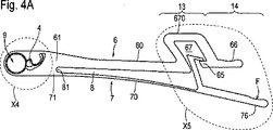
可撓ブランチ7にそのハンドル部分76で前向きの力Fが及ぼされると、この結果、弾性変形が起こり表示器部位13の切り抜き8が広がるが、この広がりは溝底部81に入り狭まる。可撓ブランチ7を撓ませるため、使用者はハンドル部分76を掴み、計量目盛り69、79で所期のトルクが達成されるまで、時計方向に、即ち、ねじ込む前方向(ねじ込み方向)に基部ハンドル66から離れるように前向きの力Fで移動させる。可撓ブランチ7が広がり過ぎないように、第2の分岐部分73は、可撓ブランチ7が最大に撓んだ時、衝止足65に当接し、そのため更に曲がることが阻止される。前鼻部44および隣接する第3の側面43と、対向する溝93および隣接するウェブ94との嵌め合い係合のため、トルクレンチ1を右回しにねじ込むと、ねじ込み器具9が一緒に回転する。ねじ込み動作中に発生する抵抗のため、第2の側面42は爪ばね47の弾性に抗して第1の衝止部50に押し当てられ、そのため、前にまだ存在していた空間が閉鎖される。爪セグメント40の位置は少ししか変化しないため、垂直軸線Vと前鼻部44の間の最小距離a0は原則的に変化しないと仮定することができる。しかし、この点で、図3D(静止状態)と図4B(ねじ込む前方向の負荷)の状態の間には差異がある。
Regarding FIGS. 4A-4C:
When a forward force F is exerted on the
図5A〜図5Cに関して:
空間の状態に応じて、例えば、患者の口の狭い所では、図4Aのトルクレンチ1を、ねじ込む前方向に、可能な弓形の範囲で操作し、その上で更にねじ込む動作が必要な場合、トルクレンチ1を、逆に、反時計回りに(ラチェット器具としての機能において)、戻し方向に軸線Vを中心とした回転運動で戻し方向の力F’により操作しなければならない。
Regarding FIGS. 5A-5C:
Depending on the condition of the space, for example, in a narrow area of the patient's mouth, if the torque wrench 1 of FIG. On the contrary, the torque wrench 1 must be operated counterclockwise (in the function as a ratchet instrument) by a rotational force about the axis V in the return direction with a force F ′ in the return direction.
戻し移動の場合、ねじ込み器具9は、適用されたねじに作用する抵抗のため、その位置に留まる。同時に、爪セグメント40は、爪ばね47の弾性作用に抗して第1の衝止部50から第2の衝止部51に案内され、そのため軸線Vと前鼻部44の間は最大距離a1になる。最大距離a1に達すると、ウェブ94が第1の側面41と前鼻部44を過ぎて移動することが可能になる。これは、トルクレンチ1の戻し移動中、複数のウェブ94の周囲を爪セグメント40が移動できることを意味する。再度前向きの移動に切り換わる時、爪セグメント40を第2の衝止部51の方向に押す力がなくなり、その結果、爪セグメント40は爪ばね47に案内されて第1の衝止部50に戻り、図4Aのねじ込み動作の状態が回復する。
In the case of a return movement, the screwing
図6A〜図6Cに関して:
この一群の図は、第2の態様のトルクレンチ1を示し、トルクレンチ1は、ここでも頭部位10、首部位11、シャンク部位12、表示器部位13、およびハンドル部位14で構成されている。前述の態様との有意な差異は、爪4とそれを取り囲む自由空間5の形状にある。トルクレンチ1の下縁に対して、爪4と自由空間5はここでは凸状に延びており、爪セグメント40はむしろ舌状の形態であり、上部の第1の衝止部50は、より短い基本的にまっすぐの縁で形成されている。頭部位10は、基本的に完全な円形の受入開口部3を取り囲む円形の周囲部2を有し、受入開口部3の中心に軸線Vが平面Hに対して垂直に延びる。第1の衝止部50の反対側に、自由空間5の接続部の底に窪状の第2の衝止部51が変更されずに配置されている。爪ばね47は、ばねの付け根46のところで爪セグメント40から、ばね接続部48まで延び、そこで首部位11に移行する。爪ばね47の両側に第1および第2のばね遊隙52,52’が延び、一方側はそれぞればね接続部48に隣接する底部53で終端し、他方側は爪セグメント40に隣接する受入開口部3に入る。爪セグメント40は、前部が、受入開口部3の中に突出する前鼻部44となって終端し、前鼻部44から上方向に第1の側面41が延び、この第1の側面は第2の側面42に移行し、これはばねの付け根46の方に延びる。前鼻部44は、下方向に、第3の側面43に移行し、これはばねの付け根46の方向に延びる。静止状態では、軸線Vと前鼻部44は最小距離a0だけ離間している。基部ブランチ6および可撓ブランチ7は、首部位11の端部で移行部61、71から、まず縦足60、70として延び、その間に切り抜き8が配置され、この切り抜きは頭部位10の方向で、溝底部81で終端する。ハンドル76は、その上部に、細長い凹部760を有し、その中に基部ハンドル66が受け入れられる。残りの特徴は、基本的に第1の態様のトルクレンチ1に対して変更されておらず、これは計量目盛り69、79にも当てはまる。
Regarding FIGS. 6A-6C:
This group of figures shows a torque wrench 1 according to a second embodiment, which again comprises a
図7に関して:
第2の態様のねじ込み器具9は、ここでも、上面91と下面92を有する頭部90を有し、シャンク96が下面の中心から器具先端97まで延びる。第1の態様のねじ込み器具9と対照的に、溝93’は、この場合、基本的に角ばった断面を有し、その間に配置されているウェブ94’も同様に角ばっており、このため一周ぐるりと蛇行状になっている。
Regarding FIG. 7:
The screwing
図8Aおよび図8Bに関して:
ねじ込み器具9をトルクレンチ1の受入開口部3に挿入すると、頭部90およびシャンク96は軸線Vと整列している。溝93’とウェブ94’を備える輪郭を有する円筒状の頭部90は、周囲部2によって取り囲まれている。静止状態では、ハンドル部分76は操作されておらず、即ち、時計方向に引かれてもなく、戻し方向に移動してもなく、爪4全体が撓んでおらず、このようにして爪ばね47には応力がかかっておらず、2つのばね遊隙52、52’の輪郭は、変化していない。爪セグメント40は、第1および第2の衝止部50、51から短い距離だけ離間しており、最も近い溝93’の中に突出する。軸線Vと前鼻44の間に最小距離a0が存在する。
Regarding FIGS. 8A and 8B:
When the screwing
図9Aおよび図9Bに関して:
この一対の図は、原則的に図4A〜図4Cに対応しており、ねじ込み器具9が挿入され、前方向に移動した、即ち、ハンドル部分76が時計方向に力Fを受け、そのため可撓ブランチ7が実質上最大の程度まで変形している、第2の態様のトルクレンチ1を示す。第1の分岐部分72は、大部分、遊隙67から外に移動しており、衝止部の役割をする第2の分岐部分73は衝止足65の近傍に配置されている。同時に、凹部760は、基部ハンドル66がもはやその中に配置されていないため、完全に空いている。例えば、ねじに係合するねじ込み器具9は、打ち勝たなければならない締付けトルクにより抵抗力を受け、そのため、締付けトルクの大きさに応じて、爪セグメント40は隣接するウェブ94’により第1の衝止部50の方向に撓む。前鼻部44は最大の程度まで溝93’に係合し、その時、前鼻部44と軸線Vとの距離は基本的に変わらず、更に、最小距離a0に等しい。最大に撓んだ場合、爪セグメント40は第1の衝止部50に当接する。爪4が撓んだため、ばね遊隙52、52’間の関係が変化し、この時、第1のばね遊隙52は狭くなり、第2のばね遊隙52’はそれに対応して広くなっている。ハンドル部分76に作用する力Fが締付けトルクに打ち勝つとき、トルクレンチ1は時計方向に移動し、その過程で、中に挿入されているねじ込み器具9を一緒に動かす。
Regarding FIGS. 9A and 9B:
This pair of figures corresponds in principle to FIGS. 4A to 4C, in which the screwing
図10A〜図10Cに関して:
この一群の図は、原則的に図5A〜図5Cに対応しており、ねじ込み器具9が挿入され、戻し方向に移動した、即ち、ハンドル部分76に反時計回りの力F’が作用する、第2の態様のトルクレンチ1を示す。基部ブランチ6および可撓ブランチ7は互いに近傍に配置されており、後者と切り抜き8は変形していない。第1の分岐部分72および第2の分岐部分73は、遊隙67のずっと中に移動している。解除トルクに打ち勝っていないため、ねじ込み器具9は静止状態にあり、そのため、爪セグメント40の次のウェブ94’によって爪4が撓む。その結果、爪セグメント40は、第2の衝止部51の方向に押され、爪セグメント40と軸線Vの間が最大距離a1になり、そのため、爪セグメント40は、ウェブ94’の環状の表面との接触から離れて、ねじ込み器具9の頭部90から係脱する。その時、爪ばね47が曲がり、その結果、第1のばね遊隙52は広がり、同時に第2のばね遊隙52’は狭くなっている。
Regarding FIGS. 10A-10C:
This group of views corresponds in principle to FIGS. 5A to 5C, in which the screwing
図11A〜図12Bに関して:
これらの図は、第3の態様のトルクレンチ1を示す。爪セグメント40と爪ばね47の輪郭を有する爪4全体、並びに、隣接する上部の第1の衝止部50と下部の窪状の第2の衝止部51を有する自由空間5が単に変更されている。爪セグメント40は、この場合、むしろ角ばった舌形をしており、前部が、受入開口部3の中に突出する前鼻部44として終端し、前鼻部44から上向きに第1の側面41が延び、この第1の側面41に第2の側面42が隣接し、これがばねの付け根46と交わる。前鼻部44に下方向に第3の側面43が続き、これは、ばねの付け根46に移行する。自由空間5は、この場合、首部位11内で底部53の方向に、接続部から受入開口部3の中に渦巻き状になっている。爪ばね47は、同様に渦巻き状に自由空間5を通って延び、ここでも自由空間5を第1および第2のばね遊隙52、52’に分割し、ばね接続部48で終端する。第1の衝止部50は比較的急傾斜であり、爪セグメント40は、この時の静止状態では軸線Vから最小距離a0だけ離間している。下部の衝止部51の窪みの輪郭は、比較的はっきりとしている。トルクレンチ1の要素の残りは全て、前述の形態に対して変更されておらず、これは計量目盛り69、79にも当てはまる。
Regarding FIGS. 11A-12B:
These drawings show the torque wrench 1 of the third aspect. The
また、この場合も、第3の態様のトルクレンチ1に第2の態様のねじ込み器具9が挿入される。静止状態では、ハンドル部分76に前向きの力Fも戻し力F’も作用せず、基部ハンドル66は凹部760内に配置されており、前鼻部44は溝93’のずっと中に突出し、爪セグメント40およびそこから突出する爪ばね47を有する爪4全体は、自由空間5内で撓んでいない。爪セグメント40は、2つの衝止部50、51から離間している。
Also in this case, the screwing
図13Aおよび図13Bに関して:
第2の態様のねじ込み器具9が挿入されている第3の態様のトルクレンチ1を前方向に操作する時、撓んだハンドル部分76に前向きの力Fが作用し、状態は、図4A〜図4C、並びに図9Aおよび図9Bのものに類似である。爪4の位置、および、爪4とねじ込み器具9との相互作用だけが、爪4、自由空間5および隣接する輪郭の変更のために異なっている。ねじ込み器具9が受ける抵抗によって、前鼻部44が溝93’の中にある爪セグメント40は第1の衝止部50に押し当てられ、爪ばね47も撓み、このようにして2つのばね遊隙52、52’の関係が変わる。前鼻部44と軸線Vとの最小距離a0は原則的に維持される。
Regarding FIGS. 13A and 13B:
When the torque wrench 1 of the third mode in which the screwing
図14A〜図14Cに関して:
この一群の図は、戻し方向に操作する時の、即ち、ハンドル部分76に戻し力F’が作用する時の、第2の態様のねじ込み器具9が挿入されている第3の態様のトルクレンチ1を示す。ねじ込み器具9は拘束された位置にあるため、爪セグメント40の前鼻部44は、前に入っていた溝93’から出てウェブ94’の環状の表面まで移動し、爪4全体が撓み、爪セグメント40は第2の衝止部51の方向に移動する。前鼻部44は、軸線Vから最大距離a1まで移動し、第2のばね遊隙52’は、特に第2の衝止部51の部位で狭くなり、同時に第1の遊隙52は、特に第1の衝止部50の部位で広くなる。
Regarding FIGS. 14A-14C:
This group of figures shows a torque wrench of the third mode in which the screwing
Claims (12)
a)それぞれの部位が平面(H)内で延びる、最前部に配置されている頭部位(10)、隣接する首部位(11)、それに続くシャンク部位(12)、および最後部に配置されているハンドル部位(14)、
b)前記頭部位(10)に設けられている受入開口部(3)であって、この受入開口部が、
ba)周囲部(2)によって取り囲まれており、
bb)その中心点を通って、軸線(V)が垂直に通って延びる該中心点を有し、および、
bc)平面(H)に垂直な前記軸線(V)の延長に沿ってねじ込み器具(9)を挿入する役割をする、
該受入開口部(3)、
c)前記受入開口部(3)の周縁に配置され、制限された範囲で移動が可能な爪セグメント(40)であって、この爪セグメントの前部分(41〜44)が前記受入開口部(3)の方を向いており、その際、前記前部分(41〜44)が、
ca)トルクレンチ(1)をねじ込み方向に操作する時、前記ねじ込み器具(9)の頭部(90)に設けられている外側輪郭(93、94;93’、94’)と、一緒に動くように係合すること、および、
cb)トルクレンチ(1)を戻し方向に操作する時、前記ねじ込み器具(9)の頭部(90)に設けられている前記外側輪郭(93、94;93’、94’)と、一緒に動くような係合を解除すること、
が意図されている、
該爪セグメント(40)、および、
d)前記首部位(11)から前記トルクレンチ(1)に沿って延びる曲げ剛性のある基部ブランチ(6)、
を有する前記トルクレンチ(1)において、
e)撓むことができる、弾性の可撓ブランチ(7)が設けられており、前記トルクレンチ(1)をねじ込み方向に操作する時、使用者が及ぼす前向きの力(F)により、前記可撓ブランチ(7)を介して、発生し得るトルクが掛けられること、
f)爪ばね(47)が前記爪セグメント(40)から前記首部位(11)に延び、その際、前記爪セグメント(40)と前記爪ばね(47)が、一体型の爪(4)又は複数の部品から構成される爪(4)を形成すること、
g)前記爪セグメント(40)および前記爪ばね(47)がチャネル状の自由空間(5)内に配置されており、前記自由空間が、前記爪ばね(47)の力に抗しての平面(H)内での、前記両方の爪セグメントと爪ばねの撓みを許容すること、および、
h)前記爪(4)が前記首部位(11)から一体に形成されているか、又は別々の部品として前記首部位(11)に固定されていること、
を特徴とするトルクレンチ(1)。A torque wrench (1) as a ratchet device for the medical field,
a) Each part extends in the plane (H), the head part (10) arranged in the foremost part, the adjacent neck part (11), the subsequent shank part (12), and the last part The handle part (14),
b) a receiving opening (3) provided in the head region (10), wherein the receiving opening is
ba) surrounded by the perimeter (2),
bb) having its center point extending through its center point, the axis (V) extending vertically , and
bc) serves to insert the screwing device (9) along an extension of the axis (V) perpendicular to the plane (H);
The receiving opening (3),
c) A claw segment (40) which is disposed on the periphery of the receiving opening (3) and is movable within a limited range, and the front portions (41 to 44) of the claw segment are connected to the receiving opening ( 3), in which case the front part (41-44)
ca) When operating the torque wrench (1) in the screwing direction, it moves together with the outer contour (93, 94; 93 ′, 94 ′) provided on the head (90) of the screwing device (9). Engaging, and
cb) When operating the torque wrench (1) in the return direction , together with the outer contour (93, 94; 93 ′, 94 ′) provided on the head (90) of the screwing device (9) Releasing the moving engagement,
Is intended,
The nail segment (40), and
d) a bending rigid base branch (6) extending from the neck portion (11) along the torque wrench (1);
In the torque wrench (1) having:
e) An elastic flexible branch (7) that can be bent is provided, and when the torque wrench (1) is operated in the screwing direction , the forward force (F) exerted by the user exerts the allowable branch. A torque that can be generated is applied via the flexible branch (7);
f) A claw spring (47) extends from the claw segment (40) to the neck portion (11), where the claw segment (40) and the claw spring (47) are integrated into the claw (4) or Forming a nail (4) composed of a plurality of parts;
g) The claw segment (40) and the claw spring (47) are disposed in a channel-shaped free space (5), and the free space is a flat surface against the force of the claw spring (47). Allowing deflection of both said claw segments and claw springs within (H); and
h) the claw (4) is integrally formed from the neck part (11) or is fixed to the neck part (11) as a separate part;
A torque wrench (1) characterized by
b)自由空間(5)が第1および第2の衝止部(50、51)で受入開口部(3)に開放していること、
c)前記第1の衝止部(50)が前記第2の側面(42)の反対側に配置されており、前記トルクレンチ(1)をねじ込み方向に操作した時、撓んでいない爪(4)の前記第2の側面(42)が前記第1の衝止部(50)に当接し、前記前鼻部(44)が前記軸線(V)から最小距離(a0)だけ離間していること、および、
d)前記第2の衝止部(51)が少なくとも一部、前記第3の側面(43)の反対側に配置されており、前記トルクレンチ(1)を戻し方向に操作した時、撓んだ前記爪(4)の前記第3の側面(43)が前記第2の衝止部(51)の方に移動しているか又はそれに当接し、ここで、前記前鼻部(44)は前記軸線(V)から最大距離(a1)だけ離間し、前記第2の側面(42)は前記第1の衝止部(50)から離れ、前記爪ばね(47)が、前記爪ばねの復元力に抗して弾性変形していること、
を特徴とする、請求項1に記載のトルクレンチ(1)。a) The claw segment (40) has a front nose (44) at the front part (41-44) of the claw segment, and a second side surface (42) is arranged on one side of the front nose. The third side (43) is arranged on the other side,
b) the free space (5) is open to the receiving opening (3) at the first and second stop (50, 51);
c) The first stop (50) is disposed on the opposite side of the second side surface (42), and the nail (4) is not bent when the torque wrench (1) is operated in the screwing direction. ) Is in contact with the first stop (50), and the front nose (44) is separated from the axis (V) by a minimum distance (a 0 ). And
d) The second stop portion (51) is at least partially disposed on the opposite side of the third side surface (43), and is bent when the torque wrench (1) is operated in the return direction. The third side (43) of the claw (4) is moving toward or abutting the second stop (51), where the front nose (44) A distance from the axis (V) is the maximum distance (a 1 ), the second side surface (42) is separated from the first stop (50), and the claw spring (47) is restored to the claw spring. Be elastically deformed against force,
The torque wrench (1) according to claim 1, characterized by:
aa)一方側では、ばねの付け根(46)のところで前記爪セグメント(40)に移行し、他方側では、ばね接続部(48)のところで前記首部位(11)に移行し、且つ、
ab)直線的な又は少なくとも一部湾曲した板ばねの形態であること、
b)前記爪セグメント(40)の前記前鼻部(44)に、
ba)一方向で、第1の側面(41)が続き、前記第1の側面に第2の側面(42)が隣接し、
bb)他方向で、第3の側面(43)が続き、前記第3の側面(43)が前記ばねの付け根(46)の方向に丸く延び、
bc)前記前鼻部(44)が前記受入開口部(3)の方向に盛り上がった先端又は凸部として形成されており、
c)前記第1の衝止部(50)がまっすぐな縁として形成されており、前記第2の衝止部(51)が窪状の形態を有し、
d)前記自由空間(5)を通って突出する前記爪ばね(47)が、第1および第2のばね遊隙(52、52’)を分割し、前記遊隙の割合は前記爪ばね(47)が移動する時変化し、
前記爪ばね(47)が底部(53)で終端し、前記底部(53)に前記ばね接続部(48)が続くこと、
を特徴とする、請求項1または2に記載のトルクレンチ(1)。a) The claw spring (47)
aa) on one side transitions to the claw segment (40) at the base of the spring (46), on the other side transitions to the neck part (11) at the spring connection (48), and
ab) in the form of a straight or at least partially curved leaf spring;
b) on the front nose (44) of the nail segment (40);
ba) In one direction, the first side (41) continues, the second side (42) is adjacent to the first side,
bb) in the other direction , followed by a third side surface (43), said third side surface (43) extending in the direction of the base of the spring (46),
bc) The front nose portion (44) is formed as a tip or convex portion raised in the direction of the receiving opening (3),
c) the first stop (50) is formed as a straight edge, and the second stop (51) has a concave shape;
d) The claw spring (47) protruding through the free space (5) divides the first and second spring gaps (52, 52 ′), the proportion of the gap being the claw springs ( 47) changes when moving,
The claw spring (47) terminates at the bottom (53) and the bottom (53) is followed by the spring connection (48);
Torque wrench (1) according to claim 1 or 2, characterized in that
b)前記可撓ブランチ(7)が、まず細長い縦足(70)として且つ前記縦足(60)に平行に、前記首部位(11)に配置されている移行部(71)から表示器部位(13)に延び、前記ハンドル部位(14)でハンドル部分(76)として自由端を有し、前記ハンドル部分(76)が前記基部ハンドル(66)を越えて突出すること、
c)可撓ブランチ(7)が、この可撓ブランチの上面に、基部ブランチ(6)の方を向いている凹部(760)を有していることが可能であり、前記凹部の中において、前記衝止足(65)と前記基部ハンドル(66)が一部、嵌め込まれること、および、
d)前記基部ブランチ(6)の縦足(60)と前記可撓ブランチ(7)の縦足(70)との間に切り抜き(8)が配置されており、前記切り抜きが移行部(61、71)に隣接する溝底部(81)から前記表示器部位(13)に延びること、
を特徴とする、請求項1〜3のいずれか一つに記載のトルクレンチ(1)。a) The base branch (6), first as a longitudinal leg (60), goes from the transition part (61) arranged in the neck part (11) through the shank part (12) to the display part (13). Having a free end as a base handle (66) at the handle portion (14),
b) The flexible branch (7) is first shown as an elongated longitudinal leg (70) and parallel to the longitudinal leg (60), from the transition part (71) arranged in the neck part (11) to the indicator part. Extending to (13), having a free end as a handle portion (76) at said handle portion (14), said handle portion (76) projecting beyond said base handle (66);
c) The flexible branch (7) can have a recess (760) on the top surface of the flexible branch facing the base branch (6), The pawl (65) and the base handle (66) are partially fitted, and
d) a cutout (8) is arranged between the longitudinal leg (60) of the base branch (6) and the longitudinal leg (70) of the flexible branch (7), the cutout being a transition part (61, 71) extending from the groove bottom (81) adjacent to the indicator part (13);
Torque wrench (1) according to any one of claims 1 to 3, characterized in that
aa)前記縦足(60)と前記基部ハンドル(66)との間に配置されている、前記基部ブランチ(6)の少なくとも1つの分岐部分(62、63、64)、および、
ab)前記可撓ブランチの縦足(70)と前記ハンドル部分(76)との間に配置されている、前記可撓ブランチ(7)の少なくとも1つの分岐部分(72、73)、
で形成されていること、および、
b)前記トルクレンチ(1)がねじ込み方向に操作され、前記可撓ブランチ(7)が撓む時、前記基部ブランチ(6)の前記少なくとも1つの分岐部分(62、63、64)と前記可撓ブランチ(7)の前記少なくとも1つの分岐部分(72、73)との間の相対的位置が、ゼロ位置を有する静止状態を出発点として、発生したトルクの尺度である増分変化を経るように構成されていること、
を特徴とする、請求項1〜4のいずれか一つに記載のトルクレンチ(1)。a) The indicator part (13)
aa) at least one bifurcation (62, 63, 64) of the base branch (6) disposed between the longitudinal leg (60) and the base handle (66); and
ab) at least one branch portion (72, 73) of the flexible branch (7), disposed between the longitudinal leg (70) of the flexible branch and the handle portion (76);
Is formed of, and
b) When the torque wrench (1) is operated in the screwing direction and the flexible branch (7) is bent, the at least one branch part (62, 63, 64) of the base branch (6) and the possible The relative position between the at least one branch portion (72, 73) of the flexible branch (7) undergoes an incremental change, which is a measure of the torque generated, starting from a stationary state having a zero position. That it is configured,
Torque wrench (1) according to any one of claims 1 to 4, characterized in that
a)前記少なくとも1つの分岐部分(62、63、64)によって形成され、遊隙(67)を取り囲み、前記遊隙(67)に通路(68)が設けられており、前記縦足(60)から前記基部ハンドル(66)まで延びる、ブラケット(670)、および、
b)前記通路(68)を通って前記遊隙(67)の中に突出する、前記可撓ブランチ(7)の前記少なくとも1つの分岐部分(72、73)、
を備えることを特徴とする、請求項1〜6のいずれか一つに記載のトルクレンチ(1)。The indicator part (13) is
a) formed by the at least one branch portion (62, 63, 64), surrounding the play (67), and having a passage (68) in the play (67), the longitudinal foot (60) Extending from the base handle (66) to the bracket (670), and
b) the at least one branch portion (72, 73) of the flexible branch (7) protruding into the play (67) through the passage (68);
The torque wrench (1) according to any one of claims 1 to 6, characterized by comprising:
前記縦足(60)からL形に曲がる第1の基部分岐部分(62)、および、
前記第1の基部分岐部分に連続して隣接する第2の基部分岐部分(63)、および、前記基部ハンドル(66)にL形に移行する第3の基部分岐部分(64)、
から構成されていること、
b)第1の分岐部分(72)に第2の分岐部分(73)がL形に隣接すること、
c)衝止足(65)が前記基部ハンドル(66)から内向きに、前記縦足(60)の方向に延び、一方側で通路(68)を画定し、ここで、
d)前記遊隙(67)、前記衝止足(65)および前記通路(68)は、いわば固定要素として、
前記第1の分岐部分(72)と第2の分岐部分(73)は、可撓ブランチ(7)によって撓むことができる要素として、
前記可撓ブランチ(7)の最大の撓みが前記第2の分岐部分(73)の前記衝止足(65)上への載置によって決まるように寸法を設定されていること、
を特徴とする、請求項1〜7のいずれか一つに記載のトルクレンチ(1)。a) The bracket (670) is serpentine,
A first base branch (62) that bends in an L-shape from the longitudinal leg (60); and
A second base branch portion (63) that is continuously adjacent to the first base branch portion, and a third base branch portion (64) that transitions to an L shape to the base handle (66),
Consists of
b) the second branch portion (73) is adjacent to the first branch portion (72) in an L-shape;
c) A pawl (65) extends inwardly from the base handle (66) in the direction of the longitudinal foot (60) and defines a passageway (68) on one side, wherein
d) The play (67), the pawl (65) and the passage (68) are, to say, fixing elements,
The first branch portion (72) and the second branch portion (73) are elements that can be bent by the flexible branch (7).
Dimensioned such that the maximum deflection of the flexible branch (7) is determined by the placement of the second branch portion (73) on the stop foot (65);
Torque wrench (1) according to any one of the preceding claims, characterized in that
ab)前記第2の計量目盛り(79)が、基準線又は矢印としての表示要素の形態で、前記可撓ブランチ(7)の前記第1又は第2の分岐部分(72、73)に設けられていること、又は、
ba)前記第1の計量目盛り(69)が、基準線又は矢印としての表示器要素の形態で、前記基部ブランチ(6)の衝止足(65)に、前記可撓ブランチ(7)の第1の分岐部分(72)の方向に設けられていること、および、
bb)前記第2の計量目盛り(79)が、0Ncm〜40Ncmの範囲を有する計量目盛りの形態で、前記第1の分岐部分(72)に設けられていること、
を特徴とする、請求項1〜8のいずれか一つに記載のトルクレンチ(1)。aa) the first weighing scale (69) is provided on at least one of the base branch parts (62, 64) in the form of a weighing scale having a range of 0 Ncm to 40 Ncm ; and
ab) The second weighing scale (79) is provided in the first or second branch part (72, 73) of the flexible branch (7) in the form of a display element as a reference line or an arrow. to have it, or,
ba) The first weighing scale (69) is in the form of a display element as a reference line or an arrow, on the stop leg (65) of the base branch (6), the second of the flexible branch (7). Being provided in the direction of one branch portion (72), and
bb) the second weighing scale (79) is provided on the first branch part (72) in the form of a weighing scale having a range of 0 Ncm to 40 Ncm ;
Torque wrench (1) according to any one of the preceding claims, characterized in that
a)一体に製造されていること、又は、
b)前記爪(4)が別々の構成部品として前記トルクレンチ(1)に固定されていること、
を特徴とする、請求項1〜9のいずれか一つに記載のトルクレンチ(1)。It has a head part (10), a neck part (11), a nail (4), a shank part (12), a display part (13), a handle part (14), a base branch (6) and a flexible branch (7). The entire torque wrench (1)
a) it is manufactured in one piece, or
b) the claw (4) being fixed to the torque wrench (1) as a separate component;
Torque wrench (1) according to any one of the preceding claims, characterized in that
a)少なくとも特殊鋼、チタン、セラミック材料およびプラスチックを含む群の材料から製造されること、および、
b)少なくともレーザー切削およびウォータージェット切削、ワイヤカットEDM、フライス加工、打抜き加工、射出成形、又は金属ダイカストを含む群の方法で製造されること、
を特徴とする、請求項1〜10のいずれか一つに記載のトルクレンチ(1)。The torque wrench (1)
a) manufactured from the group of materials including at least special steel, titanium, ceramic materials and plastics, and
b) Manufactured by a group of methods including at least laser and water jet cutting, wire cut EDM, milling, stamping, injection molding, or metal die casting,
Torque wrench (1) according to any one of the preceding claims, characterized in that
Applications Claiming Priority (3)
| Application Number | Priority Date | Filing Date | Title |
|---|---|---|---|
| DE202004014195U DE202004014195U1 (en) | 2004-09-13 | 2004-09-13 | Torque wrench as ratchet instrument for medical technology |
| DE202004014195.7 | 2004-09-13 | ||
| PCT/CH2005/000177 WO2006029542A1 (en) | 2004-09-13 | 2005-03-26 | Torque key as a ratchet instrument in the medical field |
Publications (3)
| Publication Number | Publication Date |
|---|---|
| JP2008512254A JP2008512254A (en) | 2008-04-24 |
| JP2008512254A5 JP2008512254A5 (en) | 2011-06-30 |
| JP4801073B2 true JP4801073B2 (en) | 2011-10-26 |
Family
ID=33483571
Family Applications (1)
| Application Number | Title | Priority Date | Filing Date |
|---|---|---|---|
| JP2007530563A Active JP4801073B2 (en) | 2004-09-13 | 2005-03-26 | Torque wrench as a ratchet device for the medical field |
Country Status (7)
| Country | Link |
|---|---|
| US (1) | US7597032B2 (en) |
| EP (1) | EP1796563B1 (en) |
| JP (1) | JP4801073B2 (en) |
| KR (1) | KR101184241B1 (en) |
| DE (1) | DE202004014195U1 (en) |
| ES (1) | ES2436093T3 (en) |
| WO (1) | WO2006029542A1 (en) |
Families Citing this family (35)
| Publication number | Priority date | Publication date | Assignee | Title |
|---|---|---|---|---|
| US20070009851A1 (en) * | 2005-07-07 | 2007-01-11 | Kerrhawe Sa | Dental instrument with movable tip portion |
| CN101790438B (en) * | 2007-06-01 | 2012-11-07 | 医乐世品诺有限公司 | Torque wrench, handle and head piece |
| DE102008046989A1 (en) * | 2007-09-14 | 2009-05-20 | Martin Teichmann | Screwing tool, particularly for use in medical technology, has ratchet head and actuating grip where ratchet head has receiving opening for insertion of screwing-in tool |
| KR100834209B1 (en) * | 2007-12-26 | 2008-05-30 | 최길운 | The medical torque wrench |
| ATE482669T1 (en) * | 2008-03-11 | 2010-10-15 | Hader Sa | DYNAMOMETRIC INSTRUMENT WITH REMOVABLE HEAD |
| US20090305191A1 (en) * | 2008-06-04 | 2009-12-10 | Global Implant Solutions, Llc | Failsafe Installation Tool For Dental Implants |
| ES2381717B1 (en) | 2008-11-14 | 2013-04-26 | Biotechnology Institute, I Mas D, S.L. | WRENCH TO DELIVER A MAXIMUM FIXED OR ADJUSTABLE TORQUE |
| US20100233653A1 (en) * | 2009-03-11 | 2010-09-16 | Cheng-Kang Yeh | Wrench for dental implant |
| WO2011016305A1 (en) * | 2009-08-05 | 2011-02-10 | オリンパスメディカルシステムズ株式会社 | Torque wrench and ultrasonic surgery device |
| GB2511451B (en) * | 2010-12-22 | 2015-06-17 | Thomas William Lawrie-Fussey | Fastening device and tightening tool |
| DE102011052442B3 (en) * | 2011-08-05 | 2012-09-27 | Hipp Medical Ag | Ratchet and method for transmitting a torque to a counterpart, and use of such a ratchet in the medical field |
| DE102012101050B3 (en) * | 2012-02-09 | 2013-01-17 | Hipp Medical Ag | Ratchet and its manufacturing method and torque transmission system and method for transmitting a torque to a screwing tool, and use of such a ratchet in the medical field |
| TWI455796B (en) * | 2012-10-03 | 2014-10-11 | Poul Chang Metal Industry Co Ltd | Extensionhandle for wrench |
| US9693814B2 (en) | 2013-03-14 | 2017-07-04 | DePuy Synthes Products, Inc. | Torque limiting instrument, system and related methods |
| US9775654B2 (en) * | 2013-03-15 | 2017-10-03 | Aesculap Implant Systems, Llc | Surgical ratchet tool, system and method |
| JP6378580B2 (en) * | 2014-08-22 | 2018-08-22 | 株式会社アルプスツール | Torque spanner |
| WO2016142403A1 (en) * | 2015-03-09 | 2016-09-15 | Straumann Holding Ag | Torque limiting dental tool holder |
| TWI595864B (en) * | 2016-04-22 | 2017-08-21 | 合鎰技研股份有限公司 | Torque adjustable dental implant wrench |
| CN107303202B (en) * | 2016-04-22 | 2019-11-05 | 合镒技研股份有限公司 | The plant tooth spanner of torque-adjustable |
| USD812225S1 (en) * | 2016-05-23 | 2018-03-06 | Titan Dental Systems, LLC | Dental wrench |
| US20170334046A1 (en) * | 2016-05-23 | 2017-11-23 | Titan Dental Systems, LLC | Torque-limiting and ratchetting mechanism |
| DE102017000222B4 (en) | 2017-01-13 | 2019-08-29 | KLINGEL medical metal GmbH | Torque wrenches, in particular torque wrenches for dental applications |
| TWI598194B (en) * | 2017-02-20 | 2017-09-11 | Hou-Fei Hu | Torque indicating wrench |
| EP3375403A1 (en) | 2017-03-15 | 2018-09-19 | Ruetschi Technology AG | A medical instrument for holding and torque control tightening a threaded implant device and packaging of the same |
| EP3527328A1 (en) | 2018-02-14 | 2019-08-21 | Ruetschi Technology AG | A disposable instrument for torque control tightening a threaded implant device |
| CN208697287U (en) | 2018-07-25 | 2019-04-05 | 北京水木天蓬医疗技术有限公司 | The torque spanner of ultrasound knife |
| WO2020127331A1 (en) | 2018-12-19 | 2020-06-25 | Straumann Holding Ag | Dental torque wrench |
| WO2020182973A1 (en) | 2019-03-13 | 2020-09-17 | Straumann Holding Ag | Dental torque wrench |
| JP1668785S (en) * | 2019-06-13 | 2020-09-23 | ||
| JP1666452S (en) * | 2019-08-03 | 2020-08-24 | ||
| US10828134B1 (en) * | 2019-11-28 | 2020-11-10 | Amirhossein Majidi | Dental implant prosthetic and surgical life-saving kit |
| DE102019134654A1 (en) * | 2019-12-17 | 2021-06-17 | Dormakaba Deutschland Gmbh | Torque indicator |
| TWI742925B (en) * | 2020-11-16 | 2021-10-11 | 財團法人金屬工業研究發展中心 | Tool for bone implant |
| US11628005B2 (en) * | 2020-12-03 | 2023-04-18 | Metal Industries Research & Development Centre | Tool for bone implant |
| WO2023166407A1 (en) * | 2022-03-02 | 2023-09-07 | Bosonic Ag | Wrench with torque indicator |
Citations (2)
| Publication number | Priority date | Publication date | Assignee | Title |
|---|---|---|---|---|
| JPH08182691A (en) * | 1994-09-27 | 1996-07-16 | Inst Straumann Ag | Torque wrench for surgery with torque indicator |
| US6109150A (en) * | 1999-08-06 | 2000-08-29 | Saccomanno, Iii; Matthew | Torque indicating wrench |
Family Cites Families (15)
| Publication number | Priority date | Publication date | Assignee | Title |
|---|---|---|---|---|
| CH91638A (en) * | 1921-02-06 | 1921-11-01 | E Boesch | Key ratchet. |
| US2447109A (en) | 1945-11-07 | 1948-08-17 | Ammco Tools Inc | Torque measuring wrench |
| US2936661A (en) * | 1957-12-26 | 1960-05-17 | Hughes Aircraft Co | Torque limiting wrench |
| GB1104501A (en) * | 1964-10-15 | 1968-02-28 | Mini Of Technology | Improvements in pawl and ratchet type hand tools |
| FR1498385A (en) * | 1966-06-17 | 1967-10-20 | Hand torque wrench | |
| US3587307A (en) | 1969-12-05 | 1971-06-28 | Allen E Newberg | Torque wrench adapter |
| DE9402607U1 (en) * | 1994-02-17 | 1994-04-14 | Schwartz Werner Dipl Ing | Ratchet for screw connections in the dental field |
| US5709137A (en) * | 1995-04-24 | 1998-01-20 | Blacklock; Gordon D. | Torque clutched reversible ratchet wrench |
| US5996453A (en) * | 1995-04-24 | 1999-12-07 | Hand Tool Design Corporation | Ratchet mechanism which resists spontaneous disengagement for use in wrenches and other tools |
| US5653151A (en) * | 1995-04-24 | 1997-08-05 | Blacklock; Gordon D. | Reversible ratchet driving tool |
| US5597305A (en) | 1995-06-12 | 1997-01-28 | Ray, Sr.; Charles M. | Dental wrench |
| US6382051B1 (en) | 2001-09-05 | 2002-05-07 | Chih-Min Chang | Ratchet wrench |
| US6988430B1 (en) * | 2002-01-16 | 2006-01-24 | Snap-On Incorporated | Wrench with flexible ring |
| US6862955B1 (en) * | 2004-01-16 | 2005-03-08 | A. A. G. Industrial Co. Ltd. | Wrench having a ratchet wheel |
| US20060027049A1 (en) * | 2004-08-09 | 2006-02-09 | Arnold Robert L | Ratcheting wrench |
-
2004
- 2004-09-13 DE DE202004014195U patent/DE202004014195U1/en not_active Expired - Lifetime
-
2005
- 2005-03-26 WO PCT/CH2005/000177 patent/WO2006029542A1/en active Application Filing
- 2005-03-26 ES ES05714719T patent/ES2436093T3/en active Active
- 2005-03-26 EP EP05714719.1A patent/EP1796563B1/en active Active
- 2005-03-26 JP JP2007530563A patent/JP4801073B2/en active Active
- 2005-03-26 KR KR1020077008141A patent/KR101184241B1/en active IP Right Grant
- 2005-03-26 US US11/662,390 patent/US7597032B2/en active Active
Patent Citations (2)
| Publication number | Priority date | Publication date | Assignee | Title |
|---|---|---|---|---|
| JPH08182691A (en) * | 1994-09-27 | 1996-07-16 | Inst Straumann Ag | Torque wrench for surgery with torque indicator |
| US6109150A (en) * | 1999-08-06 | 2000-08-29 | Saccomanno, Iii; Matthew | Torque indicating wrench |
Also Published As
| Publication number | Publication date |
|---|---|
| ES2436093T3 (en) | 2013-12-27 |
| KR20070072870A (en) | 2007-07-06 |
| WO2006029542A1 (en) | 2006-03-23 |
| US7597032B2 (en) | 2009-10-06 |
| US20080070190A1 (en) | 2008-03-20 |
| EP1796563B1 (en) | 2013-08-28 |
| DE202004014195U1 (en) | 2004-11-18 |
| JP2008512254A (en) | 2008-04-24 |
| KR101184241B1 (en) | 2012-09-21 |
| EP1796563A1 (en) | 2007-06-20 |
Similar Documents
| Publication | Publication Date | Title |
|---|---|---|
| JP4801073B2 (en) | Torque wrench as a ratchet device for the medical field | |
| JP2008512254A5 (en) | ||
| JP5884230B2 (en) | Screw with binding force maintainer | |
| US6109150A (en) | Torque indicating wrench | |
| US6783361B2 (en) | Orthodontic mechanical force module | |
| KR102492424B1 (en) | Surgical screwdrivers and screws | |
| US10864063B2 (en) | Dental implant replica | |
| CN109561946A (en) | Correction shape memory strip | |
| EP1419746A3 (en) | Dental implant system | |
| JP2019514659A (en) | Device for correcting dentition irregularities and method of manufacturing the device | |
| JP2013132553A (en) | Connecting screw for dental implant | |
| WO2005089668A1 (en) | Orthodontic base | |
| US5571014A (en) | Disposable torque limiting wrench | |
| ITMI20101788A1 (en) | QUICK PALAT EXPANDER WITH ANTI-RETURN TOOTH | |
| EP1733698A2 (en) | Abutment for dental implant | |
| WO2011105685A2 (en) | Abutment screw for a dental implant | |
| EP2114289B1 (en) | Dental transfer for fixing the position of endosseous implants in dental arches | |
| JP2002125988A (en) | Plug connection for jaw stamp model | |
| JP6589616B2 (en) | Maxilla enlargement device | |
| EP2943143B1 (en) | Annular resilient retention member | |
| EP2311402A1 (en) | A pressing force stabilizing quickly palate expanding device | |
| KR20110128934A (en) | Apparatus for fastening a dental prosthesis | |
| ITMI20050259U1 (en) | UNBEATABLE TOOL FOR DENTAL CARE WITH PERFECT FIT | |
| US20220031432A1 (en) | Dental torque wrench | |
| JP7323951B2 (en) | expansion screw |
Legal Events
| Date | Code | Title | Description |
|---|---|---|---|
| A621 | Written request for application examination |
Free format text: JAPANESE INTERMEDIATE CODE: A621 Effective date: 20080325 |
|
| RD04 | Notification of resignation of power of attorney |
Free format text: JAPANESE INTERMEDIATE CODE: A7424 Effective date: 20100528 |
|
| A131 | Notification of reasons for refusal |
Free format text: JAPANESE INTERMEDIATE CODE: A131 Effective date: 20110222 |
|
| A524 | Written submission of copy of amendment under article 19 pct |
Free format text: JAPANESE INTERMEDIATE CODE: A524 Effective date: 20110506 |
|
| TRDD | Decision of grant or rejection written | ||
| A01 | Written decision to grant a patent or to grant a registration (utility model) |
Free format text: JAPANESE INTERMEDIATE CODE: A01 Effective date: 20110726 |
|
| A01 | Written decision to grant a patent or to grant a registration (utility model) |
Free format text: JAPANESE INTERMEDIATE CODE: A01 |
|
| A61 | First payment of annual fees (during grant procedure) |
Free format text: JAPANESE INTERMEDIATE CODE: A61 Effective date: 20110804 |
|
| FPAY | Renewal fee payment (event date is renewal date of database) |
Free format text: PAYMENT UNTIL: 20140812 Year of fee payment: 3 |
|
| R150 | Certificate of patent or registration of utility model |
Ref document number: 4801073 Country of ref document: JP Free format text: JAPANESE INTERMEDIATE CODE: R150 Free format text: JAPANESE INTERMEDIATE CODE: R150 |
|
| R250 | Receipt of annual fees |
Free format text: JAPANESE INTERMEDIATE CODE: R250 |
|
| R250 | Receipt of annual fees |
Free format text: JAPANESE INTERMEDIATE CODE: R250 |
|
| R250 | Receipt of annual fees |
Free format text: JAPANESE INTERMEDIATE CODE: R250 |
|
| R250 | Receipt of annual fees |
Free format text: JAPANESE INTERMEDIATE CODE: R250 |
|
| R250 | Receipt of annual fees |
Free format text: JAPANESE INTERMEDIATE CODE: R250 |
|
| R250 | Receipt of annual fees |
Free format text: JAPANESE INTERMEDIATE CODE: R250 |
|
| R250 | Receipt of annual fees |
Free format text: JAPANESE INTERMEDIATE CODE: R250 |
|
| R250 | Receipt of annual fees |
Free format text: JAPANESE INTERMEDIATE CODE: R250 |
|
| R250 | Receipt of annual fees |
Free format text: JAPANESE INTERMEDIATE CODE: R250 |
|
| R250 | Receipt of annual fees |
Free format text: JAPANESE INTERMEDIATE CODE: R250 |