JP4800351B2 - Vehicle occupant protection system - Google Patents
Vehicle occupant protection system Download PDFInfo
- Publication number
- JP4800351B2 JP4800351B2 JP2008192215A JP2008192215A JP4800351B2 JP 4800351 B2 JP4800351 B2 JP 4800351B2 JP 2008192215 A JP2008192215 A JP 2008192215A JP 2008192215 A JP2008192215 A JP 2008192215A JP 4800351 B2 JP4800351 B2 JP 4800351B2
- Authority
- JP
- Japan
- Prior art keywords
- acceleration
- occupant protection
- value
- vehicle
- reference value
- Prior art date
- Legal status (The legal status is an assumption and is not a legal conclusion. Google has not performed a legal analysis and makes no representation as to the accuracy of the status listed.)
- Expired - Lifetime
Links
Images


Description
この発明は、車両衝突時に乗員を保護する乗員保護装置の駆動制御装置に関し、特に車両衝突時の衝撃力の大小に応じて乗員保護装置を駆動させるか否かを判定し、その判定結果に基づいて乗員保護装置の駆動を制御する車両乗員保護装置の駆動判定制御装置に関するものである。 The present invention relates to a drive control device for an occupant protection device that protects an occupant during a vehicle collision, and in particular, determines whether to drive the occupant protection device according to the magnitude of impact force during a vehicle collision, and based on the determination result. The present invention relates to a drive determination control device for a vehicle occupant protection device that controls driving of the occupant protection device.
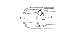
図17は従来の乗員保護システムを備えた車両(自動車)の前部を示す平面図である。同図において、1は車両、2はその車両の座席前方に搭載された乗員保護装置としてのエアバッグ、3はそのエアバッグ2を展開させるための乗員保護制御手段であり、この乗員保護制御手段3は、車両1の衝突時の衝撃を検出するための加速度センサと、この加速度センサから加速度検出信号をデジタルデータとして入力するマイクロコンピュータとを備えた構成となっている。
FIG. 17 is a plan view showing a front portion of a vehicle (automobile) equipped with a conventional occupant protection system. In the figure, 1 is a vehicle, 2 is an airbag as an occupant protection device mounted in front of the seat of the vehicle, 3 is an occupant protection control means for deploying the
次に動作について説明する。
車両1が前方衝突による衝撃を受けると、乗員保護制御手段3の内部に設置された加速度センサが前記衝撃による加速度を検出し、その加速度検出信号をマイクロコンピュータに出力する。マイクロコンピュータは、前記加速度センサから入力した加速度検出信号に基づく演算を行ってエアバッグ2を展開すべきか否かを判定する。この際、エアバッグ2を展開すべきか否かの判定にあたっては、車両の減速度が重要となる。その減速度は、乗員保護制御手段3が加速度センサから入力信号による衝撃加速度検出値を時間積分することで算出されるが、実用上は、前記入力信号へのノイズ等によるオフセット成分が重畳するため、そのオフセット成分によって車両の通常走行時においても衝撃加速度の積算値が累積することとなる。
Next, the operation will be described.
When the
従来の車両用乗員保護システムは以上のように構成されているので、車両の通常走行時における衝撃加速度の積算値が累積されないように、一定条件の下で前記積算値をリセットする対策が施されているが、この場合、そのリセットをかけるタイミング条件の選定が難しく、リセットのための処理手段を追加しなければならないという課題があった。 Since the conventional vehicle occupant protection system is configured as described above, measures are taken to reset the integrated value under certain conditions so that the integrated value of impact acceleration during normal driving of the vehicle is not accumulated. However, in this case, it is difficult to select a timing condition for performing the reset, and there is a problem that processing means for resetting must be added.
また、他の従来の車両用乗員保護システムでは、一定の減算値を設定し、常に加速度センサからの入力値に対する減算を行い、その減算後の加速度積算値が0以下となる場合に、その加速度積算値を0にする方法が用いられているが、しかし、この方法では、長時間に亘る低い衝撃が入力された場合と短時間の高い衝撃が入力された場合とで減算される割合が変わるため、正確な積算値の算出が困難になるという課題があった。 Also, in other conventional vehicle occupant protection systems, a constant subtraction value is set, the subtraction is always performed on the input value from the acceleration sensor, and the acceleration is increased when the integrated acceleration value after the subtraction is 0 or less. The method of setting the integrated value to 0 is used. However, in this method, the ratio of subtraction varies depending on whether a low impact for a long time is input or a high impact for a short time is input. Therefore, there is a problem that it is difficult to calculate an accurate integrated value.
この発明は上記のような課題を解決するためになされたもので、車両衝突時の減速度を正確に算出でき、かつ、大幅な処理手段を追加することなく、車両の通常走行状態では加速度積算が累積されることなく、より正確な減速度を算出することができる車両用乗員保護システムを得ることを目的とする。 The present invention has been made to solve the above-described problems, and is capable of accurately calculating the deceleration at the time of a vehicle collision, and integrating the acceleration in the normal driving state of the vehicle without adding a significant processing means. An object of the present invention is to obtain a vehicle occupant protection system that can calculate a more accurate deceleration without accumulating.
また、この発明は、車両衝突時の加速度積算値が乗員保護装置を駆動させる値となっているか否かを正確に判定することができる車両用乗員保護システムを得ることを目的とする。 Another object of the present invention is to provide a vehicle occupant protection system that can accurately determine whether or not the acceleration acceleration value at the time of a vehicle collision is a value that drives an occupant protection device.
さらに、この発明は、加速方向および減速方向とで加速度積算値の計算方法を分離することなく単純な方法で加速度積算値を正確に算出することが可能な車両用乗員保護システムを得ることを目的とする。 Another object of the present invention is to provide a vehicle occupant protection system capable of accurately calculating an integrated acceleration value by a simple method without separating the calculation method of the integrated acceleration value in the acceleration direction and the deceleration direction. And
さらに、この発明は、衝突と悪路走行との識別を、より早く判定することが可能な車両用乗員保護システムを得ることを目的とする。 Furthermore, an object of the present invention is to provide a vehicle occupant protection system that can determine the discrimination between a collision and traveling on a rough road more quickly.
さらに、この発明は、衝突途中での振動成分により一時的に基準値領域に入った際に、加速度積算値の復帰処理を延期し、車両衝突による減速度を、より正確に算出することが可能な車両用乗員保護システムを得ることを目的とする。 Furthermore, the present invention can postpone acceleration integrated value recovery processing when the vehicle temporarily enters the reference value region due to vibration components in the middle of a collision, and more accurately calculate deceleration due to vehicle collision. An object is to obtain a vehicle occupant protection system.
この発明に係る車両用乗員保護システムの乗員保護制御手段は、加速度信号に基づく物理量を演算し、車両の通常走行時の前記物理量の最大基準値および最小基準値をあらかじめ設定し、その物理量が前記最大基準値から前記最小基準値の範囲内のとき、加速度積算値が正の値のときにその加速度積算値から、現時点での加速度積算値に対して予め設定された積算基準値の減算を実行し、前記物理量が前記最大基準値から前記最小基準値の範囲内のとき、加速度積算値が負の値のときにその加速度積算値から、現時点での加速度積算値に対して予め設定された積算基準値の加算を実行するものである。 The occupant protection control means of the vehicle occupant protection system according to the present invention calculates a physical quantity based on an acceleration signal, presets the maximum reference value and the minimum reference value of the physical quantity during normal driving of the vehicle, and the physical quantity is When the acceleration reference value is within the range from the maximum reference value to the minimum reference value, and the acceleration integration value is a positive value, the preset integration reference value is subtracted from the acceleration integration value at the current time. When the physical quantity is within the range from the maximum reference value to the minimum reference value, when the acceleration integrated value is a negative value, from the acceleration integrated value, an integration set in advance with respect to the current acceleration integrated value The reference value is added.
この発明に係る車両用乗員保護システムは、加速度センサを、その検出方向が車両前後方向となるように設置し、その加速度センサの正成分側を車両の前方向もしくは後方向とし、加速度センサの負成分側を前記正成分側とは逆方向とし、乗員保護制御手段は、前記加速度センサから入力する加速度信号に基づく加速度積算値が正成分側に設定された加速度積算値の基準値を超えたときに正成分側の乗員保護装置を駆動し、前記加速度積算値が負成分側に設定された加速度積算値の基準値を下回るときに負成分側の乗員保護装置を駆動するものである。 In the vehicle occupant protection system according to the present invention, the acceleration sensor is installed so that the detection direction thereof is the vehicle front-rear direction, the positive component side of the acceleration sensor is the front direction or the rear direction of the vehicle, When the component side is opposite to the positive component side, and the occupant protection control means, when the acceleration integrated value based on the acceleration signal input from the acceleration sensor exceeds the reference value of the acceleration integrated value set on the positive component side The occupant protection device on the positive component side is driven, and the occupant protection device on the negative component side is driven when the acceleration integrated value falls below the reference value of the acceleration integrated value set on the negative component side.
この発明に係る車両用乗員保護システムは、加速度センサを、その検出方向が車両左右方向となるように設置し、その加速度センサの正成分側を車両の左方向もしくは右方向とし、加速度センサの負成分側を前記正成分側とは逆方向とし、乗員保護制御手段は、前記加速度センサから入力する加速度信号に基づく加速度積算値が正成分側に設定された加速度積算値の基準値を超えたときに正成分側の乗員保護装置を駆動し、前記加速度積算値が負成分側に設定された加速度積算値の基準値を下回るときに負成分側の乗員保護装置を駆動するものである。 In the vehicle occupant protection system according to the present invention, the acceleration sensor is installed so that the detection direction thereof is the left-right direction of the vehicle, the positive component side of the acceleration sensor is set to the left direction or the right direction of the vehicle, and the acceleration sensor is negative. When the component side is opposite to the positive component side, and the occupant protection control means, when the acceleration integrated value based on the acceleration signal input from the acceleration sensor exceeds the reference value of the acceleration integrated value set on the positive component side The occupant protection device on the positive component side is driven, and the occupant protection device on the negative component side is driven when the acceleration integrated value falls below the reference value of the acceleration integrated value set on the negative component side.
この発明に係る車両用乗員保護システムの乗員保護制御手段は、加速度信号に基づく物理量を演算し、車両の通常走行時の前記物理量の最大基準値および最小基準値をあらかじめ設定し、その物理量が前記最大基準値から前記最小基準値の範囲外のとき、加速度を積算する演算を実行し加速度積算値を算出し、前記物理量が前記最大基準値から前記最小基準値の範囲内のとき、その範囲を前記物理量が超えてからの時間を計測し、その計測時間が所定時間よりも小さいときに前記加速度積算値の復帰を延期するものである。 The occupant protection control means of the vehicle occupant protection system according to the present invention calculates a physical quantity based on an acceleration signal, presets the maximum reference value and the minimum reference value of the physical quantity during normal driving of the vehicle, and the physical quantity is When the value is outside the range of the minimum reference value from the maximum reference value, the calculation for accumulating the acceleration is performed to calculate the integrated value of acceleration, and when the physical quantity is within the range of the minimum reference value from the maximum reference value, the range is The time after the physical quantity exceeds is measured, and when the measurement time is smaller than the predetermined time, the return of the acceleration integrated value is postponed.
この発明によれば、加速度信号に基づく物理量を演算し、車両の通常走行時における最大基準値および最小基準値をあらかじめ設定し、前記加速度信号に基づく物理量が前記最大基準値から前記最小基準値の範囲内のとき、加速度積算値が正の値のときにその加速度積算値から、現時点での加速度積算値に対して予め設定された積算基準値の減算を実行し、前記物理量が前記最大基準値から前記最小基準値の範囲内のとき、加速度積算値が負の値のときにその加速度積算値から、現時点での加速度積算値に対して予め設定された積算基準値の加算を実行するように構成したので、現時点での加速度積算値をモニタし、加速度積算値が正の値の場合には一定値を減算し、加速度積算値が負の値の場合には一定値を加算することにより、車両の通常走行時における加速度積算値を常に0に収束するように加速度積算値を復帰処理することが可能となり、ノイズ成分の重畳による累積を抑制できるという効果がある。従って、加速方向および減速方向の加速度積算値が、計算方法を分離することなく単純な方法で算出することが可能になるという効果がある。 According to the present invention, the physical quantity based on the acceleration signal is calculated, the maximum reference value and the minimum reference value during normal driving of the vehicle are set in advance, and the physical quantity based on the acceleration signal is changed from the maximum reference value to the minimum reference value. When the acceleration accumulated value is within the range, when the accumulated acceleration value is a positive value, a predetermined accumulated reference value is subtracted from the accumulated acceleration value at the present time, and the physical quantity is the maximum reference value. When the acceleration reference value is within the range of the minimum reference value, and when the acceleration integration value is a negative value , addition of a preset integration reference value to the current acceleration integration value is executed from the acceleration integration value Since it is configured, by monitoring the current acceleration integrated value, subtracting a constant value if the acceleration integrated value is a positive value, and adding a constant value if the acceleration integrated value is a negative value, Vehicle traffic Can always be return processing acceleration cumulative value to converge to zero acceleration cumulative value during running, there is an effect that the accumulated by superposition of the noise component can be suppressed. Accordingly, there is an effect that the acceleration integrated values in the acceleration direction and the deceleration direction can be calculated by a simple method without separating the calculation methods.
この発明によれば、加速度センサをその検出方向が車両前後方向となるように設置し、その加速度センサの正成分側を車両の前方向もしくは後方向とし、加速度センサの負成分側を前記正成分側とは逆方向とし、前記加速度センサによる加速度信号に基づく加速度積算値が正成分側に設定された加速度積算値の基準値を超えたときに正成分側の乗員保護装置を駆動し、前記加速度積算値が負成分側に設定された加速度積算値の基準値を超えないときに負成分側の乗員保護装置を駆動するように構成したので、車両の前方衝突時および後方衝突時のいずれの場合も同一ロジックで衝突を判定し、乗員保護装置を的確に制御駆動させることが可能になるという効果がある。 According to the present invention, the acceleration sensor is installed such that the detection direction thereof is the vehicle front-rear direction, the positive component side of the acceleration sensor is the front or rear direction of the vehicle, and the negative component side of the acceleration sensor is the positive component. Driving the positive component side occupant protection device when the integrated acceleration value based on the acceleration signal from the acceleration sensor exceeds the reference value of the integrated acceleration value set on the positive component side. Since the occupant protection device on the negative component side is driven when the integrated value does not exceed the reference value of the acceleration integrated value set on the negative component side, either in the case of a vehicle front collision or rear collision Also, there is an effect that it is possible to determine a collision with the same logic and to accurately control and drive the occupant protection device.
この発明によれば、加速度センサを、その検出方向が車両左右方向となるように設置し、その加速度センサの正成分側を車両の左方向もしくは右方向とし、加速度センサの負成分側を前記正成分側とは逆方向とし、乗員保護制御手段が前記加速度センサから入力する加速度信号に基づく加速度積算値が正成分側に設定された加速度積算値の基準値を超えたときに正成分側の乗員保護装置を駆動し、前記加速度積算値が負成分側に設定された加速度積算値の基準値を超えないときに負成分側の乗員保護装置を駆動するように構成したので、車両の左右衝突時においても左右の乗員保護装置を同時制御することが可能になるという効果がある。 According to this invention, the acceleration sensor is installed so that the detection direction thereof is the left-right direction of the vehicle, the positive component side of the acceleration sensor is the left direction or the right direction of the vehicle, and the negative component side of the acceleration sensor is the positive component side. When the acceleration integrated value based on the acceleration signal input from the acceleration sensor by the occupant protection control means exceeds the reference value of the acceleration integrated value set on the positive component side, the occupant on the positive component side Since the protective device is driven and the occupant protection device on the negative component side is driven when the integrated acceleration value does not exceed the reference value of the integrated acceleration value set on the negative component side, the vehicle is subjected to a right-and-left collision. In this case, the right and left occupant protection devices can be controlled simultaneously.
この発明によれば、加速度信号に基づく物理量を演算し、車両の通常走行時における物理量の最大基準値および最小基準値をあらかじめ設定し、前記物理量が前記最大基準値から前記最小基準値の範囲外のとき、加速度を積算する演算を実行し加速度積算値を算出し、前記物理量が前記最大基準値から前記最小基準値の範囲内のとき、その範囲を前記物理量が超えてからの時間を計測し、その計測時間が所定時間よりも小さいときに前記加速度積算値の復帰を延期するように構成したので、衝突途中での振動成分により一時的に基準値領域に入った際に、加速度積算値の復帰処理を延期し、車両衝突による減速度を、より正確に算出することが可能になるという効果がある。 According to the present invention, the physical quantity based on the acceleration signal is calculated, the maximum reference value and the minimum reference value of the physical quantity during normal driving of the vehicle are set in advance, and the physical quantity is outside the range of the minimum reference value from the maximum reference value. When the physical quantity is within the range from the maximum reference value to the minimum reference value, the time after the physical quantity exceeds the range is measured. Since the configuration is such that the return of the acceleration integrated value is postponed when the measurement time is shorter than the predetermined time, the acceleration integrated value of the acceleration integrated value is temporarily entered when entering the reference value region due to the vibration component during the collision. There is an effect that the return process is postponed and the deceleration due to the vehicle collision can be calculated more accurately.
以下、この発明の実施の一形態を説明する。
実施の形態1.
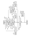
図1はこの発明の実施の形態1による車両用乗員保護装置の制御駆動システムを示す概略的なブロック図であり、図17と同一構成要素には同一符号を付して説明する。
図1において、2は車両1(図17参照)に搭載された乗員保護装置であって、スクイブ(起爆装置)2aと、これによって展開されるエアバッグ2bとからなっている。3は前記乗員保護装置2の制御手段であり、車両1の前部衝突時に生じる衝撃加速度を検出するための加速度センサ3aと、この加速度センサ3aから加速度検出信号をA/Dコンバータによりデジタルデータとして入力するマイクロコンピュータ3bと、このマイクロコンピュータ3bからの出力信号を入力して前記スクイブ2aに点火電流を供給する点火駆動装置3cとを備えた構成となっている。
An embodiment of the present invention will be described below.
FIG. 1 is a schematic block diagram showing a control drive system for a vehicle occupant protection device according to
In FIG. 1,
次に動作について説明する。
車両1の走行時には加速度センサ3aによって衝撃加速度が常に検出され、その加速度検出信号をマイクロコンピュータ3bが入力して演算処理する。すなわち、マイクロコンピュータ3bは、加速度センサ3aから入力した加速度検出信号の大きさを演算してエアバッグ2bを展開すべきか否かを判定する。その判定において、車両の前方衝突時には加速度センサ3aからの入力信号による衝撃加速度が大きくなるので、この場合、マイクロコンピュータ3bからの出力信号で点火駆動装置3cが起動してスクイブ2aに点火電流が通電されることによりエアバッグ2bが展開される。
Next, the operation will be described.
When the
ここで、前記マイクロコンピュータ3bは、車両の通常走行時に想定される最大加速度基準値(加速度上限値)GHおよび最小加速度基準値(加速度下限値)GLを設定する制御基準値設定手段(メモリ)と、前記加速度センサ3aからA/Dコンバータを介して入力する衝撃加速度検出信号に基づく物理量を前記最大加速度基準値GHおよび最小加速度基準値GLと対比・演算する演算手段と、その演算結果の加速度積算値を車両の通常走行時には0に収束すべく復帰処理する復帰処理手段とを主たる構成要素として有するものである。
Here, the
次にマイクロコンピュータ3bの制御プログラムによる動作について説明する。図2は図1の動作を説明するためのフローチャートであって、車両前方衝突時の衝突判定を行う場合を示すものである。なお、マイクロコンピュータ3bが加速度センサ3aから入力する衝撃加速度検出信号を入力Gとし、この入力Gの極性については減速方向の入力が正となるものとして以下に説明する。
まず、車両の通常走行時において、加速度センサ3aが検出する衝撃加速度の絶対値は通常2G以下と小さい。従って、車両の通常走行時にマイクロコンピュータ3bが加速度センサ3aから入力する前記入力Gは、最小加速度基準値GLから最大加速度基準値GHの範囲となる。
Next, the operation by the control program of the
First, during normal driving of the vehicle, the absolute value of the impact acceleration detected by the acceleration sensor 3a is usually as small as 2G or less. Therefore, the input G input from the acceleration sensor 3a by the
そこで、ステップST1では、GL≦入力G≦GHであるか否かのYesまたはNoの判定を行い、Yesの場合にはステップST2に進む。ステップST2では、車両走行時の現時点での加速度積算値V>0であるか否かの判定を行い、V>0の場合はステップST4に進む。ステップST4では、現時点での加速度積算値Vから予め設定された積算基準値G2を減算してステップST6に進む。ステップST6では、ステップST4での減算後の加速度積算値V<0であるか否かを判定し、その減算後の加速度積算値V<0の場合にはステップST9に進む。ステップST9では、0を下回る加速度積算値Vを0とする演算処理が行われる。また、前記ステップST4とステップST6およびステップST9によって、前記加速度積算値Vが0よりも大きい場合には、その加速度積算値Vを0に収束する復帰処理が行われる。 Therefore, in step ST1, a determination of Yes or No is made as to whether GL ≦ input G ≦ GH, and if Yes, the process proceeds to step ST2. In step ST2, it is determined whether or not the current acceleration integrated value V> 0 when the vehicle is traveling. If V> 0, the process proceeds to step ST4. In step ST4, a preset integration reference value G2 is subtracted from the current acceleration integration value V, and the process proceeds to step ST6. In step ST6, it is determined whether or not the acceleration integrated value V <0 after the subtraction in step ST4. If the acceleration integrated value V <0 after the subtraction, the process proceeds to step ST9. In step ST9, a calculation process for setting the acceleration integrated value V below 0 to 0 is performed. If the acceleration integrated value V is greater than 0 in steps ST4, ST6, and ST9, return processing for converging the acceleration integrated value V to 0 is performed.
一方、前記ステップST2での判定結果がNoの場合(現時点での加速度積算値Vが0よりも小さい場合)にはステップST3に進む。このステップST3では、現時点での加速度積算値Vから予め設定された積算基準値G1を加算してステップST5に進む。ステップST5では、前記ステップST3での加算後の加速度積算値V>0であるか否かを判定し、その加算後の加速度積算値V>0の場合にはステップST8に進む。ステップST8では、0を上回る加速度積算値Vを0とする演算処理が行われる。また、前記ステップST3とステップST5およびステップST8によって、前記加速度積算値Vが0よりも小さい場合には、その加速度積算値Vを0に収束する復帰処理が行われる。 On the other hand, when the determination result in Step ST2 is No (when the current acceleration integrated value V is smaller than 0), the process proceeds to Step ST3. In this step ST3, a preset integration reference value G1 is added from the current acceleration integration value V, and the process proceeds to step ST5. In step ST5, it is determined whether or not the acceleration integrated value V> 0 after the addition in step ST3. If the acceleration integrated value V> 0 after the addition, the process proceeds to step ST8. In step ST8, a calculation process for setting the acceleration integrated value V exceeding 0 to 0 is performed. Further, if the acceleration integrated value V is smaller than 0 in step ST3, step ST5, and step ST8, return processing for converging the acceleration integrated value V to 0 is performed.
以上は、車両の通常走行時における衝撃加速度が小さい場合の処理動作であるが、次に、通常走行時以外で大きな衝撃加速度をマイクロコンピュータ3bが入力する場合の処理動作について説明する。
前記ステップST1での判定結果がNoの場合、すなわち、入力GがGLからGHの範囲を超えた大きな衝撃加速度の場合にはステップST7に進む。ステップST7では、現時点での加速度積算値Vに入力Gを加算する。このような処理を実行することで、車両の通常走行時には常に加速度積算値Vが0に収束された状態から車両衝突等による大きな衝撃を受けた際の加速度積算値Vが積算される。この加速度積算値Vは、車両衝突速度が大きい場合、より大きな値となる。
The above is the processing operation when the impact acceleration during normal traveling of the vehicle is small. Next, the processing operation when the
If the determination result in Step ST1 is No, that is, if the input G is a large impact acceleration exceeding the range from GL to GH, the process proceeds to Step ST7. In step ST7, the input G is added to the current acceleration integrated value V. By executing such processing, the integrated acceleration value V when the vehicle is traveling normally is subjected to a large impact such as a vehicle collision from the state where the integrated acceleration value V is always converged to 0. This acceleration integrated value V becomes a larger value when the vehicle collision speed is high.
そして、前記ステップST7での加算処理後にステップST10に進む。ステップST10では、前記ステップST7での加算後の加速度積算値Vと、予め設定された乗員保護装置駆動用の閾値Vthrとの比較演算を行う。その演算の結果、前記加算後の加速度積算値V>閾値Vthrの場合にはステップST11に進んでエアバッグ駆動信号を図1中の点火駆動装置3cに出力する。
Then, after the addition process in step ST7, the process proceeds to step ST10. In step ST10, a comparison operation is performed between the acceleration integrated value V after the addition in step ST7 and a preset threshold value Vthr for driving the passenger protection device. As a result of the calculation, if the integrated acceleration value V> threshold value Vthr after the addition, the process proceeds to step ST11 to output an airbag drive signal to the
次に実際の車両衝突形態において、図2のフローチャートによる演算を実施した場合のエアバッグ駆動信号出力タイミング等について以下に説明する。
車両が高速で衝突した場合と低速で衝突した場合とでは図3(a)に示すような衝撃加速度が発生する。ここで、車両の衝突速度は、衝撃加速度の時間積分によって算出され図3(b)に示すようになる。衝突の大きさは衝突速度の大きさにより評価される。
Next, in the actual vehicle collision mode, the airbag drive signal output timing and the like when the calculation according to the flowchart of FIG. 2 is performed will be described below.
The impact acceleration shown in FIG. 3A occurs when the vehicle collides at a high speed and when the vehicle collides at a low speed. Here, the collision speed of the vehicle is calculated by time integration of the impact acceleration and is as shown in FIG. The magnitude of the collision is evaluated by the magnitude of the collision speed.
前記フローチャートによる演算では、衝突が発生した場合、前記最大加速度基準値(加速度上限側積算値復帰加速度閾値)GHを超えて積算が開始される。衝突中は、ほぼ継続して前記最大加速度基準値GHを超える衝撃加速度が発生するため、演算結果としては図3(b)に示した加速度積分とほぼ同程度の積算値Vが得られる(図3(c)参照)。 In the calculation according to the flowchart, when a collision occurs, integration is started exceeding the maximum acceleration reference value (acceleration upper limit integrated value return acceleration threshold) GH. Since the impact acceleration exceeding the maximum acceleration reference value GH is generated almost continuously during the collision, an integrated value V substantially equal to the acceleration integration shown in FIG. 3 (c)).
乗員保護装置2を作動させる必要がない程度の低速度で車両が衝突した場合には、図3(a)に示すように衝撃加速度が小さく、また、図3(b)に示すように加速度積分は小さくなる。このため、図3(c)に示すように前記積算値Vが、予め設定された駆動信号出力閾値Vthrを超えることはなくなる。従って、エアバッグ駆動信号は出力されない。
When the vehicle collides at such a low speed that it is not necessary to operate the
しかし、車両が高速で衝突した場合には、図3(a)に示すように、低速衝突の際の衝撃加速度が大きくなり、また、図4(b)に示すように加速度積分も大きくなる。すなわち、前記フローチャートに従った演算を実行することで得られた前記積算値Vは、図3(c)のように駆動信号出力閾値Vthrを超える。この際、乗員保護装置2に駆動信号が出力されて乗員保護装置2が駆動されることによりエアバッグ2bが展開される。
However, when the vehicle collides at a high speed, as shown in FIG. 3A, the impact acceleration at the time of the low-speed collision increases, and the acceleration integration also increases as shown in FIG. 4B. That is, the integrated value V obtained by executing the calculation according to the flowchart exceeds the drive signal output threshold Vthr as shown in FIG. At this time, a driving signal is output to the
さらに、乗員保護装置2を作動させる必要がない例としては上記のような衝突以外に、ラフロード走行の場合やブレーキング時に発生する場合が挙げられる。
ラフロード走行時の衝撃加速度波形は図4(a)に示すように振幅の大きな振動波形である。この場合、図4(b)に示すように加速度積分は小さいことが特徴となる。
Furthermore, as an example in which it is not necessary to operate the
The impact acceleration waveform during rough road running is a vibration waveform having a large amplitude as shown in FIG. In this case, the acceleration integral is small as shown in FIG.
このような入力に対して、前記フローチャートに従った演算実行によって得られた前記積算値Vは小さいため、その積算値Vが前記駆動信号出力閾値Vthrを超えることはなく、従って、乗員保護装置2の駆動信号は出力されない。
また、ブレーキング時の衝撃加速度波形は、図4(a)に示すように衝撃加速度発生が小さくなる。ただし、加速度積分は、図4(b)のように大きいことが特徴である。このような入力に対して、前記フローチャートに従った演算では、入力された衝撃加速度Gが前記最小加速度基準値GLと前記最大加速度基準値GHとの間にあるため、加速度積算は実施されず、加速度積算値Vは0を保持する。この結果、加速度積算値Vは駆動信号出力閾値Vthrを超えることはなく、乗員保護装置の駆動信号は出力されない。
Since the integrated value V obtained by executing the calculation according to the flowchart is small with respect to such an input, the integrated value V does not exceed the drive signal output threshold value Vthr. Therefore, the
Further, the impact acceleration waveform during braking reduces the occurrence of impact acceleration as shown in FIG. However, the acceleration integral is large as shown in FIG. For such an input, in the calculation according to the flowchart, since the input impact acceleration G is between the minimum acceleration reference value GL and the maximum acceleration reference value GH, acceleration integration is not performed, The acceleration integrated value V is kept at 0. As a result, the acceleration integrated value V does not exceed the drive signal output threshold Vthr, and the drive signal for the occupant protection device is not output.
また、乗員保護装置2を作動させる必要がない例としては、上記のような物理的な入力以外にも電気的なスプリアスノイズ等が挙げられる。スプリアスノイズは回路上に発生するので、加速度センサ3aからの出力信号に付加される形でマイクロコンピュータ3bに入力される。その入力波形は図5(a)に示すようにパルス的なものが殆どである。この場合、図5(b)に示すように加速度積分は逐次積算されて大きくなるが、前記フローチャートに従った演算では、入力された衝撃加速度Gが前記最小加速度基準値GLと前記最大加速度基準値GHとの間にあるため積算は実施されず、前記加速度積算値Vは0を保持する。この結果、加速度積算値Vは駆動信号出力閾値Vthrを超えることはなく、乗員保護装置の駆動信号は出力されない。
Moreover, as an example which does not need to operate the passenger |
以上説明した実施の形態1によれば、乗員保護装置2の駆動信号出力閾値Vthrをマイクロコンピュータ3bのメモリに予め記憶設定して図2のフローチャートに従った演算を実行するように構成したので、車両が高速で衝突した場合にのみ乗員保護装置2を正確に作動させる制御が可能になるという効果がある。
According to the first embodiment described above, the drive signal output threshold value Vthr of the
なお、上記実施の形態1では、車両の高速衝突を抽出するために前記駆動信号出力閾値Vthrを設定した場合について説明したが、その駆動信号出力閾値Vthrを変更することで、車両の低速衝突を判定させるような感度調整を行うことも可能である。 In the first embodiment, the case where the drive signal output threshold Vthr is set in order to extract a high-speed collision of the vehicle has been described. However, by changing the drive signal output threshold Vthr, a low-speed collision of the vehicle is detected. It is also possible to perform sensitivity adjustment so as to make a determination.
実施の形態2.
図6はこの発明の実施の形態2による乗員保護システムを搭載した車両の前部平面図、図7は図6の乗員保護システムのブロック図であり、図1および図17と同一構成要素には同一符号を付して説明する。
図6において、1は車両、2は車両1に搭載された前方衝突用乗員保護装置、
4は同じく車両1に搭載された後方衝突用乗員保護装置、3は前方衝突用乗員保護装置2および後方衝突用乗員保護装置4を駆動する共通の制御手段である。この制御手段3は、図7に示すように、車両1の衝突時に生じる衝撃加速度を検出するための加速度センサ3aと、この加速度センサ3aから加速度検出信号をA/Dコンバータによりデジタルデータとして入力するマイクロコンピュータ3bと、このマイクロコンピュータ3bからの出力信号を入力して前方衝突用乗員保護装置2および後方衝突用乗員保護装置4をそれぞれ駆動する前方衝突用駆動装置3dおよび後方衝突用駆動装置3eとを備えた構成となっている。ここで、前記前方衝突用乗員保護装置2は一例としてエアバッグが挙げられ、後方衝突用乗員保護装置4は一例としてヘッドレストのような鞭打ち防止装置が挙げられる。なお、前記マイクロコンピュータ3bのメモリには、駆動信号出力閾値Vthr2が予め設定されているものである。
6 is a front plan view of a vehicle equipped with an occupant protection system according to
In FIG. 6, 1 is a vehicle, 2 is a front collision occupant protection device mounted on the
4 is a rear collision occupant protection device mounted on the
次に動作について説明する。
この実施の形態2によるマイクロコンピュータ3bでは、加速度センサ3aから入力した衝撃加速度検出信号の大きさを物理的に演算し、前方衝突用乗員保護装置2および後方衝突用乗員保護装置4の駆動制御を決定する。その決定に基づいて前方衝突用乗員保護装置2を駆動すべき大きな衝撃加速度が入力された場合には、前方衝突用駆動装置3dが前方衝突用乗員保護装置2に駆動信号を出力して前方衝突用乗員保護装置2を駆動する。同様にして、後方衝突用乗員保護装置4を駆動すべき大きな衝撃加速度が入力された場合には、後方衝突用駆動装置3eが後方衝突用乗員保護装置4に駆動信号を出力して後方衝突用乗員保護装置4を駆動する。
Next, the operation will be described.
In the
次にマイクロコンピュータ3bの制御プログラムによる動作について説明する。図8は図7の動作を説明するためのフローチャートであって、車両の前方および後方衝突時の衝突判定を行うための制御プログラムを実行するものである。なお、図8のフローチャートにおいて、ステップST1からステップST11は前記実施の形態1(図2)の場合と同様の演算処理を行うため説明を省略し、ステップST12以降についてのみ説明する。
Next, the operation by the control program of the
マイクロコンピュータ3bには後方衝突用乗員保護装置4を作動すべき駆動信号出力閾値Vthr2が予め設定されていることにより、ステップST12では、前記ステップST1からステップST11によって算出された加速度積算値Vと前記駆動信号出力閾値Vthr2とを比較演算して後方衝突を判定する。その判定の結果、加速度積算値Vが駆動信号出力閾値Vthr2を下回る場合にはステップST13に進む。ステップST13では、後方衝突用乗員保護装置4に駆動信号を出力して後方衝突用乗員保護装置4を駆動する。
このような演算処理を実行することで、車両の後方衝突に対しても衝撃の大きさを判定することが可能となる。なお、前方衝突については前記実施の形態1と同様の演算処理を実行される。
Since the
By executing such arithmetic processing, it is possible to determine the magnitude of the impact even with respect to a rear collision of the vehicle. For forward collision, the same arithmetic processing as in the first embodiment is executed.
次に実際の車両衝突形態において、図8のフローチャートによる演算を実施した場合のエアバッグ駆動信号出力タイミング等を後方衝突の場合についてのみ以下に説明する。後方衝突の場合、負成分(加速成分)の衝撃加速度が発生する。
車両が高速で衝突した場合と低速で衝突した場合とでは図9(a)に示すような衝撃加速度が発生する。ここで、車両の衝突速度は、衝撃加速度の時間積分によって算出され図9(b)に示すようになる。衝突の大きさは衝突速度の大きさにより評価される。
Next, in the actual vehicle collision mode, the airbag drive signal output timing and the like when the calculation according to the flowchart of FIG. 8 is performed will be described below only in the case of a rear collision. In the case of a rear collision, a negative acceleration (acceleration component) impact acceleration occurs.
Impact acceleration as shown in FIG. 9A occurs when the vehicle collides at high speed and when it collides at low speed. Here, the collision speed of the vehicle is calculated by time integration of the impact acceleration and is as shown in FIG. The magnitude of the collision is evaluated by the magnitude of the collision speed.
前記フローチャートによる演算では、衝突が発生した場合、前記最小加速度基準値GLを下回って積算が開始される。衝突中は、ほぼ継続して前記最小加速度基準値GLを下回る衝撃加速度が発生するため、演算結果としては図9(b)に示した加速度積分とほぼ同程度の積算値Vが得られる(図9(c)参照)。 In the calculation according to the flowchart, when a collision occurs, the integration starts below the minimum acceleration reference value GL. During the collision, impact acceleration that is lower than the minimum acceleration reference value GL is generated almost continuously, and therefore, an integrated value V substantially equal to the acceleration integration shown in FIG. 9 (c)).
乗員保護装置を作動させる必要がない程度の低速度で車両が衝突した場合には、図9(a)に示すように衝撃加速度が小さく、また、図9(b)に示すように加速度積分は小さくなる。このため、図9(c)に示すように前記積算値Vが、予め設定された後方駆動信号出力閾値Vthr2を超えることはなくなる。従って、後方衝突用乗員保護装置4の駆動信号は出力されない。
When the vehicle collides at such a low speed that it is not necessary to operate the occupant protection device, the impact acceleration is small as shown in FIG. 9 (a), and the acceleration integral is as shown in FIG. 9 (b). Get smaller. For this reason, as shown in FIG. 9C, the integrated value V does not exceed the preset rear drive signal output threshold Vthr2. Therefore, the drive signal of the rear collision
しかし、車両が高速で衝突した場合には、図9(a)に示すように、低速衝突の際の衝撃加速度が大きくなり、また、図9(b)に示すように加速度積分の絶対値も大きくなる。すなわち、図8のフローチャートに従った演算を実行することで得られた前記積算値Vは、図9(c)にように駆動信号出力閾値Vthr2を下回る。この際には、後方衝突用乗員保護装置4に駆動信号が出力されて後方衝突用乗員保護装置4が駆動される。
However, when the vehicle collides at high speed, as shown in FIG. 9 (a), the impact acceleration at the time of low-speed collision increases, and the absolute value of the acceleration integral also increases as shown in FIG. 9 (b). growing. That is, the integrated value V obtained by executing the calculation according to the flowchart of FIG. 8 is less than the drive signal output threshold Vthr2 as shown in FIG. 9C. At this time, a drive signal is output to the rear collision
さらに、乗員保護装置を作動させる必要がない例としては上記のような衝突以外については、前記実施の形態1の場合と同様のため説明を省略するが、同様に加速度積算値Vは後方用駆動信号出力閾値Vthr2を下回ることはなく、後方衝突用乗員保護装置4の駆動信号は出力されない。
Further, as an example in which it is not necessary to operate the occupant protection device, except for the collision as described above, the description is omitted because it is the same as in the case of the first embodiment, but similarly, the acceleration integrated value V is the rear drive. It does not fall below the signal output threshold Vthr2, and the drive signal for the rear collision
以上説明した実施の形態2によれば、前記実施の形態1によるマイクロコンピュータ3bのメモリに後方衝突に対しての駆動信号出力閾値Vthr2を追加設定して図8のフローチャートに従った演算を実行するように構成したので、車両が高速で衝突した場合にのみ前方衝突用乗員保護装置2は元より後方衝突用乗員保護装置4についても正確に作動させる制御が可能になるという効果がある。
According to the second embodiment described above, the driving signal output threshold Vthr2 for the rear collision is additionally set in the memory of the
実施の形態3.
図10はこの発明の実施の形態3による乗員保護システムを搭載した車両の前部平面図、図11は図10の乗員保護システムのブロック図であり、図1から図9および図17と同一構成要素には同一符号を付して重複説明を省略する。
図10において、5は車両1に搭載された右方衝突用乗員保護装置、6は同じく車両1に搭載された左方衝突用乗員保護装置である。
10 is a front plan view of a vehicle equipped with an occupant protection system according to
In FIG. 10, 5 is a right collision occupant protection device mounted on the
図11において、3fは右方衝突用駆動装置、3gは左方衝突用駆動装置であり、これらの衝突用駆動装置3f,3gはマイクロコンピュータ3bからの出力信号を入力して右方衝突用乗員保護装置5および左方衝突用乗員保護装置6をそれぞれ駆動するものである。ここで、前記各衝突用乗員保護装置5,6は一例として側部衝突用エアバッグが挙げられる。
In FIG. 11, 3f is a right-side collision driving device, 3g is a left-side collision driving device, and these
次に動作について説明する。
この実施の形態3によるマイクロコンピュータ3bでは、加速度センサ3aから入力した衝撃加速度検出信号の大きさを物理的に演算し、右方衝突用乗員保護装置5および左方衝突用乗員保護装置6の駆動制御を決定する。その決定に基づいて右方衝突用乗員保護装置5を駆動すべき大きな衝撃加速度が入力された場合には、右方衝突用駆動装置3fが右方衝突用乗員保護装置5に駆動信号を出力して右方衝突用乗員保護装置5を駆動する。同様にして、左方衝突用乗員保護装置6を駆動すべき大きな衝撃加速度が入力された場合には、左方衝突用駆動装置3gが左方衝突用乗員保護装置6に駆動信号を出力して左方衝突用乗員保護装置6を駆動する。この実施の形態3において、前記マイクロコンピュータ3bのメモリには、右方衝突用乗員保護装置5および左方衝突用乗員保護装置6を駆動すべき駆動信号出力閾値VthrRが予め設定されているものである。
Next, the operation will be described.
In the
次にこの実施の形態3によるマイクロコンピュータ3bの制御動作について説明する。図12は図11の動作を説明するためのフローチャートであって、車両の左右側方の衝突判定を行うための制御プログラムを実行するものである。なお、図12のフローチャートにおいて、ステップST1からステップST9については前記実施の形態2(図8)の場合と同一または相当の演算処理を行うため同一処理部には同一符号を付して説明を省略し、ステップST14以降についてのみ説明する。なお、入力Gの極性については右方向の入力が正となるものとして説明する。
Next, the control operation of the
マイクロコンピュータ3bには右方衝突用乗員保護装置5を作動すべき駆動信号出力閾値VthrRが予め設定されていることにより、ステップST14では、ステップST1からステップST9によって算出された加速度積算値Vと前記右方衝突用駆動信号出力閾値VthrRとを比較演算して右方衝突を判定する。その判定の結果、加速度積算値Vが駆動信号出力閾値VthrRを上回る場合にはステップST15に進む。ステップST15では、右方衝突用乗員保護装置5に駆動信号を出力して右方衝突用乗員保護装置5を駆動する。
Since the
同様にしてステップST16では、左方衝突用乗員保護装置6を作動すべき駆動信号出力閾値VthrLと加速度積算値Vとの比較演算を実行することで左方衝突を判定する。その判定の結果、加速度積算値Vが駆動信号出力閾値VthrLを下回る場合にはステップST17に進む。ステップST17では、左方衝突用乗員保護装置6に駆動信号を出力して左方衝突用乗員保護装置6を駆動する。
このような演算処理を実行することで、車両の左右方向の衝突に対しても衝撃の大きさを判定することが可能となる。
Similarly, in step ST16, a left collision is determined by executing a comparison operation between the drive signal output threshold value VthrL to activate the left collision
By executing such arithmetic processing, it is possible to determine the magnitude of impact even when the vehicle collides in the left-right direction.
次に実際の車両衝突形態において、図12のフローチャートによる演算を実施
した場合のエアバッグ駆動信号出力タイミング等については、前記実施の形態2の場合と同様のため説明を省略するが、加速度積算値Vが各閾値の範囲を超えて乗員保護装置の駆動信号が出力され、乗員保護装置を作動させる必要がない形態入力に対して、加速度積算値Vが各閾値の範囲内にあるため乗員保護装置の駆動信号は出力されない。
Next, in the actual vehicle collision mode, since the airbag drive signal output timing and the like when the calculation according to the flowchart of FIG. 12 is performed are the same as in the second embodiment, description thereof is omitted. Since the driving signal of the occupant protection device is output when V exceeds the range of each threshold, and the integrated acceleration value V is within the range of each threshold for the form input that does not require the occupant protection device to be operated, the occupant protection device No drive signal is output.
以上説明した実施の形態3によれば、前記実施の形態2によるマイクロコンピュータ3bのメモリに左右側方の衝突に対する駆動信号出力閾値VthrR,VthrLを設定して図12のフローチャートに従った演算を実行するように構成したので、車両が高速で衝突した場合にのみ右方衝突用乗員保護装置5は元より左方衝突用乗員保護装置6についても正確に作動させる制御が可能になるという効果がある。
According to the third embodiment described above, the drive signal output thresholds VthrR and VthrL for the left and right side collision are set in the memory of the
実施の形態4.
図13はこの発明の実施の形態4による車両用乗員保護システムに適用されるマイクロコンピュータの制御動作を説明するためのフローチャートであり、図2と同一または相当のステップには同一符号を付して重複説明を省略する。
ステップST1からステップST11については前記実施の形態1で説明したものと同様の処理が実行されるために説明は省略し、より早期にラフロード走行時の衝突との衝突を識別するための追加ステップST18およびステップST19についてのみ説明する。
FIG. 13 is a flowchart for explaining the control operation of the microcomputer applied to the vehicle occupant protection system according to the fourth embodiment of the present invention. The same or corresponding steps as those in FIG. Duplicate explanation is omitted.
Steps ST1 to ST11 are the same as those described in the first embodiment, and therefore will not be described. Additional step ST18 for identifying a collision with a collision during rough road traveling earlier. Only step ST19 will be described.
ステップST1での入力Gが、予め設定された積算値復帰加速度範囲GL〜GHを超えた場合、ステップST18に進む。ステップST18では、入力G<0か否かの判定を行う。その判定の結果、入力G<0の場合にはステップST19に進む。ステップST19では、入力Gが負の値である場合、予め設定された重み付け係数Kが前記入力Gに乗算される。このような処理を行うステップST18およびステップST19を追加することで、負方向の入力Gを重み付けした加速度積算値Vが算出される。 When the input G in step ST1 exceeds the preset integrated value return acceleration range GL to GH, the process proceeds to step ST18. In step ST18, it is determined whether or not the input G <0. As a result of the determination, if the input G <0, the process proceeds to step ST19. In step ST19, when the input G is a negative value, the input G is multiplied by a preset weighting coefficient K. By adding step ST18 and step ST19 for performing such processing, an acceleration integrated value V obtained by weighting the input G in the negative direction is calculated.
次に実際の車両衝突形態において、図13のフローチャートによる演算を実施した場合の駆動信号出力タイミング等について説明する。
乗員保護装置を作動させる必要がある車両衝突時の衝撃加速度波形、および乗員保護装置を作動させる必要がないラフロード走行時の波形は、図14(a)に示すようになる。車両衝突時の衝撃加速度波形は正(減速)成分が主体であり、図14(b)に示すように加速度積分が大きいことが特徴となる。
一方、ラフロード走行時の衝撃加速度波形は図14に示すように振幅が大きな振動波形であり、図14(b)のように加速度積分は小さいことが特徴となる。
Next, drive signal output timing and the like when the calculation according to the flowchart of FIG. 13 is performed in an actual vehicle collision mode will be described.
FIG. 14A shows an impact acceleration waveform at the time of a vehicle collision that requires the occupant protection device to be activated, and a rough road traveling waveform that does not require the occupant protection device to be activated. The impact acceleration waveform at the time of a vehicle collision is mainly composed of a positive (deceleration) component, and is characterized by a large acceleration integration as shown in FIG.
On the other hand, the shock acceleration waveform during rough road running is a vibration waveform with a large amplitude as shown in FIG. 14, and the acceleration integral is small as shown in FIG. 14B.
前記実施の形態1では、ラフロード走行時の加速度積算値が小さく衝突時には大きいことに着目し、閾値を設定することで識別を行った。この場合、識別のタイミングは図14(c)に示すようにラフロード(重み付けなし)との識別を行うためには、VthrA以上の駆動信号出力閾値を予め設定しておく必要がある。このときの識別タイミングは図14(c)のTonAとなる。 In the first embodiment, focusing on the fact that the integrated acceleration value during rough road traveling is small and large during a collision, the identification is performed by setting a threshold value. In this case, as shown in FIG. 14C, it is necessary to set a drive signal output threshold value equal to or higher than VthrA in advance in order to identify rough loading (no weighting) as shown in FIG. The identification timing at this time is TonA in FIG.
この実施の形態4による図13のフローチャートに従った演算では、負方向成分に重み付け係数Kが乗算されているため、ラフロード走行時のような振動波形では負成分に重み付けされることにより、加速度積算値Vは実際の加速度積分に比べて大幅に減少する。一方、衝突波形では、主成分は正成分であるため、減少量はラフロード走行の場合に比べて小さい。このため加速度積算値Vは図14(c)に示すようにラフロード(重み付けあり)では加速度積算値が抑制され、識別する駆動信号出力閾値をVthrBまで下げることが可能となる。この場合、識別タイミングは図14(c)中のTonBとなり、より早いタイミングでの識別が可能となる。 In the calculation according to the flowchart of FIG. 13 according to the fourth embodiment, since the negative direction component is multiplied by the weighting coefficient K, the acceleration component is weighted by weighting the negative component in the vibration waveform during rough road running. The value V is greatly reduced compared to the actual acceleration integral. On the other hand, in the collision waveform, since the main component is a positive component, the amount of decrease is smaller than that in rough road traveling. For this reason, as shown in FIG. 14C, the acceleration integration value V is suppressed in rough loading (with weighting), and the drive signal output threshold value to be identified can be lowered to VthrB. In this case, the identification timing is TonB in FIG. 14C, and identification at an earlier timing is possible.
以上説明した実施の形態4によれば、負成分側の重み付け係数Kが設定された上記演算では、ラフロードのような振動成分の大きな衝撃加速度波形と衝突波形との識別を、より早く遂行することができ、乗員保護装置を的確に作動させる制御が可能となる。 According to the fourth embodiment described above, in the above calculation in which the weighting coefficient K on the negative component side is set, the discrimination between the impact acceleration waveform having a large vibration component such as rough road and the collision waveform is performed earlier. Therefore, it is possible to control the occupant protection device to operate accurately.
なお、前記実施の形態4では、乗員保護装置が1つの場合についてのみ示したが、複数個の乗員保護装置の制御が必要な場合にも同様のフローを追加することで、より早期のタイミングでの作動制御が可能となるものである。 In the fourth embodiment, only one occupant protection device is shown. However, when a plurality of occupant protection devices need to be controlled, a similar flow can be added at an earlier timing. It is possible to control the operation.
実施の形態5.
図15はこの発明の実施の形態5による車両用乗員保護システムに適用されるマイクロコンピュータの制御動作を説明するためのフローチャートであり、図2と同一または相当のステップには同一符号を付して重複説明を省略する。
ステップST1からステップST11については前記実施の形態1で説明したものと同様の処理が実行されるために説明は省略し、加速度積算値を復帰させるための復帰処理を遅延させるタイマ処理のために追加したステップST20,ステップST21,ステップST22についてのみ説明する。
FIG. 15 is a flowchart for explaining the control operation of the microcomputer applied to the vehicle occupant protection system according to the fifth embodiment of the present invention. The same or corresponding steps as those in FIG. Duplicate explanation is omitted.
Steps ST1 to ST11 are the same as those described in the first embodiment, and therefore will not be described. Added for timer processing that delays return processing for returning the acceleration integrated value. Only step ST20, step ST21, and step ST22 will be described.
ステップST1での入力Gが、予め設定された積算値復帰加速度範囲GL〜GHを超えた場合、ステップST22に進む。ステップST22では、時間カウンタTを予め設定した遅延時間Ttimerに設定し直す。
一方、前記入力Gが前記積算値復帰加速度範囲GL〜GHを超えない場合には、ステップST20の処理が実行される。ステップST20では、時間カウンタTからサンプリング時間Δtを減算してステップST21に進む。ステップST21では、前記減算された時間カウンタTを評価し、0以下となった場合にはステップST2に進んで加速度積算値Vを0に収束させる処理が実行される。時間カウンタTが0以上の場合は加速度積算値Vがそのまま保持されてステップST10に進む。
このような処理ステップを追加することで、加速度積算値Vの復帰処理(加速度積算値を0に収束させる)タイミングを調整できる。
If the input G in step ST1 exceeds the preset integrated value return acceleration range GL to GH, the process proceeds to step ST22. In step ST22, the time counter T is reset to a preset delay time Ttimer.
On the other hand, when the input G does not exceed the integrated value return acceleration range GL to GH, the process of step ST20 is executed. In step ST20, the sampling time Δt is subtracted from the time counter T, and the process proceeds to step ST21. In step ST21, the subtracted time counter T is evaluated. If the time counter T is less than or equal to 0, the process proceeds to step ST2 where a process of converging the acceleration integrated value V to 0 is executed. If the time counter T is equal to or greater than 0, the acceleration integrated value V is held as it is, and the process proceeds to step ST10.
By adding such processing steps, it is possible to adjust the timing for returning the acceleration integrated value V (the acceleration integrated value is converged to 0).
次に実際の車両衝突形態において、図15のフローチャートによる演算を実施した場合の処理内容について説明する。
前記実施の形態1から実施の形態4では、衝突時の衝撃加速度が連続発生するケースについて説明したが、実際の衝突では車両の衝突モードにより衝撃加速度波形が異なるほか、車両の各構成部品のレイアウトにより同じ衝突形態においても衝撃加速度は異なる。
Next, the processing contents when the calculation according to the flowchart of FIG. 15 is performed in the actual vehicle collision mode will be described.
In the first embodiment to the fourth embodiment, the case where the impact acceleration at the time of collision occurs continuously has been described. However, in the actual collision, the impact acceleration waveform differs depending on the vehicle collision mode, and the layout of each component of the vehicle Thus, even in the same collision mode, the impact acceleration is different.
図16は前記実施の形態5による乗員保護システムに適用される衝突判定方法における演算内容を実際の衝突形態に適用した場合の演算結果である。
図16(a)のように衝撃加速度波形の第1波と第2波との発生Gが小さい領域が発生するような車両および衝突形態について説明する。
図16(a)のような衝撃加速度波形の場合、加速度積分は図16(b)のようになる。
図16(c1)は、前記実施の形態1から前記実施の形態4の演算を適用した場合の演算モードについて記載したもので、積算値復帰加速度範囲GL〜GHを超える場合は積算処理が実行され、積算値復帰加速度範囲GL〜GH以内の場合は積算値の復帰処理(加速度積算値を0に収束させる)タイミングを示している。
FIG. 16 shows a calculation result when the calculation content in the collision determination method applied to the passenger protection system according to the fifth embodiment is applied to an actual collision mode.
A vehicle and a collision mode in which a region where the generation G of the first wave and the second wave of the impact acceleration waveform is small as illustrated in FIG.
In the case of the impact acceleration waveform as shown in FIG. 16A, the acceleration integration is as shown in FIG.
FIG. 16 (c1) shows a calculation mode when the calculations of the first to fourth embodiments are applied. When the calculation value exceeds the integrated value return acceleration range GL to GH, the integration process is executed. In the integrated value return acceleration range GL to GH, the integrated value return processing (acceleration integrated value converges to 0) timing is shown.
前記実施の形態1から前記実施の形態4の演算を適用した場合の加速度積算値vは、図16(c2)に示すように演算結果では、衝撃加速度Gが積算値復帰加速度範囲GL〜GHにある時間(T1〜T2)では加速度積算値Vが0に収束される波形となり、実際の加速度積分よりも減衰する。このため、図15のフローチャートに従った演算によれば、図16(c1)のように衝撃加速度が積算値復帰加速度範囲GL〜GH内に入ってからTtimer分は積算値復帰処理が保留される。衝撃加速度Gが積算値復帰加速度範囲GL〜GHにある時間(T1〜T2)では加速度積算値Vが保留されるため、図16(c2)のように実際の加速度積分を、より正確に再現することが可能となる。 As shown in FIG. 16 (c2), the acceleration integrated value v when the calculations of the first to fourth embodiments are applied is calculated as follows. In the calculation result, the impact acceleration G falls within the integrated value return acceleration ranges GL to GH. At a certain time (T1 to T2), the acceleration integrated value V becomes a waveform that converges to 0 and attenuates more than the actual acceleration integration. For this reason, according to the calculation according to the flowchart of FIG. 15, the integrated value return processing is suspended for Ttime after the impact acceleration enters the integrated value return acceleration range GL to GH as shown in FIG. . Since the acceleration integrated value V is suspended during the time (T1 to T2) in which the impact acceleration G is in the integrated value return acceleration range GL to GH, the actual acceleration integration is reproduced more accurately as shown in FIG. It becomes possible.
なお、前記実施の形態5では、乗員保護装置が1つの場合についてのみ示したが、複数個の乗員保護装置の制御が必要な場合にも同様のフローを追加することで、積算値復帰処理の遅延処理が可能となる。また、前記各実施の形態では、乗員保護装置として、エアバッグ,サイドエアバッグについて説明したが、シートベルトプリテンショナーや、むち打ち防止用のヘッドレストショックアブソーバなどに用いることも可能である。 In the fifth embodiment, only one occupant protection device is shown. However, when the control of a plurality of occupant protection devices is necessary, a similar flow is added, so that the integrated value restoration process is performed. Delay processing is possible. In each of the above embodiments, the airbag and the side airbag have been described as the occupant protection device. However, the occupant protection device may be used for a seat belt pretensioner, a headrest shock absorber for preventing whiplash, and the like.
1 車両、2 乗員保護装置、2a スクイブ(起爆装置)、2b エアバッグ、3 制御手段、3a 加速度センサ、3b マイクロコンピュータ、3c 点火駆動装置、3d 前方衝突用駆動装置、3e 後方衝突用駆動装置、3f 右方衝突用駆動装置、3g 左方衝突用駆動装置、4 後方衝突用乗員保護装置、5 右方衝突用乗員保護装置、6 左方衝突用乗員保護装置。 1 vehicle, 2 occupant protection device, 2a squib (detonation device), 2b air bag, 3 control means, 3a acceleration sensor, 3b microcomputer, 3c ignition drive device, 3d front collision drive device, 3e rear collision drive device, 3f Driving device for right collision, 3g Driving device for left collision, 4 Occupant protection device for rear collision, 5 Occupant protection device for right collision, 6 Occupant protection device for left collision.
Claims (4)
前記乗員保護制御手段は、前記加速度信号に基づく物理量を演算し、車両の通常走行時の前記物理量の最大基準値および最小基準値をあらかじめ設定し、その物理量が前記最大基準値から前記最小基準値の範囲内のとき、加速度積算値が正の値のときにその加速度積算値から、現時点での加速度積算値に対して予め設定された積算基準値の減算を実行し、前記物理量が前記最大基準値から前記最小基準値の範囲内のとき、加速度積算値が負の値のときにその加速度積算値から、現時点での加速度積算値に対して予め設定された積算基準値の加算を実行する機能を有することを特徴とする車両用乗員保護システム。 An occupant protection device mounted on a vehicle, and an occupant protection control unit that has an acceleration sensor that detects acceleration due to an impact at the time of a vehicle collision, and that inputs an acceleration signal from the acceleration sensor to control and drive the occupant protection device. In the vehicle occupant protection system provided,
The occupant protection control means calculates a physical quantity based on the acceleration signal, presets a maximum reference value and a minimum reference value of the physical quantity during normal driving of the vehicle, and the physical quantity is calculated from the maximum reference value to the minimum reference value. When the acceleration integrated value is a positive value , subtracting a preset integration reference value from the acceleration integrated value to the current acceleration integrated value is performed, and the physical quantity is the maximum reference A function that, when the value is within the range of the minimum reference value from the value , adds the preset integration reference value to the current acceleration integration value from the acceleration integration value when the acceleration integration value is negative A vehicle occupant protection system comprising:
Priority Applications (1)
| Application Number | Priority Date | Filing Date | Title |
|---|---|---|---|
| JP2008192215A JP4800351B2 (en) | 2008-07-25 | 2008-07-25 | Vehicle occupant protection system |
Applications Claiming Priority (1)
| Application Number | Priority Date | Filing Date | Title |
|---|---|---|---|
| JP2008192215A JP4800351B2 (en) | 2008-07-25 | 2008-07-25 | Vehicle occupant protection system |
Related Parent Applications (1)
| Application Number | Title | Priority Date | Filing Date |
|---|---|---|---|
| JP2001142151A Division JP4416961B2 (en) | 2001-05-11 | 2001-05-11 | Vehicle occupant protection system |
Publications (2)
| Publication Number | Publication Date |
|---|---|
| JP2008254734A JP2008254734A (en) | 2008-10-23 |
| JP4800351B2 true JP4800351B2 (en) | 2011-10-26 |
Family
ID=39978720
Family Applications (1)
| Application Number | Title | Priority Date | Filing Date |
|---|---|---|---|
| JP2008192215A Expired - Lifetime JP4800351B2 (en) | 2008-07-25 | 2008-07-25 | Vehicle occupant protection system |
Country Status (1)
| Country | Link |
|---|---|
| JP (1) | JP4800351B2 (en) |
Families Citing this family (2)
| Publication number | Priority date | Publication date | Assignee | Title |
|---|---|---|---|---|
| JP5155936B2 (en) * | 2009-05-22 | 2013-03-06 | トヨタ自動車株式会社 | Collision determination device and activation control device for occupant protection device |
| JP6597401B2 (en) * | 2016-03-01 | 2019-10-30 | 株式会社デンソー | Collision determination device |
Family Cites Families (5)
| Publication number | Priority date | Publication date | Assignee | Title |
|---|---|---|---|---|
| JP2776161B2 (en) * | 1992-08-04 | 1998-07-16 | トヨタ自動車株式会社 | Collision detection device |
| JP3768268B2 (en) * | 1995-07-11 | 2006-04-19 | オートリブ・ジャパン株式会社 | Vehicle side collision detection device |
| JP4003003B2 (en) * | 1997-12-27 | 2007-11-07 | オートリブ・ジャパン株式会社 | Side airbag device |
| JPH11198699A (en) * | 1998-01-19 | 1999-07-27 | Toyota Motor Corp | Rearmost seat for vehicle |
| JP3991295B2 (en) * | 1998-05-28 | 2007-10-17 | マツダ株式会社 | Steering control device for vehicle collision |
-
2008
- 2008-07-25 JP JP2008192215A patent/JP4800351B2/en not_active Expired - Lifetime
Also Published As
| Publication number | Publication date |
|---|---|
| JP2008254734A (en) | 2008-10-23 |
Similar Documents
| Publication | Publication Date | Title |
|---|---|---|
| JP4416961B2 (en) | Vehicle occupant protection system | |
| US7416042B2 (en) | Method for triggering a two-stage belt tensioner | |
| US6438475B1 (en) | Crash detection system | |
| KR100196452B1 (en) | Crash sensor | |
| JP6333283B2 (en) | Method and apparatus for controlling actuatable restraint devices using multi-region enhanced identification | |
| US20060064220A1 (en) | Object struck discrimination system and protection system | |
| US20120072078A1 (en) | Collision determining apparatus for vehicle | |
| JP4918503B2 (en) | Validity of side impact using lateral velocity | |
| JPH04361163A (en) | Vehicle collision detector | |
| US6324454B1 (en) | Activation control apparatus of occupant safety | |
| US20060064219A1 (en) | Object struck discrimination system and protection system | |
| US20150314744A1 (en) | Method and device for activating a pedestrian protection means for a vehicle, and restraint system for a vehicle | |
| CN111132875B (en) | Method for generating a trigger signal for triggering at least one safety function of a motor vehicle | |
| JP4800351B2 (en) | Vehicle occupant protection system | |
| US20160325702A1 (en) | Control device for occupant protection device | |
| JP2004536742A (en) | Vehicle impact detection system and control method | |
| US20100256873A1 (en) | Method and control unit for triggering occupant protection means for a vehicle | |
| JP2008534365A (en) | Discriminating method for pedestrian protection system | |
| US20080185825A1 (en) | Device For Triggering a Second Airbag Stage | |
| US8108107B2 (en) | Safety system | |
| JP2019027833A (en) | Collision detection device | |
| US7660655B2 (en) | Supplemental restraint deployment method with displacement-based deployment immunity | |
| US7376502B2 (en) | Device for triggering a restraining system in a vehicle | |
| JP3118980B2 (en) | Vehicle collision determination device | |
| JP5511528B2 (en) | Collision signal processing device for vehicle front collision acceleration sensor |
Legal Events
| Date | Code | Title | Description |
|---|---|---|---|
| A621 | Written request for application examination |
Free format text: JAPANESE INTERMEDIATE CODE: A621 Effective date: 20080725 |
|
| A977 | Report on retrieval |
Free format text: JAPANESE INTERMEDIATE CODE: A971007 Effective date: 20101224 |
|
| A131 | Notification of reasons for refusal |
Free format text: JAPANESE INTERMEDIATE CODE: A131 Effective date: 20110104 |
|
| A521 | Written amendment |
Free format text: JAPANESE INTERMEDIATE CODE: A523 Effective date: 20110217 |
|
| TRDD | Decision of grant or rejection written | ||
| A01 | Written decision to grant a patent or to grant a registration (utility model) |
Free format text: JAPANESE INTERMEDIATE CODE: A01 Effective date: 20110726 |
|
| A01 | Written decision to grant a patent or to grant a registration (utility model) |
Free format text: JAPANESE INTERMEDIATE CODE: A01 |
|
| A61 | First payment of annual fees (during grant procedure) |
Free format text: JAPANESE INTERMEDIATE CODE: A61 Effective date: 20110803 |
|
| FPAY | Renewal fee payment (event date is renewal date of database) |
Free format text: PAYMENT UNTIL: 20140812 Year of fee payment: 3 |
|
| R150 | Certificate of patent or registration of utility model |
Ref document number: 4800351 Country of ref document: JP Free format text: JAPANESE INTERMEDIATE CODE: R150 Free format text: JAPANESE INTERMEDIATE CODE: R150 |
|
| R250 | Receipt of annual fees |
Free format text: JAPANESE INTERMEDIATE CODE: R250 |
|
| R250 | Receipt of annual fees |
Free format text: JAPANESE INTERMEDIATE CODE: R250 |
|
| R250 | Receipt of annual fees |
Free format text: JAPANESE INTERMEDIATE CODE: R250 |
|
| R250 | Receipt of annual fees |
Free format text: JAPANESE INTERMEDIATE CODE: R250 |
|
| R250 | Receipt of annual fees |
Free format text: JAPANESE INTERMEDIATE CODE: R250 |
|
| R250 | Receipt of annual fees |
Free format text: JAPANESE INTERMEDIATE CODE: R250 |
|
| EXPY | Cancellation because of completion of term |