JP4800029B2 - Door for evacuation in case of earthquake disaster - Google Patents
Door for evacuation in case of earthquake disaster Download PDFInfo
- Publication number
- JP4800029B2 JP4800029B2 JP2005373699A JP2005373699A JP4800029B2 JP 4800029 B2 JP4800029 B2 JP 4800029B2 JP 2005373699 A JP2005373699 A JP 2005373699A JP 2005373699 A JP2005373699 A JP 2005373699A JP 4800029 B2 JP4800029 B2 JP 4800029B2
- Authority
- JP
- Japan
- Prior art keywords
- door
- evacuation
- stopper
- building
- auxiliary
- Prior art date
- Legal status (The legal status is an assumption and is not a legal conclusion. Google has not performed a legal analysis and makes no representation as to the accuracy of the status listed.)
- Expired - Fee Related
Links
Images


Description
本発明は、地震災害時の避難対応ドアに関する。詳しくは地震災害時の避難に対応したマンション等の建築物の出入り口ドアに係るものである。 The present invention relates to an evacuation support door at the time of an earthquake disaster. Specifically, it relates to doorways of buildings such as condominiums that respond to evacuation in the event of an earthquake disaster.
従来より、家屋、マンション等の建築物の出入り口には、建築物と一体となった枠体及び軽金属等の材質を用いて製造された建築物用ドアが取り付けられている。このような建築物に地震等により大きな外力が作用した場合には建築物には歪みが発生し、この歪みにより建築物用ドアの枠体が面内変形を発生する。 Conventionally, a door for a building manufactured using a material such as a frame body and light metal integrated with a building is attached to an entrance of a building such as a house or a condominium. When a large external force is applied to such a building due to an earthquake or the like, the building is distorted, and the frame of the building door is deformed in the plane by the distortion.
これにより枠体がドア主体と接触すると摩擦により開閉機能が低下し、同時に施錠装置が変形することによって解錠し難くなることによりドア主体が開放できない状態に陥り、室内の人間が閉じ込まれて非常に危険な状態となる。 As a result, when the frame body comes into contact with the door main body, the opening / closing function is lowered due to friction, and at the same time, the locking device is deformed, so that it becomes difficult to unlock the door main body, so that the door main body cannot be opened, and the indoor person is closed. It becomes very dangerous.
そこで上記のような危険を回避するべく、例えば図8に示すような耐地震用ドアが発明されている。この耐地震用ドアでは、扉枠101は扉102の上下および戸先側との間に、従来に比べて大きな隙間103が形成されるとともに、戸先側の戸当り部104に扉102の内部に突出するコの字形の鍵受け金105が設けられ、扉102は戸先側に鍵受け金105を挿入させ、かつ鍵受け金105を扉102の幅方向に移動させ得る開口106を形成され、また戸先側の扉内には鍵前本体107が設けられ、前記鍵受け金105はラッチ108とデッドボルトとを挿通させるとともに、それらの上下に十分な空間部を形成した構成とされる(特許文献1参照。)。
Therefore, in order to avoid the above danger, an earthquake resistant door as shown in FIG. 8, for example, has been invented. In this earthquake-resistant door, the
しかしながら前記のような耐地震用ドアでは、一般では扉および扉枠の大きさが規格により定められている場合が多く、特にマンションなどのコンクリート建築物の扉枠を既設のものと取り替えるにはコンクリート壁を取り崩さなければならない問題が生じる恐れがある。 However, in the case of the earthquake resistant door as described above, in general, the size of the door and the door frame is often determined by the standard. There is a risk of problems that have to break down the walls.
また、扉と扉枠との上下および戸先側に隙間を設けることによって、例えばその隙間にくぎ抜きなどの金具を差し込んでテコの原理によってドアを解錠し易くなるなど防犯性において問題が生じる。 In addition, by providing gaps on the top and bottom of the door and the door frame and on the door tip side, a problem arises in crime prevention, for example, by inserting metal fittings such as nails into the gap and making it easier to unlock the door by the lever principle .
本発明は、以上の点に鑑みて創案されたものであって、マンションなどのコンクリート建築物の既設の扉枠に対して、扉を取り替えることにより地震時において扉枠体内に面内変形が生じてもドアの開放が可能な地震災害時の避難対応ドアを提供することを目的とするものである。 The present invention was devised in view of the above points, and in-plane deformation occurs in the door frame body during an earthquake by replacing the door with respect to an existing door frame of a concrete building such as a condominium. However, the purpose is to provide an evacuation door that can be opened even during an earthquake disaster.
上記の目的を達成するために、本発明に係る地震災害時の避難対応ドアは、建築物と一体となって形成される枠体内に、外周枠で囲まれ、かつボルト出没形式の施錠装置が具備されるドア本体を開閉自在に取り付けられた建築物用の金属製横開きドアにおいて、前記ドア本体に貫設される人間が脱出可能な大きさとされる緊急用出入口と、前記緊急用出入口内に屋内側より嵌合され、かつ止め金具によってドア本体に取付けられる補助ドアを備える。 In order to achieve the above object, the door for evacuation at the time of earthquake disaster according to the present invention is surrounded by an outer peripheral frame in a frame formed integrally with a building, and a locking device of a bolt in / out type is provided. A metal side opening door for a building to which the door body is provided so that it can be opened and closed, and an emergency doorway that is sized to allow humans to penetrate through the door body, and the inside of the emergency doorway And an auxiliary door that is fitted from the indoor side and is attached to the door body by a stopper.
ここで、地震災害時に建築物に歪みが生じてドア本体と枠体に外力が生じて変形してドア本体を開くことができなくなった場合において、緊急用出入口の内部側に形成される段差部と補助ドアに形成される嵌合部とを隙間を設けた状態で止め金具によって取り付けることにより、補助ドアに作用する変形モーメントが吸収分散されて変形を防止することが可能となる。 Here, when an earthquake disaster causes distortion in the building, external force is generated in the door body and the frame, and the door body cannot be opened due to deformation and cannot be opened. And the fitting portion formed on the auxiliary door are attached with a stopper in a state where a gap is provided, the deformation moment acting on the auxiliary door is absorbed and dispersed, and the deformation can be prevented.
また、補助ドアに十字形状の溝穴を設け、この溝穴に止め金具を差し込むことにより、ドア本体に対して上下方向、あるいは左右方向への変形モーメントが作用した場合に、止め金具が溝穴を移動して止め金具への負荷を軽減することで止め金具の変形を防止することが可能となる。 In addition, a cross-shaped slot is provided in the auxiliary door, and the stopper is inserted into the slot when a vertical or horizontal deformation moment acts on the door body by inserting the stopper into the slot. It is possible to prevent deformation of the fastener by moving the and reducing the load on the fastener.
本発明の地震災害時の避難対応ドアによれば、建築物に地震等により大きな外力が作用し、ドアが開かなくなった場合に、内部より補助ドアを取り外してドア本体に開口される緊急用出入口より屋外へ避難することが可能となる。 According to the evacuation door at the time of an earthquake disaster of the present invention, when a large external force acts on the building due to an earthquake or the like and the door cannot be opened, the emergency door is opened to the door body by removing the auxiliary door from the inside It is possible to evacuate more outdoors.
また、補助ドアと緊急用出入口との嵌合の際には、隙間を設けるとともに、止め金具が移動できる十字形状の溝穴を設けることによって地震時におけるドア本体の変形モーメントに対して補助ドアに作用するモーメントを吸収分散して補助ドアおよび止め金具の変形を防止し、レンチなどの工具によって止め金具を容易に取り外すことができる構成とするものである。 In addition, when the auxiliary door and the emergency doorway are fitted, a clearance is provided and a cross-shaped slot that allows the stopper to move is provided to the auxiliary door against the deformation moment of the door body during an earthquake. The acting moment is absorbed and dispersed to prevent deformation of the auxiliary door and the stopper, and the stopper can be easily removed with a tool such as a wrench.
以下、本発明の実施の形態を図面を参酌しながら説明し、本発明の理解に供する。
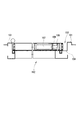
図1に、本発明を適用した地震災害時の避難対応ドアの一例を説明するための外部側からの正面図、図2に、図1における内部側からの正面図、図3に、図1A−A線における断面図を示す。
Hereinafter, embodiments of the present invention will be described with reference to the drawings to provide an understanding of the present invention.
FIG. 1 is a front view from the outside for explaining an example of an evacuation door at the time of an earthquake disaster to which the present invention is applied, FIG. 2 is a front view from the inside in FIG. 1, and FIG. Sectional drawing in the -A line is shown.
ここで示す避難対応ドア1は、ドア本体2と該ドア本体2の上部、下部および両側部を包囲し、建築物と一体に取り付けられる枠体3とから構成される。このドア本体2は、支持側縁部4の上方、下方で二組のヒンジ5により枠体3に回動自在な状態で軸支されており、開閉側縁部6には施錠装置7およびノブ8が装着されている。
The evacuation-compatible door 1 shown here includes a door
前記ドア本体2は、例えば内部にハニカムコア材を有し、外板は薄鋼板であるサンドイッチパネルの周囲を外周枠9により構成されている。また、前記枠体3は、ドア本体2の上部、下部および両側面を確保して包囲するステンレス、鉄、アルミ等の金属材により製造される。
Before
そこでドア本体2の外面には人間が脱出可能な幅および高さを有する緊急用出入口10が開設される。そしてこの緊急用出入口10に内部側から補助ドア11を止め金具12によって取り付ける構成とするものである。
Therefore, an
また、補助ドア11の内部側の下部には止め金具12によるネジ締結を開放するための工具と手袋等が収納される工具等収納部13が装着され、地震等によってドア本体2が開かなくなった際に、工具等収納部13を開いてレンチ等の工具によって止め金具12による締結を解除して、補助ドア11を緊急用出入口10から取り外して、該緊急用出入口10より屋外へ脱出できる構成とするものである。
In addition, a tool storage portion 13 for storing a tool and gloves for releasing the screw fastening by the
ここで、図4および図5に示すようにドア本体2の緊急用出入口10の内部側の開口周縁に沿って段差部14が設けられ、この段差部14の外側周囲には、ネジ孔15が所定間隔ごとに穿孔される。
Here, as shown in FIG. 4 and FIG. 5, a
次に、補助ドア11の各辺に沿って前記段差部14に嵌め合わされる段差状の嵌合部16が形成される。この嵌合部16の外側周囲には前記段差部14周囲に穿孔されたネジ孔15と同じとなる位置に十字形状の溝穴17が開設されるものである。
Next, a step-
また、止め金具12は図6(イ)、(ロ)に示すように、前記十字形状の溝穴17の長さより大きい外径とした円板状の頭部18と前記ネジ孔15に螺合するネジ部19から構成され、更に頭部18の中央には四角形状のレンチ穴20が開口されるものである。
Further, as shown in FIGS. 6A and 6B, the
また、前記補助ドア11は内部にウレタン等のバックアップ材21が介装されることによって軽量、かつ強度を持たせた構造とするものである。
The
そこで図4および図5に示すように、ドア本体2の緊急用出入口10の内周縁に沿って形成される段差部14に対して地震などによる変形モーメントを吸収分散するゴムなどのシール部材22を介して補助ドア11の嵌合部16を嵌め合わさるようにし、更に止め金具12によって補助ドア11をドア本体2に螺着する。
Therefore, as shown in FIGS. 4 and 5, a sealing member 22 such as rubber that absorbs and disperses a deformation moment due to an earthquake or the like with respect to the
ここで、補助ドア11によって緊急用出入口10が嵌め合わせられる場合に、ドア本体2の段差部14端と補助ドア11の嵌合部16端とに図中W長さの隙間が生じるように構成されることにより地震などによるドア本体2への変形モーメントに対して補助ドア11が影響を受けない構成とするものである。
Here, when the
また、補助ドア11に十字形状の溝穴17を設け、この溝穴17に止め金具12のネジ部19を差し込むことにより、ドア本体2に対して上下方向、あるいは左右方向への変形モーメントが作用した場合に、止め金具12が溝穴17を移動して止め金具12への負荷を軽減することで止め金具12の変形を防いで、止め金具12の取り外しに支障を来たさない構成とするとともに、補助ドア11の変形を防ぐものとする。
Further, the
このように本発明では、ドア本体2に開口される緊急用出入口10に対して補助ドア11を嵌め合わせるものではなく、緊急用出入口10の内部側に形成される段差部14と補助ドア11に形成される嵌合部16とを隙間を設けた状態で止め金具12によって取り付けることにより、地震時におけるドア本体2への変形モーメントに対してシール部材22と隙間によって変形モーメントを吸収分散して補助ドア11の変形を防ぐことが可能となる。
Thus, in the present invention, the
したがって、地震災害時に建築物に歪みが生じてドア本体2と枠体3に外力が生じて変形してドア本体2を開くことができなくなった場合において、補助ドア11の下部に設けられる工具等収納部13を開いて図7(イ)、(ロ)で示すようなレンチ工具23および手袋(図示せず。)を取り出し、手袋を着用してレンチ工具23によって止め金具12を取り外す。
Accordingly, in the event that the building is distorted due to an earthquake disaster and an external force is generated on the
この際には、十字形状の溝穴17によって止め金具12への変形が防止されることによって止め金具12を支障なく取り外して補助ドア11を外して緊急用出入口10より外部へ脱出することが可能となる。
At this time, the cross-shaped slot 17 prevents deformation of the
なお、本発明の避難対応ドアはマンション等の居住用玄関ドアの他に、非常階段のドアや自動シャッター横に設けられる出入り口ドアにも活用することができるものである。 The evacuation-compatible door of the present invention can be used not only for an entrance door for a residence such as an apartment, but also for an emergency staircase door or an entrance door provided next to an automatic shutter.
また、補助ドア11の外部面に、絵柄や色彩を施すことによって意匠性に優れたドアとしても活用することができる。
Moreover, it can utilize also as a door excellent in the designability by giving a pattern and a color to the external surface of the
1 避難対応ドア
2 ドア本体
3 枠体
4 支持側縁部
5 ヒンジ
6 開閉側縁部
7 施錠装置
8 ノブ
9 外周枠
10 緊急用出入口
11 補助ドア
12 止め金具
13 工具等収納部
14 段差部
15 ネジ孔
16 嵌合部
17 溝穴
18 頭部
19 ネジ部
20 レンチ穴
21 バックアップ材
22 シール部材
23 レンチ工具
DESCRIPTION OF SYMBOLS 1
Claims (1)
前記ドア本体に貫設された人間が脱出可能な大きさとされた緊急用出入口と、
該緊急用出入口の屋内側周囲に沿って形成された段差部と、
該段差部の周囲に穿孔されたネジ孔と、
前記段差部と嵌合する段差状の嵌合部が形成されると共に、前記ネジ孔に対応する位置に十字形状の溝穴が開口された補助ドアと、
前記段差部と前記嵌合部との間に隙間が形成された状態で、前記ネジ孔と前記溝穴とを螺着する止め金具と、
前記補助ドアの屋内側に設けられると共に、前記止め金具によるネジ締結を開放するための工具が収納可能とされた収納部とを備える
ことを特徴とする地震災害時の避難対応ドア。 In a metal side opening door for a building in which a door body surrounded by an outer peripheral frame and provided with a bolt in / out locking device is detachably mounted in a frame formed integrally with a building. ,
And emergency doorway pierced been human beings is a size that can escape is to the door body,
A step formed along the indoor side periphery of the emergency doorway;
A screw hole drilled around the step,
An auxiliary door in which a step-like fitting portion that fits with the step portion is formed, and a cross-shaped slot is opened at a position corresponding to the screw hole,
In a state where a gap is formed between the stepped portion and the fitting portion, a fastener for screwing the screw hole and the groove hole,
A door for evacuation at the time of an earthquake disaster , which is provided on the indoor side of the auxiliary door and includes a storage portion in which a tool for opening a screw fastening by the stopper can be stored .
Priority Applications (1)
| Application Number | Priority Date | Filing Date | Title |
|---|---|---|---|
| JP2005373699A JP4800029B2 (en) | 2005-12-27 | 2005-12-27 | Door for evacuation in case of earthquake disaster |
Applications Claiming Priority (1)
| Application Number | Priority Date | Filing Date | Title |
|---|---|---|---|
| JP2005373699A JP4800029B2 (en) | 2005-12-27 | 2005-12-27 | Door for evacuation in case of earthquake disaster |
Publications (2)
| Publication Number | Publication Date |
|---|---|
| JP2007177399A JP2007177399A (en) | 2007-07-12 |
| JP4800029B2 true JP4800029B2 (en) | 2011-10-26 |
Family
ID=38302855
Family Applications (1)
| Application Number | Title | Priority Date | Filing Date |
|---|---|---|---|
| JP2005373699A Expired - Fee Related JP4800029B2 (en) | 2005-12-27 | 2005-12-27 | Door for evacuation in case of earthquake disaster |
Country Status (1)
| Country | Link |
|---|---|
| JP (1) | JP4800029B2 (en) |
Families Citing this family (1)
| Publication number | Priority date | Publication date | Assignee | Title |
|---|---|---|---|---|
| CN114033069A (en) * | 2021-12-09 | 2022-02-11 | 江苏晟唐合智建筑设计有限公司 | Structure for hiding width of door frame by wall |
Family Cites Families (8)
| Publication number | Priority date | Publication date | Assignee | Title |
|---|---|---|---|---|
| JPS5651971U (en) * | 1979-09-29 | 1981-05-08 | ||
| JPS62180187U (en) * | 1986-05-06 | 1987-11-16 | ||
| JPH0752654B2 (en) * | 1987-07-28 | 1995-06-05 | 株式会社ユアサコーポレーション | Lead acid battery |
| JPH0635786B2 (en) * | 1988-09-21 | 1994-05-11 | 株式会社日本アルミ | Sash mounting structure |
| JP2758670B2 (en) * | 1989-09-26 | 1998-05-28 | 株式会社クラレ | Polyurethane, production method thereof, and polyester diol used therefor |
| JPH06146745A (en) * | 1992-11-10 | 1994-05-27 | Kubota Corp | Bathroom door |
| JPH10311185A (en) * | 1997-05-13 | 1998-11-24 | Sansho:Kk | Door device for escaping in case of earthquake disaster |
| JP3760990B2 (en) * | 2001-11-09 | 2006-03-29 | 豊和工業株式会社 | Frame structure of door device |
-
2005
- 2005-12-27 JP JP2005373699A patent/JP4800029B2/en not_active Expired - Fee Related
Also Published As
| Publication number | Publication date |
|---|---|
| JP2007177399A (en) | 2007-07-12 |
Similar Documents
| Publication | Publication Date | Title |
|---|---|---|
| CA2295296A1 (en) | Two portion frame | |
| KR20070058026A (en) | Door structure for preventing confinement in room and door modifying member for the door structure | |
| JP4800029B2 (en) | Door for evacuation in case of earthquake disaster | |
| JP3141378U (en) | Anti-seismic door | |
| KR102121020B1 (en) | Device for preventing thermal deformation of fire door | |
| KR102464988B1 (en) | Fall arrestor for windows | |
| KR102085754B1 (en) | Safety door assembly for disaster | |
| US20170138100A1 (en) | Doorway entry prevention device | |
| JP4022232B2 (en) | Remodeling doors to prevent indoor containment | |
| WO2011067444A1 (en) | Instant opening mechanism for closures | |
| JPH0988446A (en) | Door device | |
| JPS608065Y2 (en) | earthquake resistant door | |
| JPH10311185A (en) | Door device for escaping in case of earthquake disaster | |
| JP2020056150A (en) | Disaster countermeasure door | |
| KR200224382Y1 (en) | Window with security grate | |
| JPS6016196Y2 (en) | door locking device | |
| JP2006124919A (en) | Unitarily-formed crime preventive sash frame | |
| KR200484457Y1 (en) | Stopper of Ventilation Window | |
| KR200206313Y1 (en) | Opening and shutting window have prevention grille of crimes and prevention net of a harmful insect | |
| KR20170002374U (en) | Stoper for fire dooe | |
| JP2517232Y2 (en) | Movable grid | |
| JPS6016195Y2 (en) | door locking device | |
| JPH10280820A (en) | Entrance door of building having built-in subdoor | |
| JPS5844237Y2 (en) | Deformable absorption door for buildings | |
| JP3537430B1 (en) | High-watertight barrier-free sash opening restriction device |
Legal Events
| Date | Code | Title | Description |
|---|---|---|---|
| A621 | Written request for application examination |
Free format text: JAPANESE INTERMEDIATE CODE: A621 Effective date: 20081209 |
|
| A131 | Notification of reasons for refusal |
Free format text: JAPANESE INTERMEDIATE CODE: A131 Effective date: 20110517 |
|
| A521 | Request for written amendment filed |
Free format text: JAPANESE INTERMEDIATE CODE: A523 Effective date: 20110705 |
|
| TRDD | Decision of grant or rejection written | ||
| A01 | Written decision to grant a patent or to grant a registration (utility model) |
Free format text: JAPANESE INTERMEDIATE CODE: A01 Effective date: 20110726 |
|
| A01 | Written decision to grant a patent or to grant a registration (utility model) |
Free format text: JAPANESE INTERMEDIATE CODE: A01 |
|
| A61 | First payment of annual fees (during grant procedure) |
Free format text: JAPANESE INTERMEDIATE CODE: A61 Effective date: 20110803 |
|
| FPAY | Renewal fee payment (event date is renewal date of database) |
Free format text: PAYMENT UNTIL: 20140812 Year of fee payment: 3 |
|
| R150 | Certificate of patent or registration of utility model |
Free format text: JAPANESE INTERMEDIATE CODE: R150 Ref document number: 4800029 Country of ref document: JP Free format text: JAPANESE INTERMEDIATE CODE: R150 |
|
| R250 | Receipt of annual fees |
Free format text: JAPANESE INTERMEDIATE CODE: R250 |
|
| R250 | Receipt of annual fees |
Free format text: JAPANESE INTERMEDIATE CODE: R250 |
|
| R250 | Receipt of annual fees |
Free format text: JAPANESE INTERMEDIATE CODE: R250 |
|
| R250 | Receipt of annual fees |
Free format text: JAPANESE INTERMEDIATE CODE: R250 |
|
| R250 | Receipt of annual fees |
Free format text: JAPANESE INTERMEDIATE CODE: R250 |
|
| R250 | Receipt of annual fees |
Free format text: JAPANESE INTERMEDIATE CODE: R250 |
|
| R250 | Receipt of annual fees |
Free format text: JAPANESE INTERMEDIATE CODE: R250 |
|
| LAPS | Cancellation because of no payment of annual fees |