JP4798427B2 - Cleaning device and cleaning method for winding sheet material for enoki mushroom cultivation - Google Patents
Cleaning device and cleaning method for winding sheet material for enoki mushroom cultivation Download PDFInfo
- Publication number
- JP4798427B2 JP4798427B2 JP2005208554A JP2005208554A JP4798427B2 JP 4798427 B2 JP4798427 B2 JP 4798427B2 JP 2005208554 A JP2005208554 A JP 2005208554A JP 2005208554 A JP2005208554 A JP 2005208554A JP 4798427 B2 JP4798427 B2 JP 4798427B2
- Authority
- JP
- Japan
- Prior art keywords
- cleaned
- cleaning
- roller
- guide member
- outer peripheral
- Prior art date
- Legal status (The legal status is an assumption and is not a legal conclusion. Google has not performed a legal analysis and makes no representation as to the accuracy of the status listed.)
- Expired - Fee Related
Links
Images


Description
本発明は、えのき茸を包囲するよう巻いて栽培するための巻板材の洗浄装置及び洗浄方法に関するものである。 TECHNICAL FIELD The present invention relates to a wound plate material cleaning device and a cleaning method for cultivating by winding so as to surround enoki mushrooms.
えのき茸を栽培するにおいては、1mm〜2mm程度の小径孔を多数穿設した半透明のフィルム状薄板材でえのき茸を包囲するように巻いて両端部のテープファスナーで止めて栽培を行っているが、栽培過程においてえのき茸の粘着物が付着するなどして汚れるため、使用後はえのき茸を包囲するように巻いた巻板材を取り外し、フラットな状態できれいに洗浄して次の栽培に備えているが、洗浄作業に多くの人手と時間を要している。 When cultivating enoki mushrooms, they are cultivated by winding them so as to surround the enoki mushrooms with a translucent film-like thin plate material with a large number of small-diameter holes of about 1 mm to 2 mm, and stopping with tape fasteners at both ends. However, because it becomes dirty due to the adhesion of enoki mushrooms during the cultivation process, remove the rolled paper wrapped around the enoki mushrooms after use and clean them in a flat state to prepare for the next cultivation. However, it takes a lot of manpower and time for the cleaning work.
小径孔を形成したプリント基板等の板体を洗浄するのに供せられるものとして、搬送装置の真上に設けた圧力室に高圧液体を送入して前記圧力室のスリットから高圧液体のカーテンを形成させ、前記搬送装置により搬送される小径孔板体をこの高圧液体のカーテン中を通過させて小径孔内に前記高圧液体を注入することを特徴とする小径孔板体の洗浄方法及び小径孔板体洗浄装置が開示されている。(例えば、特許文献1参照) As a thing to be used for cleaning a plate body such as a printed circuit board in which small-diameter holes are formed, a high-pressure liquid curtain is fed from a slit in the pressure chamber by feeding high-pressure liquid into a pressure chamber provided directly above the conveying device. A small-diameter hole plate body that is conveyed by the conveying device through the high-pressure liquid curtain and injects the high-pressure liquid into the small-diameter hole. A hole plate body cleaning device is disclosed. (For example, see Patent Document 1)
又、マットの裏面洗浄、表面洗浄、濯ぎ、及び脱水を行うための各装置により構成され、送りローラーでマットを移送しながら下方からマットの裏面を下側が水タンクに浸漬したブラシローラーで洗浄し、裏面を洗浄したマットをベルトコンベアで移送しながら抑え具とローラーで抑えて石鹸水を注ぎ、マットの表面をブラシローラーで洗浄した後、ベルトコンベアの折り返えし部でマットがベルトから離れないように抑え具で保持しながらマットを反転させ、回転するベルトの下面にマットを抑え具と締りローラーで抑えながら洗浄水を噴射させてブラシローラーで濯ぎ、濯がれたマットをベルトと共に絞りローラーで脱水するといったマット洗浄機が開示されている。(例えば、特許文献2参照)
しかしながら、えのき茸を包囲するように巻いて栽培する巻板材(以下、被洗浄物という)は、その展開平面が図9に示す如く、1〜2mm程度の小径孔が多数穿設された厚さが0.2〜0.5mm程度の半透明のフィルム状薄板材で、両端部に巻いた状態で止着するためのテープファスナーが設けてあり、上記特許文献1に記載されるような搬送装置で搬送し、高圧液体のカーテン中を通過させるのみでは、付着したえのき茸の粘着物がうまく除去できなかったり、或いは高圧液体のカーテンにより被洗浄物が撓んだりしてスムーズに移送できないなどの問題点を有し、又上記特許文献2に記載されるベルトコンベアーで移送しながら、抑え具と抑えローラーで抑え、石鹸水を注いだり、洗浄水を噴射してブラシローラーで洗浄するやり方では、洗浄水を噴射してもベルトコンベアーで遮られて小径孔を貫通し難く、小径孔に付着したえのき茸の粘着物が効率良く除去できない問題点を有する。
However, the rolled plate material (hereinafter referred to as an object to be cleaned) that is rolled and cultivated so as to surround the enoki mushroom has a thickness in which a large number of small-diameter holes of about 1 to 2 mm are drilled as shown in FIG. Is a translucent film-like thin plate material having a thickness of about 0.2 to 0.5 mm, and is provided with a tape fastener for fastening in a state of being wound around both ends. The adhering material of the enamel mushroom cannot be removed well by simply passing it through the curtain of high-pressure liquid, or the object to be cleaned is bent by the high-pressure liquid curtain and cannot be transferred smoothly. There is a problem, and while being transported by the belt conveyor described in the above-mentioned
本発明者は、えのき茸を包囲するように巻いて栽培するための小径穴を多数穿設したフイルム状薄板からなる被洗浄物をスムーズに移送させながら、表面や裏面及び小径穴に付着したえのき茸の粘着物を効率良く除去して洗浄する洗浄装置及び洗浄方法の開発に成功し、洗浄作業に要する人手と時間を大幅に低減したものであり、その解決するための手段は、同一方向に一斉に回転駆動させて被洗浄物を搬送させる送りローラーを多数配設したローラーコンベアーにして、外周下面が前記送りローラーの外周上面に、上方からスプリング力が加えられて接し、送りローラーの外周上面とで被洗浄物を挟持するようにした押えローラーと、送りローラーと押えローラーとで挟持されて移送される被洗浄物の上面と下面をガイドすべく間隙を保って上下に設けられたガイド部材と、ガイド部材を通して被洗浄物の上面と下面をブラッシングする回転ブラシと、高圧給水ポンプにより圧送された洗浄水を上下方向からカーテン状に噴射させる噴射ノズルとにより構成されてなることを特徴とするえのき茸栽培用巻板材の洗浄装置である。The inventor adheres to the front and back surfaces and the small-diameter holes while smoothly transferring the object to be cleaned, which is made of a thin film-like plate having a large number of small-diameter holes for winding and cultivating enoki mushrooms. The company has succeeded in developing a cleaning device and cleaning method that efficiently removes and removes sticky sticky material, greatly reducing the labor and time required for cleaning work. A roller conveyor having a number of feed rollers that are driven to rotate at the same time to convey the object to be cleaned, and the outer peripheral lower surface is in contact with the outer peripheral upper surface of the feed roller by applying spring force from above, and the outer peripheral upper surface of the feed roller a pressing roller which is adapted to clamp the object to be cleaned, the gap in order to guide the upper and lower surfaces of the cleaning object to be transported is held between the feed roller and the pressing roller held in a The upper and lower guide members, a rotating brush that brushes the upper and lower surfaces of the object to be cleaned through the guide members, and an injection nozzle that injects the cleaning water pumped by the high-pressure water supply pump in a curtain shape from above and below. It is the washing | cleaning apparatus of the winding board material for enoki mushroom cultivation characterized by the above-mentioned.
前記押えローラーを支持した支持ブラケットは、該支持ブラケットの上面に、スプリングを介在させて複数取付けられ、複数の支持ブラケットに支持された押えローラーの外周下面と送りローラーの外周上面とが前記スプリング力により接するようにし、被洗浄物がスプリング力で送りローラーの外周上面と押えローラーの外周下面との間に挟持されるように構成されてなることを特徴とする。A plurality of support brackets supporting the presser roller are attached to the upper surface of the support bracket with a spring interposed therebetween, and the outer peripheral lower surface of the presser roller supported by the plurality of support brackets and the outer peripheral upper surface of the feed roller are the spring force. The object to be cleaned is sandwiched between the outer peripheral upper surface of the feed roller and the outer peripheral lower surface of the press roller by a spring force.
又、前記回転ブラシでブラッシングする側のガイド部材は、小径丸棒材を移送方向に沿って一定の間隔で平行に並設し、入口先端部には被洗浄物移送前端をガイドする傾斜板が付設されてなることを特徴とし、噴射ノズルで噴射する側のガイド部材は、フラットな面と被洗浄物移送前端をガイドする傾斜面を形成し、中間部を空けて送りローラー間の前後に取付けるべく短幅に形成されてなることを特徴とする。 Further, the guide member on the brushing side with the rotating brush has a small-diameter round bar arranged in parallel at regular intervals along the transfer direction, and an inclined plate for guiding the front end of the object to be cleaned is provided at the inlet tip. The guide member on the side to be sprayed by the spray nozzle forms a flat surface and an inclined surface that guides the front end of the object to be cleaned, and is attached to the front and back between the feed rollers with an intermediate portion therebetween It is characterized by being formed as short as possible.
そして、同一方向に一斉に回転駆動する送りローラーと、該送りローラーにスプリングで接した押えローラーとで被洗浄物を挟持して被洗浄物の上面と下面をガイド部材でガイドして移送させながら、ガイド部材の小径丸棒材の間から回転ブラシの羽毛先を通してブラッシングした後、ガイド部材の空けられた中間部分に洗浄水をカーテン状に噴出させて洗浄するようにしたもので、被洗浄物の上面を上方から回転ブラシによりブラッシングし、洗浄水を上方からカーテン状に噴射させて洗浄した後、被洗浄物の下面を下方から回転ブラシによりブラッシングし、洗浄水を下方からカーテン状に噴射させて洗浄するようにした。 Then, while the object to be cleaned is sandwiched between a feed roller that is rotationally driven all at once in the same direction and a press roller that is in contact with the feed roller by a spring, the upper surface and the lower surface of the object to be cleaned are guided and transferred by a guide member After washing through the tip of the rotating brush from between the small-diameter rods of the guide member, cleaning water is sprayed into the vacant intermediate part of the guide member in the form of a curtain to be cleaned. The upper surface of the brush is brushed from above with a rotating brush and the cleaning water is sprayed from above to clean it, and then the bottom surface of the object to be cleaned is brushed from below with the rotating brush and the cleaning water is sprayed from below into a curtain. To wash.
上記手段にて記載する如く、本発明は、同一方向に一斉に回転駆動させて被洗浄物を搬送させる送りローラーを多数配設したローラーコンベアーにして、外周下面が前記送りローラーの外周上面に、上方からスプリング力が加えられて接し、送りローラーの外周上面とで被洗浄物を挟持するようにした押えローラーと、送りローラーと押えローラーとで挟持されて移送される被洗浄物の上面と下面をガイドすべく間隙を保って上下に設けられたガイド部材と、ガイド部材を通して被洗浄物の上面と下面をブラッシングする回転ブラシと、高圧給水ポンプにより圧送された洗浄水を上下方向からカーテン状に噴射させる噴射ノズルとにより構成され、同一方向に一斉に回転駆動する送りローラーと、該送りローラーにスプリング力で接した押えローラーとで被洗浄物を挟持して被洗浄物の上面と下面をガイド部材でガイドして移送させながら、ガイド部材の小径丸棒材の間から回転ブラシの羽毛先を通してブラッシングした後、ガイド部材の空けられた中間部分に洗浄水をカーテン状に噴出させて洗浄するようにしたものであるから、えのき茸栽培用巻板材のような小径孔を多数穿設したフイルム状薄板材でもスムーズに移送できると共に、表面や小径孔に付着したえのき茸の粘着物が効率よく除去され、洗浄できる効果を奏する。As described in the above means, the present invention is a roller conveyer in which a number of feed rollers that are rotationally driven simultaneously in the same direction to convey an object to be cleaned are arranged, and the outer peripheral lower surface is the outer peripheral upper surface of the feed roller , A presser roller that is contacted by a spring force applied from above and sandwiches the object to be cleaned with the outer peripheral upper surface of the feed roller, and an upper surface and a lower surface of the object to be cleaned that are sandwiched between the feed roller and the presser roller and transferred. A guide member provided above and below with a gap to guide the surface, a rotating brush that brushes the upper and lower surfaces of the object to be cleaned through the guide member, and cleaning water pumped by a high-pressure water supply pump in a curtain shape from above and below The feed roller is composed of a spray nozzle that sprays and rotates simultaneously in the same direction, and the presser that is in contact with the feed roller with a spring force The guide member is brushed from between the small-diameter round bars of the guide member through the tip of the rotating brush while holding the object to be cleaned by the roller and guiding the upper and lower surfaces of the object to be cleaned by the guide member. Since the cleaning water is sprayed in the middle of the vacant space to clean it, even a film-like thin plate material with a large number of small-diameter holes, such as a rolled plate material for enoki mushroom cultivation, can be transferred smoothly. with it, the adhesive of Enoki mushroom attached to the surface and small-diameter holes are efficiently removed, it provides the cleaning can effectively.
又、上面を上方から回転ブラシによりブラッシングし、洗浄水を上方からカーテン状に噴射させて洗浄した後、下面を下方から回転ブラシによりブラッシングし、洗浄水を下方からカーテン状に噴射させて洗浄することにより、被洗浄物の上面と下面を裏返しすることなく洗浄することができる。 In addition, the upper surface is brushed with a rotating brush from above and the cleaning water is sprayed in a curtain shape from above, and then the lower surface is brushed with a rotating brush from below, and the cleaning water is sprayed in a curtain shape from below and cleaned. Thus, the upper and lower surfaces of the object to be cleaned can be cleaned without turning over.
本発明を実施するための最良の形態は、同一方向に一斉に回転駆動させて被洗浄物を搬送させる送りローラーを多数配設したローラーコンベアーにして、外周下面が前記送りローラーの外周上面に、上方からスプリング力が加えられて接し、送りローラーの外周上面とで被洗浄物を挟持するようにした押えローラーと、送りローラーと押えローラーとで挟持されて移送される被洗浄物の上面と下面をガイドすべく間隙を保って上下に設けられたガイド部材と、ガイド部材を通して被洗浄物の上面と下面をブラッシングする回転ブラシと、高圧ポンプにより圧送された洗浄水を上下方向からカーテン状に噴射させる噴射ノズルとにより構成され、同一方向に一斉に回転駆動する送りローラーと該送りローラーにスプリング力で接した押えローラーとで被洗浄物を挟持し、被洗浄物の上面と下面をガイド部材でガイドして移送させながら、ガイド部材の小径丸棒材の間から回転ブラシの羽毛先を通してブラッシングした後、ガイド部材の空けられた中間部分に洗浄水をカーテン状に噴射させて洗浄するようにした形態である。以下実施例にて図面を参照して説明する。The best mode for carrying out the present invention is a roller conveyer in which a number of feed rollers that are rotated and driven in the same direction all at once to convey an object to be cleaned are arranged, and the outer peripheral lower surface is the outer peripheral upper surface of the feed roller , contact with the spring force is applied from above, the pressing rollers so as to sandwich the object to be cleaned with the outer peripheral upper surface of the rollers Ri feed, and the upper surface of the cleaning object to be transported is held between the feed roller and the pressing roller a guide member provided vertically while maintaining a gap in order to guide the lower surface, and a rotating brush for brushing the upper and lower surfaces of the cleaning object through the guide member, the curtain of the washing water pumped by the high-pressure pump in the vertical direction A feed roller configured to be jetted and sprayed simultaneously in the same direction, and a presser roller in contact with the feed roller with a spring force The object to be cleaned is sandwiched between the guide member and the upper and lower surfaces of the object to be cleaned are guided and transferred by the guide member, and then brushed from between the small-diameter round bars of the guide member through the tip of the rotating brush. This is a form in which cleaning water is sprayed in the form of a curtain on the vacant intermediate portion for cleaning. Hereinafter, embodiments will be described with reference to the drawings.
図1は、本発明の実施例を示す側断面図であり、同一方向に一斉に回転駆動させて被洗浄物を搬送させるように送りローラー1,1,…を多数配設したローラーコンベアーにして、外周下面が前記送りローラー1,1,…の外周上面に、上方からスプリング力が加えられて接し、送りローラー1,1,…とで被洗浄物を挟持するようにした押えローラー2,2,…と、送りローラー1,1,…の外周上面と押えローラー2,2,…の外周下面の間に挟持されて移送される被洗浄物の上面と下面をスムーズにガイドすべく間隙を保って上下に設けられたガイド部材3,3,…、4,4,…と、ガイド部材を通して被洗浄物の上面と下面をブラッシングするように設けられた回転ブラシ5,5と、高圧給水ポンプ6により圧送された洗浄水を上下方向からカーテン状に噴射させる噴射ノズル7,7とにより構成されており、回転ブラシ5,5でブラッシングして洗浄水を噴射させる周囲はボックスカバー8,9で被覆され、下部のボックスカバー9には洗浄後の洗浄水の排水管9aと窓付き開閉扉9bが設けられ、ローラーコンベアーの後端部には被洗浄物に付着した水滴の水切り台10が付設されている。FIG. 1 is a side sectional view showing an embodiment of the present invention, which is a roller conveyor in which a large number of feed rollers 1, 1,... Are arranged so as to be driven to rotate in the same direction all at once. The
送りローラー1,1,…は、架台11の左右上面の長手方向に図2にて示すように取付けられた支持板12,12に、両端部を軸受13,13で支持されて取付けられた長い金属製のローラーであり、軽量にするための中空パイプの両端部に軸部を延出して、延出した駆動側の軸端部に鎖歯車(スプロケット)14を取付け、図1に示すように可変速モーター15により、モーター駆動チェーン16、送りローラー駆動チェーン17を介して各送りローラー1,1,…の軸端部に取付けられた前記鎖歯車14,14,…を一斉に駆動させることにより、送りローラー1,1,…を同一方向(矢印方向)に一斉に回転駆動させるローラーコンベアーにしてあり、送りローラー1,1,…の送り速度が任意に変えられるようにしてある。
The feed rollers 1, 1,... Are long attached to the
押えローラー2,2,…は、該押えローラーを支持した複数の支持ブラケット18,18,…の上面にスプリング19,19,…と例えば蝶番20,20,…を介在させて天板21,21,…に取付けられており、図2に示すように複数の支持ブラケットに支持された複数の押えローラー2,…の外周下面が、送りローラー1の外周上面に、上方からスプリング19,…によりスプリング力が個々に加えられて接するようにしてあり、送りローラー1の回転駆動により反対方向に回転し、送りローラー1の外周上面と押えローラー2,…の外周下面との間に被洗浄物が挟み込まれるようにして移送される。
前記送りローラー1,1,…、押えローラー2,2,…は、外周面が弾性被膜でコーティングされているのが望ましいが、送りローラーか押えローラーのいずれかの外周面が弾性被膜でコーティングされていれば良く、本実施例では、コンベアー等に使用される市販の金属製ローラーを送りローラーとして使用し、キャスター等に使用される外周にゴム等の弾性体を貼着した市販のローラーを押えローラーとして使用した。
The feed rollers 1, 1,..., The
前記送りローラー1,1,…の間には、各種のガイド部材3,…、4,…、4A,…が組み合わされて設けてあり、洗浄部が被覆されたボックスカバー8,9外の前方部と後方部は送りローラー1,1,…の間隔を短くして、フラットな面と被洗浄物の移送前端がガイドされやすく傾斜面を形成したガイド部材4A,4A,…を配置し、ボックスカバー8,9の内部(洗浄部)、及びその入口と出口は送りローラー1,1,…の間隔を比較的に長くし、小径丸棒材を移送方向に沿って一定の間隔で平行に並設して被洗浄物の移送前端がガイドされやすく傾斜板を付設したガイド部材3,3,…と、フラットな面と被洗浄物の移送前端をガイドする傾斜面を形成したガイド部材4,4,…を配置して、図3,図4に示す如く、両端部が架台11の上面に長手方向に沿って設けられた支持板12,12にそれぞれ高さ位置が調整できるようにして取付けられており、被洗浄物の上面と下面をスムーズにガイドして移送すべく、上下ガイド部材間の間隙Sはおおむね4〜6mm程度が保てるようにしてある。
Between the feeding rollers 1, 1,...,
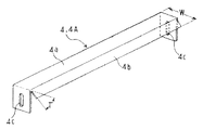
図5は、前記ガイド部材4,4Aの斜視図である。耐食性のある金属製薄板、例えばステンレス鋼の薄板等によりフラット面4aと傾斜面4bを形成し、高さ位置が調整できるように長穴4c,4cを穿設して取付けられるようにしてある。傾斜面4bの傾斜角度Tは、ガイド部材4の場合おおむね40〜45度、ガイド部材4Aの場合はおおむね15〜20度とするのが良い。幅Wは、ガイド部材4の場合、噴射ノズル7(図1)の洗浄水噴射幅に応じ、中間部の空きが確保されるようにして決め、ガイド部材4Aの場合はボックスカバー8,9の前方部と後方部の送りローラー1,1,…(図1)間の間隔に近接するような幅に決める。
FIG. 5 is a perspective view of the
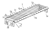
図6は、前記ガイド部材3の斜視図である。耐食性のある金属製の例えばステンレス鋼の小径丸棒材3a,3a,…を間隔Pが10〜25mmにして並べ、被洗浄物の移送前端をガイドする傾斜板3bを入口になる先端部に付設して支持棒3c,3cでバックアップ支持され、高さ位置が調整できるように取付板部に長穴3d,3d,…を穿設して取付けられるようにしてある。傾斜板3bの傾斜角度T1は、おおむね15〜20度、小径丸棒材3a,3a,…の直径dは、おおむね1.5〜3mmとし、回転ブラシ5(図1)でブラッシングする側の小径丸棒材の直径dは小径にして、間隔Pは広くするのが回転ブラシの羽毛先を通してブラッシングするのに抵抗が少なく好ましい。例えば回転ブラシ5でブラッシングする側の小径丸棒材の直径dを2mmにして間隔Pを25mmにし、すべりガイド側の小径丸棒材の直径dを3mmにして間隔Pを10mmにすると良い。
FIG. 6 is a perspective view of the
次に、回転ブラシによる被洗浄物のブラッシングと、噴射ノズルによる被洗浄物の洗浄例について図7,図8にて説明する。
図7は、回転ブラシ5により、被洗浄物Mの上面を上方からブラッシングする場合で、
(a)は要部側断面図、(b)は(a)のD−D断面図である。図示する如く、被洗浄物Mは、送りローラー1の外周上面と、押えローラー2の外周下面との間にスプリング19のスプリング力により挟み込まれるようにして送りローラー1の回転により、上下ガイド部材3,3の傾斜板3b,3bで被洗浄物の移送前端がガイドされて間隙Sへ移送されると共に、上方から回転ブラシ5の回転により被洗浄物の上面をブラッシングする。回転ブラシ5は、図7の(b)に示すように両端部が軸受22,22により支持された軸の一端を延出して自在接手23を介して支持板12の側部に取付けられた可変速モーター24に直結され、可変速モーター24により回転数が任意に変えてブラッシングできるようにしてある。上方のガイド部材3の小径丸棒材3a,3aは、下方のガイド部材3の小径丸棒材3aに較べ直径を小さくし、間隔を広くして回転ブラシ5の羽毛先を通してブラッシングするのに抵抗が少なくなるようにしてある。又、回転ブラシ5の回転方向は、被洗浄物Mの移送が妨げられない方向(本実施例図では矢印イ方向で、下方からブラッシングする場合は、矢印イ方向とは逆方向)とするのが良い。
Next, brushing of an object to be cleaned with a rotating brush and an example of cleaning of an object to be cleaned with a spray nozzle will be described with reference to FIGS.
FIG. 7 shows a case where the upper surface of the cleaning object M is brushed from above by the rotating brush 5.
(A) is principal part sectional side view, (b) is DD sectional drawing of (a). As shown in the figure, the upper and
図8は、高圧給水ポンプにより圧送された洗浄水を噴射ノズル7によりカーテン状に噴射させて被洗浄物Mの上面を洗浄する場合で、(a)の要部側断面図、(b)は(a)のE−E断面図である。前工程より移送された被洗浄物Mは、送りローラー1の外周上面と、押えローラー2の外周下面との間にスプリング19のスプリング力により挟み込まれるようにして送りローラー1の回転により、上方のガイド部材4,4と下方のガイド部材3の上方の傾斜部4b,4bと下方の傾斜板3bで被洗浄部Mの移送前端がガイドされて間隙Sへ移送され、送りローラー1,1間の前後にガイド部材4,4を取付けて中間部を空け、該空けた中間部に上方から噴射ノズル7,…よりカーテン状に洗浄水を噴射させることにより洗浄する。被洗浄物Mはガイド部材3の小径丸棒材3a,3aにより下方から下面が支えられて洗浄水の噴射圧を受けても撓わむことなく、且つ洗浄水が被洗浄物Mの小径孔をストレートに上方から下方へ貫通して洗浄され、小径丸棒材で被洗浄物Mの下面を受けてガイドするので洗浄水による面と面の付着がなくスムーズに被洗浄物は移送される。洗浄水の噴射圧は、図1に示した高圧給水ポンプ6からの給水配管の途中に設けられた調整バルブ7A,7Aにより任意に調整できるようにして、好適な噴射圧に調整できるようにしてある。
FIG. 8 shows a case where the cleaning water pumped by the high-pressure water supply pump is sprayed in the form of a curtain by the spray nozzle 7 to clean the upper surface of the object to be cleaned M. FIG. It is EE sectional drawing of (a). The object to be cleaned M transferred from the previous step is moved upward by rotation of the feed roller 1 so as to be sandwiched between the outer peripheral upper surface of the feed roller 1 and the outer peripheral lower surface of the
前記回転ブラシ5によるブラッシングと噴射ノズル7により洗浄水をカーテン状に噴射させて洗浄する部分、及びその前後の入口、出口部分においては、送りローラー1,1,…と、押えローラー2,2とにより被洗浄物Mを挟持するようにしてスムーズに移送させるためには送りローラー1,1の間隔を被洗浄物Mの送り幅と略一致するような間隔にするのが好ましく、前方の送りローラー1と押えローラーとで被洗浄物Mの前端部が挟持された時点で後方の送りローラー1と押えローラー2による被洗浄物Mの後端部が挟持からはずれるような間隔にするのが良い。
In the portion to be cleaned by spraying cleaning water in the form of a curtain with the brushing by the rotating brush 5 and the spray nozzle 7, and the inlet and outlet portions before and after that, the feed rollers 1, 1,. In order to smoothly move the object to be cleaned M so as to sandwich the object to be cleaned, it is preferable to set the interval between the feed rollers 1 and 1 to be substantially equal to the feed width of the object to be cleaned. It is preferable to set an interval so that the rear end portion of the object M to be cleaned by the rear feed roller 1 and the
前記図7、図8では被洗浄物Mの上面を上方から回転ブラシ5によりブラッシングし、噴射ノズル7により洗浄水を上方からカーテン状に噴射させて洗浄する洗浄例であるが、被洗浄物Mの下面は、回転ブラシ5と噴射ノズル7を下方に設けて、下方から前記同様に行う。そして被洗浄物Mの上面を上方から回転ブラシ5によりブラッシングし、洗浄水を上方から噴射ノズル7によりカーテン状に噴射させて洗浄した後、被洗浄物Mの下面を下方から回転ブラシ5によりブラッシングし、洗浄水を下方から噴射ノズル7によりカーテン状に噴射させて、被洗浄物の上面と下面を洗浄する。 FIGS. 7 and 8 are cleaning examples in which the upper surface of the object M to be cleaned is brushed from above by the rotating brush 5 and cleaning is performed by spraying the cleaning water in the form of a curtain from the upper side by the spray nozzle 7. The lower surface of is provided in the same manner as described above from below by providing the rotating brush 5 and the injection nozzle 7 below. Then, the upper surface of the object to be cleaned M is brushed from above by the rotating brush 5, and the cleaning water is sprayed from the upper side in the form of a curtain by the spray nozzle 7 for cleaning, and then the lower surface of the object to be cleaned M is brushed by the rotating brush 5 from below. Then, the cleaning water is sprayed in a curtain shape from below by the spray nozzle 7 to clean the upper surface and the lower surface of the object to be cleaned.
本発明は、えのき茸栽培用の巻板材以外の小径孔を多数穿設したシート等の薄板材にも利用の可能性がある。 The present invention may also be used for a thin plate material such as a sheet having a large number of small-diameter holes other than a wound plate material for enoki mushroom cultivation.
1 送りローラー
2 押えローラー
3,4,4A ガイド部材
3a 小径丸棒材
3b 傾斜板
3c 支持棒
3d,4c 長穴
4a フラット面
4b 傾斜面
5 回転ブラシ
6 高圧給水ポンプ
7 噴射ノズル
7A 調整バルブ
8,9 ボックスカバー
9a 排水管
9b 窓付き開閉扉
10 水切り台
11 架台
12 支持板
13,22 軸受
14 鎖歯車(スプロケット)
15,24 可変速モーター
16 モーター駆動チェーン
17 送りローラー駆動チェーン
18 支持ブラケット
19 スプリング
20 蝶番
21 天板
23 自在接手
M 被洗浄物(えのき茸栽培用巻板材)
DESCRIPTION OF SYMBOLS 1
15, 24 Variable speed motor 16 Motor drive chain 17 Feed
Claims (6)
Priority Applications (1)
| Application Number | Priority Date | Filing Date | Title |
|---|---|---|---|
| JP2005208554A JP4798427B2 (en) | 2005-07-19 | 2005-07-19 | Cleaning device and cleaning method for winding sheet material for enoki mushroom cultivation |
Applications Claiming Priority (1)
| Application Number | Priority Date | Filing Date | Title |
|---|---|---|---|
| JP2005208554A JP4798427B2 (en) | 2005-07-19 | 2005-07-19 | Cleaning device and cleaning method for winding sheet material for enoki mushroom cultivation |
Publications (2)
| Publication Number | Publication Date |
|---|---|
| JP2007020489A JP2007020489A (en) | 2007-02-01 |
| JP4798427B2 true JP4798427B2 (en) | 2011-10-19 |
Family
ID=37782086
Family Applications (1)
| Application Number | Title | Priority Date | Filing Date |
|---|---|---|---|
| JP2005208554A Expired - Fee Related JP4798427B2 (en) | 2005-07-19 | 2005-07-19 | Cleaning device and cleaning method for winding sheet material for enoki mushroom cultivation |
Country Status (1)
| Country | Link |
|---|---|
| JP (1) | JP4798427B2 (en) |
Families Citing this family (3)
| Publication number | Priority date | Publication date | Assignee | Title |
|---|---|---|---|---|
| CN102972203A (en) * | 2012-08-30 | 2013-03-20 | 上海雪榕生物科技股份有限公司 | Inoculation operation method for reducing contamination rate of cultivating bottle |
| CN102845226A (en) * | 2012-09-26 | 2013-01-02 | 济南蓬生农业科技有限公司 | Automatic water injection system for fungus bag |
| KR102134198B1 (en) * | 2018-08-08 | 2020-07-15 | 대한민국(농촌진흥청장) | Apparatus for cleaning wrapping film for mushroom |
Family Cites Families (6)
| Publication number | Priority date | Publication date | Assignee | Title |
|---|---|---|---|---|
| JP2566915B2 (en) * | 1986-02-10 | 1996-12-25 | 株式会社タツノ・メカトロニクス | Matsu Cleaner |
| JPH05317814A (en) * | 1992-03-31 | 1993-12-03 | Kazumi Noguchi | Cap cleaning device |
| JPH06154720A (en) * | 1992-11-19 | 1994-06-03 | Kususe Sangyo Kk | Mat washing machine |
| JP3346746B2 (en) * | 1999-02-15 | 2002-11-18 | 長野木田工業株式会社 | Mushroom cultivation roll cover and mushroom cultivation method using the same |
| JP2001051559A (en) * | 1999-08-12 | 2001-02-23 | Minolta Co Ltd | Sheet cleaning device |
| JP4602567B2 (en) * | 2000-12-15 | 2010-12-22 | 芝浦メカトロニクス株式会社 | Substrate cleaning device |
-
2005
- 2005-07-19 JP JP2005208554A patent/JP4798427B2/en not_active Expired - Fee Related
Also Published As
| Publication number | Publication date |
|---|---|
| JP2007020489A (en) | 2007-02-01 |
Similar Documents
| Publication | Publication Date | Title |
|---|---|---|
| US11370000B2 (en) | System for and method of by-product removal from a metal substrate | |
| US7727336B2 (en) | Glass washing machine with broken glass removal system | |
| US7419046B2 (en) | Method and device for washing conveyor belts | |
| JP4798427B2 (en) | Cleaning device and cleaning method for winding sheet material for enoki mushroom cultivation | |
| CN210907317U (en) | Vertical belt cleaning device of toughened glass | |
| US20050108847A1 (en) | Method and apparatus for cleaning sails | |
| JP4838929B2 (en) | Substrate processing equipment | |
| JP2003047448A (en) | Farm product washing/abrading apparatus | |
| JP6437735B2 (en) | Crop cleaning equipment | |
| CN114029273B (en) | Coating equipment is washd to intelligence | |
| JP3826966B2 (en) | Sheet cleaning device and sheet cleaning method | |
| JP4250122B2 (en) | Cleaning system | |
| JPH0838136A (en) | Continuous washer for root vegetables | |
| JP6325899B2 (en) | Hydroponic panel cleaning apparatus and method | |
| JP2006159120A (en) | Cleaning device | |
| JP2018038939A (en) | Bar cleaning device of bar conveyor | |
| CN114210649B (en) | Ultrasonic automatic cleaning device for sheet metal parts | |
| JPH0824553B2 (en) | Washing method and washing device for pickled vegetables | |
| JP4765775B2 (en) | Crop cleaning equipment | |
| CN219360619U (en) | Screen plate wiping mechanism | |
| JP3108711B1 (en) | Medal washing equipment | |
| JPS6340157Y2 (en) | ||
| JPH04247281A (en) | Surface treating device for plate body | |
| KR20060077746A (en) | Brushing unit of washing device for lcd panel | |
| JPH11138065A (en) | Work conveyance device for coating booth |
Legal Events
| Date | Code | Title | Description |
|---|---|---|---|
| A621 | Written request for application examination |
Free format text: JAPANESE INTERMEDIATE CODE: A621 Effective date: 20080714 |
|
| A977 | Report on retrieval |
Free format text: JAPANESE INTERMEDIATE CODE: A971007 Effective date: 20100805 |
|
| A131 | Notification of reasons for refusal |
Free format text: JAPANESE INTERMEDIATE CODE: A131 Effective date: 20101007 |
|
| RD04 | Notification of resignation of power of attorney |
Free format text: JAPANESE INTERMEDIATE CODE: A7424 Effective date: 20101013 |
|
| A521 | Written amendment |
Free format text: JAPANESE INTERMEDIATE CODE: A523 Effective date: 20101117 |
|
| TRDD | Decision of grant or rejection written | ||
| A01 | Written decision to grant a patent or to grant a registration (utility model) |
Free format text: JAPANESE INTERMEDIATE CODE: A01 Effective date: 20110705 |
|
| A01 | Written decision to grant a patent or to grant a registration (utility model) |
Free format text: JAPANESE INTERMEDIATE CODE: A01 |
|
| A61 | First payment of annual fees (during grant procedure) |
Free format text: JAPANESE INTERMEDIATE CODE: A61 Effective date: 20110720 |
|
| FPAY | Renewal fee payment (event date is renewal date of database) |
Free format text: PAYMENT UNTIL: 20170812 Year of fee payment: 6 |
|
| R150 | Certificate of patent or registration of utility model |
Free format text: JAPANESE INTERMEDIATE CODE: R150 |
|
| LAPS | Cancellation because of no payment of annual fees |