JP4796545B2 - Diagnostic tape cassette - Google Patents
Diagnostic tape cassette Download PDFInfo
- Publication number
- JP4796545B2 JP4796545B2 JP2007168251A JP2007168251A JP4796545B2 JP 4796545 B2 JP4796545 B2 JP 4796545B2 JP 2007168251 A JP2007168251 A JP 2007168251A JP 2007168251 A JP2007168251 A JP 2007168251A JP 4796545 B2 JP4796545 B2 JP 4796545B2
- Authority
- JP
- Japan
- Prior art keywords
- tape
- spring
- tape cassette
- housing
- test
- Prior art date
- Legal status (The legal status is an assumption and is not a legal conclusion. Google has not performed a legal analysis and makes no representation as to the accuracy of the status listed.)
- Active
Links
Images


Classifications
-
- B—PERFORMING OPERATIONS; TRANSPORTING
- B29—WORKING OF PLASTICS; WORKING OF SUBSTANCES IN A PLASTIC STATE IN GENERAL
- B29C—SHAPING OR JOINING OF PLASTICS; SHAPING OF MATERIAL IN A PLASTIC STATE, NOT OTHERWISE PROVIDED FOR; AFTER-TREATMENT OF THE SHAPED PRODUCTS, e.g. REPAIRING
- B29C45/00—Injection moulding, i.e. forcing the required volume of moulding material through a nozzle into a closed mould; Apparatus therefor
- B29C45/14—Injection moulding, i.e. forcing the required volume of moulding material through a nozzle into a closed mould; Apparatus therefor incorporating preformed parts or layers, e.g. injection moulding around inserts or for coating articles
- B29C45/14336—Coating a portion of the article, e.g. the edge of the article
- B29C45/14344—Moulding in or through a hole in the article, e.g. outsert moulding
-
- B—PERFORMING OPERATIONS; TRANSPORTING
- B29—WORKING OF PLASTICS; WORKING OF SUBSTANCES IN A PLASTIC STATE IN GENERAL
- B29C—SHAPING OR JOINING OF PLASTICS; SHAPING OF MATERIAL IN A PLASTIC STATE, NOT OTHERWISE PROVIDED FOR; AFTER-TREATMENT OF THE SHAPED PRODUCTS, e.g. REPAIRING
- B29C45/00—Injection moulding, i.e. forcing the required volume of moulding material through a nozzle into a closed mould; Apparatus therefor
- B29C45/14—Injection moulding, i.e. forcing the required volume of moulding material through a nozzle into a closed mould; Apparatus therefor incorporating preformed parts or layers, e.g. injection moulding around inserts or for coating articles
- B29C45/14065—Positioning or centering articles in the mould
-
- G—PHYSICS
- G01—MEASURING; TESTING
- G01N—INVESTIGATING OR ANALYSING MATERIALS BY DETERMINING THEIR CHEMICAL OR PHYSICAL PROPERTIES
- G01N33/00—Investigating or analysing materials by specific methods not covered by groups G01N1/00 - G01N31/00
- G01N33/48—Biological material, e.g. blood, urine; Haemocytometers
- G01N33/483—Physical analysis of biological material
- G01N33/487—Physical analysis of biological material of liquid biological material
- G01N33/4875—Details of handling test elements, e.g. dispensing or storage, not specific to a particular test method
- G01N33/48764—Test tape taken off a spool
-
- B—PERFORMING OPERATIONS; TRANSPORTING
- B29—WORKING OF PLASTICS; WORKING OF SUBSTANCES IN A PLASTIC STATE IN GENERAL
- B29C—SHAPING OR JOINING OF PLASTICS; SHAPING OF MATERIAL IN A PLASTIC STATE, NOT OTHERWISE PROVIDED FOR; AFTER-TREATMENT OF THE SHAPED PRODUCTS, e.g. REPAIRING
- B29C45/00—Injection moulding, i.e. forcing the required volume of moulding material through a nozzle into a closed mould; Apparatus therefor
- B29C45/14—Injection moulding, i.e. forcing the required volume of moulding material through a nozzle into a closed mould; Apparatus therefor incorporating preformed parts or layers, e.g. injection moulding around inserts or for coating articles
- B29C45/14778—Injection moulding, i.e. forcing the required volume of moulding material through a nozzle into a closed mould; Apparatus therefor incorporating preformed parts or layers, e.g. injection moulding around inserts or for coating articles the article consisting of a material with particular properties, e.g. porous, brittle
-
- B—PERFORMING OPERATIONS; TRANSPORTING
- B29—WORKING OF PLASTICS; WORKING OF SUBSTANCES IN A PLASTIC STATE IN GENERAL
- B29K—INDEXING SCHEME ASSOCIATED WITH SUBCLASSES B29B, B29C OR B29D, RELATING TO MOULDING MATERIALS OR TO MATERIALS FOR MOULDS, REINFORCEMENTS, FILLERS OR PREFORMED PARTS, e.g. INSERTS
- B29K2705/00—Use of metals, their alloys or their compounds, for preformed parts, e.g. for inserts
-
- Y—GENERAL TAGGING OF NEW TECHNOLOGICAL DEVELOPMENTS; GENERAL TAGGING OF CROSS-SECTIONAL TECHNOLOGIES SPANNING OVER SEVERAL SECTIONS OF THE IPC; TECHNICAL SUBJECTS COVERED BY FORMER USPC CROSS-REFERENCE ART COLLECTIONS [XRACs] AND DIGESTS
- Y10—TECHNICAL SUBJECTS COVERED BY FORMER USPC
- Y10T—TECHNICAL SUBJECTS COVERED BY FORMER US CLASSIFICATION
- Y10T436/00—Chemistry: analytical and immunological testing
- Y10T436/11—Automated chemical analysis
- Y10T436/110833—Utilizing a moving indicator strip or tape
-
- Y—GENERAL TAGGING OF NEW TECHNOLOGICAL DEVELOPMENTS; GENERAL TAGGING OF CROSS-SECTIONAL TECHNOLOGIES SPANNING OVER SEVERAL SECTIONS OF THE IPC; TECHNICAL SUBJECTS COVERED BY FORMER USPC CROSS-REFERENCE ART COLLECTIONS [XRACs] AND DIGESTS
- Y10—TECHNICAL SUBJECTS COVERED BY FORMER USPC
- Y10T—TECHNICAL SUBJECTS COVERED BY FORMER US CLASSIFICATION
- Y10T436/00—Chemistry: analytical and immunological testing
- Y10T436/12—Condition responsive control
Abstract
Description
本発明は、体液を調べるための多数の検査領域を備える検査テープと、検査テープを収容するためのハウジングとを備える、特に血糖検査のための診断用のテープカセットに関する。このようなテープカセットの製造方法も、本発明の対象である。 The present invention relates to a diagnostic tape cassette, particularly for blood glucose testing, comprising a test tape having a large number of test areas for examining body fluids and a housing for receiving the test tape. Such a method of manufacturing a tape cassette is also an object of the present invention.
糖尿病患者の自己診断のために、従来、実際にいくつかの検査ストリップが用いられており、このような検査ストリップは、試料(血液ないし組織液)中のブドウ糖含有量を可能な限り正確かつ確実に判定するために、わずかな量の試料が与えられた後に、測光式または電気化学式に調べられる。利用者の利便性を改善するために、テープカセット形態の検査テープを使って、多数回の検査を行うことがすでに提案されている。このようなテープカセットは、必要なすべての調査工程を自動的かつ迅速に実行できるようにするために、使い捨て部品としてコンパクトな携帯型装置へ挿入できるのが望ましい。このとき消費部品は信頼性が求められるので、高い要求事項が課せられる大量生産品であることに留意しなくてはならない。 In the past, several test strips have been used for self-diagnosis of diabetic patients, and such test strips ensure the glucose content in the sample (blood or tissue fluid) as accurately and reliably as possible. To determine, after a small amount of sample is given, it is examined photometrically or electrochemically. In order to improve user convenience, it has already been proposed to perform a number of tests using a test tape in the form of a tape cassette. Such a tape cassette is preferably insertable into a compact portable device as a disposable part in order to be able to carry out all necessary investigation steps automatically and quickly. At this time, it is necessary to keep in mind that the consumption parts are mass-produced products with high requirements because reliability is required.
以上を前提とする本発明の課題は、従来技術で提案されている使い捨て利用のためのテープカセットをさらに改良して、簡単な製造可能性で、高い保管安定性と使用安定性を実現することにある。 The object of the present invention based on the above is to further improve the tape cassette for disposable use proposed in the prior art, and to realize high storage stability and use stability with simple manufacturability. It is in.
この課題を解決するために、請求項1および18に記載された構成要件の組み合わせが提案される。本発明の有利な実施態様および発展例は、従属請求項に記載されている。
In order to solve this problem, a combination of the constituent features described in
本発明は、できる限り少ない個別の構成部品で、テープカセットの機能性を保証するという思想を前提としている。したがって本発明では、ハウジングは、アウトサート技術で金属支持体と成形プラスチックから構成されたアウトサート成形部品を有していることが提案される。アウトサート(成形)技術は、金属・プラスチック複合部品の低コストの製造を可能にするものであり、材料ブリッジとアンダーカットとが堅固な結合を保証する。診断用テープカセットの観点からは、このようにして、特別な目的のためにハウジングに統合される機能部材を金属支持体に設けることも可能であり、別個の構成部品を製作して取り扱う必要がない。単なるプラスチック部品で発生するような変形は、特に金属支持体のおかげで、在庫備蓄ないし装置使用期間が長く続いた場合であっても回避され、壁厚がわずかであっても高いハウジング強度が実現される。それにより、検査の高い収納密度で、コンパクトな設計形態を生産工学の面から容易に具体化することができる。 The present invention presupposes the idea of ensuring the functionality of a tape cassette with as few individual components as possible. Therefore, in the present invention, it is proposed that the housing has an outsert molded part composed of a metal support and a molded plastic by the outsert technique. Outsert (molding) technology enables low-cost manufacturing of metal / plastic composite parts, and material bridges and undercuts ensure a tight bond. From the point of view of the diagnostic tape cassette, in this way it is also possible to provide the metal support with functional members that are integrated into the housing for special purposes, and it is necessary to produce and handle separate components. Absent. Deformations that occur in mere plastic parts, especially thanks to the metal support, can be avoided even if stock storage or equipment usage lasts for a long time, and high housing strength is achieved even with a small wall thickness Is done. Thereby, it is possible to easily embody a compact design form from the viewpoint of production engineering with a high storage density for inspection.
特別に好適なカセット構成のために、アウトサート成形部品に統合される機能部材は、ばね部材、結合部材、および/または案内部材を含んでいるのが好ましい。 For specially preferred cassette configurations, the functional members integrated into the outsert molded part preferably include spring members, coupling members and / or guide members.
機能部材が、金属支持体に構成された少なくとも1つのばね部材を含んでいることによって、テープ走行機能の調節にかかわる格別な利点が得られる。そうすればばね部材を別途ハウジングに挿入する必要がなくなり、むしろ、1回の作業工程でアウトサート成形部品へ所望の位置に統合することができる。 By including at least one spring member configured on the metal support, the functional member provides a special advantage for adjusting the tape running function. This eliminates the need to separately insert the spring member into the housing, but rather, it can be integrated into the desired position in the outsert molded part in a single work step.
別の有利な実施形態は、薄くても支持能力のあるハウジング壁部を具体化できるように、金属支持体が薄板裁断片から予備成形されていることを意図している。 Another advantageous embodiment contemplates that the metal support is pre-formed from a sheet piece so that a thin but supportable housing wall can be implemented.
薄板裁断片の裁断片の一部は、弾性的に復帰可能なばね部材として曲げられているのが好ましい。この場合、検査テープに対する密封機能のために、板ばねの形態の機能部材が設けられていると格別に好ましい。 It is preferable that a part of the cut piece of the thin plate cut piece is bent as an elastically recoverable spring member. In this case, it is particularly preferable that a functional member in the form of a leaf spring is provided for the sealing function with respect to the inspection tape.
いっそうの簡素化は、板ばねが一方の自由端で、成形プラスチックからなる壁部により初期応力をかけられた位置で取外し可能に保持されており、場合により、最終組立の過程で初めて所定の機能位置へと動くことを意図している。 A further simplification is that the leaf spring is removably held at one of the free ends in a prestressed position by a wall made of molded plastic, and in some cases it may not be possible for a given function for the first time in the final assembly process. Intended to move into position.
テープリールをばね付勢するために、渦巻ばねの形態の機能部材が設けられているのも好ましい。この場合、渦巻ばねが金属支持体の平面に比べて低い位置にあり、ハウジング内部へ螺旋状に引き伸ばされていると好都合である。渦巻ばねが、成形プラスチックからなるカバーによって、外部からの作用に対してカバーされていることにより、汚れに対してハウジング内部空間を保護するための別の利点も得られる。 It is also preferred that a functional member in the form of a spiral spring is provided in order to bias the tape reel. In this case, it is advantageous if the spiral spring is in a lower position relative to the plane of the metal support and is spirally extended into the housing. Another advantage for protecting the housing interior space against dirt is obtained by the spiral spring being covered by a cover made of molded plastic against external effects.
ばね機能や位置決めの操作をできるようにするために、成形プラスチックがばね部材の領域に、ばね部材に作用するエジェクタおよび/またはセンタリングピンのための少なくとも1つの壁破断部を有していると好ましい。 Preferably, the molded plastic has at least one wall break for the ejector and / or centering pin acting on the spring member in the region of the spring member in order to be able to operate the spring function and positioning. .
さらに別の有利な実施形態は、機能部材がアウトサート成形部品のための少なくとも1つの定着部材を含んでいることを意図している。これは、金属支持体に屹立する支持フックが係止部材の形態のプラスチックで押出被覆されることによって、格別に容易に具体化することができる。 Yet another advantageous embodiment contemplates that the functional member includes at least one anchoring member for the outsert molded part. This can be realized particularly easily by a support hook standing on the metal support being extrusion coated with plastic in the form of a locking member.
機能部材が、2つのテープリールのあいだで搬送される検査テープのためのカバーを含んでいることによって、さらに別の有利なハウジング機能が得られる。カバーは、プラスチックで押出被覆された、好ましくはアンダーカットのある金属支持体のラグとして構成されているのが好ましい。 A further advantageous housing function is obtained by the fact that the functional member includes a cover for a test tape conveyed between two tape reels. The cover is preferably constructed as a lug of a metal support which is extrusion coated with plastic, preferably with an undercut.
できる限り少ない摩擦損失でテープ走行を保証するために、機能部材が、検査テープを摺動案内するためのテープ方向転換部を含んでいると好ましい。 In order to guarantee the tape running with as little friction loss as possible, it is preferable that the functional member includes a tape direction changing portion for slidingly guiding the inspection tape.
アウトサート成形部品は、テープカセットのためのハウジング部品、特にカセット蓋またはカセット本体を構成しているのが好ましい。 The outsert molded part preferably constitutes the housing part for the tape cassette, in particular the cassette lid or the cassette body.
冒頭に述べた課題は、方法の観点からは、金属支持体を有利には薄板裁断片として予備成形し、アウトサート技術の射出成形によって成形プラスチック部品を備え付け、こうして形成されたアウトサート成形部品にテープカセットのための機能部材を統合することによって解決される。 The problem mentioned at the outset is that, from a process point of view, the metal support is preferably pre-formed as a sheet-fed piece and is provided with a molded plastic part by injection molding of the outsert technique, so that the formed outsert molded part This is solved by integrating the functional members for the tape cassette.
次に、図面に模式的に示されている実施例を参照しながら、本発明について詳しく説明する。 Next, the present invention will be described in detail with reference to the embodiments schematically shown in the drawings.
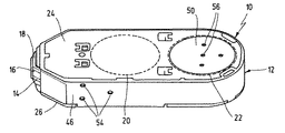
図面に示しているテープカセット10は、その場で患者自身により採取された血液試料を用いて、複数回のブドウ糖検査を実施することを可能にする。この目的のために、アプリケーション先端部18で連続的に血液を供給することができる多数の検査領域16が設けられた検査テープ14を収容するためのハウジング12が構成されている。このときテープ搬送は、ハウジング12に挿入された2つのテープリール20、22を介して行われる。原理的な検査手順は、たとえば国際公開第2004/056269号パンフレットに記載されており、ここで明文をもって同文献を援用する。
The
ハウジング12は、蓋部分として構成されたアウトサート成形部品24と、これと接合可能なカセット本体26とを含んでいる。アウトサート成形部品24は、図2に示す金属支持体28と、これに射出成形された図3に示すプラスチック30とで、アウトサート技術で作製されている。このようにして、さまざまな機能部品32を生産工学的、応用工学的に有利に完成部品へ統合することができる。アウトサート技術では、金属支持体28が、閉止可能な金型の成形キャビティへ挿入され、有利には射出成形によって、硬化可能なプラスチック素材で包囲される。このときプラスチックは、アンダーカットや破断部によって金属支持体に堅固に定着する。この方法それ自体は当業者には周知なので、これ以上の方法の詳細については、ここに記載する必要をみない。
The
図2は、打抜と折曲によって金属薄板裁断片34として形成された金属支持体28を示している。この裁断部品34は平坦な底面36を有しており、この底面から、さまざまな機能部品、特にばね部材38、40や支持部材42、44が折り曲げられている。
FIG. 2 shows a
面取りされた側面には、図示しないシール部を介してそばを通過する検査テープ14に対する改善された密閉機能のために、板ばね38が設けられている。巻取テープ22をばね力で付勢するために、底面36の領域には渦巻ばね40が配置されており、一体成形されたばね端部は円形に深絞りされており、自由なばね端部はハウジング内部に向って螺旋状に引き伸ばされている。
A
射出成形された定着部材を安定化させるために、複数の折曲された、アンダーカットのある側方の支持フック42が底面36に配分されて配置されている。底面36の縁部側には、側方の支持部材としてのラグ44が設けられている。
In order to stabilize the injection-molded fixing member, a plurality of bent
完成したアウトサート成形部品24は、図3では、ラグ44によって支持される側壁46を有しており、この側壁は、アプリケーション先端部18の領域を除き、検査テープ14を外方に向って覆っている。カセット本体26との係止のために、係止フック48が支持フック42の上にプラスチックで射出成形されている。渦巻ばね40は底面36の平面で、プラスチックでできた蓋50により外部から介入に対してカバーされている。この蓋は、底面36の内側にある向かい合う成形点52によって、金属支持体28と堅固に結合された状態に保たれる。
The completed outsert molded
射出成形金型の中で、板ばね38は隣接する側壁46の領域で初期応力をかけられ、硬化したプラスチックがその収縮挙動に基づいて保持機能を担うようになるまで、そこでセンタリングピンにより固定される。このときセンタリングピンは、図1の蓋部品24の外面に見られるように、プラスチックの破断部54を形成する。そして最終組立のときに、破断部54に挿通されたエジェクタによって、ばね38を内方に向って作用位置へ押し出すことができる。これに対応する破断部56は、渦巻ばね40のカバー50の領域にもある。
In the injection mold, the
カセット10の他の部品をアウトサート技術で構成することも、原則として可能である。特に、カセット本体26は、検査テープ14のためのテープ方向転換部が成形された金属支持体を有していてよい。このテープ方向転換部は、プラスチックで形成される本体部品が射出成形された後、外側で自由な状態に保たれ、それにより、リール20、22のあいだで先端部18を介して案内される検査テープは、金属のテープ方向転換部の上を少ない摩擦で摺動することになる。
It is also possible in principle to construct other parts of the
10 テープカセット
12 ハウジング
14 検査テープ
16 検査区域
22 リール
24 アウトサート成形部
26 カセット本体
28 金属支持体
30 成形プラスチック
36 機能部材
38 板ばね
40 渦巻ばね
42 支持フック
46、48、50 成形プラスチック部品(カバー)
DESCRIPTION OF
Claims (15)
前記アウトサート成形部品(24)は、前記金属支持体(28)の一部を構成するばね部材(40)を内面に備え、該ばね部材(40)が前記テープリール(22)をばね付勢することを特徴とするテープカセット。 An inspection tape (14) having a large number of inspection regions (16) for examining body fluid, a tape reel (22) for conveying the inspection tape, and the tape reel (22) are inserted, and the tape reel (22 And a housing (12) for housing a blood glucose test, particularly in a diagnostic tape cassette for blood glucose testing, the housing (12) is composed of a metal support (28) and a molded plastic (30). Having at least one outsert molded part (24) ;
The outsert molded part (24) includes a spring member (40) constituting a part of the metal support (28) on the inner surface, and the spring member (40) spring-biases the tape reel (22). A tape cassette characterized by
Applications Claiming Priority (2)
| Application Number | Priority Date | Filing Date | Title |
|---|---|---|---|
| EP06013199A EP1873521B1 (en) | 2006-06-27 | 2006-06-27 | Diagnostic test band cassette |
| EP06013199.2 | 2006-06-27 |
Publications (3)
| Publication Number | Publication Date |
|---|---|
| JP2008020444A JP2008020444A (en) | 2008-01-31 |
| JP2008020444A5 JP2008020444A5 (en) | 2009-02-19 |
| JP4796545B2 true JP4796545B2 (en) | 2011-10-19 |
Family
ID=37566099
Family Applications (1)
| Application Number | Title | Priority Date | Filing Date |
|---|---|---|---|
| JP2007168251A Active JP4796545B2 (en) | 2006-06-27 | 2007-06-26 | Diagnostic tape cassette |
Country Status (9)
| Country | Link |
|---|---|
| US (1) | US8003052B2 (en) |
| EP (1) | EP1873521B1 (en) |
| JP (1) | JP4796545B2 (en) |
| CN (1) | CN101097218B (en) |
| AT (1) | ATE525647T1 (en) |
| CA (1) | CA2592808C (en) |
| ES (1) | ES2372862T3 (en) |
| HK (1) | HK1116541A1 (en) |
| PL (1) | PL1873521T3 (en) |
Families Citing this family (9)
| Publication number | Priority date | Publication date | Assignee | Title |
|---|---|---|---|---|
| EP1873521B1 (en) * | 2006-06-27 | 2011-09-21 | F. Hoffmann-La Roche AG | Diagnostic test band cassette |
| EP1990001A1 (en) * | 2007-05-10 | 2008-11-12 | Roche Diagnostics GmbH | Piercing system and fleam conveyor |
| EP2078492A1 (en) * | 2008-01-11 | 2009-07-15 | Roche Diagnostics GmbH | Tape cassette for a medical hand device and blood sugar measuring system |
| EP2111786A1 (en) * | 2008-04-23 | 2009-10-28 | F. Hoffmann-Roche AG | Test system |
| US20170348479A1 (en) | 2016-06-03 | 2017-12-07 | Bryan Choate | Adhesive system for drug delivery device |
| CN106680264B (en) * | 2016-12-22 | 2019-10-18 | 安徽乐金环境科技有限公司 | Formaldehyde testing cassete |
| US11725741B2 (en) | 2018-07-17 | 2023-08-15 | Insulet Corporation | Low force valves for drug delivery pumps |
| DE102018132886B3 (en) | 2018-12-19 | 2019-12-12 | d&b audiotechnik Verwaltungs GmbH | Method for producing a plastic-coated loudspeaker housing and plastic-coated loudspeaker housing |
| FR3112983B1 (en) * | 2020-07-28 | 2022-12-23 | Fornells | Process for molding dark-colored recycled plastic parts associated by overmolding with another lighter-colored part |
Family Cites Families (46)
| Publication number | Priority date | Publication date | Assignee | Title |
|---|---|---|---|---|
| US3607099A (en) * | 1969-03-11 | 1971-09-21 | Medical Laboratory Automation | Prothrombin time measuring apparatus |
| US3728081A (en) * | 1971-07-08 | 1973-04-17 | Technicon Instr | Tape cartridge for use in automated sample analysis apparatus |
| US4158450A (en) * | 1976-07-30 | 1979-06-19 | Sony Corporation | Mounting of parts on a chassis or base plate |
| US4218421A (en) * | 1978-08-18 | 1980-08-19 | Honeywell Inc. | Disposable container for a continuous band of test strips |
| JPS57113449A (en) * | 1980-12-29 | 1982-07-14 | Sony Corp | Tape driver |
| NL8300730A (en) * | 1983-02-28 | 1984-09-17 | Philips Nv | MAGNETIC BAND TAPE DEVICE AND MAGNET HEAD UNIT APPLICABLE TO SUCH APPARATUS. |
| US4573011A (en) * | 1983-05-20 | 1986-02-25 | Nouvas Manufacturing Technology Company | Method and apparatus for testing electro-mechanical devices |
| JPH07122972B2 (en) * | 1987-01-27 | 1995-12-25 | ソニー株式会社 | Cassette reel |
| DE3816353A1 (en) * | 1988-05-13 | 1989-11-23 | Werner Stehr | MEASURING DEVICE WITH A MEASURING TAPE CASSETTE |
| JP2654682B2 (en) * | 1989-02-17 | 1997-09-17 | 富士写真フイルム株式会社 | Biochemical analyzer, biochemical analysis correction method and correction value recording medium |
| DE3911746A1 (en) * | 1989-04-11 | 1990-10-18 | Philips Patentverwaltung | TECHNICAL DEVICE, IN PARTICULAR ELECTROMECHANICAL DRIVE FOR MOVING INFORMATION CARRIERS, AND METHOD FOR PRODUCING FUNCTIONAL PARTS ON A SUPPORTING PLATE OF THE DEVICE |
| US5148350A (en) * | 1990-04-23 | 1992-09-15 | Motorola, Inc. | Portable electronics apparatus housing and chassis |
| US5232668A (en) * | 1991-02-27 | 1993-08-03 | Boehringer Mannheim Corporation | Test strip holding and reading mechanism for a meter |
| DE4236181A1 (en) * | 1992-10-27 | 1994-04-28 | Philips Patentverwaltung | Technical device, in particular electromechanical drive for moving information carriers |
| JP3108704B2 (en) * | 1993-08-05 | 2000-11-13 | 三菱電機株式会社 | Tape loading mechanism |
| DE4326339A1 (en) * | 1993-08-05 | 1995-02-09 | Boehringer Mannheim Gmbh | System for analysis of sample liquids |
| JPH0785645A (en) * | 1993-09-20 | 1995-03-31 | Sony Corp | Chassis structure for electronic apparatus |
| DE4339450A1 (en) * | 1993-11-19 | 1995-05-24 | Philips Patentverwaltung | Electromechanical mechanism for record medium, esp. car radio cassette |
| JP3467894B2 (en) * | 1995-03-07 | 2003-11-17 | ソニー株式会社 | Recording medium storage cassette |
| DE19635049A1 (en) * | 1996-08-30 | 1998-03-05 | Philips Patentverwaltung | Holding part molded from plastic |
| DE19715031A1 (en) * | 1997-04-11 | 1998-10-15 | Boehringer Mannheim Gmbh | Magazine for storing test elements |
| DE19811622A1 (en) * | 1998-03-17 | 1999-09-23 | Lre Technology Partner Gmbh | Laboratory instrument incorporating split test card housing |
| US7169355B1 (en) * | 2000-02-02 | 2007-01-30 | Applera Corporation | Apparatus and method for ejecting sample well trays |
| DE10047419A1 (en) * | 2000-09-26 | 2002-04-11 | Roche Diagnostics Gmbh | Lancet system |
| DE10105549A1 (en) * | 2001-02-06 | 2002-08-29 | Roche Diagnostics Gmbh | System for monitoring the concentration of analytes in body fluids |
| ES2269717T3 (en) * | 2001-06-08 | 2007-04-01 | Roche Diagnostics Gmbh | DEVICE OF EXTRACTION OF SAMPLES OF BODY FLUID AND CARTRIDGE WITH THE MEANS OF ANALYSIS TO BE USED WITH SUCH DEVICE. |
| US20030044318A1 (en) * | 2001-09-05 | 2003-03-06 | Lorin Olson | Devices for analyte concentration determination and methods of using the same |
| US6843899B2 (en) * | 2001-11-06 | 2005-01-18 | North Carolina State University | 2D/3D chemical sensors and methods of fabricating and operating the same |
| US20030211619A1 (en) * | 2002-05-09 | 2003-11-13 | Lorin Olson | Continuous strip of fluid sampling and testing devices and methods of making, packaging and using the same |
| US20040120861A1 (en) * | 2002-10-11 | 2004-06-24 | Affymetrix, Inc. | System and method for high-throughput processing of biological probe arrays |
| GB0227686D0 (en) * | 2002-11-27 | 2003-01-08 | City Tech | Gas sensing device |
| KR100699214B1 (en) * | 2002-12-23 | 2007-03-28 | 에프. 호프만-라 로슈 아게 | Body fluid testing device, test cassette, method of providing test medium, and method of analyzing body fluid |
| US7481777B2 (en) * | 2006-01-05 | 2009-01-27 | Roche Diagnostics Operations, Inc. | Lancet integrated test element tape dispenser |
| US7364699B2 (en) * | 2003-06-18 | 2008-04-29 | Bayer Healthcare Llc | Containers for reading and handling diagnostic reagents and methods of using the same |
| DE10332488A1 (en) * | 2003-07-16 | 2005-02-24 | Roche Diagnostics Gmbh | Analyzer and analysis method for body fluids |
| DE10338588A1 (en) * | 2003-08-22 | 2005-03-24 | Bayer Ag | Method for joining molded parts made of plastic and metal |
| DE10348283A1 (en) * | 2003-10-17 | 2005-05-12 | Roche Diagnostics Gmbh | Hand-held device for examining a body fluid |
| US7909776B2 (en) * | 2004-04-30 | 2011-03-22 | Roche Diagnostics Operations, Inc. | Lancets for bodily fluid sampling supplied on a tape |
| DE102004024970A1 (en) * | 2004-05-21 | 2005-12-08 | Roche Diagnostics Gmbh | Device and method for positioning a body part |
| US7455451B2 (en) * | 2005-03-11 | 2008-11-25 | The Colman Group, Inc. | Test strip dispenser and thermometer holder |
| DE102005013685A1 (en) * | 2005-03-18 | 2006-09-28 | Roche Diagnostics Gmbh | Tape magazine for a hand-held device for examining a body fluid, as well as a hand-held device |
| US7638095B2 (en) * | 2006-02-10 | 2009-12-29 | Roche Diagnostics Operations, Inc. | Personal portable blood glucose meter with replaceable cartridge of test strips |
| EP1852699A1 (en) * | 2006-05-06 | 2007-11-07 | F.Hoffmann-La Roche Ag | Diagnostic testing unit with container for test carriers |
| EP1873521B1 (en) * | 2006-06-27 | 2011-09-21 | F. Hoffmann-La Roche AG | Diagnostic test band cassette |
| DE502007006342D1 (en) * | 2006-08-22 | 2011-03-03 | Roche Diagnostics Gmbh | Diagnostic tape cassette, especially for blood glucose tests |
| ATE509576T1 (en) * | 2007-09-21 | 2011-06-15 | Hoffmann La Roche | STICKING SYSTEM AND TAPE CASSETTE |
-
2006
- 2006-06-27 EP EP06013199A patent/EP1873521B1/en active Active
- 2006-06-27 ES ES06013199T patent/ES2372862T3/en active Active
- 2006-06-27 AT AT06013199T patent/ATE525647T1/en active
- 2006-06-27 PL PL06013199T patent/PL1873521T3/en unknown
-
2007
- 2007-06-22 CA CA2592808A patent/CA2592808C/en active Active
- 2007-06-26 JP JP2007168251A patent/JP4796545B2/en active Active
- 2007-06-27 CN CN2007101095013A patent/CN101097218B/en active Active
- 2007-06-27 US US11/769,350 patent/US8003052B2/en active Active
-
2008
- 2008-06-20 HK HK08106898.2A patent/HK1116541A1/en unknown
Also Published As
| Publication number | Publication date |
|---|---|
| ES2372862T3 (en) | 2012-01-27 |
| PL1873521T3 (en) | 2012-02-29 |
| ATE525647T1 (en) | 2011-10-15 |
| HK1116541A1 (en) | 2008-12-24 |
| CA2592808A1 (en) | 2007-12-27 |
| CN101097218A (en) | 2008-01-02 |
| US8003052B2 (en) | 2011-08-23 |
| CN101097218B (en) | 2012-07-04 |
| EP1873521A1 (en) | 2008-01-02 |
| CA2592808C (en) | 2010-06-15 |
| US20080008989A1 (en) | 2008-01-10 |
| EP1873521B1 (en) | 2011-09-21 |
| JP2008020444A (en) | 2008-01-31 |
Similar Documents
| Publication | Publication Date | Title |
|---|---|---|
| JP4796545B2 (en) | Diagnostic tape cassette | |
| US7282055B2 (en) | Medical retrieval instrument | |
| US20200033337A1 (en) | Lateral flow assay with test strip retainer | |
| WO2016120919A1 (en) | Sensor insertion device and sensor insertion device set | |
| JP2021106936A (en) | Oxygen measuring device | |
| US9671387B2 (en) | Test system | |
| JP2008514949A (en) | Cassette assembly driving means and method | |
| US20060229651A1 (en) | Lancets | |
| KR20080012766A (en) | Treatment instrument for endoscope | |
| JP2008020444A5 (en) | ||
| JP2006514576A (en) | Leather blade platform and leather cartridge using the same | |
| JP2007537804A (en) | Apparatus and method for positioning a body part | |
| US9119579B2 (en) | Microdialysis probe and method for the production thereof | |
| JPWO2016120920A1 (en) | Sensor insertion device set and base plate | |
| WO2019176324A1 (en) | Sensor insertion device | |
| KR102134469B1 (en) | Core biopsy device | |
| US20210330178A1 (en) | Flexible endoscope with skeleton structure | |
| JP2006015143A (en) | Manufacturing device for packaging medical instrument including integrated lancet | |
| WO2019150621A1 (en) | Tip member of insertion device | |
| CN101305928A (en) | Digective canal tubular anastomat | |
| JP5945457B2 (en) | Endoscope tube and manufacturing method thereof | |
| KR102376214B1 (en) | Core biopsy device | |
| JP2005152620A (en) | Puncture device | |
| JP3502135B2 (en) | Medical device for intravascular insertion and method of manufacturing the same | |
| JP4639300B2 (en) | Lancet manufacturing method and lancet |
Legal Events
| Date | Code | Title | Description |
|---|---|---|---|
| A521 | Request for written amendment filed |
Free format text: JAPANESE INTERMEDIATE CODE: A523 Effective date: 20081226 |
|
| A621 | Written request for application examination |
Free format text: JAPANESE INTERMEDIATE CODE: A621 Effective date: 20081226 |
|
| RD03 | Notification of appointment of power of attorney |
Free format text: JAPANESE INTERMEDIATE CODE: A7423 Effective date: 20100525 |
|
| A131 | Notification of reasons for refusal |
Free format text: JAPANESE INTERMEDIATE CODE: A131 Effective date: 20110322 |
|
| A521 | Request for written amendment filed |
Free format text: JAPANESE INTERMEDIATE CODE: A523 Effective date: 20110617 |
|
| TRDD | Decision of grant or rejection written | ||
| A01 | Written decision to grant a patent or to grant a registration (utility model) |
Free format text: JAPANESE INTERMEDIATE CODE: A01 Effective date: 20110712 |
|
| A01 | Written decision to grant a patent or to grant a registration (utility model) |
Free format text: JAPANESE INTERMEDIATE CODE: A01 |
|
| A61 | First payment of annual fees (during grant procedure) |
Free format text: JAPANESE INTERMEDIATE CODE: A61 Effective date: 20110729 |
|
| R150 | Certificate of patent or registration of utility model |
Ref document number: 4796545 Country of ref document: JP Free format text: JAPANESE INTERMEDIATE CODE: R150 Free format text: JAPANESE INTERMEDIATE CODE: R150 |
|
| FPAY | Renewal fee payment (event date is renewal date of database) |
Free format text: PAYMENT UNTIL: 20140805 Year of fee payment: 3 |
|
| R250 | Receipt of annual fees |
Free format text: JAPANESE INTERMEDIATE CODE: R250 |
|
| R250 | Receipt of annual fees |
Free format text: JAPANESE INTERMEDIATE CODE: R250 |
|
| R250 | Receipt of annual fees |
Free format text: JAPANESE INTERMEDIATE CODE: R250 |
|
| R250 | Receipt of annual fees |
Free format text: JAPANESE INTERMEDIATE CODE: R250 |
|
| R250 | Receipt of annual fees |
Free format text: JAPANESE INTERMEDIATE CODE: R250 |
|
| R250 | Receipt of annual fees |
Free format text: JAPANESE INTERMEDIATE CODE: R250 |
|
| R250 | Receipt of annual fees |
Free format text: JAPANESE INTERMEDIATE CODE: R250 |
|
| R250 | Receipt of annual fees |
Free format text: JAPANESE INTERMEDIATE CODE: R250 |
|
| R250 | Receipt of annual fees |
Free format text: JAPANESE INTERMEDIATE CODE: R250 |
|
| R250 | Receipt of annual fees |
Free format text: JAPANESE INTERMEDIATE CODE: R250 |