JP4792177B2 - Zoom lens system - Google Patents
Zoom lens system Download PDFInfo
- Publication number
- JP4792177B2 JP4792177B2 JP2001207749A JP2001207749A JP4792177B2 JP 4792177 B2 JP4792177 B2 JP 4792177B2 JP 2001207749 A JP2001207749 A JP 2001207749A JP 2001207749 A JP2001207749 A JP 2001207749A JP 4792177 B2 JP4792177 B2 JP 4792177B2
- Authority
- JP
- Japan
- Prior art keywords
- zoom
- characteristic line
- lens
- focus lens
- zoom lens
- Prior art date
- Legal status (The legal status is an assumption and is not a legal conclusion. Google has not performed a legal analysis and makes no representation as to the accuracy of the status listed.)
- Expired - Fee Related
Links
Images
Landscapes
- Lens Barrels (AREA)
Description
【0001】
【発明の属する技術分野】
本発明は、ズームレンズシステムに関し、特にズームトラッキング制御を行うズームレンズシステムに関する。
【0002】
【従来の技術】
従来、ズーム機能を備えた一眼レフレックスカメラや電子ビュウファインダ内蔵のビデオカメラ等がある。これらのカメラにおいては、ズーミング中の、観察像のピントずれ、撮影画像のピントずれ、及びズームレンズとフォーカスレンズの衝突等を防止するため、ズーム動作に応じてフォーカスレンズを移動させる、いわゆるズームトラッキング制御が行われている。
【0003】
このズームトラッキング制御は、一般的に、ズーミング中のズームレンズ位置とフォーカスレンズ位置との関係を示す特性カーブ(特性線、トラッキングカーブ)に従いズームレンズ位置とフォーカスレンズ位置を移動制御するものであり、実際には、被写体距離に応じた複数の特性カーブを予めメモリに記憶させておき、ズーミング時の被写体距離に応じた所定の1つの特性カーブに従いワイド端(広角)からテレ端(望遠)までのズームレンズ位置とフォーカスレンズ位置の移動制御が行われている。
【0004】
このズームトラッキング制御の一例として、例えば特開平11−281869号公報には、特にズーミング中のズームレンズとフォーカスレンズの干渉を防ぐために、前述の特性カーブを備えて、ズーム動作の開始操作に連動して、まずフォーカスレンズをその特性カーブで定められる位置に移動させ、その後ズームレンズを動作させ、そのズーム動作の終了後にフォーカスレンズを移動させて合焦させるカメラが提案されている。
【0005】
【発明が解決しようとする課題】
ところで、上述の特性カーブは、最至近寄りの被写体距離に対応する特性カーブになるほどワイド端からテレ端までのフォーカスレンズ位置の可動範囲(繰り出し量)が大きくなることが知られている。そのため、マクロ撮影等のように最至近の被写体距離に対応する特性カーブに従いワイド端からテレ端までのフォーカスレンズ位置を移動制御するには、予めフォーカスレンズ位置の可動範囲を大きく取れるように鏡筒(レンズ鏡筒)を設計しなければならず、その場合は鏡筒が大型化するという問題があった。
【0006】
また、フォーカスレンズ位置の可動範囲を小さく設計すれば、鏡筒を小型化できるが、この場合には、最至近寄りの被写体距離に対応する特性カーブに従ったワイド端からテレ端までのフォーカスレンズ位置の移動制御、すなわちズームトラッキング制御を行えるズーム範囲が、最至近寄りの被写体距離の場合には制限されていた。
【0007】
本発明の課題は、上記実情に鑑み、鏡筒を小型化すると共に、ワイド側での合焦可能な被写体距離を出来る限り至近距離にし、かつワイド端からテレ端までズームトラッキング制御を可能にするズームレンズシステムを提供することである。
【0008】
本発明の第1の態様は、被写体距離に応じてズーミング時の光軸上のズームレンズ位置とフォーカスレンズ位置との関係を示す特性線であって、複数の被写体距離に対応する複数の特性線が予め記憶されており、該複数の特性線は、オートフォーカス手段により合焦されたときの被写体距離に応じた特性線に沿ってズーミング時のズームレンズ位置に対応するフォーカスレンズ位置を決定し、前記フォーカスレンズが可動範囲を超えないように前記特性線を乗り換えて合焦可能な最至近距離を変更するズームレンズ位置を不連続点として有するズームレンズシステムであって、ズームアップ時において前記不連続点を通過したか否かに応じて前記不連続点を通過したか否かを示す情報が記憶される記憶手段と、ズームアップ時において前記不連続点を通過した場合には、前記合焦可能な最至近の特性線上に乗り移るように制御すると共に、ズームダウン時において前記不連続点を通過したか否かを示す情報に基づいてズームアップ時と同じ軌跡をトレースするように制御する制御手段と、を有するズームレンズシステムである。
【0009】
上記の構成によれば、ズームアップ中に不連続点を通過したときには、合焦可能な最至近の特性線上に乗り移るように制御されるため、フォーカスレンズの可動(移動)範囲(繰り出し量)を小さく設計してレンズ鏡筒を小型化することができる。また、その不連続点を通過したか否かを示す情報を記憶しておくことにより、ズームダウン時には、その記憶した情報に基づき、ズームアップ時の軌跡と同様の軌跡を逆にトレースするように制御することが可能になる。
【0011】
本願発明の第2の態様は、上記第1の態様において、前記制御手段は、ズームダウン時、前記記憶手段に記憶された前記不連続点を通過したか否かを示す情報が前記不連続点を通過した旨の情報であるときは、前記不連続点までは前記合焦可能な最至近の特性線上を移動させ、それ以降は前記補間特性線上を移動させる制御を行う構成である。
【0012】
この構成によれば、ズームアップ時に不連続点を通過していたときには、その後のズームダウン時において、その不連続点まではズームレンズとフォーカスレンズを合焦可能な最至近の特性線に従い移動させ、それ以降は補間特性線に従い移動させることができる。
【0013】
本発明の第3の態様は、上記第1の態様において、前記制御手段は、ズームダウン時、前記記憶手段に記憶された前記不連続点を通過したか否かを示す情報が前記不連続点を通過していない旨の情報であるとき、ズームダウン開始が合焦可能な最至近の特性線上である場合は、合焦可能な最至近の特性線上を移動させ、ズームダウン開始が前記補間特性線上である場合は、前記補間特性線上を移動させる制御を行う構成である。
【0014】
この構成によれば、ズームアップ時に不連続点を通過していないときには、その後のズームダウン時において、ズームレンズとフォーカスレンズを合焦可能な最至近の特性線に従い移動させるか、又は補間特性線に従い移動させることができる。
【0015】
本発明の第4の態様は、上記第1の態様において、前記制御手段は、前記ズームアップ後に、撮影のためのレリーズスイッチが押されるまでは前記記憶手段に記憶された前記不連続点を通過したか否かを示す情報を保持し、前記レリーズスイッチが押されることにより前記記憶手段に記憶された前記不連続点を通過したか否かを示す情報をクリアする制御を行う構成である。
【0016】
この構成によれば、レリーズスイッチ(例えば1stレリーズスイッチ)が押されるまでは、不連続点を通過したか否かを示す情報が保持され、レリーズスイッチが押されると、その情報がクリアされる。すなわち、ピント合わせ(AF:自動焦点調節)が行われるまでは、その情報が保持され、ピント合わせが行われると、その情報がクリアされる。
【0017】
【発明の実施の形態】
以下、本発明の実施の形態を図面を参照しながら説明する。
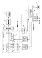
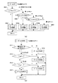
図1は、本発明の一実施の形態に係るズームレンズシステムとしての電子カメラの主要な構成を示すブロック図である。
【0018】
同図に示したように、電子カメラは、まず当該電子カメラ全体の制御、例えば後述するズームレンズ2、フォーカスレンズ3の制御を司るシステムコントローラ21を備える。尚、同図において特段に明示はしないが、システムコントローラ21は当該電子カメラ内の諸回路の制御を行うものとする。さらに当該電子カメラは電池24を内蔵しており、上記システムコントローラ21等、図示した回路のほか、図示しない諸回路への電源を供給するよう構成されている。
【0019】
また、当該電子カメラは、図示しない被写体像を入光してズーム及び合焦を行う撮影レンズ系1と、この撮影レンズ系1からの被写体像を受光し該被写体像に応じた電気信号に変換して出力する撮像素子11と、この撮像素子11からの被写体像信号にゲイン制御やサンプルホールド制御等の前処理を施す撮像回路12と、該撮像回路12において適宜処理された被写体像信号をA/D変換して出力するA/D変換回路13と、該A/D変換回路13でA/D変換された被写体像信号を入力しオートフォーカス演算を行いシステムコントローラ21に対して送出するAF回路16等を備えている。
【0020】
上記撮影レンズ系1は、第1群レンズ31と、第2群レンズ32及び第3群レンズ33からなるズームレンズ2と、第4群レンズたるフォーカスレンズ3等を備えている。ズームレンズ2はズームカム4を介してズームモータ5により、また、フォーカスレンズ3はフォーカスモータ6により駆動される。
【0021】
また、上記ズームモータ5、フォーカスモータ6は、システムコントローラ21の制御下にそれぞれズームモータ制御回路14、フォーカスモータ制御回路15によりその回動が制御される。同図において、符号4で示したズームカムは、図示しないカム枠に形成されたカム溝により構成され、ズームレンズ2の各レンズ群の移動に係わる。
【0022】
また、不図示であるが、第2群レンズ32と第3群レンズ33の間には、絞り及びシャッタが配置されており、システムコントローラ21による制御の基に、撮影レンズ系1内を通過する被写体光量の調節や被写体光の通過/遮断が行われる。
【0023】
一方、システムコントローラ21には、種々の操作スイッチ23が接続されているが、ここでは、本実施形態に深く係わるスイッチのみを説明する。
この操作スイッチ23には、テレ側(テレ端、望遠)へのズーム操作を行うテレズームスイッチ23aと、ワイド側(ワイド端、広角)へのズーム動作を行うワイドズームスイッチ23bと、レリーズスイッチ23c等を備えている。尚、不図示ではあるが、レリーズスイッチ23cは、さらに、ユーザがレリーズボタンを半押し状態にすることでONする1stレリーズスイッチと、それを全押し状態にすることでONする2ndレリーズスイッチの2つからなる。
【0024】
また、システムコントローラ21は、当該電子カメラの所定情報を記憶するメモリ22を内蔵している。このメモリ22には、後述する、不連続点を通過したか否かを示す情報(Flag1、Flag2)やAF(自動焦点調節)処理で得られた被写体距離(LD値)等が格納(記憶)される。また、システムコントローラ21の不図示の内部メモリには、当該電子カメラの各種制御プログラムや、被写体距離に応じてズーミング時の光軸上のズームレンズ位置とフォーカスレンズ位置との関係を示す複数の特性線(特性カーブ、トラッキングカーブ)に係るデータ等が記憶されている。本実施形態では、複数の特性線として、被写体距離が30cm、60cm、1.2m、無限遠に対応する4つの特性線に係るデータが記憶されている。尚、この特性線については後述する。
【0025】
また、システムコントローラ21は、フォーカスレンズ3を駆動するフォーカスモータ6(フォーカスモータ制御回路15)、及びズームレンズ2を駆動するズームモータ5(ズームモータ制御回路14)を制御し、ズームトラッキング制御の際には、AF回路16からの出力信号に基づき被写体距離(LD値)を求め、この被写体距離(LD値)に応じた上記特性線、又は複数の特性線に基づいて作成された補間特性線に従いズームレンズ2及びフォーカスレンズ3を移動すべく、ズームモータ5及びフォーカスモータ6を制御する。
【0026】
次に、上記第1群レンズ31、第2群レンズ32及び第3群レンズ33からなるズームレンズ2、及び第4群レンズたるフォーカスレンズ3の配置関係について説明する。
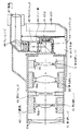
図2は、上記電子カメラの要部断面図である。
【0027】
同図に示したように、レンズ鏡筒40には、被写体側(同図左側)から、第1群レンズ31、第2群レンズ32及び第3群レンズ33からなるズームレンズ2、及び第4群レンズたるフォーカスレンズ3の順に各レンズ群が配置されている。
【0028】
第1群レンズ31はレンズ保持枠31aを介してレンズ鏡筒40に固定されている。
第2群レンズ32及び第3群レンズ33は、それぞれレンズ保持枠32a及び33aに保持されており、これら保持枠に設けられたピンを介していずれもカム枠内に形成されたカム溝(ズームカム4、図1参照)に係合する。すなわち、第2群レンズ32及び第3群レンズ33は、レンズ保持枠32a及び33aによりカム溝(ズームカム4)に係合し、カム枠の回動により前後方向に移動される。
【0029】
第4群レンズたるフォーカスレンズ3は、レンズ保持枠3aに保持されており、そのレンズ保持枠3aを介して、フォーカスモータ6の駆動により前後方向に移動される。本実施形態では、当該電子カメラを小型化するために、フォーカスレンズ3の可動(移動)範囲を小さく設計し、レンズ鏡筒40の小型化をはかっている。
【0030】
このように、第2群レンズ32、第3群レンズ33、及び第4群レンズたるフォーカスレンズ3は、いずれも、少なくとも前後方向において互いに独立して移動自在に構成されている。
また、レンズ鏡筒内には、更に絞り/シャッタ42が備えられている。絞りは、レンズ鏡筒40を通過する被写体光量を内部の複数枚の羽根の位置に応じて機械的に制御するものである。また、シャッタは、レンズ鏡筒40に入射した被写体光を通過又は遮断すべく羽根の位置で開閉するものである。
【0031】
また、電子カメラ本体41には、レンズ鏡筒内を通過した被写体光束を2方向に分光するビームスプリッタ43を備えており、そのビームスプリッタ43により分光された被写体光束の一方は、撮像素子(CCD)11に導かれ、他方は、ピント板44、アイピースシャッタ45、及びリレーレンズ46を介して接眼レンズ47へ導かれるように構成されている。また、電子カメラ本体41の背面には、撮影画像や各種メニュー等を表示可能なようにLCD48が設けられている。
【0032】
次に、システムコントローラ21の内部メモリに記憶されている特性線について説明する。
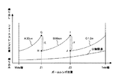
図3は、その内部メモリに記憶されている、被写体距離30cm、60cm、1.2m、無限遠に対応する4つの特性線を示す図である。
【0033】
同図において、横軸はワイド端(同図左側)からテレ端(同図右側)までのズームレンズ位置を示し、縦軸は繰り込み位置(同図下側)から繰り出し位置(同図上側)までのフォーカスレンズ位置を示している。
同図に示したように、特性線Aは、被写体距離30cmに対応する特性線であり、被写体距離30cmでズームレンズ位置がワイド端からZ1までの範囲で、その特性線Aに従いズームレンズ2とフォーカスレンズ3を移動制御することにより、ピントの合った状態でのズーミングが可能になる特性線である。また、特性線Bは、被写体距離60cmに対応する特性線であり、被写体距離60cmでズームレンズ位置がZ1からZ2までの範囲で、その特性線Bに従いズームレンズ2とフォーカスレンズ3を移動制御することにより、ピントの合った状態でのズーミングが可能になる特性線である。また、特性線Cは、被写体距離1.2mに対応する特性線であり、被写体距離1.2mでズームレンズ位置がZ2からテレ端までの範囲で、その特性線Cに従いズームレンズ2とフォーカスレンズ3を移動制御することにより、ピントの合った状態でのズーミングが可能になる特性線である。また、特性線Dは、被写体距離無限遠に対応する特性線であり、被写体距離無限遠のときに、その特性線Dに従いズームレンズ2とフォーカスレンズ3を移動制御することにより、ピントの合った状態でのズーミングが可能になる特性線である。
【0034】
また、本実施形態では、上記4つの特性線以外の特性線については、所定の2つの特性線の等比分割による補間処理により求めている。すなわち、ズームレンズ位置がワイド端からZ1までの範囲の補間特性線は、特性線Aと特性線Dに基づく補間により求めている。また、ズームレンズ位置がZ1からZ2までの範囲の補間特性線は、特性線Bと特性線Dに基づく補間により求めている。また、ズームレンズ位置がZ2からテレ端までの範囲の補間特性線は、特性線Cと特性線Dに基づく補間により求めている。
【0035】
また、本実施形態では、特性線A、特性線B、及び特性線Cの3つの特性線を1つの特性線として、これを合焦可能な最至近の特性線(以下、単に最至近の特性線と言う)と定義する。
また、前述したように、上記電子カメラでは、レンズ鏡筒40を小型化するため、フォーカスレンズ3の可動範囲(繰り出し量)を小さく設計している。従来では、このような設計の下でズームトラッキング制御を行うと、曲線を描く1つの特性線に従いワイド端からテレ端までの制御が行われていたために、フォーカスレンズがその可動範囲を超える問題があった。そこで、本実施形態では、所定のズームレンズ位置において、フォーカスレンズ3が所定のフォーカスレンズ位置に来たときに、制御の基となる特性線を変更し、フォーカスレンズ3が可動範囲を超えることのないように制御している。また、この所定のフォーカスレンズ位置は、ズームレンズ2とフォーカスレンズ3が干渉しないように考慮された位置でもある。この特性線を変更する(切り換える、乗り換える)位置を不連続点と定義する。すなわち、不連続点とは、焦点距離(ズームレンズ位置)に応じて合焦可能な最至近距離を変更するための点である。
【0036】
本実施形態では、ズームレンズ位置がZ1のときの、被写体距離が、30cm<被写体距離<60cmのときの対応する補間特性線上のフォーカスレンズ位置を一律に不連続点Eとしている。また、ズームレンズ位置がZ2のときの、被写体距離が、60cm<被写体距離<1.2mのときの対応する補間特性線上のフォーカスレンズ位置を一律に不連続点Fとしている。すなわち、ズームレンズ位置がZ1のときの、特性線A上の点Gと特性線B上の点Hとを結ぶ線分GH上であって、点G及び点Hを含まない全ての点が不連続点Eになりうる。また、ズームレンズ位置がZ2のときの、特性線B上の点Iと特性線C上の点Jとを結ぶ線分IJ上であって、点I及び点Jを含まない全ての点が不連続点Fになりうる。尚、述べるまでもないが、不連続点は、この不連続点Eや不連続点Fに限定されるものではなく、焦点距離に応じて合焦可能な最至近距離を変更するための点であれば、何れの点であっても良い。
【0037】
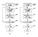
次に、上記電子カメラにおいて、システムコントローラ21によって行われる本発明に関係する各種の制御処理を、図4乃至図9に示すフローチャート及び図10を用いて説明する。尚、図4乃至図9に示す処理は、システムコントローラ21が、内部に備えられた制御プログラムを実行することにより行われる処理である。
【0038】
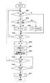
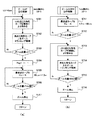
図4は、ズーム動作を伴う撮影処理の一例を示すフローチャートである。尚、同図に示したフローは、電子カメラの電源がONされ、フラグ(後述のFlag1、Flag2等)をクリアする等の初期化処理を行った後に開始される処理である。
【0039】
同図において、システムコントローラ21は、まず、テレズームスイッチ23a又はワイドズームスイッチ23bの何れかがONしているか否かを判断する(S401)。ここで、何れのスイッチもONしていなければ(S401がN)、S405の処理へスキップする。
【0040】
一方、何れかのズームスイッチがONしているときは(S401がY)、ONしているズームスイッチがテレズームスイッチ23aであるかワイドズームスイッチ23bであるかを判断する(S402)。ここで、テレズームスイッチ23aがONしているときは(S402がTele)、ズームアップ処理を行い(S403)、ワイドズームスイッチ23bがONしているときは(S402がWide)、ズームダウン処理を行う(S404)。
【0041】
尚、このズームアップ処理及びズームダウン処理については図5乃至図10を用いて詳述するが、例えば、ズームアップ処理では、システムコントローラ21の内部メモリに記憶されている上記4つの特性線とメモリ22に記憶されている被写体距離(LD値)に基づいて、ズームレンズ2及びフォーカスレンズ3の移動制御処理(ズームトラッキング制御処理)が行われる。このときの被写体距離(LD値)は、後述するS407の処理にてメモリ22に記憶されるものである。但し、電源がONされた直後にテレズームスイッチ23aがONされたときには、以前の電源ON時の最後にメモリ22に記憶された被写体距離(LD値)が使用されることになる。また、ズームアップ処理では、図3に示した不連続点E又は不連続点Fを通過したか否かに応じて、その不連続点E又は不連続点Fを通過したか否かを示す情報(Flag1、Flag2)が、メモリ22に記憶される。本実施形態では、不連続点Eを通過したときはFlag1=1になり、通過しなかったときはFlag1=0になる。また、不連続点Fを通過したときはFlag2=1になり、通過しなかったときはFlag2=0になる。
【0042】
このようなズームアップ処理又はズームダウン処理が終了すると、続いて、1stレリーズスイッチがONしているか否かを判断する(S405)。ここで、1stレリーズスイッチがONしていないときは(S405がN)、S401の処理へ戻る。一方、1stレリーズスイッチがONしているときは(S405がY)、AF(自動焦点調節)処理及びAE(自動露出)処理を行う(S406)。このAF処理では、AF回路16等を介して前述の被写体距離(LD値)が求められる。尚、このAF処理及びAE処理については周知の技術であるので、ここではその説明を省略する。
【0043】
続いて、そのAF処理で求めた被写体距離(LD値)をシステムコントローラ21のメモリ22に記憶し(S407)、システムコントローラ21のメモリ22に記憶されている不連続点E又は不連続点Fを通過したか否かを示す情報(Flag1、Flag2)をクリアする(S408)。すなわち、ズームアップ処理(S403)が行われた後から1stレリーズスイッチがONされるまでは、不連続点E又はFを通過したか否かを示す情報が保持され、1stレリーズスイッチがONされると、被写体距離(LD値)がメモリ22に記憶されると共に、不連続点E又は不連続点Fを通過したか否かを示す情報(Flag1、Flag2)がクリアされる。
【0044】
続いて、再び、1stレリーズスイッチがONしているか否かを判断し(S409)、ONしていなければ(S409がN)S401の処理へ戻る。
一方、1stレリーズスイッチがONしているときは(S409がY)、次に2ndレリーズスイッチがONしているか否かを判断する(S410)。ここで、2ndレリーズスイッチがONしていなければ(S410がN)S409の処理に戻り、ONしているときは(S410がY)、撮像素子11等を介して、撮影レンズ系1により撮像素子11に結像されている被写体像に応じた画像データを得る撮影処理を行い(S411)、当該フローを終了する。
【0045】
次に、上述した、ズームアップ処理(S403)及びズームダウン処理(S404)について説明する。
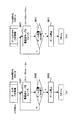
図5(a) は、ズームアップ処理(S403)の一例を示すフローチャート、同図(b) は、ズームダウン処理(S404)の一例を示すフローチャートである。尚、本実施形態では、説明の便宜のため、ズームアップ動作は、必ずワイド端からテレ端まで行われ、またズームダウン動作は、必ずテレ端からワイド端まで行われるものとする。
【0046】
図5(a) に示したように、ズームアップ処理では、メモリ22に記憶されている被写体距離(LD値)に応じて、4つのズームアップ処理の中から何れか1つの処理が決定され実行される。すなわち、被写体距離(LD値)が30cmのときは(S501がY)、後述するズームアップ▲1▼処理を行い(S502)リターンする。又は、被写体距離(LD値)が、30cm<被写体距離(LD値)≦60cmの範囲にあるときは(S503がY)、後述するズームアップ▲2▼処理を行い(S504)リターンする。又は、被写体距離(LD値)が、60cm<被写体距離(LD値)≦1.2mの範囲にあるときは(S505がY)、後述するズームアップ▲3▼処理を行い(S506)リターンする。又は、被写体距離(LD値)が、1.2mを超えるときは(S505がN)、後述するズームアップ▲4▼処理を行い(S507)リターンする。
【0047】
一方、図5(b) に示したように、ズームダウン処理では、テレ端でのフォーカスレンズ位置が最至近の特性線(ここでは特性線C)上にあるか否か、及びFlag1、Flag2の値に応じて、4つのズームダウン処理の中から何れか1つの処理が決定され実行される。すなわち、まず、テレ端でのフォーカスレンズ位置が最至近の特性線(最至近カーブ)上に存在するか否かを判断し(S511)、最至近の特性線上に存在しないときは(S511がN)、後述するズームダウン▲4▼処理を行い(S512)リターンする。
【0048】
一方、テレ端でのフォーカスレンズ位置が特性線C上に存在するときは(S511がY)、続いて、Flag2=1であるか否かを判断する(S513)。このFlag2は、ズームアップ処理において図3に示した不連続点Fを通過したか否かを示す情報(フラグ)である。この判断処理で、不連続点Fを通過したことを示すFlag2=1のときは(S513がY)、ズームダウン▲3▼処理を行い(S514)リターンする。
【0049】
一方、不連続点Fを通過していないことを示すFlag2=0のときは(S513がN)、続いて、Flag1=1であるか否かを判断する(S515)。このFlag1は、ズームアップ処理において、図3に示した不連続点Eを通過したか否かを示す情報(フラグ)である。この判断処理で、不連続点Eを通過したことを示すFlag1=1のときは(S515がY)、ズームダウン▲2▼処理を行い(S516)リターンする。一方、不連続点Eを通過していないことを示すFlag1=0のときは(S515がN)、ズームダウン▲1▼処理を行い(S517)、リターンする。
【0050】
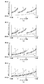
次に、上記ズームアップ▲1▼処理、ズームアップ▲2▼処理、ズームアップ▲3▼処理、ズームアップ▲4▼処理、及びズームダウン▲1▼処理、ズームダウン▲2▼処理、ズームダウン▲3▼処理、ズームダウン▲4▼処理について、図6乃至図9に示すフローチャート及び図10に示すワイド端(テレ端)からテレ端(ワイド端)までのフォーカスレンズ位置の軌跡、を用いて説明する。尚、図10では、その軌跡を太線で示している。
【0051】
まず、ズームアップ▲1▼処理とズームダウン▲1▼処理について説明する。
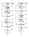
図6(a) はズームアップ▲1▼処理を示すフローチャート、同図(b) はズームダウン▲1▼処理を示すフローチャートである。また、図10(a) は、被写体距離(LD値)が30cmのときのワイド端(テレ端)からテレ端(ワイド端)までのフォーカスレンズ位置の軌跡を示した図である。
【0052】
図6(a) に示したように、ズームアップ▲1▼処理では、図10(a) の実線矢印に示したように、ワイド端からテレ端まで、最至近の特性線(最至近カーブ)に従い、ズームレンズ2及びフォーカスレンズ3を移動させる(S601)。すなわち、まず、ワイド端からZ1までは、特性線Aに従いズームレンズ2及びフォーカスレンズ3を移動させ、続くZ1からZ2までは、特性線Bに従いズームレンズ2及びフォーカスレンズ3を移動させ、続くZ2からテレ端までは、特性線Cに従いズームレンズ2及びフォーカスレンズ3を移動させる。また、このズームレンズ2とフォーカスレンズ3の移動中は、ズームレンズ2の単位移動毎に、ズームレンズ2がテレ端に到達したか否かの判断を行い(S602)、ズームレンズ2がテレ端に到達したら(S602がY)、ズームレンズ2及びフォーカスレンズ3の移動を停止し(S603)、当該フローをリターンする。
【0053】
このとき、ズームレンズ位置とフォーカスレンズ位置はテレ端の特性線C上にあり、また、Flag1及びFlag2は、不連続点E及び不連続点Fを通過していないので0である。従って、このような場合に行われるズームダウン処理では、図5(b) に示した処理により、ズームダウン▲1▼処理が行われる。
【0054】
図6(b) に示したように、ズームダウン▲1▼処理では、図10(a) の点線矢印に示したように、テレ端からワイド端まで、最至近の特性線(最至近カーブ)に従い、ズームレンズ2とフォーカスレンズ3を移動させる(S611)。すなわち、まず、テレ端からZ2までは、特性線Cに従いズームレンズ2及びフォーカスレンズ3を移動させ、続くZ2からZ1までは、特性線Bに従いズームレンズ2及びフォーカスレンズ3を移動させ、続くZ1からワイド端までは、特性線Aに従いズームレンズ2及びフォーカスレンズ3を移動させる。また、このズームレンズ2及びフォーカスレンズ3の移動中は、ズームレンズ2がワイド端に到達したか否かの判断を行い(S612)、ズームレンズ2がワイド端に到達したら(S612がY)、ズームレンズ2及びフォーカスレンズ3の移動を停止し(S613)、当該フローをリターンする。このように、ズームダウン▲1▼処理では、前述のズームアップ▲1▼処理における軌跡を逆にトレースするように、ズームレンズ2とフォーカスレンズ3が移動制御される。
【0055】
以上の図6(a),(b) に示した処理により、フォーカスレンズの可動範囲を小さく構成しながら、被写体距離(LD値)30cmにおけるズームトラッキング制御が可能になる。また、Z1とテレ端間の範囲においては、被写体距離(LD値)30cmに対応する特性線Aとは異なる特性線上を移動することになるので多少のピントずれが生じることになるが、接眼レンズでの確認に支障のない程度の許容されるレベルとすることも可能であり、ズーミング中に撮影が行われることもないので、特に問題にはならない。
【0056】
次に、ズームアップ▲2▼処理とズームダウン▲2▼処理について説明する。
図7(a) はズームアップ▲2▼処理を示すフローチャート、同図(b) はズームダウン▲2▼処理を示すフローチャートである。また、図10(b) は、被写体距離(LD値)が30cm<被写体距離(LD値)≦60cmの範囲にあるときの一例として、被写体距離(LD値)40cmのときのワイド端(テレ端)からテレ端(ワイド端)までのフォーカスレンズ位置の軌跡を示した図である。
【0057】
図7(a) に示したように、ズームアップ▲2▼処理では、図10(b) の実線矢印に示したように、まず、被写体距離(LD値)に対応する特性線がないため、ズームレンズ2の単位移動毎に、特性線Aと特性線Dに基づく補間により、その被写体距離(LD値)に対応するフォーカスレンズ位置を求め(S701)、その求めたフォーカスレンズ位置へフォーカスレンズ3を移動させる(S702)という処理を繰り返す。すなわち、ワイド端からZ1までは、特性線Aと特性線Dの補間により作成された補間特性線Kに従いズームレンズ2とフォーカスレンズ3が移動されることになる。また、このズームレンズ2とフォーカスレンズ3の移動中は、ズームレンズ2の単位移動毎に、ズームレンズ2がZ1に到着したか否かの判断を行い(S703)、ズームレンズ2がZ1に到着したら(S703がY)、すなわち不連続点Eに到着したら、その不連続点Eを通過した旨を示す情報としてFlag1を1にして(S704)、最至近の特性線に乗り移る。そして、続くZ1からテレ端までは、最至近の特性線(最至近カーブ)に従いズームレンズ2及びフォーカスレンズ3を移動させる(S705)。すなわち、Z1からZ2までは特性線Bに従いズームレンズ2及びフォーカスレンズ3を移動させ、続くZ2からテレ端までは、特性線Cに従いズームレンズ2及びフォーカスレンズ3を移動させる。また、このZ1からテレ端までは、ズームレンズ2の単位移動毎に、ズームレンズ2がテレ端に到達したか否かを判断し(S706)、ズームレンズ2がテレ端に到達したら(S706がY)、ズームレンズ2及びフォーカスレンズ3の移動を停止し(S707)、当該フローをリターンする。
【0058】
このとき、ズームレンズ位置とフォーカスレンズ位置はテレ端の特性線C上にある。また、不連続点Eを通過したのでFlag1は1であり、不連続点Fは通過していないのでFlag2は0である。従って、このような場合に行われるズームダウン処理では、図5(b) に示した処理により、ズームダウン▲2▼処理が行われる。
【0059】
図7(b) に示したように、ズームダウン▲2▼処理では、図10(b) の点線矢印に示したように、まず、テレ端からZ1までは、最至近の特性線(最至近カーブ)に従い、ズームレンズ2とフォーカスレンズ3を移動させる(S711)。すなわち、テレ端からZ2までは、特性線Cに従いズームレンズ2及びフォーカスレンズ3を移動させ、続くZ2からZ1までは、特性線Bに従いズームレンズ2及びフォーカスレンズ3を移動させる。また、このテレ端からZ1までは、ズームレンズ2の単位移動毎に、ズームレンズ2がZ1に到達したか否かを判断し(S712)、ズームレンズ2がZ1に到達したら(S712がY)、次のZ1以降は、ズームレンズ2の単位移動毎に、特性線Aと特性線Dに基づく補間により、その被写体距離(LD値)に対応するフォーカスレンズ位置を求め(S713)、その求めたフォーカスレンズ位置にフォーカスレンズ3を移動させる(S714)という処理を繰り返す。すなわち、Z1からワイド端までは、特性線Aと特性線Dの補間により作成された補間特性線Kに従いズームレンズ2とフォーカスレンズ3が移動されることになる。また、Z1からワイド端までのズームレンズ2とフォーカスレンズ3の移動中は、ズームレンズ2の単位移動毎に、ズームレンズ2がワイド端に到着したか否かの判断を行い(S715)、ズームレンズ2がZ1に到着したら(S715がY)、ズームレンズ2及びフォーカスレンズ3の移動を停止し(S716)、当該フローをリターンする。このように、ズームダウン▲2▼処理では、前述のズームアップ▲2▼処理によるズームレンズ2とフォーカスレンズ3の移動軌跡を逆にトレースするように、ズームレンズ2とフォーカスレンズ3が移動制御される。
【0060】
以上の図7(a),(b) に示した処理により、フォーカスレンズの可動範囲を小さく構成しながら、被写体距離が、30cm<被写体距離≦60cmの範囲におけるズームトラッキング制御が可能になる。また、同図(a),(b) に示した処理においても、Z1とテレ端間の範囲においては、被写体距離(LD値)に対応する特性線とは異なる特性線上を移動することになるので多少のピントずれが生じることになるが、接眼レンズでの確認に支障のない程度の許容されるレベルとすることも可能であり、ズーミング中に撮影が行われることもないので、特に問題にはならない。
【0061】
次に、ズームアップ▲3▼処理とズームダウン▲3▼処理について説明する。
図8(a) はズームアップ▲3▼処理を示すフローチャート、同図(b) はズームダウン▲3▼処理を示すフローチャートである。また、図10(c) は、被写体距離(LD値)が60cm<被写体距離(LD値)≦1.2mの範囲にあるときの一例として、被写体距離(LD値)70cmのときのワイド端(テレ端)からテレ端(ワイド端)までのフォーカスレンズ位置の軌跡を示した図である。
【0062】
図8(a) に示したように、ズームアップ▲3▼処理では、図10(c) の実線矢印に示したように、まず、被写体距離(LD値)に対応する特性線がないため、ワイド端からZ1までは、ズームレンズ2の単位移動毎に、特性線Aと特性線Dに基づく補間により、その被写体距離(LD値)に対応するフォーカスレンズ位置を求め、その求めたフォーカスレンズ位置にフォーカスレンズ3を移動させるという処理を繰り返し、続くZ1からZ2までは、ズームレンズ2の単位移動毎に、特性線Bと特性線Dに基づく補間により、その被写体距離(LD値)に対応するフォーカスレンズ位置を求め、その求めたフォーカスレンズ位置にフォーカスレンズ3を移動させるという処理を繰り返す(S801、S802)。すなわち、ワイド端からZ1までは特性線Aと特性線Dの補間により作成した補間特性線Lに従い、Z1からZ2までは特性線Bと特性線Dの補間により作成した補間特性線Mに従い、ズームレンズ2とフォーカスレンズ3が移動されることになる。また、ワイド端からZ2までの、ズームレンズ2とフォーカスレンズ3の移動中は、ズームレンズ2の単位移動毎に、ズームレンズ2がZ2に到着したか否かの判断を行い(S803)、ズームレンズ2がZ1に到着したら(S803がY)、すなわち不連続点Fに到着したら、その不連続点Fを通過した旨を示す情報としてFlag2を1にして(S804)、最至近の特性線(最至近カーブ)に乗り移る。そして、続くZ2からテレ端までは、最至近の特性線(最至近カーブ)に従いズームレンズ2及びフォーカスレンズ3を移動させる(S805)。すなわち、続くZ2からテレ端までは、特性線Cに従いズームレンズ2及びフォーカスレンズ3を移動させる。また、このZ2からテレ端までは、ズームレンズ2の単位移動毎に、ズームレンズ2がテレ端に到達したか否かを判断し(S806)、ズームレンズ2がテレ端に到達したら(S806がY)、ズームレンズ2及びフォーカスレンズ3の移動を停止し(S807)、当該フローをリターンする。
【0063】
このとき、ズームレンズ位置とフォーカスレンズ位置はテレ端の特性線C上にある。また、不連続点Eは通過していないのでFlag1は0であり、不連続点Fは通過したのでFlag2は1である。従って、このような場合に行われるズームダウン処理では、図5(b) に示した処理により、ズームダウン▲3▼処理が行われる。
【0064】
図8(b) に示したように、ズームダウン▲3▼処理では、図10(c) の点線矢印に示したように、まず、テレ端からZ2までは、最至近の特性線(最至近カーブ)に従いズームレンズ2及びフォーカスレンズ3を移動させる(S811)。すなわち、テレ端からZ2までは、特性線Cに従いズームレンズ2及びフォーカスレンズ3を移動させる。また、このテレ端からZ2までは、ズームレンズ2の単位移動毎に、ズームレンズ2がZ2に到達したか否かを判断し(S812)、ズームレンズ2がZ2に到達したら(S812がY)、次のZ2以降については、ズームレンズ2の単位移動毎に、Z2からZ1までは特性線Bと特性線Dに基づく補間により、その被写体距離(LD値)に対応するフォーカスレンズ位置を求め、その求めたフォーカスレンズ位置にフォーカスレンズ3を移動させるという処理を繰り返し、Z1からワイド端までは特性線Aと特性線Dに基づく補間により、その被写体距離(LD値)に対応するフォーカスレンズ位置を求め、その求めたフォーカスレンズ位置にフォーカスレンズ3を移動させるという処理を繰り返す(S813、S814)。すなわち、Z2からZ1までは特性線Bと特性線Dの補間により作成した補間特性線Mに従い、Z1からワイド端までは特性線Aと特性線Dの補間により作成した補間特性線Lに従い、ズームレンズ2とフォーカスレンズ3が移動されることになる。また、Z2からワイド端までの、ズームレンズ2とフォーカスレンズ3の移動中は、ズームレンズ2の単位移動毎に、ズームレンズ2がワイド端に到着したか否かの判断を行い(S815)、ズームレンズ2がワイド端に到着したら(S815がY)、ズームレンズ2及びフォーカスレンズ3の移動を停止し(S816)、当該フローをリターンする。このように、ズームダウン▲3▼処理では、前述のズームアップ▲3▼処理によるズームレンズ2とフォーカスレンズ3の移動軌跡を逆にトレースするように、ズームレンズ2とフォーカスレンズ3が移動制御される。
【0065】
以上の図8(a),(b) に示した処理により、フォーカスレンズの可動範囲を小さく構成しながら、被写体距離が、60cm<被写体距離≦1.2mの範囲におけるズームトラッキング制御が可能になる。また、同図(a),(b) に示した処理においても、Z2とテレ端間の範囲においては、被写体距離(LD値)に対応する特性線とは異なる特性線上を移動することになるので多少のピントずれが生じることになるが、接眼レンズでの確認に支障のない程度の許容されるレベルとすることも可能であり、ズーミング中に撮影が行われることもないので、特に問題にはならない。
【0066】
次に、ズームアップ▲4▼処理とズームダウン▲4▼処理について説明する。
図9(a) はズームアップ▲4▼処理を示すフローチャート、同図(b) はズームダウン▲4▼処理を示すフローチャートである。また、図10(d) は、被写体距離(LD値)が、1.2mを超えるときの一例として、被写体距離(LD値)1.2mのときのワイド端(テレ端)からテレ端(ワイド端)までのフォーカスレンズ位置の軌跡を示した図である。
【0067】
図9(a) に示したように、ズームアップ▲4▼処理では、図10(d) の実線矢印に示したように、まず、被写体距離(LD値)に対応する特性線がないため、ワイド端からZ1までは、ズームレンズ2の単位移動毎に、特性線Aと特性線Dに基づく補間により、その被写体距離(LD値)に対応するフォーカスレンズ位置を求め、その求めたフォーカスレンズ位置にフォーカスレンズ3を移動させるという処理を繰り返し、Z1からZ2までは、ズームレンズ2の単位移動毎に、特性線Bと特性線Dに基づく補間により、その被写体距離(LD値)に対応するフォーカスレンズ位置を求め、その求めたフォーカスレンズ位置にフォーカスレンズ3を移動させるという処理を繰り返し、Z2からテレ端までは、ズームレンズ2の単位移動毎に、特性線Cと特性線Dに基づく補間により、その被写体距離(LD値)に対応するフォーカスレンズ位置を求め、そのフォーカスレンズ位置にフォーカスレンズ3を移動させるという処理を繰り返す(S901、S902)。すなわち、ワイド端からZ1までは特性線Aと特性線Dの補間により作成した補間特性線Nに従い、Z1からZ2までは特性線Bと特性線Dの補間により作成した補間特性線Oに従い、Z2からテレ端までは特性線Cと特性線Dの補間により作成した補間特性線Pに従いズームレンズ2とフォーカスレンズ3が移動されることになる。また、ワイド端からテレ端までの、ズームレンズ2とフォーカスレンズ3の移動中は、ズームレンズ2の単位移動毎に、ズームレンズ2がテレ端に到着したか否かの判断を行い(S903)、ズームレンズ2がテレ端に到着したら(S903がY)、ズームレンズ2及びフォーカスレンズ3の移動を停止し(S904)、当該フローをリターンする。
【0068】
このとき、ズームレンズ位置とフォーカスレンズ位置はテレ端の特性線C上にはなく、また、不連続点E及び不連続点Fを通過していないので、Flag1、Flag2は0である。従って、このような場合に行われるズームダウン処理では、図5(b) に示した処理により、ズームダウン▲4▼処理が行われる。
【0069】
図9(b) に示したように、ズームダウン▲4▼処理では、図10(d) の点線矢印に示したように、テレ端からZ2までは、ズームレンズ2の単位移動毎に、特性線Cと特性線Dに基づく補間により、その被写体距離(LD値)に対応するフォーカスレンズ位置を求め、その求めたフォーカスレンズ位置にフォーカスレンズ3を移動させるという処理を繰り返し、Z2からZ1までは、ズームレンズ2の単位移動毎に、特性線Bと特性線Dに基づく補間により、その被写体距離(LD値)に対応するフォーカスレンズ位置を求め、その求めたフォーカスレンズ位置にフォーカスレンズ3を移動させるという処理を繰り返し、Z1からワイド端までは、ズームレンズ2の単位移動毎に、特性線Aと特性線Dに基づく補間により、その被写体距離(LD値)に対応するフォーカスレンズ位置を求め、その求めたフォーカスレンズ位置にフォーカスレンズ3を移動させるという処理を繰り返す(S911、S912)。すなわち、テレ端からZ2までは特性線Cと特性線Dの補間により作成した補間特性線Pに従い、Z2からZ1までは特性線Bと特性線Dの補間により作成した補間特性線Oに従い、Z1からワイド端までは特性線Aと特性線Dの補間により作成した補間特性線Nに従い、ズームレンズ2とフォーカスレンズ3が移動されることになる。また、テレ端からワイド端までの、ズームレンズ2とフォーカスレンズ3の移動中は、ズームレンズ2の単位移動毎に、ズームレンズ2がワイド端に到着したか否かの判断を行い(S913)、ズームレンズ2がワイド端に到着したら(S913がY)、ズームレンズ2及びフォーカスレンズ3の移動を停止し(S914)、当該フローをリターンする。このように、ズームダウン▲4▼処理では、前述のズームアップ▲4▼処理によるズームレンズ2とフォーカスレンズ3の移動軌跡を逆にトレースするように、ズームレンズ2とフォーカスレンズ3が移動制御される。
【0070】
以上の図9(a),(b) に示した処理により、フォーカスレンズの可動範囲を小さく構成しながら、被写体距離が、1.2mを超える範囲におけるズームトラッキング制御が可能になる。
尚、本実施形態では、本発明のズームレンズシステムを電子カメラに適用した形態を示したが、その他ズーム機能を備えた一眼レフレックスカメラや電子ビュウファインダ内蔵のビデオカメラ等、ズーム機能を備えてズームトラッキング制御を行う全ての機器に対して適用可能である。
【0071】
【発明の効果】
以上、詳細に説明したように、本発明によれば、鏡筒の小型化が可能になるばかりでなく、ワイド側での合焦可能な被写体距離を可能な限り至近距離に出来ると共に、ワイド端からテレ端までズームトラッキング制御が可能になる。
【図面の簡単な説明】
【図1】本発明の一実施の形態に係るズームレンズシステムとしての電子カメラの主要な構成を示すブロック図である。
【図2】電子カメラの要部断面図である。
【図3】被写体距離30cm、60cm、1.2m、無限遠に対応する4つの特性線を示す図である。
【図4】ズーム動作を伴う撮影処理の一例を示すフローチャートである。
【図5】 (a) はズームアップ処理の一例を示すフローチャート、(b) はズームダウン処理の一例を示すフローチャートである。
【図6】 (a) はズームアップ▲1▼処理を示すフローチャート、(b) はズームダウン▲1▼処理を示すフローチャートである。
【図7】 (a) はズームアップ▲2▼処理を示すフローチャート、(b) はズームダウン▲2▼処理を示すフローチャートである。
【図8】 (a) はズームアップ▲3▼処理を示すフローチャート、(b) はズームダウン▲3▼処理を示すフローチャートである。
【図9】 (a) はズームアップ▲4▼処理を示すフローチャート、(b) はズームダウン▲4▼処理を示すフローチャートである。
【図10】 (a) は被写体距離(LD値)が30cmのときのワイド端(テレ端)からテレ端(ワイド端)までのフォーカスレンズ位置の軌跡を示した図、(b) は被写体距離(LD値)が40cmのときのワイド端(テレ端)からテレ端(ワイド端)までのフォーカスレンズ位置の軌跡を示した図、(c) は被写体距離(LD値)が70cmのときのワイド端(テレ端)からテレ端(ワイド端)までのフォーカスレンズ位置の軌跡を示した図、(d) は被写体距離(LD値)が1.2mのときのワイド端(テレ端)からテレ端(ワイド端)までのフォーカスレンズ位置の軌跡を示した図である。
【符号の説明】
1 撮影レンズ系
2 ズームレンズ
3 フォーカスレンズ
3a 保持枠
4 ズームカム
5 ズームモータ
6 フォーカスモータ
11 撮像素子
12 撮像回路
13 A/D変換回路
14 ズームモータ制御回路
15 フォーカスモータ制御回路
21 システムコントローラ
22 メモリ
23 操作スイッチ
23a テレズームスイッチ
23b ワイドズームスイッチ
23c レリーズスイッチ
24 電池
31 第1群レンズ
31a 保持枠
32 第2群レンズ
32a 保持枠
33 第3群レンズ
33a 保持枠
40 レンズ鏡筒
41 カメラ本体
42 絞り/シャッタ
43 ビームスプリッタ
44 ピント板
45 アイピースシャッタ
46 リレーレンズ
47 接眼レンズ
48 LCD[0001]
BACKGROUND OF THE INVENTION
The present invention relates to a zoom lens system, and more particularly to a zoom lens system that performs zoom tracking control.
[0002]
[Prior art]
Conventionally, there are single-lens reflex cameras with a zoom function, video cameras with built-in electronic viewfinders, and the like. In these cameras, so-called zoom tracking that moves the focus lens according to the zoom operation is performed to prevent out-of-focus of the observed image, out-of-focus of the captured image, and collision between the zoom lens and the focus lens during zooming. Control is taking place.
[0003]
This zoom tracking control generally controls the movement of the zoom lens position and the focus lens position according to a characteristic curve (characteristic line, tracking curve) indicating the relationship between the zoom lens position during zooming and the focus lens position. Actually, a plurality of characteristic curves corresponding to the subject distance are stored in the memory in advance, and from a wide end (wide angle) to a tele end (telephoto) according to a predetermined one characteristic curve corresponding to the subject distance during zooming. Movement control of the zoom lens position and the focus lens position is performed.
[0004]
As an example of this zoom tracking control, for example, JP-A-11-28 1 Japanese Patent No. 869 discloses a position that is provided with the above-described characteristic curve in order to prevent interference between the zoom lens and the focus lens particularly during zooming, and the focus lens is first determined by the characteristic curve in conjunction with the start operation of the zoom operation. There has been proposed a camera in which the zoom lens is moved and then the zoom lens is operated, and the focus lens is moved and focused after the zoom operation is completed.
[0005]
[Problems to be solved by the invention]
By the way, it is known that the above-described characteristic curve has a larger movable range (advancing amount) of the focus lens position from the wide end to the tele end as the characteristic curve corresponds to the closest subject distance. Therefore, in order to move and control the focus lens position from the wide end to the tele end according to the characteristic curve corresponding to the closest subject distance, such as macro photography, the lens barrel is set so that the movable range of the focus lens position can be increased in advance. In this case, there is a problem that the lens barrel becomes large.
[0006]
Also, if the movable range of the focus lens position is designed to be small, the lens barrel can be reduced in size, but in this case, the focus lens from the wide end to the tele end according to the characteristic curve corresponding to the closest subject distance The zoom range in which position movement control, that is, zoom tracking control can be performed is limited when the subject distance is closest.
[0007]
In view of the above circumstances, the object of the present invention is to reduce the size of the lens barrel, make the subject distance that can be focused on the wide side as close as possible, and enable zoom tracking control from the wide end to the tele end. It is to provide a zoom lens system.
[0008]
First aspect of the present invention Indicates the relationship between the zoom lens position and the focus lens position on the optical axis during zooming according to the subject distance A characteristic line that corresponds to multiple subject distances Multiple characteristic lines in advance Remembered And The plurality of characteristic lines are: When zooming along the characteristic line according to the subject distance when focused by the autofocus means Corresponds to the zoom lens position Determine the focus lens position, Change the characteristic line so that the focus lens does not exceed the movable range. Change the closest distance that can be focused Zoom lens position A zoom lens system having discontinuous points, and storage means for storing information indicating whether or not the discontinuous points have been passed according to whether or not the discontinuous points have been passed during zooming up; When passing the discontinuous point during zoom-up Said At the time of zoom-up based on information indicating whether or not the discontinuous point has been passed during zoom-down while controlling to move to the closest characteristic line that can be focused Same as And a control unit that controls to trace the trajectory.
[0009]
According to the above configuration, when passing through a discontinuous point during zoom-up, control is performed so as to move to the closest characteristic line that can be focused, so that the movable (moving) range (feeding amount) of the focus lens is reduced. The lens barrel can be downsized by designing it small. In addition, by storing information indicating whether or not the discontinuous point has been stored, when zooming down, the same trajectory as that during zooming up is traced in reverse based on the stored information. It becomes possible to control.
[0011]
The second aspect of the present invention is , First aspect The control means, when zooming down, if the information indicating whether or not the discontinuous point stored in the storage means has passed the discontinuous point, the discontinuous point Up to the point Said Move on the closest characteristic line that can be focused, and then move on the interpolation characteristic line Do control It is a configuration.
[0012]
According to this configuration, when a discontinuous point is passed during zoom-up, the zoom lens and the focus lens are moved to the discontinuous point according to the closest characteristic line that can be focused during the subsequent zoom-down. After that, it can be moved according to the interpolation characteristic line.
[0013]
Third aspect of the present invention Is First aspect The control means is information indicating that the information indicating whether or not the discontinuous point stored in the storage means has not passed through the discontinuous point at the time of zooming down. When the zoom down start is on the closest characteristic line that can be focused, Move on the closest characteristic line that can be focused If the zoom-down start is on the interpolation characteristic line, Move on the interpolation characteristic line Do control It is a configuration.
[0014]
According to this configuration, when the zoom point does not pass through the discontinuous points, the zoom lens and the focus lens are moved according to the closest characteristic line that can be focused or the interpolation characteristic line at the subsequent zoom down. Can be moved according to
[0015]
Fourth aspect of the present invention Is First aspect The control means includes: After zooming up, Until the release switch for photographing is pushed, information indicating whether or not the discontinuous point stored in the storage means is held, and when the release switch is pushed, the information is recorded in the storage means. Memory Clear the information indicating whether the discontinuity point passed Do control It is a configuration.
[0016]
According to this configuration, the information indicating whether or not the discontinuous point has been passed is held until the release switch (for example, the 1st release switch) is pressed, and the information is cleared when the release switch is pressed. That is, the information is held until focusing (AF: automatic focus adjustment) is performed, and the information is cleared when focusing is performed.
[0017]
DETAILED DESCRIPTION OF THE INVENTION
Embodiments of the present invention will be described below with reference to the drawings.
FIG. 1 is a block diagram showing a main configuration of an electronic camera as a zoom lens system according to an embodiment of the present invention.
[0018]
As shown in the figure, the electronic camera includes a
[0019]
In addition, the electronic camera receives a subject image (not shown) to zoom and focus, and receives the subject image from the photographing
[0020]
The photographing
[0021]
The rotation of the
[0022]
Although not shown, a diaphragm and a shutter are disposed between the
[0023]
On the other hand, various operation switches 23 are connected to the
The operation switch 23 includes a
[0024]
The
[0025]
Further, the
[0026]
Next, the arrangement relationship of the zoom lens 2 including the
FIG. 2 is a cross-sectional view of a main part of the electronic camera.
[0027]
As shown in the figure, the lens barrel 40 includes a zoom lens 2 including a
[0028]
The
The
[0029]
The focus lens 3 as the fourth group lens is held by the lens holding frame 3a, and is moved in the front-rear direction by driving the focus motor 6 through the lens holding frame 3a. In this embodiment, in order to downsize the electronic camera, the movable (moving) range of the focus lens 3 is designed to be small, and the lens barrel 40 is downsized.
[0030]
Thus, the
An aperture / shutter 42 is further provided in the lens barrel. The diaphragm mechanically controls the amount of subject light passing through the lens barrel 40 according to the positions of a plurality of internal blades. The shutter opens and closes at the position of the blade so as to pass or block the subject light incident on the lens barrel 40.
[0031]
In addition, the electronic camera body 41 includes a beam splitter 43 that splits the subject light beam that has passed through the lens barrel in two directions, and one of the subject light beams separated by the beam splitter 43 is an image sensor (CCD). ) 11, and the other is configured to be guided to the eyepiece 47 through the focus plate 44, the eyepiece shutter 45, and the relay lens 46. In addition, an
[0032]
Next, the characteristic lines stored in the internal memory of the
FIG. 3 is a diagram showing four characteristic lines corresponding to subject distances of 30 cm, 60 cm, 1.2 m, and infinity stored in the internal memory.
[0033]
In this figure, the horizontal axis shows the zoom lens position from the wide end (left side in the figure) to the tele end (right side in the figure), and the vertical axis shows from the retracted position (lower side in the figure) to the extended position (upper side in the figure). The focus lens position is shown.
As shown in the figure, the characteristic line A is a characteristic line corresponding to a subject distance of 30 cm. When the subject distance is 30 cm and the zoom lens position is in the range from the wide end to Z1, This is a characteristic line that enables zooming in a focused state by controlling the movement of the focus lens 3. The characteristic line B is a characteristic line corresponding to a subject distance of 60 cm, and the zoom lens 2 and the focus lens 3 are moved and controlled according to the characteristic line B when the subject distance is 60 cm and the zoom lens position is in the range from Z1 to Z2. This is a characteristic line that enables zooming in a focused state. The characteristic line C is a characteristic line corresponding to a subject distance of 1.2 m, and the zoom lens 2 and the focus lens are in accordance with the characteristic line C in the range of the subject distance of 1.2 m and the zoom lens position from Z2 to the telephoto end. 3 is a characteristic line that enables zooming in a focused state by controlling the movement of 3. The characteristic line D is a characteristic line corresponding to an infinite subject distance. When the subject distance is infinite, the zoom lens 2 and the focus lens 3 are controlled to move in accordance with the characteristic line D, and the focus is achieved. This is a characteristic line that enables zooming in a state.
[0034]
Further, in the present embodiment, characteristic lines other than the above four characteristic lines are obtained by interpolation processing by equidivision division of two predetermined characteristic lines. In other words, the interpolation characteristic line whose zoom lens position is in the range from the wide end to Z1 is obtained by interpolation based on the characteristic line A and the characteristic line D. In addition, the interpolation characteristic line whose zoom lens position is in the range from Z1 to Z2 is obtained by interpolation based on the characteristic line B and the characteristic line D. The interpolation characteristic line in the range from the zoom lens position Z2 to the telephoto end is obtained by interpolation based on the characteristic line C and the characteristic line D.
[0035]
In the present embodiment, the three characteristic lines of the characteristic line A, the characteristic line B, and the characteristic line C are defined as one characteristic line, and the closest characteristic line that can be focused (hereinafter simply referred to as the closest characteristic line). Defined as a line).
Further, as described above, in the electronic camera, the movable range (feeding amount) of the focus lens 3 is designed to be small in order to reduce the size of the lens barrel 40. Conventionally, when zoom tracking control is performed under such a design, control from the wide end to the tele end is performed according to one characteristic line that draws a curve, and thus there is a problem that the focus lens exceeds the movable range. there were. Therefore, in the present embodiment, when the focus lens 3 comes to the predetermined focus lens position at the predetermined zoom lens position, the characteristic line that is the basis of control is changed, and the focus lens 3 exceeds the movable range. There is no control. The predetermined focus lens position is also a position that is considered so that the zoom lens 2 and the focus lens 3 do not interfere with each other. A position at which this characteristic line is changed (switched or switched) is defined as a discontinuous point. That is, the discontinuous point is a point for changing the closest distance that can be focused according to the focal length (zoom lens position).
[0036]
In the present embodiment, when the zoom lens position is Z1, the focus lens position on the corresponding interpolation characteristic line when the subject distance is 30 cm <subject distance <60 cm is uniformly set as the discontinuous point E. Further, when the zoom lens position is Z2, the focus lens position on the corresponding interpolation characteristic line when the subject distance is 60 cm <subject distance <1.2 m is uniformly set as the discontinuous point F. That is, when the zoom lens position is Z1, all points that are on the line segment GH connecting the point G on the characteristic line A and the point H on the characteristic line B and that do not include the point G and the point H are invalid. Can be a continuous point E. Further, when the zoom lens position is Z2, all the points on the line segment IJ connecting the point I on the characteristic line B and the point J on the characteristic line C that do not include the point I and the point J are invalid. Can be a continuous point F. Needless to say, the discontinuous point is not limited to the discontinuous point E or the discontinuous point F, but is a point for changing the closest distance that can be focused according to the focal length. Any point may be used.
[0037]
Next, various control processes related to the present invention performed by the
[0038]
FIG. 4 is a flowchart illustrating an example of a photographing process involving a zoom operation. The flow shown in the figure is a process that is started after the electronic camera is turned on and an initialization process such as clearing flags (Flag1, Flag2, etc. described later) is performed.
[0039]
In the figure, the
[0040]
On the other hand, when any one of the zoom switches is ON (S401: Y), it is determined whether the ON zoom switch is the
[0041]
This zoom-up process and zoom-down process will be described in detail with reference to FIGS. 5 to 10. For example, in the zoom-up process, the four characteristic lines and memory stored in the internal memory of the
[0042]
When such zoom-up processing or zoom-down processing is completed, it is subsequently determined whether or not the first release switch is ON (S405). If the first release switch is not ON (S405 is N), the process returns to S401. On the other hand, when the first release switch is ON (S405 is Y), AF (automatic focus adjustment) processing and AE (automatic exposure) processing are performed (S406). In this AF process, the above-mentioned subject distance (LD value) is obtained via the
[0043]
Subsequently, the subject distance (LD value) obtained by the AF process is stored in the
[0044]
Subsequently, it is determined again whether or not the first release switch is ON (S409). If it is not ON (S409 is N), the process returns to S401.
On the other hand, when the 1st release switch is ON (S409 is Y), it is next determined whether or not the 2nd release switch is ON (S410). Here, if the 2nd release switch is not turned on (N in S410), the process returns to S409. If it is turned on (Y in S410), the
[0045]
Next, the zoom-up process (S403) and zoom-down process (S404) described above will be described.
FIG. 5A is a flowchart showing an example of the zoom-up process (S403), and FIG. 5B is a flowchart showing an example of the zoom-down process (S404). In this embodiment, for convenience of explanation, it is assumed that the zoom-up operation is always performed from the wide end to the tele end, and the zoom-down operation is always performed from the tele end to the wide end.
[0046]
As shown in FIG. 5A, in the zoom-up process, one of the four zoom-up processes is determined and executed according to the subject distance (LD value) stored in the
[0047]
On the other hand, as shown in FIG. 5B, in the zoom-down process, whether or not the focus lens position at the telephoto end is on the closest characteristic line (here, characteristic line C) and whether Flag1 and Flag2 Depending on the value, any one of the four zoom-down processes is determined and executed. That is, first, it is determined whether or not the focus lens position at the telephoto end is on the closest characteristic line (closest curve) (S511). If it is not on the closest characteristic line (S511 is N). ), Zoom-down (4) described later is performed (S512), and the process returns.
[0048]
On the other hand, when the focus lens position at the telephoto end is present on the characteristic line C (S511 is Y), it is subsequently determined whether Flag2 = 1 (S513). This Flag2 is information (flag) indicating whether or not the discontinuous point F shown in FIG. In this determination process, when Flag2 = 1 indicating that the discontinuous point F has been passed (S513: Y), the zoom-down (3) process is performed (S514) and the process returns.
[0049]
On the other hand, when Flag2 = 0 indicating that the discontinuous point F has not been passed (S513: N), it is subsequently determined whether Flag1 = 1 (S515). This Flag1 is information (flag) indicating whether or not the discontinuous point E shown in FIG. If Flag1 = 1 indicating that the discontinuous point E has been passed in this determination processing (S515 is Y), zoom-down (2) processing is performed (S516), and the process returns. On the other hand, when Flag1 = 0 indicating that the discontinuous point E has not been passed (S515 is N), zoom-down (1) processing is performed (S517), and the process returns.
[0050]
Next, the zoom-up (1) processing, zoom-up (2) processing, zoom-up (3) processing, zoom-up (4) processing, and zoom-down (1) processing, zoom-down (2) processing, zoom-down ▲ 3) Processing and Zoom Down (4) Processing will be described using the flowcharts shown in FIGS. 6 to 9 and the locus of the focus lens position from the wide end (tele end) to the tele end (wide end) shown in FIG. To do. In FIG. 10, the locus is indicated by a bold line.
[0051]
First, zoom-up (1) processing and zoom-down (1) processing will be described.
FIG. 6 (a) is a flowchart showing zoom-up (1) processing, and FIG. 6 (b) is a flowchart showing zoom-down (1) processing. FIG. 10A shows the locus of the focus lens position from the wide end (tele end) to the tele end (wide end) when the subject distance (LD value) is 30 cm.
[0052]
As shown in FIG. 6 (a), in zoom-up (1) processing, as shown by the solid line arrow in FIG. 10 (a), the closest characteristic line (closest curve) from the wide end to the tele end is shown. Accordingly, the zoom lens 2 and the focus lens 3 are moved (S601). That is, first, from the wide end to Z1, the zoom lens 2 and the focus lens 3 are moved according to the characteristic line A, and from Z1 to Z2, the zoom lens 2 and the focus lens 3 are moved according to the characteristic line B, and then Z2 The zoom lens 2 and the focus lens 3 are moved according to the characteristic line C from the telephoto end to the telephoto end. Further, during the movement of the zoom lens 2 and the focus lens 3, it is determined whether or not the zoom lens 2 has reached the tele end every unit movement of the zoom lens 2 (S602). (S602 is Y), the movement of the zoom lens 2 and the focus lens 3 is stopped (S603), and the flow returns.
[0053]
At this time, the zoom lens position and the focus lens position are on the telephoto end characteristic line C, and Flag1 and Flag2 are 0 because they do not pass through the discontinuous point E and the discontinuous point F. Therefore, in the zoom-down process performed in such a case, the zoom-down process (1) is performed by the process shown in FIG.
[0054]
As shown in FIG. 6 (b), in the zoom-down (1) process, as shown by the dotted arrow in FIG. 10 (a), the closest characteristic line (closest curve) from the tele end to the wide end is shown. Accordingly, the zoom lens 2 and the focus lens 3 are moved (S611). That is, first, from the telephoto end to Z2, the zoom lens 2 and the focus lens 3 are moved according to the characteristic line C, and from Z2 to Z1, the zoom lens 2 and the focus lens 3 are moved according to the characteristic line B, and then Z1 The zoom lens 2 and the focus lens 3 are moved in accordance with the characteristic line A from the wide end to the wide end. While the zoom lens 2 and the focus lens 3 are moving, it is determined whether or not the zoom lens 2 has reached the wide end (S612). If the zoom lens 2 has reached the wide end (S612 is Y), The movement of the zoom lens 2 and the focus lens 3 is stopped (S613), and the flow returns. Thus, in the zoom-down (1) process, the movement of the zoom lens 2 and the focus lens 3 is controlled so that the locus in the zoom-up (1) process is traced in reverse.
[0055]
With the processing shown in FIGS. 6A and 6B, zoom tracking control can be performed at a subject distance (LD value) of 30 cm while the movable range of the focus lens is made small. Further, in the range between Z1 and the telephoto end, the lens moves on a characteristic line different from the characteristic line A corresponding to the subject distance (LD value) 30 cm. It is also possible to set the level to an acceptable level that does not hinder the confirmation in the camera, and since shooting is not performed during zooming, there is no particular problem.
[0056]
Next, zoom-up (2) processing and zoom-down (2) processing will be described.
FIG. 7A is a flowchart showing the zoom-up (2) process, and FIG. 7 (b) is a flowchart showing the zoom-down (2) process. FIG. 10B shows an example in which the subject distance (LD value) is in a range of 30 cm <subject distance (LD value) ≦ 60 cm, and the wide end (tele end) when the subject distance (LD value) is 40 cm. FIG. 6 is a diagram illustrating a locus of a focus lens position from a telephoto end to a tele end (wide end).
[0057]
As shown in FIG. 7A, in the zoom-up process (2), as shown by the solid line arrow in FIG. 10B, first, there is no characteristic line corresponding to the subject distance (LD value). For each unit movement of the zoom lens 2, a focus lens position corresponding to the subject distance (LD value) is obtained by interpolation based on the characteristic line A and the characteristic line D (S701), and the focus lens 3 is moved to the obtained focus lens position. The process of moving (S702) is repeated. That is, from the wide end to Z1, the zoom lens 2 and the focus lens 3 are moved according to the interpolation characteristic line K created by interpolation of the characteristic line A and the characteristic line D. While the zoom lens 2 and the focus lens 3 are moving, it is determined whether or not the zoom lens 2 has arrived at Z1 every unit movement of the zoom lens 2 (S703), and the zoom lens 2 arrives at Z1. Then (S703 is Y), that is, when arriving at the discontinuous point E, Flag1 is set to 1 as information indicating that the discontinuous point E is passed (S704), and the closest characteristic line is transferred. Then, from Z1 to the telephoto end, the zoom lens 2 and the focus lens 3 are moved according to the closest characteristic line (closest curve) (S705). That is, the zoom lens 2 and the focus lens 3 are moved according to the characteristic line B from Z1 to Z2, and the zoom lens 2 and the focus lens 3 are moved according to the characteristic line C from Z2 to the tele end. From Z1 to the tele end, it is determined whether or not the zoom lens 2 has reached the tele end for every unit movement of the zoom lens 2 (S706). If the zoom lens 2 has reached the tele end (S706 is determined). Y) The movement of the zoom lens 2 and the focus lens 3 is stopped (S707), and the flow returns.
[0058]
At this time, the zoom lens position and the focus lens position are on the characteristic line C at the telephoto end. Further, Flag1 is 1 because it has passed through the discontinuous point E, and Flag2 is 0 because it has not passed through the discontinuous point F. Accordingly, in the zoom-down process performed in such a case, the zoom-down process (2) is performed by the process shown in FIG.
[0059]
As shown in FIG. 7 (b), in the zoom-down (2) process, as shown by the dotted arrow in FIG. 10 (b), first, from the tele end to Z1, the closest characteristic line (closest The zoom lens 2 and the focus lens 3 are moved according to the curve (S711). That is, the zoom lens 2 and the focus lens 3 are moved according to the characteristic line C from the telephoto end to Z2, and the zoom lens 2 and the focus lens 3 are moved according to the characteristic line B from Z2 to Z1. From the telephoto end to Z1, it is determined whether or not the zoom lens 2 has reached Z1 every unit movement of the zoom lens 2 (S712), and when the zoom lens 2 has reached Z1 (Y in S712). After the next Z1, the focus lens position corresponding to the subject distance (LD value) is obtained by interpolation based on the characteristic line A and the characteristic line D for each unit movement of the zoom lens 2 (S713). The process of moving the focus lens 3 to the focus lens position (S714) is repeated. That is, from the Z1 to the wide end, the zoom lens 2 and the focus lens 3 are moved according to the interpolation characteristic line K created by the interpolation of the characteristic line A and the characteristic line D. Further, during the movement of the zoom lens 2 and the focus lens 3 from Z1 to the wide end, it is determined whether or not the zoom lens 2 has arrived at the wide end for every unit movement of the zoom lens 2 (S715). When the lens 2 arrives at Z1 (S715 is Y), the movement of the zoom lens 2 and the focus lens 3 is stopped (S716), and the flow returns. Thus, in the zoom-down process (2), the movement of the zoom lens 2 and the focus lens 3 is controlled so that the movement trajectories of the zoom lens 2 and the focus lens 3 by the zoom-up process (2) are reversed. The
[0060]
With the processing shown in FIGS. 7A and 7B, zoom tracking control can be performed in a range where the subject distance is 30 cm <subject distance ≦ 60 cm while the movable range of the focus lens is made small. Also, in the processing shown in FIGS. 4A and 4B, in the range between Z1 and the telephoto end, it moves on a characteristic line different from the characteristic line corresponding to the subject distance (LD value). As a result, a slight focus shift will occur, but it is possible to achieve an acceptable level that does not hinder the confirmation with the eyepiece, and shooting is not performed during zooming. Must not.
[0061]
Next, zoom-up (3) processing and zoom-down (3) processing will be described.
FIG. 8A is a flowchart showing zoom-up (3) processing, and FIG. 8 (b) is a flowchart showing zoom-down (3) processing. FIG. 10C shows an example in which the subject distance (LD value) is in the range of 60 cm <subject distance (LD value) ≦ 1.2 m. It is the figure which showed the locus | trajectory of the focus lens position from a tele end to a tele end (wide end).
[0062]
As shown in FIG. 8 (a), in the zoom-up process (3), as shown by the solid line arrow in FIG. 10 (c), there is no characteristic line corresponding to the subject distance (LD value). From the wide end to Z1, for each unit movement of the zoom lens 2, a focus lens position corresponding to the subject distance (LD value) is obtained by interpolation based on the characteristic line A and the characteristic line D, and the obtained focus lens position is obtained. The process of moving the focus lens 3 repeatedly is repeated, and the subsequent Z1 to Z2 correspond to the subject distance (LD value) by interpolation based on the characteristic line B and the characteristic line D for each unit movement of the zoom lens 2. The process of obtaining the focus lens position and moving the focus lens 3 to the obtained focus lens position is repeated (S801, S802). That is, zoom from the wide end to Z1 according to the interpolation characteristic line L created by the interpolation of the characteristic line A and the characteristic line D, and from Z1 to Z2 according to the interpolation characteristic line M created by the interpolation of the characteristic line B and the characteristic line D. The lens 2 and the focus lens 3 are moved. Further, during the movement of the zoom lens 2 and the focus lens 3 from the wide end to Z2, it is determined whether or not the zoom lens 2 has arrived at Z2 for each unit movement of the zoom lens 2 (S803). When the lens 2 arrives at Z1 (Y in S803), that is, arrives at the discontinuous point F, Flag2 is set to 1 as information indicating that the discontinuous point F has been passed (S804), and the closest characteristic line ( Change to the nearest curve. Then, the zoom lens 2 and the focus lens 3 are moved from Z2 to the telephoto end according to the closest characteristic line (closest curve) (S805). That is, the zoom lens 2 and the focus lens 3 are moved according to the characteristic line C from the subsequent Z2 to the telephoto end. From Z2 to the telephoto end, it is determined whether the zoom lens 2 has reached the telephoto end every unit movement of the zoom lens 2 (S806), and when the zoom lens 2 has reached the telephoto end (S806). Y) The movement of the zoom lens 2 and the focus lens 3 is stopped (S807), and the flow returns.
[0063]
At this time, the zoom lens position and the focus lens position are on the characteristic line C at the telephoto end. Since the discontinuous point E has not passed, Flag1 is 0, and since the discontinuous point F has passed, Flag2 is 1. Therefore, in the zoom-down process performed in such a case, the zoom-down process (3) is performed by the process shown in FIG.
[0064]
As shown in FIG. 8 (b), in the zoom-down (3) process, as shown by the dotted arrow in FIG. 10 (c), first, from the tele end to Z2, the closest characteristic line (closest The zoom lens 2 and the focus lens 3 are moved according to the curve (S811). That is, the zoom lens 2 and the focus lens 3 are moved according to the characteristic line C from the telephoto end to Z2. From the telephoto end to Z2, it is determined whether or not the zoom lens 2 has reached Z2 every unit movement of the zoom lens 2 (S812). If the zoom lens 2 has reached Z2 (Y in S812). For the subsequent Z2, the focus lens position corresponding to the subject distance (LD value) is obtained by interpolation based on the characteristic line B and the characteristic line D from Z2 to Z1 for each unit movement of the zoom lens 2. The process of moving the focus lens 3 to the determined focus lens position is repeated, and from Z1 to the wide end, the focus lens position corresponding to the subject distance (LD value) is obtained by interpolation based on the characteristic line A and the characteristic line D. The process of obtaining and moving the focus lens 3 to the obtained focus lens position is repeated (S813, S814). That is, zooming is performed according to the interpolation characteristic line M created by interpolation between the characteristic line B and the characteristic line D from Z2 to Z1, and according to the interpolation characteristic line L created by interpolation between the characteristic line A and the characteristic line D from Z1 to the wide end. The lens 2 and the focus lens 3 are moved. Further, during the movement of the zoom lens 2 and the focus lens 3 from Z2 to the wide end, it is determined whether or not the zoom lens 2 has arrived at the wide end for every unit movement of the zoom lens 2 (S815). When the zoom lens 2 arrives at the wide end (S815 is Y), the movement of the zoom lens 2 and the focus lens 3 is stopped (S816), and the flow returns. As described above, in the zoom-down (3) process, the zoom lens 2 and the focus lens 3 are controlled so as to reversely trace the movement locus of the zoom lens 2 and the focus lens 3 by the zoom-up (3) process described above. The
[0065]
With the processing shown in FIGS. 8A and 8B, zoom tracking control can be performed in a range where the subject distance is 60 cm <subject distance ≦ 1.2 m while the movable range of the focus lens is made small. . Also in the processing shown in FIGS. 4A and 4B, in the range between Z2 and the telephoto end, it moves on a characteristic line different from the characteristic line corresponding to the subject distance (LD value). As a result, a slight focus shift will occur, but it is possible to achieve an acceptable level that does not hinder the confirmation with the eyepiece, and shooting is not performed during zooming. Must not.
[0066]
Next, zoom-up (4) processing and zoom-down (4) processing will be described.
FIG. 9 (a) is a flowchart showing zoom-up (4) processing, and FIG. 9 (b) is a flowchart showing zoom-down (4) processing. FIG. 10D shows, as an example when the subject distance (LD value) exceeds 1.2 m, from the wide end (tele end) to the tele end (wide end) when the subject distance (LD value) is 1.2 m. It is the figure which showed the locus | trajectory of the focus lens position to (end).
[0067]
As shown in FIG. 9 (a), in the zoom-up process (4), as shown by the solid line arrow in FIG. 10 (d), there is no characteristic line corresponding to the subject distance (LD value). From the wide end to Z1, for each unit movement of the zoom lens 2, a focus lens position corresponding to the subject distance (LD value) is obtained by interpolation based on the characteristic line A and the characteristic line D, and the obtained focus lens position is obtained. The focus lens 3 is repeatedly moved. From Z1 to Z2, the focus corresponding to the subject distance (LD value) is obtained by interpolation based on the characteristic line B and the characteristic line D for each unit movement of the zoom lens 2. The process of obtaining the lens position and moving the focus lens 3 to the obtained focus lens position is repeated, and from Z2 to the telephoto end, every time the zoom lens 2 moves unit, By interpolation based on the line C and the characteristic line D, the determined focus lens position corresponding to an object distance (LD values), and repeats the process of moving the focus lens 3 in the focus lens position (S901, S902). That is, from the wide end to Z1, according to the interpolation characteristic line N created by interpolation of the characteristic line A and the characteristic line D, from Z1 to Z2 according to the interpolation characteristic line O created by interpolation of the characteristic line B and the characteristic line D, Z2 From the zoom lens 2 to the telephoto end, the zoom lens 2 and the focus lens 3 are moved according to the interpolation characteristic line P created by the interpolation of the characteristic line C and the characteristic line D. During the movement of the zoom lens 2 and the focus lens 3 from the wide end to the tele end, it is determined whether the zoom lens 2 has arrived at the tele end for every unit movement of the zoom lens 2 (S903). When the zoom lens 2 arrives at the tele end (Y in S903), the movement of the zoom lens 2 and the focus lens 3 is stopped (S904), and the flow returns.
[0068]
At this time, since the zoom lens position and the focus lens position are not on the characteristic line C at the tele end and do not pass through the discontinuous point E and the discontinuous point F, Flag1 and Flag2 are zero. Therefore, in the zoom-down process performed in such a case, the zoom-down process (4) is performed by the process shown in FIG.
[0069]
As shown in FIG. 9 (b), in the zoom-down (4) process, as shown by the dotted arrow in FIG. 10 (d), the characteristics from the telephoto end to Z2 are changed for each unit movement of the zoom lens 2. The process of obtaining the focus lens position corresponding to the subject distance (LD value) by interpolation based on the line C and the characteristic line D and moving the focus lens 3 to the obtained focus lens position is repeated, and from Z2 to Z1 For each unit movement of the zoom lens 2, the focus lens position corresponding to the subject distance (LD value) is obtained by interpolation based on the characteristic line B and the characteristic line D, and the focus lens 3 is moved to the obtained focus lens position. From Z1 to the wide end, the subject distance (L) is calculated by interpolation based on the characteristic line A and the characteristic line D for each unit movement of the zoom lens 2. Seeking a focus lens position corresponding to the value), and repeats the process of moving the focus lens 3 in the determined focus lens position (S911, S912). That is, from the telephoto end to Z2, Z1 follows the interpolation characteristic line P created by the interpolation of the characteristic line C and the characteristic line D, and from Z2 to Z1 follows the interpolation characteristic line O created by the interpolation of the characteristic line B and the characteristic line D. From the zoom lens 2 to the wide end, the zoom lens 2 and the focus lens 3 are moved according to the interpolation characteristic line N created by the interpolation of the characteristic line A and the characteristic line D. Further, during the movement of the zoom lens 2 and the focus lens 3 from the tele end to the wide end, it is determined whether or not the zoom lens 2 has reached the wide end for every unit movement of the zoom lens 2 (S913). When the zoom lens 2 arrives at the wide end (Y in S913), the movement of the zoom lens 2 and the focus lens 3 is stopped (S914), and the flow returns. As described above, in the zoom-down process (4), the movement of the zoom lens 2 and the focus lens 3 is controlled so that the movement trajectories of the zoom lens 2 and the focus lens 3 by the zoom-up process (4) are traced in reverse. The
[0070]
With the processing shown in FIGS. 9A and 9B, zoom tracking control can be performed in a range where the subject distance exceeds 1.2 m while the movable range of the focus lens is made small.
In this embodiment, the zoom lens system of the present invention is applied to an electronic camera. However, other embodiments such as a single-lens reflex camera having a zoom function and a video camera with a built-in electronic viewfinder have a zoom function. The present invention can be applied to all devices that perform zoom tracking control.
[0071]
【The invention's effect】
As described above in detail, according to the present invention, not only the lens barrel can be reduced in size, but also the subject distance that can be focused on the wide side can be as close as possible to the wide end, Zoom tracking control is possible from the telephoto end to the telephoto end.
[Brief description of the drawings]
FIG. 1 is a block diagram showing a main configuration of an electronic camera as a zoom lens system according to an embodiment of the present invention.
FIG. 2 is a cross-sectional view of a main part of the electronic camera.
FIG. 3 is a diagram illustrating four characteristic lines corresponding to subject distances of 30 cm, 60 cm, 1.2 m, and infinity.
FIG. 4 is a flowchart illustrating an example of a photographing process involving a zoom operation.
5A is a flowchart illustrating an example of zoom-up processing, and FIG. 5B is a flowchart illustrating an example of zoom-down processing.
6A is a flowchart showing zoom-up {circle around (1)} processing, and FIG. 6 (b) is a flowchart showing zoom-down {circle around (1)} processing.
7A is a flowchart showing zoom-up {circle around (2)} processing, and FIG. 7 (b) is a flowchart showing zoom-down {circle around (2)} processing.
FIG. 8A is a flowchart showing a zoom-up {circle around (3)} process, and FIG. 8 (b) is a flowchart showing a zoom-down {circle around (3)} process.
9A is a flowchart showing zoom-up {circle around (4)} processing, and FIG. 9 (b) is a flowchart showing zoom-down {circle around (4)} processing.
10A is a diagram showing a locus of a focus lens position from a wide end (tele end) to a tele end (wide end) when an object distance (LD value) is 30 cm, and FIG. 10B is an object distance. A diagram showing the locus of the focus lens position from the wide end (tele end) to the tele end (wide end) when (LD value) is 40 cm, (c) is the wide when the subject distance (LD value) is 70 cm. (D) shows the locus of the focus lens position from the end (tele end) to the tele end (wide end). (D) is the wide end (tele end) to the tele end when the subject distance (LD value) is 1.2 m. It is the figure which showed the locus | trajectory of the focus lens position to (wide end).
[Explanation of symbols]
1 Shooting lens system
2 Zoom lens
3 Focus lens
3a Holding frame
4 Zoom cam
5 Zoom motor
6 Focus motor
11 Image sensor
12 Imaging circuit
13 A / D conversion circuit
14 Zoom motor control circuit
15 Focus motor control circuit
21 System controller
22 memory
23 Operation switch
23a Tele zoom switch
23b Wide zoom switch
23c Release switch
24 batteries
31 First lens group
31a Holding frame
32 Second lens group
32a Holding frame
33 Third lens group
33a Holding frame
40 lens barrel
41 Camera body
42 Aperture / Shutter
43 Beam splitter
44 Focus board
45 Eyepiece shutter
46 Relay lens
47 Eyepiece
48 LCD
Claims (4)
ズームアップ時において前記不連続点を通過したか否かに応じて前記不連続点を通過したか否かを示す情報が記憶される記憶手段と、
ズームアップ時において前記不連続点を通過した場合には、前記合焦可能な最至近の特性線上に乗り移るように制御すると共に、ズームダウン時において前記不連続点を通過したか否かを示す情報に基づいてズームアップ時と同じ軌跡をトレースするように制御する制御手段と、
を有することを特徴とするズームレンズシステム。 A characteristic curve representing the relationship between the zoom lens position and the focus lens position on the optical axis during zooming according to the subject distance, a plurality of characteristic lines corresponding to the plurality of object distance is stored in advance, the A plurality of characteristic lines determine a focus lens position corresponding to a zoom lens position during zooming along a characteristic line corresponding to a subject distance when focused by the autofocus means, and the focus lens exceeds the movable range. A zoom lens system having as a discontinuous point a zoom lens position that changes the closest distance that can be focused by changing the characteristic line so as not to
Storage means for storing information indicating whether or not the discontinuous point has been passed according to whether or not the discontinuous point has been passed during zoom-up;
When passing through the discontinuous point during zoom-up, control is performed so as to get on the closest characteristic line that can be focused , and information indicating whether or not the discontinuous point has been passed during zoom-down Control means for controlling to trace the same locus as during zoom-up based on
A zoom lens system comprising:
ズームダウン時、前記記憶手段に記憶された前記不連続点を通過したか否かを示す情報が前記不連続点を通過した旨の情報であるときは、前記不連続点までは前記合焦可能な最至近の特性線上を移動させ、それ以降は前記補間特性線上を移動させる制御を行う、
ことを特徴とする請求項1に記載のズームレンズシステム。The control means includes
Zooming down when information indicating whether or not passing through the discontinuity point stored in said storage means is information indicating that passed through the discontinuity point, until the discontinuous point can the focusing To move on the closest characteristic line, and thereafter, control to move on the interpolation characteristic line,
The zoom lens system according to claim 1 .
ズームダウン時、前記記憶手段に記憶された前記不連続点を通過したか否かを示す情報が前記不連続点を通過していない旨の情報であるとき、ズームダウン開始が合焦可能な最至近の特性線上である場合は、合焦可能な最至近の特性線上を移動させ、ズームダウン開始が前記補間特性線上である場合は、前記補間特性線上を移動させる制御を行う、
ことを特徴とする請求項1記載のズームレンズシステム。The control means includes
Zooming down, the can with the information indicating whether or not passing through the discontinuity point stored in the storage means is information indicating that has not passed through the discontinuity point, zoom-start is possible focusing When it is on the closest characteristic line, it moves on the closest characteristic line that can be focused, and when the zoom down start is on the interpolation characteristic line, it performs control to move on the interpolation characteristic line.
The zoom lens system according to claim 1 .
前記ズームアップ後に、撮影のためのレリーズスイッチが押されるまでは前記記憶手段に記憶された前記不連続点を通過したか否かを示す情報を保持し、前記レリーズスイッチが押されることにより前記記憶手段に記憶された前記不連続点を通過したか否かを示す情報をクリアする制御を行う、
ことを特徴とする請求項1記載のズームレンズシステム。The control means includes
After the zoom-up, information indicating whether or not the discontinuous point has been stored in the storage means is held until the release switch for photographing is pressed, and the memory is stored when the release switch is pressed. It performs control for clearing the information indicating whether or not passing through the discontinuity point which is memorize the means,
The zoom lens system according to claim 1.
Priority Applications (1)
| Application Number | Priority Date | Filing Date | Title |
|---|---|---|---|
| JP2001207749A JP4792177B2 (en) | 2001-07-09 | 2001-07-09 | Zoom lens system |
Applications Claiming Priority (1)
| Application Number | Priority Date | Filing Date | Title |
|---|---|---|---|
| JP2001207749A JP4792177B2 (en) | 2001-07-09 | 2001-07-09 | Zoom lens system |
Publications (2)
| Publication Number | Publication Date |
|---|---|
| JP2003021777A JP2003021777A (en) | 2003-01-24 |
| JP4792177B2 true JP4792177B2 (en) | 2011-10-12 |
Family
ID=19043687
Family Applications (1)
| Application Number | Title | Priority Date | Filing Date |
|---|---|---|---|
| JP2001207749A Expired - Fee Related JP4792177B2 (en) | 2001-07-09 | 2001-07-09 | Zoom lens system |
Country Status (1)
| Country | Link |
|---|---|
| JP (1) | JP4792177B2 (en) |
Family Cites Families (7)
| Publication number | Priority date | Publication date | Assignee | Title |
|---|---|---|---|---|
| JPH0315012A (en) * | 1989-06-13 | 1991-01-23 | Minolta Camera Co Ltd | Camera |
| JPH07119881B2 (en) * | 1989-06-23 | 1995-12-20 | キヤノン株式会社 | Lens position control method |
| JP3387627B2 (en) * | 1994-04-28 | 2003-03-17 | キヤノン株式会社 | camera |
| JPH09101448A (en) * | 1995-10-06 | 1997-04-15 | Konica Corp | Power and focus adjustment controller |
| JP2000134526A (en) * | 1998-06-11 | 2000-05-12 | Konica Corp | Camera |
| JP4478230B2 (en) * | 1998-08-25 | 2010-06-09 | キヤノン株式会社 | FOCUS DETECTION DEVICE AND LENS POSITION CONTROL METHOD IN THE FOCUS DETECTION DEVICE |
| JP2001091815A (en) * | 1999-09-22 | 2001-04-06 | Fuji Photo Optical Co Ltd | Lens controller |
-
2001
- 2001-07-09 JP JP2001207749A patent/JP4792177B2/en not_active Expired - Fee Related
Also Published As
| Publication number | Publication date |
|---|---|
| JP2003021777A (en) | 2003-01-24 |
Similar Documents
| Publication | Publication Date | Title |
|---|---|---|
| JP5013078B2 (en) | Lens barrel and imaging device | |
| JP4035179B2 (en) | Photography lens and optical apparatus using the same | |
| KR101710633B1 (en) | Auto focus adjusting method, auto focus adjusting apparatus, and digital photographing apparatus including the same | |
| JP5623207B2 (en) | Imaging apparatus and control method thereof | |
| JP6525813B2 (en) | Imaging device, control method, program, and storage medium | |
| JP2007081473A (en) | Imaging apparatus having plural optical system | |
| CN112153276B (en) | Image pickup apparatus | |
| US5742435A (en) | Video-camera imaging-system zoom lens barrel | |
| JP2006093860A (en) | Camera mounted with twin lens image pick-up system | |
| JP2008294981A (en) | Camera system | |
| JP4500140B2 (en) | Camera equipped with a twin-lens imaging system | |
| JP4068716B2 (en) | Lens driving device and lens driving method for camera with zoom lens | |
| JP2013024900A (en) | Lens control device of optical apparatus | |
| JP4792177B2 (en) | Zoom lens system | |
| JP2010145495A (en) | Camera system | |
| JP5473565B2 (en) | Imaging device | |
| EP1591819B1 (en) | Drive controller of a lens system | |
| JP4239954B2 (en) | Camera device and focusing area control program | |
| JP2015118131A (en) | Imaging apparatus | |
| JP6104425B2 (en) | IMAGING DEVICE AND IMAGING DEVICE CONTROL METHOD | |
| JP2007078908A (en) | Lens device and focusing control method thereof | |
| JP2008107657A (en) | IMAGING DEVICE, ITS CONTROL METHOD, PROGRAM, AND STORAGE MEDIUM | |
| JP7581309B2 (en) | Control device, lens device, and imaging device | |
| JP4628015B2 (en) | AF control device for zoom lens | |
| JP2006093858A (en) | Camera mounted with twin lens image pick-up system |
Legal Events
| Date | Code | Title | Description |
|---|---|---|---|
| A621 | Written request for application examination |
Free format text: JAPANESE INTERMEDIATE CODE: A621 Effective date: 20080403 |
|
| A977 | Report on retrieval |
Free format text: JAPANESE INTERMEDIATE CODE: A971007 Effective date: 20101215 |
|
| A131 | Notification of reasons for refusal |
Free format text: JAPANESE INTERMEDIATE CODE: A131 Effective date: 20110118 |
|
| A521 | Written amendment |
Free format text: JAPANESE INTERMEDIATE CODE: A523 Effective date: 20110311 |
|
| TRDD | Decision of grant or rejection written | ||
| A01 | Written decision to grant a patent or to grant a registration (utility model) |
Free format text: JAPANESE INTERMEDIATE CODE: A01 Effective date: 20110719 |
|
| A01 | Written decision to grant a patent or to grant a registration (utility model) |
Free format text: JAPANESE INTERMEDIATE CODE: A01 |
|
| A61 | First payment of annual fees (during grant procedure) |
Free format text: JAPANESE INTERMEDIATE CODE: A61 Effective date: 20110725 |
|
| FPAY | Renewal fee payment (event date is renewal date of database) |
Free format text: PAYMENT UNTIL: 20140729 Year of fee payment: 3 |
|
| R151 | Written notification of patent or utility model registration |
Ref document number: 4792177 Country of ref document: JP Free format text: JAPANESE INTERMEDIATE CODE: R151 |
|
| S531 | Written request for registration of change of domicile |
Free format text: JAPANESE INTERMEDIATE CODE: R313531 |
|
| R350 | Written notification of registration of transfer |
Free format text: JAPANESE INTERMEDIATE CODE: R350 |
|
| LAPS | Cancellation because of no payment of annual fees |