JP4792176B2 - 骨スクリュー保持システム - Google Patents
骨スクリュー保持システム Download PDFInfo
- Publication number
- JP4792176B2 JP4792176B2 JP2001192408A JP2001192408A JP4792176B2 JP 4792176 B2 JP4792176 B2 JP 4792176B2 JP 2001192408 A JP2001192408 A JP 2001192408A JP 2001192408 A JP2001192408 A JP 2001192408A JP 4792176 B2 JP4792176 B2 JP 4792176B2
- Authority
- JP
- Japan
- Prior art keywords
- implant
- bone
- opening
- groove
- screw
- Prior art date
- Legal status (The legal status is an assumption and is not a legal conclusion. Google has not performed a legal analysis and makes no representation as to the accuracy of the status listed.)
- Expired - Fee Related
Links
- 210000000988 bone and bone Anatomy 0.000 title claims description 88
- 230000014759 maintenance of location Effects 0.000 title 1
- 239000007943 implant Substances 0.000 claims description 25
- 230000000295 complement effect Effects 0.000 claims description 10
- 238000000605 extraction Methods 0.000 description 11
- 238000003780 insertion Methods 0.000 description 6
- 230000037431 insertion Effects 0.000 description 6
- 239000000463 material Substances 0.000 description 6
- 238000004873 anchoring Methods 0.000 description 4
- 229910001069 Ti alloy Inorganic materials 0.000 description 2
- 230000008878 coupling Effects 0.000 description 2
- 238000010168 coupling process Methods 0.000 description 2
- 238000005859 coupling reaction Methods 0.000 description 2
- 238000010079 rubber tapping Methods 0.000 description 2
- RTAQQCXQSZGOHL-UHFFFAOYSA-N Titanium Chemical compound [Ti] RTAQQCXQSZGOHL-UHFFFAOYSA-N 0.000 description 1
- 239000004699 Ultra-high molecular weight polyethylene Substances 0.000 description 1
- 238000005553 drilling Methods 0.000 description 1
- 230000000694 effects Effects 0.000 description 1
- 238000002513 implantation Methods 0.000 description 1
- 238000000034 method Methods 0.000 description 1
- 239000007779 soft material Substances 0.000 description 1
- 238000011477 surgical intervention Methods 0.000 description 1
- 238000001356 surgical procedure Methods 0.000 description 1
- 210000001519 tissue Anatomy 0.000 description 1
- 229910052719 titanium Inorganic materials 0.000 description 1
- 239000010936 titanium Substances 0.000 description 1
- 229920000785 ultra high molecular weight polyethylene Polymers 0.000 description 1
- 239000011800 void material Substances 0.000 description 1
Images


Classifications
-
- A—HUMAN NECESSITIES
- A61—MEDICAL OR VETERINARY SCIENCE; HYGIENE
- A61B—DIAGNOSIS; SURGERY; IDENTIFICATION
- A61B17/00—Surgical instruments, devices or methods
- A61B17/56—Surgical instruments or methods for treatment of bones or joints; Devices specially adapted therefor
- A61B17/58—Surgical instruments or methods for treatment of bones or joints; Devices specially adapted therefor for osteosynthesis, e.g. bone plates, screws or setting implements
- A61B17/68—Internal fixation devices, including fasteners and spinal fixators, even if a part thereof projects from the skin
- A61B17/80—Cortical plates, i.e. bone plates; Instruments for holding or positioning cortical plates, or for compressing bones attached to cortical plates
- A61B17/8033—Cortical plates, i.e. bone plates; Instruments for holding or positioning cortical plates, or for compressing bones attached to cortical plates having indirect contact with screw heads, or having contact with screw heads maintained with the aid of additional components, e.g. nuts, wedges or head covers
- A61B17/8047—Cortical plates, i.e. bone plates; Instruments for holding or positioning cortical plates, or for compressing bones attached to cortical plates having indirect contact with screw heads, or having contact with screw heads maintained with the aid of additional components, e.g. nuts, wedges or head covers wherein the additional element surrounds the screw head in the plate hole
-
- A—HUMAN NECESSITIES
- A61—MEDICAL OR VETERINARY SCIENCE; HYGIENE
- A61B—DIAGNOSIS; SURGERY; IDENTIFICATION
- A61B17/00—Surgical instruments, devices or methods
- A61B17/56—Surgical instruments or methods for treatment of bones or joints; Devices specially adapted therefor
- A61B17/58—Surgical instruments or methods for treatment of bones or joints; Devices specially adapted therefor for osteosynthesis, e.g. bone plates, screws or setting implements
- A61B17/68—Internal fixation devices, including fasteners and spinal fixators, even if a part thereof projects from the skin
- A61B17/80—Cortical plates, i.e. bone plates; Instruments for holding or positioning cortical plates, or for compressing bones attached to cortical plates
- A61B17/8033—Cortical plates, i.e. bone plates; Instruments for holding or positioning cortical plates, or for compressing bones attached to cortical plates having indirect contact with screw heads, or having contact with screw heads maintained with the aid of additional components, e.g. nuts, wedges or head covers
- A61B17/8042—Cortical plates, i.e. bone plates; Instruments for holding or positioning cortical plates, or for compressing bones attached to cortical plates having indirect contact with screw heads, or having contact with screw heads maintained with the aid of additional components, e.g. nuts, wedges or head covers the additional component being a cover over the screw head
-
- A—HUMAN NECESSITIES
- A61—MEDICAL OR VETERINARY SCIENCE; HYGIENE
- A61B—DIAGNOSIS; SURGERY; IDENTIFICATION
- A61B17/00—Surgical instruments, devices or methods
- A61B17/56—Surgical instruments or methods for treatment of bones or joints; Devices specially adapted therefor
- A61B17/58—Surgical instruments or methods for treatment of bones or joints; Devices specially adapted therefor for osteosynthesis, e.g. bone plates, screws or setting implements
- A61B17/88—Osteosynthesis instruments; Methods or means for implanting or extracting internal or external fixation devices
- A61B17/8875—Screwdrivers, spanners or wrenches
-
- A—HUMAN NECESSITIES
- A61—MEDICAL OR VETERINARY SCIENCE; HYGIENE
- A61B—DIAGNOSIS; SURGERY; IDENTIFICATION
- A61B17/00—Surgical instruments, devices or methods
- A61B17/56—Surgical instruments or methods for treatment of bones or joints; Devices specially adapted therefor
- A61B17/58—Surgical instruments or methods for treatment of bones or joints; Devices specially adapted therefor for osteosynthesis, e.g. bone plates, screws or setting implements
- A61B17/88—Osteosynthesis instruments; Methods or means for implanting or extracting internal or external fixation devices
- A61B17/92—Impactors or extractors, e.g. for removing intramedullary devices
-
- A—HUMAN NECESSITIES
- A61—MEDICAL OR VETERINARY SCIENCE; HYGIENE
- A61B—DIAGNOSIS; SURGERY; IDENTIFICATION
- A61B17/00—Surgical instruments, devices or methods
- A61B17/56—Surgical instruments or methods for treatment of bones or joints; Devices specially adapted therefor
- A61B17/58—Surgical instruments or methods for treatment of bones or joints; Devices specially adapted therefor for osteosynthesis, e.g. bone plates, screws or setting implements
- A61B17/68—Internal fixation devices, including fasteners and spinal fixators, even if a part thereof projects from the skin
- A61B17/70—Spinal positioners or stabilisers, e.g. stabilisers comprising fluid filler in an implant
- A61B17/7059—Cortical plates
-
- A—HUMAN NECESSITIES
- A61—MEDICAL OR VETERINARY SCIENCE; HYGIENE
- A61B—DIAGNOSIS; SURGERY; IDENTIFICATION
- A61B17/00—Surgical instruments, devices or methods
- A61B17/56—Surgical instruments or methods for treatment of bones or joints; Devices specially adapted therefor
- A61B17/58—Surgical instruments or methods for treatment of bones or joints; Devices specially adapted therefor for osteosynthesis, e.g. bone plates, screws or setting implements
- A61B17/68—Internal fixation devices, including fasteners and spinal fixators, even if a part thereof projects from the skin
- A61B17/84—Fasteners therefor or fasteners being internal fixation devices
- A61B17/86—Pins or screws or threaded wires; nuts therefor
- A61B17/8625—Shanks, i.e. parts contacting bone tissue
- A61B17/8635—Tips of screws
-
- A—HUMAN NECESSITIES
- A61—MEDICAL OR VETERINARY SCIENCE; HYGIENE
- A61F—FILTERS IMPLANTABLE INTO BLOOD VESSELS; PROSTHESES; DEVICES PROVIDING PATENCY TO, OR PREVENTING COLLAPSING OF, TUBULAR STRUCTURES OF THE BODY, e.g. STENTS; ORTHOPAEDIC, NURSING OR CONTRACEPTIVE DEVICES; FOMENTATION; TREATMENT OR PROTECTION OF EYES OR EARS; BANDAGES, DRESSINGS OR ABSORBENT PADS; FIRST-AID KITS
- A61F2/00—Filters implantable into blood vessels; Prostheses, i.e. artificial substitutes or replacements for parts of the body; Appliances for connecting them with the body; Devices providing patency to, or preventing collapsing of, tubular structures of the body, e.g. stents
- A61F2/02—Prostheses implantable into the body
- A61F2/30—Joints
- A61F2002/30001—Additional features of subject-matter classified in A61F2/28, A61F2/30 and subgroups thereof
- A61F2002/30316—The prosthesis having different structural features at different locations within the same prosthesis; Connections between prosthetic parts; Special structural features of bone or joint prostheses not otherwise provided for
- A61F2002/30329—Connections or couplings between prosthetic parts, e.g. between modular parts; Connecting elements
- A61F2002/30476—Connections or couplings between prosthetic parts, e.g. between modular parts; Connecting elements locked by an additional locking mechanism
- A61F2002/30495—Connections or couplings between prosthetic parts, e.g. between modular parts; Connecting elements locked by an additional locking mechanism using a locking ring
-
- A—HUMAN NECESSITIES
- A61—MEDICAL OR VETERINARY SCIENCE; HYGIENE
- A61F—FILTERS IMPLANTABLE INTO BLOOD VESSELS; PROSTHESES; DEVICES PROVIDING PATENCY TO, OR PREVENTING COLLAPSING OF, TUBULAR STRUCTURES OF THE BODY, e.g. STENTS; ORTHOPAEDIC, NURSING OR CONTRACEPTIVE DEVICES; FOMENTATION; TREATMENT OR PROTECTION OF EYES OR EARS; BANDAGES, DRESSINGS OR ABSORBENT PADS; FIRST-AID KITS
- A61F2220/00—Fixations or connections for prostheses classified in groups A61F2/00 - A61F2/26 or A61F2/82 or A61F9/00 or A61F11/00 or subgroups thereof
- A61F2220/0025—Connections or couplings between prosthetic parts, e.g. between modular parts; Connecting elements
Landscapes
- Health & Medical Sciences (AREA)
- Orthopedic Medicine & Surgery (AREA)
- Life Sciences & Earth Sciences (AREA)
- Surgery (AREA)
- Medical Informatics (AREA)
- Engineering & Computer Science (AREA)
- Biomedical Technology (AREA)
- Heart & Thoracic Surgery (AREA)
- Nuclear Medicine, Radiotherapy & Molecular Imaging (AREA)
- Molecular Biology (AREA)
- Animal Behavior & Ethology (AREA)
- General Health & Medical Sciences (AREA)
- Public Health (AREA)
- Veterinary Medicine (AREA)
- Neurology (AREA)
- Surgical Instruments (AREA)
- Prostheses (AREA)
Description
【発明の属する技術分野】
本発明は、脊柱のための、骨接合装置に関し、装置は、プレート及び骨スクリュー又はアンカー要素を適所にロックするメカニズムを含む。
【0002】
【従来の技術】
米国特許第5876402号は、玉継手接続を形成するために、クリップ止めされる完全に球形のヘッドを備えた骨スクリューを収容できる円錐形の貫通穴を含む骨接合プレートに関する。穴の結合要素を補償する円錐形外部の二つ割連結要素が、提供される。止め輪は、貫通穴の口径を減じる。同様のクリップ及び溝配置が米国特許第5879389号及び第6102952号に示される。
【0003】
米国特許第5876402号では、骨スクリューは、プレートへ挿入前に連結要素内に置かれる。挿入に際して、二つ割連結要素は、止め輪を開く。一旦連結要素が通過すると止め輪は再び閉じる。こうして、連結要素は、貫通穴に捕捉される。取付け要素(anchoring element)を最終的に定位置に固定することは、円錐底部の連結要素の摩擦による楔止めで行われる。
【0004】
そのようなシステムでは、部品数が取付け要素の定位置固定を弱くする。更に、連結要素が通過後、止め輪が再び閉じて直ぐに締め付けは起こらない。このことは、締め付けられないという集合体の危険をもたらし、そのことは、患者に不利となる。
【0005】
米国特許第5879389号及び第6102952号の図5と図6は、骨スクリュー又はアンカー(anchor)が骨中に据え付けられた後、溝中に設置するための割リングを示す。
【0006】
【発明が解決しようとする課題】
本発明の課題の一つは、フィットさせやすく、同時に信頼し得る脊椎インプラントを提供することである。
【0007】
【課題を解決するための手段】
この課題を解決するために、本発明は、インプラント、特に脊柱用のものをもくろみ、これは、ジョイント部材(joining member)、例えば開口又はオリフィスを備えたプレート、骨−取付け部材、例えばオリフィス中に収容され得る骨スクリュー、及び部材をオリフィス中に保持できる割リング少なくとも1つを含む。割リングは取付け部材と直接に接触して、部材をオリフィス中に保持することができる。
【0008】
従って、固定に関わる部品数は減少し、この固定は、より信頼に足るものとなり得る。有利には、ジョイント部材は、プレートと、球形受座(spherical seat)を備えた開口からなるオリフィスとを含む。
【0009】
有利には、各取付け部材又は骨スクリューは、球形受座と接触し得る相補的球形部を含む。従って、外科医は、接続部材又はプレートに対し、取付け部材を角度をなして自由に配向させることができ、かくて、投錨を最適化することができる。
【0010】
有利には、取付け部材又は骨スクリューは、駆動手段(driving means)、例えばドライブソケット(drive socket)を有する。
【0011】
1つの態様では、割リングは、有利には、少なくとも2個のオリフィスに共通であり、かつ駆動手段を含み、この駆動手段は、開口を含む。他の態様では、割リングは、プレート中の各オリフィスに特定のものである。
【0012】
有利には、割リングは、そのフレクシビリティを最適化するために、多様な断面を有する。従って、リングは、ヘッドをオリフィス中に導入する際に、より容易に変形することになる。外科的干渉の間に必要とされる操作の数及びかかる時間数が、減じることになる。
【0013】
骨プレート、スクリュー及びリングは、外科医により使用される骨プレート用スクリューロックシステムの1部として提供される。骨プレートは、その中に、骨スクリュー又は骨アンカーを受容するための少なくとも1個の開口、通常は複数の開口、を有する。開口は、プレートのトップ面から、骨接触底面にまで軸に沿って延伸する。各開口は、第一直径の上部域を有し、その中に溝が形成されており、溝の深さは第一直径より大きい直径と定義される。プレートは、骨スクリュー用受座を含む下部域を有する。骨スクリューは、第一直径より小さい最大直径のヘッドを有し、そのことによりスクリューヘッドは開口域を通り抜けることができる。
【0014】
拡張可能リングは、溝中に前取り付けされて、提供され、かつこれは、緩み、拡張していない場合には、第一直径より大であるが、溝直径より小である外側直径を有する。拡張可能なリングは、緩み、拡張していない場合には、第一直径及びヘッド直径より小である内側直径を有する。拡張可能なリングは、拡張して溝中に入り、その結果、内側直径が拡張して、スクリューヘッド直径より大きいか又は等しくなり、他方、同時に、外側直径は溝直径以下である。
【0015】
この配置では、割リングは、溝中に前取り付けでき、スクリューが挿入でき、軸部が、最初に非骨接触面上方から骨プレートに入り、スクリューのヘッドと割リングを係合させ、その際、割リングは溝中へと拡張し、ヘッドが通り抜けるのを可能にする。一旦スクリューヘッドがこの割リングを通り抜けると、それは、その自然のばね張力下で、収縮する。リングがその非拡張状態まで緩むと、割リングの下面と骨スクリュー上の上向き面とが係合することにより、骨スクリューがプレートから後退することを防ぐ。
【0016】
骨プレート下部の開口は、プレートの骨接触底面と溝との間に部分球形受座部を有し、骨スクリューの軸が通り抜けるのを可能にする。スクリューヘッドは、スクリューの軸部からスクリューの上向き面に向けて延伸する対応する部分球面を有する。スクリューをプレートへ挿入する際に、スクリューヘッドが骨プレート上の部分球形受座に係合する。この時点で、スクリューヘッドは、割リング溝の下にある。骨スクリュー軸部は、任意の公知の方式で螺子付けされ、かつ軸溝を含んでも良く、スクリューの自動穿孔及び自動螺子立てを可能にする。骨スクリューは、スクリューの長軸に沿って延伸する内部穴を含んでよく、これは、抜取り工具との係合のために螺子を含み、スクリューの撤去に必要である。
【0017】
スクリューが骨プレートから後退するのを防ぐ、ロック(歯止め)システムの能力を強化するために、溝と割リングの両者が相補的に傾斜された面を有し、これは、半径方向で開口の中心に向かい、また骨プレートの上面に向けて延伸する。スクリューが割リングの底面へ及ぼす力と協力する表面の係合が、下からの力が増すにつれて、リングの内側直径を減らしていく。このことが、骨スクリューが開口から後退し得ないことを保証する。
【0018】
骨スクリューの挿入をより容易にするために、これは、割リングの内部穴の傾斜面と相補する傾斜面を備えており、この傾斜面は、プレート底面からプレート上面の方向で、また、開口中心軸から半径外側に向かう方向で、直径が増加する。従って、スクリューヘッド傾斜面が、割リングの内側円周の相補的傾斜面に係合する場合に、割リングを溝へと拡張させる力が生じる。割リングの柔軟性を増加させるために、少なくとも1個の切欠き、有利には3個以上の切欠きが、リングの外側円周周囲に離間し、多様な断面を生じる。このことは、リングに、リングの外側直径が一定である場合よりも、拡張するのにより柔軟であることを可能にする。骨スクリューがプレートから出て行くのをより良く防止するために、プレートの底面に向き合う割リングの面が平らであり、各開口を抜ける中心軸に一般に垂直に延伸する。骨スクリューは、相補的に上向きで、一般に平らか或いは僅かに傾斜する面を有する。
【0019】
スクリューヘッドがプレート中の球形受座に完全に係合する場合に、上向き面が、割リングの底面下に位置するように、プレート中の溝の位置を定める。骨スクリューを一旦据えて、端から端まで回転させ得るために、0〜20°の角度切欠きがプレートの底面に設けられ、そのことにより、少なくとも1方向で底面上の開口を横長に形成する。このことは、スクリューヘッドの長軸と軸部を、開口の中心軸に対して、0〜20°で回転させることを可能にする。
【0020】
割リングの材料としては、柔軟でかつ身体と適合性があり、かつ米国特許第4857269号及び第4952236号に開示の弾性率が100Gpaを超えないチタン合金を容認できることが判明している。ポリマー材料、例えば超高分子量のポリエチレンも容認できる。
【0021】
ジョイント部材又はプレートは、解剖学的湾曲にぴったり合うようにカーブされていてよい。従って、湾曲されたインプラントは、脊柱適用のケースで、脊柱の解剖学的及び自然の湾曲に最良に適合する。勿論、プレートは骨折固定において使用でき、脛骨用床板として、股関節側板として、又は骨プレートとスクリューの両者が使用される任意の適用において使用することができる。これらの使用のために、ここに記載のものより、大きなスクリューが必要である。スクリューロックシステムは、ここに記載のものから拡大することができるので、どのサイズのスクリューでもより小さいロックシステムで利用することができる。
【0022】
前方経路を経て、脊柱にアクセスし、インプラントを適合させ、固定部(anchorage)を用意し、固定部材を適合させ、ジョイント部材に関しては、インプラント及び取付け(anchoring)部材のヘッドをロックし、かつアクセスルートを閉鎖することを含むインプラントを埋め込む方法も観察されている。
【0023】
本発明のこれらの課題と他の課題及び利点は、添付図についての次の記述から明らかになるであろう。説明の目的のためにのみ図を使用するが、これらが本発明を限定するものではないことは、言うまでもない。
【0024】
本発明の特徴及び利点は後記の有利な実施態様の記述により更に明らかとなるが、これは本発明を限定するものではない。
【0025】
【発明の実施の形態】
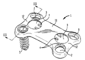
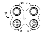
図1〜図6に関しては、第一態様によるインプラントが示されており、これは、プレート1、骨スクリュー5及び止め輪又は割リング4を含む。プレート1は、前頸部プレートのような骨プレート又は骨スクリューにより骨上に保持されるように設計された任意の他のプレートである。プレート1は、2つの骨部を結合させるか又は骨折を安定させるか又は切除された骨面、例えば脛骨プラトー(plateau)の上に位置することができる。
【0026】
有利な実施態様では、プレート1は、本体11から形成され、本体11は、その中央域の幅より僅かに大きい幅の2個の端部12で終わっている。各端部12は、プレート1の全厚みを突き抜いた開口又はオリフィス2を1対含む。4つの開口は、方形の4隅として、幾何学的に配置される。各開口2は、第一の上部円筒部23を有し、これは、球形中間部21の形に続き、第二の下部円筒部22で終わり、この22の直径は、第一円筒部23の直径より小さい。球形中間部21により、開口2に収容される骨スクリュー5の角度を選択することができる。
【0027】
プレート1は、円形開口及び凹所31を有する止まり穴3を2個含むのが有利である。この2個の止まり穴は、方形の縦中央区分で、それぞれの隅の対の近くに配置される。凹所31は、近接した1対の開口2の中に突き出し、このようにして、開放溝穴32を開口2の各対中に製造する。この溝穴32は、開口2の第一円筒部23中に位置するように形成される。
【0028】
プレート1は、その縦面に、図6に表示されるように、第一の湾曲を有する。
この湾曲13により、プレート1は、図1〜図6に記載のプレート1の施与が企画されている脊柱の部分の自然な前湾に、続くことができる。更に、プレート1は、図5に表示の横断面に第二の湾曲14を有する。この湾曲14は、プレート1を、接続すべき脊椎の本体の形状にできるだけ近く適合させる。
【0029】
各凹所31は、止め輪4を収容することができる。止め輪4は、42で割れた円形リング43の形をしている。止め輪又は割リング4は、原動手段(driving means)41を含み、この態様では、これは、リング内側に向かって突き出す取っ手である。各取っ手は、針先端ペンチ(needle nose pilers)の1対の先端を受容するように成形されていてもよい(図17参照)。
【0030】
一旦凹所31に設置されると、残りの位置、即ち開放位置で、止め輪4は、各開口2の溝穴32を抜けて、近接する一対の開口2の中に突き出す。この様にして開口2を僅かに閉鎖する。
【0031】
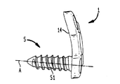
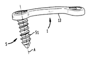
本発明に適合する脊椎本体にプレート1を接続させる態様では、骨スクリュー5は、有利な取付け部材である。好ましいスクリュー5は、骨に好適な、円筒形部又は螺子付き軸部51の上に設置されたヘッド57を有し、セルフタッピング手段(self-tapping means)55をその末端に含む。これらのタッピング手段は、駆動されると、スクリューを骨により良く突入させる。ヘッド57は、ドライブ(drive)52を含み、これは、この例では6面体ソケットにより具体化されている。更に、ヘッド57は、僅かに円錐形である部53を含み、これは、リム(rim)を形成する部56の形に続き、このリムはスクリューの外側に向けて延出し、かつスクリュー5の軸Aに垂直な面に対して、少し傾斜している。
【0032】
最後に、スクリュー5のヘッド57は、末端が球形雄部54になっており、この雄部は開口2の雌中間部21と嵌合し、この雄部下から螺子付き円筒部又は軸部51が延びている。これらの嵌合により、骨スクリュー5をプレート1に対して選択した角度で設置することができる。従って、手術の間に、外科医は、プレート1の取付けを最適にすることができる。
【0033】
好ましくは、図1〜図6に示された本発明のインプラントは、プレート1の凹所31中に2個の止め輪4を設置して、外科医に供給される。プレートが前側の頸部プレートであるならば、有利に、前側アクセスルートにより及び適合される椎骨本体を露出させて移植する。外科医は、プレート1を位置決めし、次いで取付けたい開口の各対を通る案内穴(pilot hole)を貫通させる。次いで骨スクリューを各案内穴に係合させる。ヘッド5の部54が、溝穴32を抜けて突出する止め輪4のリング44の部分に接触するまでスクリューをねじ込む。この時点で、2つの可能な選択がある:即ち
1)外科医は、ペンチを使用して、2個の取っ手41をより近接させることにより、止め輪4をぴたりととじ、次いで止め輪を閉じたままに保持しながら、2つの骨スクリュー5を、相補的球形部21と54が接触するまでねじ込み、次いで、止め輪を緩め、リム56の上の開放位置に戻す;
2)外科医は、取付け部材5を螺子締めしつづけ、坂路(ramp)効果により、球形部54がリング44を溝32の中に押し込み、このようにして通路を形成し、かつリングは、リム56が一旦通過すると、再び自動的に開き、相補的球形部21と54が接触するようにする。
【0034】
相補的球形部21と54との間の接触により、またリム56の上の止め輪4の再開放により、ロックが提供される。リム56の第二の役割は、角配向の可能性を制限することである。これは、スクリューが脊椎骨本体から出てくるのを阻止するか又は対を作っている他の開口2にフィットされた相対物と接触することを防ぐ。両方の場合に、プレートは、脊椎骨本体に不十分に取付けられるか、又は全く取付けられないことになる。従って、各スクリューを末端を介してオリフィスに導入すると、止め輪は、スクリューがオリフィスから後退するのを防止する。
【0035】
調節の場合には、外科医は、取っ手41を近づけることで止め輪4を閉じ、このようにしてオリフィス2の割れ目を露出させた後、単に骨スクリュー5を回して緩めることにより、容易にプレート1を回収することができる。
【0036】
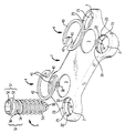
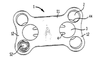
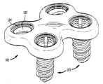
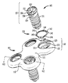
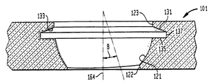
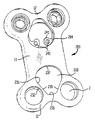
図7〜図16で示される第二の態様では、頸部プレート1は、なお、有利には、本体111から形成され、これは、本体111より僅かに広い2個の端部112で終わっている。各端部112は、更に、1対の開口102を有し、この開口は、プレート101の厚さをそっくり貫通する。各開口102は、円筒状の第一部123、次いで球形中間部121を有する。有利には、オリフィス又は開口102は、プレート101の縦方向に角をなした切欠き(cutout)の形で部122を有する。有利には、該切欠きは、スクリューが、縦方向で軸164の周りに、有利に0〜20°である角度Bで旋回することを許し、切欠き122の幅は、有利には、僅かにその長さよりも短い。円形凹所又は溝131は、各開口102の円筒状部123中に形成される。先の態様におけるように、前側の頸部プレートとして使用の場合、プレート101は、その縦面に湾曲部13を有し、かつ湾曲部14は、その横断面に有する。これらの湾曲部の役割は、先の態様のものと同じである。
【0037】
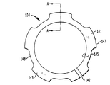
凹所131は、止め輪又は割リング104を収容することができる。前のように、止め輪104は、円形リング143の形をしており、142で割れている。この場合の好ましい止め輪又は割リング104は、リング143の全円周の周りに均一に分布するタブ(tab)141と切欠き149を有する。有利には、少なくとも3個のタブがある。止め輪は溝又は凹所131から逸れないが、他方、リング143のより薄い部分は、止め輪が変形又は拡張する際に、より柔軟なままであることを、これらのタブが確実に可能にし、このことは下記で議論されるであろう。勿論、リングを柔軟にするのに、リングを更に薄くするか又は他の手段を使用することが可能である。例えば、リング中の切欠きが必要な柔軟性を生じるのに十分な大きさであるならば、1個又は2個のタブを使用することができた。止め輪104は、リング143の内側145に位置する導入食付き部(inlet chamfer)の形で、拡張食付き部又は坂路144を含む。
【0038】
十字の形のドライブ152が、1つの態様では、スクリュー105の軸Aと共軸の止まり穴158により延伸される点で、骨スクリュー105は、先の態様のそれとは異なる。このことにより、止まり穴158を相補する小円筒状突起部により延伸された平刃又は十字形刃を備えたスクリュードライバーを使用することができる。従って、締め付け又は緩める際に、スクリュードライバーがスリップして、近くの生存組織を傷つけるか又は非可逆的に止め輪104を変形させ、これが、ロックを危険に曝すのだが、この場合は、そのような事は起こり得ない。
【0039】
有利なヘッド157は、一般に円錐形で、僅かに外向きに弧を描く部153を有し、部153は、スクリュー105の外側に向けて延伸する上向きのリム面を形成する部156に半径外方向で続き、かつ有利に、これは、スクリュー105の軸Aに垂直な面に対して僅かに傾斜する。
【0040】
最後に、開口102の中間部121と嵌合する部分的球形部154は、部154の外側エッジが螺子付き円筒部又は軸部151に合し、中間部121は、骨スクリュー螺子と共に螺子筋を付けられている。この相補性の目的は、スクリュー105の角度を、投錨を最適にするために、プレート101に対して選択することを許すことである。
【0041】
先の態様におけるように、インプラントは、プレート101の4つの凹所131に4つの割リング又は止め輪104を設置して、外科医に供給される。前記のように、アクセスルートを有する外科医は、プレート101を位置付けし、取付けたい場所の開口102の対を通して、案内穴を穿孔し、骨スクリュー105を完全にねじ込む。固定の最後に、球形部154は、止め輪104の食付き部144に接触し、次いで、圧迫作用(bearing action)により、後者を開き、オリフィス102の球形中間部121に向かう通路を形成する。止め輪104は、一旦リム156が通過すると、自動的に再び戻って閉じ、相補的球形部121と154は、接触する。
【0042】
これら2つの操作の遂行は、スクリュー105がプレート101にロックされることを確実にする。前記のように、上向きリム156の第二の役割は、角度調節の可能性を制限することである。これは、スクリューが脊椎本体から出てくるか又はその螺子付き軸部151が他の対を作るオリフィス102にフィットした相対物と接触することを防ぐ。両方の場合に、プレートは、脊椎本体に不十分に取付けられるか、又は全く取り付けられないことになる。調節の場合には、外科医は、下記に議論されるように、止め輪104を開けた後、単に骨スクリュー105を回して緩めることにより、容易にプレート101を回収することができる。
【0043】
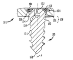
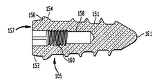
本発明の骨スクリューの有利な第二の態様は、図10に極めて詳細に示される。有利な態様では、スクリュー105の止まり穴158が、スクリュー先端161に向けて、ドライブ152下に位置する部分160で螺子筋を付けられている。螺子付き部分の機能は、下により詳細に記載するつもりである。
【0044】
有利なスクリュー105は、公称螺子直径約4mmを有し、リム156の上向き面の外側直径が約5mmであることに留意すべきである。所望の場合には、スクリュー軸部151の案内端部又は先端部161は、骨スクリューに自動ドリル及びタッピングを可能にさせるために、溝又は他の構造を含んでよい。外科医は、この状況では、案内穴をあける必要がない。
【0045】
図11には、骨プレート中に有利な開口102が示されている。ばねクリップ104を収容する凹所又は溝131は、上向き又は内向きに傾斜する面133を有し、有利な態様では、これは、溝131の底面135に対し、約20℃の角度で延伸する。有利な態様では、溝131の底面135は、開口102の軸164に垂直な面に沿って延伸する。上向きに傾斜する面133は、面137により面135から離間されており、その距離は、有利な態様では、約0.3mmである。溝131の面137に対する最大直径は、有利な態様では、約6.9mmである。スクリューヘッド157のための球形受座121は、隣接するプレートの骨接触底面から面135へと延伸する。有利な態様では、球形面は、半径2.67mmを有する。結果として、スクリューの部分球形部154は、同じ半径を有する。図11に見られるように、開口102は、プレート底面に隣接する面122の部分に沿って、角度付き切欠きを有し、このため、軸164に対し、ほぼ0°〜20°、有利には10°の角度Bで少なくとも1方向に、スクリュー軸部151を延伸させることができる。従って、底面から見ると、開口は、少なくとも1方向に長円であるように見える。もちろん、角度付き切欠きは、拡大して、複数の方向に角度をつけることができる。
【0046】
図12には、有利な割リング又は止め輪104が図示され、これは、リング143の円周に均一に分布された5個のタブ141を含む。有利な態様では、リングは、約4.5mmの内側直径145及び有利に6.2mmの最大外側直径147を有する。外側直径147と溝直径137との差は、有利に約0.7mmである。このことが、内側直径を拡張させてスクリューヘッドを収容することを可能にする。有利な切欠きは、ほぼ0.4mmの深さを有するので、各切欠きでの外側直径149は、ほぼ5.4mmである。有利な割れ目142は、割リングが、その緩んだ、即ち非拡張の状態の時、その幅は0.26mmである。上記寸法は、説明のためにのみ与えられ、より大きなスクリュー、開口及び割リングを他の適用で使用することができる。
【0047】
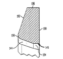
図13には、図12に示された割リングの線A−Aに沿った断面が図示される。割リングは、底面190を有し、これは、溝13の底面135に係合するように配向されている。断面は、面133に係合するために傾斜された上面192を有し、これは、割リングの中心に向けて上向きに傾斜する。有利には、その勾配は、底面190に対して、角度約20°である。内側直径145を形成する表面は、2つの区画からなっており、第一の区画は、開口102の軸164に一般に平行する面194であり、第二の区画は、面194(及び軸164)に対して有利に20°で、半径外向き方向で面192に向かう面144である。面192及び144は、有利に、鋭い角では無くむしろ丸みを持った198により接続される。有利な割リングでは、面190から丸み(radius)198のトップまでの全体の高さは、ほぼ0.52mmであり、面190と192との間の面196に沿った距離は、約0.29mmである。
【0048】
有利な断面により、ばねクリップ104がプレート製造者により溝131の中で組み立てられ、かつ予め組み立てられた状態で使用者に輸送されることが可能となる。末端使用者に輸送される前に、挿入凹所又は溝131に挿入するためには十分柔軟でなくてはならず、そのため十分多くの切欠きをクリップ104が有することは、特に重要である。リングのために相対的に柔軟な材料を使用することも必要であり、この材料は、100Gpa未満のモジュラスを有する。そのようなチタン材料は、米国特許第4857269号及び第4952236号に見られる。これらのチタン合金を、割リングに利用するならば、ジョイント部材又はプレート及び取付け部又は骨スクリューを同じ材料から製造できる利点が判明した。もっとも、そのようなことは、絶対に必要ではないのだが。更に、ポリマー材料を、割リングに使用することができる。有利な態様では、割リング104は、組立後、溝から取り外すことを可能にする手段を有さない。従って、外科医にとり、リングをプレートから取り外すことは、不可能である。
【0049】
割リングの他の利点は、溝面133と相補的に係合するトップ面192の有利な20°の傾きである。このことは好ましい。何故ならば、スクリュー105が、割リング104の底面190に逆らって後退することから生じる力が、内側直径145の拡張を抑える傾向にあるからである。更に、リング104の底面190と上向き面156との間の小さい環状の相互係合だけが、スクリュー105がプレート1の穴2から後退するのを防ぐために必要である。有利な態様では、この環状の重複は、少なくとも0.07mmであり、有利には、半径上0.07と0.11mmとの間にある。
【0050】
図17に示された第三態様では、装置201は、止まり穴203及び凹所231に収容できる止め輪204の形のみ、第一態様と異なる。穴203の形は、半円形ベース237を有し、これは、2つの直線面236に続き、これらの面は、相互に収束し、連合したオリフィス2の側の他端で、ベース237より小さい半径の半円形頂点235に接続している。この形状は、止め輪204の適合を容易にする。止め輪は、器具を駆動させる掴みあごを捕まえるための穴243を有する取っ手241を除き、第一態様のものと非常に類似する。この態様を用いての取り付けは、第一態様のものと等しい。
【0051】
この止め輪104は、一定の横断面を有する。
【0052】
骨スクリューは、単一軸であってよく、プレートに対して配向させることはできない。
【0053】
従って、図1及び図17の態様では、全く同一の止め輪が2個の取付けスクリューをロックすることをみることができる。
【0054】
これらの態様全てでは、各止め輪は、直接にスクリューと接触して、協働し、開口からこれが出てくるのを防ぎ、止め輪とスクリューとの間の中間物として作用する部を備える必要が無い。
【0055】
図18には、駆動スクリュー(driving screw)105のための好ましいスクリュードライバー300の平面図が示される。スクリュードライバー300は、ハンドル302、軸部304及びドライブヘッド306を含む。図19には、ドライブヘッド306の先端の図が示され、これは、相互に垂直な1対の刃308を有する十字形ドライブを示す。刃308は、スクリュー105のドライブ152と係合する。有利な態様では、ドライブ152を形成する十字型溝の深さは、約2mmであり、ドライブ刃308の深さは、少々浅く、かつドライブ152を形成する4つの溝の幅は、約1mmで、刃308の幅はそれより僅かに狭い。この形態は、ドライバー300上の刃とドライブ152との間の優れた係合を保証する。
【0056】
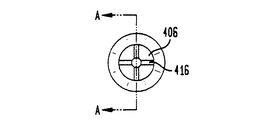
図20から図22には、スクリュー105が、骨中に完全に挿入され、割リング104により退出をブロックされた後、これを取り出すための道具が示されている。図20には、ハンドル402及びドライブ先端406を含む管状ドライブ軸404を備えた抜取り道具400が示される。ハンドル402は、ハンドル402の端部410に向けて開口する空隙408を有する管状物である。好ましい態様では、空隙408は、直径約8mmの円形である。空隙408の内部端部412は、カニューレ挿入部414に対し開き、このカニューレ挿入部は、軸404の長さに延伸し、先端406を抜ける。好ましい態様では、このカニューレ挿入部は、直径約2mmの円形である。カニューレ挿入部414の機能は、以下に記載する。
【0057】
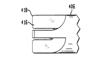
図22には、抜取り管400のドライブ先端部406の拡大図が示されており、この管は、前記のドライバーヘッド306のように、刃308と類似の十字部材416を有する十字型刃を含む。しかしながら、先端部406の外径は、スクリュー105の面156の外径に等しい。先端部406は、内側に向けて面取りされた部分418を含み、これは、先端部406を、割リングの内側直径145に係合させ、かつ十分に拡張させて、スクリューを、抜取り機400でスクリュー105を逆回しして内側直径145を通して抜き取るか引っ張り出すことを可能にする。一旦、上向き面156の最大直径が割リングを通り抜けると、リングは、スクリュー105の面154に沿って、内側にはねる。
【0058】
場合によっては、骨が悪変するので、抜取り機400でスクリュー105を逆回ししてスクリューを外す力を生じることが不可能であると判明した。この場合には、図23に、抜取り道具400の空隙408及びカニューレ挿入部414内にぴったり合うようにデザインされた抜取り道具500が示される。抜取り道具500は、上部502、軸部504、螺子付き先端部506及び拡大部分508を含む。螺子付き先端部は、スクリュー105の螺子山160に螺合する螺子すじを含む。好ましい態様では、螺子は、直径1.6mmである。従って、骨スクリュー105が抜取り機400を用いてスクリュー105を逆回しするだけでは外せない場合には、抜取り軸504をカニューレ挿入部414を通して挿入し、先端部406から出して、骨スクリュー105の螺子160に螺合させる。その時、外科医がすべき全ては、スクリュー105を骨から引き出す抜取り道具500の部分508を引き出すことである。
【図面の簡単な説明】
【図1】本発明の第一態様の斜視図である。
【図2】第一態様の分解斜視図である。
【図3】図1の第一態様のIII−III線断面図である。
【図4】第一態様の上から見た平面図である。
【図5】図4で示された第一態様の側面図である。
【図6】図4に示された第一態様の正面図である。
【図7】本発明の第二態様の斜視図である。
【図8】第二態様の分解斜視図である。
【図9】第二態様のVII−VII面での切断部分断面図である。
【図10】本発明の骨スクリュー又はアンカーの断面図である。
【図11】本発明の第二態様で使用される1個のオリフィスの、図8のVII−VII線断面図であるが、スクリュー及び割リングは含まない。
【図12】本発明の第二態様の割リングの平面図である。
【図13】図12の割リングのA−A線断面図である。
【図14】本発明の第二態様の平面図である。
【図15】図14に示された第二態様の側面図である。
【図16】図14に示された第二態様の正面図である。
【図17】本発明の第三態様の斜視図である。
【図18】図11のオリフィスから図10の骨スクリューを推進させるためのスクリュードライバーの平面図である。
【図19】図18に示されたスクリュードライバーの先端図である。
【図20】埋め込み後、アンカー又は骨スクリューをプレートから引き出すための抜取り管の平面断面図である。
【図21】図20に示された抜取り機の先端図である。
【図22】図20に示された抜取り機のドライブの拡大詳細図である。
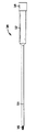
【図23】スクリューに係合し、スクリューを穴から軸方向に引き出すようにデザインされた螺子付き抜取り軸の平面図であり、螺子付き軸は捩って外せないようになっている。
【符号の説明】
1、101、201 プレート
2、102 オリフィス
3、203 止まり穴
4、104、204 割リング
5、105 骨スクリュー
13、14 湾曲
21、121 球形中間部
32 開放溝穴
51、151 軸部
52、152 ドライブ
54、154 球形雄部
56、156 リム
57、157 スクリューヘッド
122 切欠き
123 円筒状部
131 溝
133 傾斜面
135 溝底面
145 内側直径
147 外側直径
149 切欠き
158 止まり穴
164 開口の軸
190 リング底面
192 リング上面
400 抜取り機
404 ドライブ軸
406 ドライブ先端部
414 カニューレ挿入部
500 抜取り道具
504 軸部
506 螺子付き先端部
Claims (13)
- インプラントであって、
骨と接触する面と、その反対側の外側面と、前記骨接触面と前記外側面との間に延びる少なくとも1つの開口とを有するジョイント部材であって、前記開口の内側円周に溝が形成されており、この溝は、対向する2つの面を有しており、このうちの前記外側面側の面は、前記開口の中心側に向かって前記外側面側に傾斜しているジョイント部材と、
前記溝と前記骨接触面との間で、前記開口に収容可能な骨アンカーと、
前記溝内に設けられた弾力的に拡張する割リングであって、この割リングは、前記外側面側から前記開口に前記骨アンカーを挿入する際に広がり、広がっていない場合は、前記開口が有する直径より小さい内側直径を有する一方、広がる場合は、前記骨アンカーが有する最大の直径よりも大きい内側直径を有し、且つこの割リングは、前記溝が有する2つの面とそれぞれ係合する2つの面を有し、このうちの前記外側面側の面は、前記開口の中心側に向かって前記外側面側に傾斜しており、この割リングは、前記骨アンカーと直接接触して、前記開口中に挿入された骨アンカーが前記溝を超えて前記外側面の方向に後退することを妨げる、割リングと
を含むインプラント。 - 前記ジョイント部材がプレートを含む請求項1記載のインプラント。
- 前記開口が球形受座を含む請求項2記載のインプラント。
- 前記骨アンカーが、前記球形受座と接触し得る相補的球形部を含む請求項3記載のインプラント。
- 前記骨アンカーがドライブ部分を含む請求項1記載のインプラント。
- 前記割リングが、その柔軟性を最適化するために、可変性断面を有する請求項1記載のインプラント。
- 前記割リングは、各開口において特有のものである請求項1記載のインプラント。
- 前記ジョイント部材は、解剖学上の湾曲を有する請求項1記載のインプラント。
- 前記少なくとも1つの開口が、前記溝と前記骨接触面との間に位置する部分的に球形な受座部を有し、この受座部が、前記骨接触面に向かって、前記骨アンカーの軸部を受容するように開いている請求項1記載のインプラント。
- 前記骨アンカーが部分的に球形な頭部を有し、この頭部は、前記開口の前記球形受座部と係合するように前記軸部から前記外側面に向かって延びる請求項9記載のインプラント。
- 前記溝の2つの面は、前記ジョイント部材の骨接触面に最も近接する面と前記傾斜面であり、この傾斜面は前記開口の中心軸に向かって内部へと延びるとともに、前記ジョイント部材の前記外側面に向かって延びる請求項9記載のインプラント。
- 前記溝の前記骨接触面側の面は、一般にフラットであり、一般に前記開口の中心軸に対し垂直に延びる請求項11記載のインプラント。
- 前記骨アンカーの部分的に球形な頭部が前記開口の部分的球形な受座部に嵌められている場合、前記溝の骨接触面側の面は、前記骨アンカーの前記外側面側の面よりも、前記ジョイント部材の外側面により近く位置している請求項11記載のインプラント。
Applications Claiming Priority (5)
| Application Number | Priority Date | Filing Date | Title |
|---|---|---|---|
| FR0008144A FR2810532B1 (fr) | 2000-06-26 | 2000-06-26 | Implant osseux a moyens de blocage annulaires |
| FR0008144 | 2000-06-26 | ||
| US09/665530 | 2000-09-19 | ||
| US09/665,530 US6602255B1 (en) | 2000-06-26 | 2000-09-19 | Bone screw retaining system |
| US0008144 | 2000-09-19 |
Related Child Applications (2)
| Application Number | Title | Priority Date | Filing Date |
|---|---|---|---|
| JP2011130631A Division JP5645756B2 (ja) | 2000-06-26 | 2011-06-10 | 骨スクリュー保持システム |
| JP2011130632A Division JP5378455B2 (ja) | 2000-06-26 | 2011-06-10 | 骨スクリュー保持システム |
Publications (3)
| Publication Number | Publication Date |
|---|---|
| JP2002143176A JP2002143176A (ja) | 2002-05-21 |
| JP2002143176A5 JP2002143176A5 (ja) | 2008-08-14 |
| JP4792176B2 true JP4792176B2 (ja) | 2011-10-12 |
Family
ID=26212489
Family Applications (1)
| Application Number | Title | Priority Date | Filing Date |
|---|---|---|---|
| JP2001192408A Expired - Fee Related JP4792176B2 (ja) | 2000-06-26 | 2001-06-26 | 骨スクリュー保持システム |
Country Status (6)
| Country | Link |
|---|---|
| US (5) | US20030093082A1 (ja) |
| EP (1) | EP1169971B1 (ja) |
| JP (1) | JP4792176B2 (ja) |
| AU (1) | AU757023B2 (ja) |
| CA (1) | CA2351231C (ja) |
| DE (1) | DE60106525T2 (ja) |
Families Citing this family (153)
| Publication number | Priority date | Publication date | Assignee | Title |
|---|---|---|---|---|
| AU757023B2 (en) | 2000-06-26 | 2003-01-30 | Stryker European Holdings I, Llc | Bone screw retaining system |
| US20050010227A1 (en) | 2000-11-28 | 2005-01-13 | Paul Kamaljit S. | Bone support plate assembly |
| US6755833B1 (en) | 2001-12-14 | 2004-06-29 | Kamaljit S. Paul | Bone support assembly |
| US7008426B2 (en) * | 2001-12-14 | 2006-03-07 | Paul Kamaljit S | Bone treatment plate assembly |
| US7070599B2 (en) | 2002-07-24 | 2006-07-04 | Paul Kamaljit S | Bone support assembly |
| NZ533664A (en) * | 2001-12-24 | 2005-01-28 | Synthes Ag | Device for performing osteosynthesis |
| US6695846B2 (en) * | 2002-03-12 | 2004-02-24 | Spinal Innovations, Llc | Bone plate and screw retaining mechanism |
| US8105366B2 (en) | 2002-05-30 | 2012-01-31 | Warsaw Orthopedic, Inc. | Laminoplasty plate with flanges |
| CN100496425C (zh) * | 2002-07-16 | 2009-06-10 | 华沙整形外科股份有限公司 | 固定骨节段的板系统 |
| US7004944B2 (en) | 2002-07-16 | 2006-02-28 | Sdgi Holdings, Inc. | Bone plate fastener retaining mechanisms and methods |
| US6989012B2 (en) | 2002-07-16 | 2006-01-24 | Sdgi Holdings, Inc. | Plating system for stabilizing a bony segment |
| US7060067B2 (en) | 2002-08-16 | 2006-06-13 | Sdgi Holdings, Inc. | Systems, instrumentation and techniques for retaining fasteners relative to a bone plate |
| US7179260B2 (en) | 2003-09-29 | 2007-02-20 | Smith & Nephew, Inc. | Bone plates and bone plate assemblies |
| US7250054B2 (en) | 2002-08-28 | 2007-07-31 | Smith & Nephew, Inc. | Systems, methods, and apparatuses for clamping and reclamping an orthopedic surgical cable |
| CN101056591A (zh) | 2002-10-28 | 2007-10-17 | 黑石医药股份有限公司 | 设置有螺钉锁定结构的骨板组件 |
| WO2004071276A2 (en) | 2003-02-05 | 2004-08-26 | Pioneer Laboratories, Inc. | Bone plate system |
| US7309340B2 (en) | 2003-06-20 | 2007-12-18 | Medicinelodge, Inc. | Method and apparatus for bone plating |
| US7087057B2 (en) | 2003-06-27 | 2006-08-08 | Depuy Acromed, Inc. | Polyaxial bone screw |
| KR100552117B1 (ko) * | 2003-07-22 | 2006-02-13 | 유앤아이 주식회사 | 경추고정장치 및 이에 사용되는 드라이버 |
| US7909860B2 (en) | 2003-09-03 | 2011-03-22 | Synthes Usa, Llc | Bone plate with captive clips |
| US20050049595A1 (en) | 2003-09-03 | 2005-03-03 | Suh Sean S. | Track-plate carriage system |
| US7857839B2 (en) | 2003-09-03 | 2010-12-28 | Synthes Usa, Llc | Bone plate with captive clips |
| US8105367B2 (en) | 2003-09-29 | 2012-01-31 | Smith & Nephew, Inc. | Bone plate and bone plate assemblies including polyaxial fasteners |
| US8062367B2 (en) | 2003-09-30 | 2011-11-22 | X-Spine Systems, Inc. | Screw locking mechanism and method |
| US7182782B2 (en) * | 2003-09-30 | 2007-02-27 | X-Spine Systems, Inc. | Spinal fusion system and method for fusing spinal bones |
| US8372152B2 (en) | 2003-09-30 | 2013-02-12 | X-Spine Systems, Inc. | Spinal fusion system utilizing an implant plate having at least one integral lock and ratchet lock |
| US8821553B2 (en) | 2003-09-30 | 2014-09-02 | X-Spine Systems, Inc. | Spinal fusion system utilizing an implant plate having at least one integral lock |
| US9078706B2 (en) | 2003-09-30 | 2015-07-14 | X-Spine Systems, Inc. | Intervertebral fusion device utilizing multiple mobile uniaxial and bidirectional screw interface plates |
| US7641701B2 (en) | 2003-09-30 | 2010-01-05 | X-Spine Systems, Inc. | Spinal fusion system and method for fusing spinal bones |
| US7306605B2 (en) | 2003-10-02 | 2007-12-11 | Zimmer Spine, Inc. | Anterior cervical plate |
| US7655009B2 (en) | 2003-12-01 | 2010-02-02 | Smith & Nephew, Inc. | Humeral nail |
| US8900277B2 (en) | 2004-02-26 | 2014-12-02 | Pioneer Surgical Technology, Inc. | Bone plate system |
| US7740649B2 (en) | 2004-02-26 | 2010-06-22 | Pioneer Surgical Technology, Inc. | Bone plate system and methods |
| US20050216027A1 (en) * | 2004-03-24 | 2005-09-29 | Suh Sean S | Extraction screwdriver |
| USD536453S1 (en) * | 2004-03-25 | 2007-02-06 | Precimed S.A. | Bone plate |
| US10478179B2 (en) * | 2004-04-27 | 2019-11-19 | Covidien Lp | Absorbable fastener for hernia mesh fixation |
| US7727266B2 (en) | 2004-06-17 | 2010-06-01 | Warsaw Orthopedic, Inc. | Method and apparatus for retaining screws in a plate |
| US8469966B2 (en) | 2004-09-23 | 2013-06-25 | Smith & Nephew, Inc. | Systems, methods, and apparatuses for tensioning an orthopedic surgical cable |
| US9615866B1 (en) | 2004-10-18 | 2017-04-11 | Nuvasive, Inc. | Surgical fixation system and related methods |
| US7931678B2 (en) | 2004-12-08 | 2011-04-26 | Depuy Spine, Inc. | Hybrid spinal plates |
| US7935137B2 (en) | 2004-12-08 | 2011-05-03 | Depuy Spine, Inc. | Locking bone screw and spinal plate system |
| US8152838B2 (en) * | 2005-02-18 | 2012-04-10 | Alphatec Spine, Inc. | Orthopedic plate system and method for using the same |
| US8052729B2 (en) * | 2005-03-16 | 2011-11-08 | Stryker Spine | Anterior lumbar lag plate |
| AU2012211502B2 (en) * | 2005-03-17 | 2014-09-18 | Spinal Elements, Inc. | Implant and method for treating a spine |
| US8496708B2 (en) | 2005-03-17 | 2013-07-30 | Spinal Elements, Inc. | Flanged interbody fusion device with hinge |
| US7452370B2 (en) | 2005-04-29 | 2008-11-18 | Warsaw Orthopedic, Inc | Apparatus for retaining a bone anchor in a bone plate and method for use thereof |
| US7288094B2 (en) * | 2005-06-10 | 2007-10-30 | Sdgi Holdings, Inc. | System and method for retaining screws relative to a vertebral plate |
| US8382807B2 (en) | 2005-07-25 | 2013-02-26 | Smith & Nephew, Inc. | Systems and methods for using polyaxial plates |
| EP1919385B1 (en) | 2005-07-25 | 2014-08-20 | Smith & Nephew, Inc. | Polyaxial plates |
| KR100656186B1 (ko) | 2005-08-31 | 2006-12-13 | 주식회사 솔고 바이오메디칼 | 다중축 압박 고정장치 |
| CN101296663B (zh) * | 2005-10-25 | 2011-05-25 | 圣歌整形外科有限责任公司 | 骨固定组件及与其一起使用的套管和螺钉 |
| WO2007076050A1 (en) * | 2005-12-21 | 2007-07-05 | Synthes (U.S.A.) | Resorbable anterior cervical plating system with screw retention mechanism |
| US8100952B2 (en) * | 2005-12-22 | 2012-01-24 | Anthem Orthopaedics Llc | Drug delivering bone plate and method and targeting device for use therewith |
| US7771484B2 (en) * | 2006-02-28 | 2010-08-10 | Howmedica Osteonics Corp. | Modular tibial implant |
| US8728128B2 (en) * | 2006-03-21 | 2014-05-20 | Nexus Spine, L.L.C. | Cervical pop rivet locking mechanism |
| US8303601B2 (en) * | 2006-06-07 | 2012-11-06 | Stryker Spine | Collet-activated distraction wedge inserter |
| US20120232595A1 (en) | 2011-03-07 | 2012-09-13 | Tyler HOLSCHLAG | Fastener retention system for spinal plates |
| ES2611609T3 (es) * | 2006-06-30 | 2017-05-09 | Alphatec Spine, Inc. | Sistemas de placa para fijación ósea |
| US8361130B2 (en) | 2006-10-06 | 2013-01-29 | Depuy Spine, Inc. | Bone screw fixation |
| US8142432B2 (en) * | 2007-02-05 | 2012-03-27 | Synthes Usa, Llc | Apparatus for repositioning portions of fractured bone and method of using same |
| US9545275B2 (en) | 2007-05-18 | 2017-01-17 | Us Spine, Inc. | Medical device locking mechanisms and related methods and systems |
| US8721693B2 (en) * | 2007-05-18 | 2014-05-13 | Us Spine, Inc. | Cervical plate locking mechanism and associated surgical method |
| US8840650B2 (en) * | 2007-05-18 | 2014-09-23 | Us Spine, Inc. | Cervical plate locking mechanism and associated surgical method |
| US9072548B2 (en) * | 2007-06-07 | 2015-07-07 | Anthem Orthopaedics Llc | Spine repair assembly |
| US8623019B2 (en) | 2007-07-03 | 2014-01-07 | Pioneer Surgical Technology, Inc. | Bone plate system |
| US8361126B2 (en) | 2007-07-03 | 2013-01-29 | Pioneer Surgical Technology, Inc. | Bone plate system |
| US20090177239A1 (en) * | 2007-08-06 | 2009-07-09 | Michael Castro | Cervical plate instrument kit |
| US20110319943A1 (en) | 2007-08-20 | 2011-12-29 | Ryan Donahoe | Surgical Fixation System and Related Methods |
| US8343194B2 (en) * | 2007-08-20 | 2013-01-01 | Kamran Aflatoon | Anterior cervical staple |
| US8496693B2 (en) | 2007-10-16 | 2013-07-30 | Amendia Inc. | Bone screw retaining and removal system |
| US8998964B2 (en) | 2007-10-16 | 2015-04-07 | Spectrum Spine, LLC | Bone screw retaining and removal system |
| US20090149862A1 (en) * | 2007-12-10 | 2009-06-11 | Sym Partners, Llc | Guide pin for pedicle screw placement and method for use of such guide pin in spinal fusion surgeries |
| US8282675B2 (en) * | 2008-01-25 | 2012-10-09 | Depuy Spine, Inc. | Anti-backout mechanism |
| US20110106159A1 (en) * | 2008-06-05 | 2011-05-05 | Seaspine, Inc. | Spinal fixation plate assembly |
| US20090326545A1 (en) * | 2008-06-26 | 2009-12-31 | Amedica Corporation | Systems and methods for inserting a bone anchor without a pilot hole |
| US8273111B2 (en) * | 2008-07-02 | 2012-09-25 | Ebi, Llc | Growth control device |
| US8795340B2 (en) | 2008-11-07 | 2014-08-05 | Globus Medical, Inc. | Vertical inline plate |
| US20100121383A1 (en) * | 2008-11-10 | 2010-05-13 | Todd Stanaford | Method, system, and apparatus for mammalian bony segment stabilization |
| US8821554B2 (en) | 2008-11-10 | 2014-09-02 | Amendia, Inc. | Method, system, and apparatus for mammalian bony segment stabilization |
| US20100217399A1 (en) * | 2009-02-22 | 2010-08-26 | Groh Gordon I | Base plate system for shoulder arthroplasty and method of using the same |
| US8574270B2 (en) | 2009-03-13 | 2013-11-05 | Spinal Simplicity Llc | Bone plate assembly with bone screw retention features |
| WO2010105279A1 (en) | 2009-03-13 | 2010-09-16 | Harold Hess | Dynamic vertebral column plate system |
| US9220547B2 (en) | 2009-03-27 | 2015-12-29 | Spinal Elements, Inc. | Flanged interbody fusion device |
| CH700839A2 (de) | 2009-04-20 | 2010-10-29 | Creaholic Sa | Befestigungsvorrichtung für chirurgische haltesysteme. |
| US9095444B2 (en) | 2009-07-24 | 2015-08-04 | Warsaw Orthopedic, Inc. | Implant with an interference fit fastener |
| FR2948553B1 (fr) * | 2009-07-30 | 2012-06-08 | Clariance | Dispositif anti recul a tiroirs pour prothese |
| USD734853S1 (en) | 2009-10-14 | 2015-07-21 | Nuvasive, Inc. | Bone plate |
| US8747443B2 (en) * | 2009-10-21 | 2014-06-10 | International Spinal Innovations, Llc | Spinal plate with compression locking |
| US20110106157A1 (en) * | 2009-10-30 | 2011-05-05 | Warsaw Orthropedic, Inc. | Self-Locking Interference Bone Screw for use with Spinal Implant |
| US8756819B2 (en) * | 2010-04-12 | 2014-06-24 | Bettcher Industries, Inc. | Power operated rotary knife with disposable blade support assembly |
| US8858603B1 (en) | 2010-06-09 | 2014-10-14 | Choice Spine, L.P. | Cervical plate with screw retention clip |
| JP5833654B2 (ja) * | 2010-08-17 | 2015-12-16 | リダインズ メディカル エルエルシー | 軟組織を骨に取り付けるための方法及び装置 |
| US8784027B2 (en) | 2010-09-14 | 2014-07-22 | Enduralock, Llc | Ratchet locking mechanism for threaded fastener |
| US9657766B2 (en) | 2010-09-14 | 2017-05-23 | Enduralock, Llc | Tools and ratchet locking mechanisms for threaded fasteners |
| US8562656B2 (en) | 2010-10-15 | 2013-10-22 | Warsaw Orrthopedic, Inc. | Retaining mechanism |
| US8940030B1 (en) | 2011-01-28 | 2015-01-27 | Nuvasive, Inc. | Spinal fixation system and related methods |
| US8668723B2 (en) | 2011-07-19 | 2014-03-11 | Neurostructures, Inc. | Anterior cervical plate |
| US10149707B2 (en) * | 2011-08-17 | 2018-12-11 | Globus Medical, Inc. | Bone fixation plate system and method |
| US9351768B2 (en) * | 2011-08-26 | 2016-05-31 | Life Spine, Inc. | Bone screw retention in a spinal implant |
| US11123117B1 (en) | 2011-11-01 | 2021-09-21 | Nuvasive, Inc. | Surgical fixation system and related methods |
| US8784459B2 (en) * | 2012-01-17 | 2014-07-22 | Genesys Spine | Spinal plate and locking screw devices, methods, and systems |
| US8734495B2 (en) | 2012-01-18 | 2014-05-27 | Globus Medical, Inc. | Securing fasteners |
| US8974504B2 (en) | 2012-05-10 | 2015-03-10 | Spinal Simplicity Llc | Dynamic bone fracture plates |
| KR101331429B1 (ko) * | 2012-08-03 | 2013-11-21 | 주식회사 솔고 바이오메디칼 | 걸쇠식 경추고정장치 |
| US20140039554A1 (en) * | 2012-08-03 | 2014-02-06 | Seo-Kon Kim | Apparatus for fixing a cervical spine having self tension part |
| US9480475B2 (en) | 2012-08-15 | 2016-11-01 | DePuy Synthes Products, Inc. | Bone plate suture anchor |
| WO2014062690A1 (en) * | 2012-10-19 | 2014-04-24 | Deroyal Industries, Inc. | Cervical plate with retaining clip |
| US9642652B2 (en) * | 2013-02-13 | 2017-05-09 | Choice Spine, Lp | Variable angle bone plate with semi-constrained articulating screw |
| JP5510874B1 (ja) * | 2013-03-11 | 2014-06-04 | 多摩メディカル有限会社 | 医療用スクリュー及び該医療用スクリューの抜去操作治具 |
| US9943341B2 (en) | 2013-07-16 | 2018-04-17 | K2M, Llc | Retention plate member for a spinal plate system |
| US9510880B2 (en) | 2013-08-13 | 2016-12-06 | Zimmer, Inc. | Polyaxial locking mechanism |
| US9468479B2 (en) | 2013-09-06 | 2016-10-18 | Cardinal Health 247, Inc. | Bone plate |
| US9629664B2 (en) | 2014-01-20 | 2017-04-25 | Neurostructures, Inc. | Anterior cervical plate |
| US9486250B2 (en) | 2014-02-20 | 2016-11-08 | Mastros Innovations, LLC. | Lateral plate |
| US9421053B2 (en) | 2014-05-08 | 2016-08-23 | Titan Spine, Llc | Implant fixation assemblies having a screw and C-shaped fixation collar |
| US9913672B2 (en) | 2014-05-28 | 2018-03-13 | Genesys Spine | Resiliant spinal plate system |
| WO2016122868A1 (en) | 2015-01-27 | 2016-08-04 | Spinal Elements, Inc. | Facet joint implant |
| US9987052B2 (en) | 2015-02-24 | 2018-06-05 | X-Spine Systems, Inc. | Modular interspinous fixation system with threaded component |
| US10215217B2 (en) | 2015-04-17 | 2019-02-26 | Enduralock, Llc | Locking fastener with deflectable lock |
| US10125807B2 (en) | 2015-09-08 | 2018-11-13 | Enduralock, Llc | Locking mechanisms with deflectable washer members |
| US10801540B2 (en) | 2015-04-17 | 2020-10-13 | Enduralock, Llc | Locking mechanisms with deflectable lock member |
| US9841046B2 (en) | 2015-04-17 | 2017-12-12 | Enduralock, Llc | Locking fastener with deflectable lock |
| KR101720142B1 (ko) * | 2016-01-18 | 2017-03-27 | 주식회사 메타바이오메드 | 경추 고정 장치 |
| US10426535B2 (en) | 2017-01-05 | 2019-10-01 | Stryker European Holdings I, Llc | Self-holding screw head |
| US10980641B2 (en) | 2017-05-04 | 2021-04-20 | Neurostructures, Inc. | Interbody spacer |
| US10512547B2 (en) | 2017-05-04 | 2019-12-24 | Neurostructures, Inc. | Interbody spacer |
| US11304734B2 (en) | 2017-11-16 | 2022-04-19 | Globus Medical Inc. | Anterior cervical plate assembly |
| US11272963B2 (en) | 2017-11-16 | 2022-03-15 | Globus Medical, Inc. | Anterior cervical plate assembly |
| US11234742B2 (en) | 2017-11-16 | 2022-02-01 | Globus Medical, Inc. | Anterior cervical plate assembly |
| US11229460B2 (en) | 2017-11-16 | 2022-01-25 | Globus Medical, Inc. | Anterior cervical plate assembly |
| US20210000509A1 (en) * | 2018-03-02 | 2021-01-07 | Scot Hodkiewicz | Pin fastener with removeable drill bit for bone fixator |
| EP4108194B1 (en) | 2018-03-02 | 2025-10-29 | Stryker European Operations Limited | Bone plates and associated screws |
| US11076892B2 (en) * | 2018-08-03 | 2021-08-03 | Neurostructures, Inc. | Anterior cervical plate |
| US11382769B2 (en) | 2018-09-20 | 2022-07-12 | Spinal Elements, Inc. | Spinal implant device |
| EP3856042B1 (en) * | 2018-09-27 | 2025-07-02 | Triqueue Holdings, Llc | Implant systems, plates, bone fusion systems |
| US11071629B2 (en) | 2018-10-13 | 2021-07-27 | Neurostructures Inc. | Interbody spacer |
| JP7281160B2 (ja) * | 2018-10-30 | 2023-05-25 | 株式会社ホムズ技研 | 骨固定システム |
| US11111950B2 (en) | 2019-04-01 | 2021-09-07 | Enduralock, Llc | Locking mechanisms with deflectable lock member |
| US11857224B2 (en) * | 2019-06-30 | 2024-01-02 | Innovasis, Inc. | Bone plate |
| KR102231234B1 (ko) * | 2019-07-09 | 2021-03-24 | 충남대학교산학협력단 | 외과용 다각 잠김 나사 제거 장치 |
| US10743922B1 (en) | 2019-09-27 | 2020-08-18 | Trilliant Surgical Llc | Variable angle locking construct for orthopedic applications |
| US11173042B2 (en) | 2019-11-26 | 2021-11-16 | GetSet Surgical SA | Spinal surgery devices, systems, and methods |
| USD925740S1 (en) | 2019-11-26 | 2021-07-20 | GetSet Surgical SA | Spinal fusion cage |
| US11278426B2 (en) | 2019-11-26 | 2022-03-22 | GetSet Surgical SA | Spinal surgery assemblies, systems, and methods |
| US11273057B2 (en) | 2019-11-26 | 2022-03-15 | GetSet Surgical SA | Spinal surgery instruments, systems, and methods |
| US11877779B2 (en) | 2020-03-26 | 2024-01-23 | Xtant Medical Holdings, Inc. | Bone plate system |
| US11382761B2 (en) | 2020-04-11 | 2022-07-12 | Neurostructures, Inc. | Expandable interbody spacer |
| US11304817B2 (en) | 2020-06-05 | 2022-04-19 | Neurostructures, Inc. | Expandable interbody spacer |
| USD949341S1 (en) | 2020-09-29 | 2022-04-19 | Trilliant Surgical Llc | Bone fixation plate |
| WO2022109524A1 (en) | 2020-11-19 | 2022-05-27 | Spinal Elements, Inc. | Curved expandable interbody devices and deployment tools |
| US11717419B2 (en) | 2020-12-10 | 2023-08-08 | Neurostructures, Inc. | Expandable interbody spacer |
| WO2022133456A1 (en) | 2020-12-17 | 2022-06-23 | Spinal Elements, Inc. | Spinal implant device |
| WO2025023347A1 (ko) * | 2023-07-26 | 2025-01-30 | 주식회사 에이스메디코프 | 3d 프린팅 기술을 이용한 환자 골 맞춤형 경추 고정판 |
Family Cites Families (68)
| Publication number | Priority date | Publication date | Assignee | Title |
|---|---|---|---|---|
| US872897A (en) | 1907-08-31 | 1907-12-03 | John W Chapman | Nut-lock. |
| US2248054A (en) * | 1939-06-07 | 1941-07-08 | Becker Joseph | Screw driver |
| US2620000A (en) * | 1950-10-14 | 1952-12-02 | Harold E Noffsinger | Screw holding attachment for screw drivers |
| US3741205A (en) | 1971-06-14 | 1973-06-26 | K Markolf | Bone fixation plate |
| DE2554555C2 (de) * | 1973-05-31 | 1984-06-14 | Waldes Kohinoor Inc., Long Island, N.Y. | Sicherungsring |
| JPS5632650Y2 (ja) * | 1975-03-25 | 1981-08-03 | ||
| JPS51119455A (en) | 1975-04-12 | 1976-10-20 | Katsuyuki Totsu | Improved screw |
| US4877020A (en) * | 1984-11-30 | 1989-10-31 | Vich Jose M O | Apparatus for bone graft |
| DE8513288U1 (de) | 1985-05-06 | 1986-09-04 | Wolter, Dietmar, Prof. Dr., 2000 Hamburg | Osteosyntheseplatte |
| JPS63157458A (ja) | 1986-12-22 | 1988-06-30 | Tokuriki Honten Co Ltd | リ−ドピン |
| CA1333209C (en) | 1988-06-28 | 1994-11-29 | Gary Karlin Michelson | Artificial spinal fusion implants |
| US4857269A (en) * | 1988-09-09 | 1989-08-15 | Pfizer Hospital Products Group Inc. | High strength, low modulus, ductile, biopcompatible titanium alloy |
| US4952236A (en) * | 1988-09-09 | 1990-08-28 | Pfizer Hospital Products Group, Inc. | Method of making high strength, low modulus, ductile, biocompatible titanium alloy |
| JPH0631215Y2 (ja) * | 1988-11-30 | 1994-08-22 | 京セラ株式会社 | ネジの抜け防止機構 |
| IT1232572B (it) | 1989-02-10 | 1992-02-26 | Calderale Pasquale Mario | Mezzi di osteosintesi per il collegamento di segmenti di fratture ossee |
| US5041116A (en) | 1990-05-21 | 1991-08-20 | Wilson James T | Compression hip screw system |
| US5797918A (en) * | 1991-12-13 | 1998-08-25 | David A. McGuire | Flexible surgical screwdriver and methods of arthroscopic ligament reconstruction |
| DE69320593T2 (de) | 1992-11-25 | 1999-03-04 | Codman & Shurtleff, Inc., Randolph, Mass. | Knochenplattensystem |
| US5364399A (en) * | 1993-02-05 | 1994-11-15 | Danek Medical, Inc. | Anterior cervical plating system |
| US5423826A (en) | 1993-02-05 | 1995-06-13 | Danek Medical, Inc. | Anterior cervical plate holder/drill guide and method of use |
| US5431660A (en) * | 1993-11-30 | 1995-07-11 | Burke; Dennis W. | Spring loaded screw and driver/extractor therefor |
| US5885299A (en) * | 1994-09-15 | 1999-03-23 | Surgical Dynamics, Inc. | Apparatus and method for implant insertion |
| JP3501542B2 (ja) * | 1995-04-07 | 2004-03-02 | 富久 腰野 | 医用硬組織代替部材および人工関節 |
| US5520690A (en) | 1995-04-13 | 1996-05-28 | Errico; Joseph P. | Anterior spinal polyaxial locking screw plate assembly |
| US5578034A (en) * | 1995-06-07 | 1996-11-26 | Danek Medical, Inc. | Apparatus for preventing screw backout in a bone plate fixation system |
| DE29521456U1 (de) | 1995-12-07 | 1997-05-07 | Aesculap Ag, 78532 Tuttlingen | Orthopädisches Haltesystem |
| GB9613916D0 (en) * | 1996-07-03 | 1996-09-04 | Dall Vagn E | Cortical bone screw |
| AU6268798A (en) | 1997-02-11 | 1998-08-26 | Gary Karlin Michelson | Anterior cervical plating system, instrumentation, and method of installation |
| CA2523814C (en) | 1997-02-11 | 2007-02-06 | Gary Karlin Michelson | Segmentable skeletal plating system |
| ZA983955B (en) * | 1997-05-15 | 2001-08-13 | Sdgi Holdings Inc | Anterior cervical plating system. |
| US6454769B2 (en) * | 1997-08-04 | 2002-09-24 | Spinal Concepts, Inc. | System and method for stabilizing the human spine with a bone plate |
| CA2311803A1 (en) | 1997-10-24 | 1999-05-06 | Robert S. Bray, Jr. | Bone plate and bone screw guide mechanism |
| US5951558A (en) | 1998-04-22 | 1999-09-14 | Fiz; Daniel | Bone fixation device |
| FR2778088B1 (fr) | 1998-04-30 | 2000-09-08 | Materiel Orthopedique En Abreg | Implant anterieur notamment pour le rachis cervical |
| US20040220571A1 (en) | 1998-04-30 | 2004-11-04 | Richard Assaker | Bone plate assembly |
| US6533786B1 (en) | 1999-10-13 | 2003-03-18 | Sdgi Holdings, Inc. | Anterior cervical plating system |
| US6258089B1 (en) * | 1998-05-19 | 2001-07-10 | Alphatec Manufacturing, Inc. | Anterior cervical plate and fixation system |
| US6090111A (en) * | 1998-06-17 | 2000-07-18 | Surgical Dynamics, Inc. | Device for securing spinal rods |
| US6436100B1 (en) * | 1998-08-07 | 2002-08-20 | J. Lee Berger | Cannulated internally threaded bone screw and reduction driver device |
| FR2784570B1 (fr) | 1998-10-19 | 2001-02-16 | Scient X | Dispositif de liaison intervertebrale equipe de moyens d'anti-extraction pour les vis d'ancrage |
| US7094239B1 (en) | 1999-05-05 | 2006-08-22 | Sdgi Holdings, Inc. | Screws of cortical bone and method of manufacture thereof |
| FR2794963B1 (fr) * | 1999-06-17 | 2001-09-07 | Eurosurgical | Dispositif anti-recul pour implant orthopedique |
| US6261291B1 (en) | 1999-07-08 | 2001-07-17 | David J. Talaber | Orthopedic implant assembly |
| US6602256B1 (en) | 1999-10-11 | 2003-08-05 | Cross Medical Products, Inc. | Bone stabilization plate with a secured-locking mechanism for cervical fixation |
| US6224602B1 (en) | 1999-10-11 | 2001-05-01 | Interpore Cross International | Bone stabilization plate with a secured-locking mechanism for cervical fixation |
| US6692503B2 (en) | 1999-10-13 | 2004-02-17 | Sdgi Holdings, Inc | System and method for securing a plate to the spinal column |
| US6331179B1 (en) * | 2000-01-06 | 2001-12-18 | Spinal Concepts, Inc. | System and method for stabilizing the human spine with a bone plate |
| US6440136B1 (en) * | 2000-05-24 | 2002-08-27 | Medtronic Ps Medical, Inc. | Apparatus for attaching to bone |
| AU757023B2 (en) | 2000-06-26 | 2003-01-30 | Stryker European Holdings I, Llc | Bone screw retaining system |
| FR2810532B1 (fr) * | 2000-06-26 | 2003-05-30 | Stryker Spine Sa | Implant osseux a moyens de blocage annulaires |
| WO2002003885A2 (en) | 2000-07-10 | 2002-01-17 | Michelson Gary K | Flanged interbody spinal fusion implants |
| US6605090B1 (en) | 2000-10-25 | 2003-08-12 | Sdgi Holdings, Inc. | Non-metallic implant devices and intra-operative methods for assembly and fixation |
| US20050010227A1 (en) | 2000-11-28 | 2005-01-13 | Paul Kamaljit S. | Bone support plate assembly |
| US6503250B2 (en) | 2000-11-28 | 2003-01-07 | Kamaljit S. Paul | Bone support assembly |
| US6413259B1 (en) | 2000-12-14 | 2002-07-02 | Blackstone Medical, Inc | Bone plate assembly including a screw retaining member |
| TW499953U (en) * | 2000-12-19 | 2002-08-21 | Jr-Yi Lin | Spine fastening reposition device |
| FR2823096B1 (fr) | 2001-04-06 | 2004-03-19 | Materiel Orthopedique En Abreg | Plaque pour dispositif d'osteosynthese des vertebres l5 et s1, dispositif d'osteosynthese incluant une telle plaque, et instrument pour la pose d'une telle plaque |
| US6599290B2 (en) * | 2001-04-17 | 2003-07-29 | Ebi, L.P. | Anterior cervical plating system and associated method |
| JP4283665B2 (ja) | 2001-06-04 | 2009-06-24 | ウォーソー・オーソペディック・インコーポレーテッド | 可動セグメントを有する前方頸椎用動的平板 |
| US7186256B2 (en) | 2001-06-04 | 2007-03-06 | Warsaw Orthopedic, Inc. | Dynamic, modular, single-lock anterior cervical plate system having assembleable and movable segments |
| US7097645B2 (en) | 2001-06-04 | 2006-08-29 | Sdgi Holdings, Inc. | Dynamic single-lock anterior cervical plate system having non-detachably fastened and moveable segments |
| US7041105B2 (en) | 2001-06-06 | 2006-05-09 | Sdgi Holdings, Inc. | Dynamic, modular, multilock anterior cervical plate system having detachably fastened assembleable and moveable segments |
| US7044952B2 (en) | 2001-06-06 | 2006-05-16 | Sdgi Holdings, Inc. | Dynamic multilock anterior cervical plate system having non-detachably fastened and moveable segments |
| US6890335B2 (en) | 2001-08-24 | 2005-05-10 | Zimmer Spine, Inc. | Bone fixation device |
| US7008426B2 (en) | 2001-12-14 | 2006-03-07 | Paul Kamaljit S | Bone treatment plate assembly |
| US6755833B1 (en) | 2001-12-14 | 2004-06-29 | Kamaljit S. Paul | Bone support assembly |
| US7070599B2 (en) | 2002-07-24 | 2006-07-04 | Paul Kamaljit S | Bone support assembly |
| US7524325B2 (en) * | 2002-11-04 | 2009-04-28 | Farid Bruce Khalili | Fastener retention system |
-
2001
- 2001-06-25 AU AU54037/01A patent/AU757023B2/en not_active Ceased
- 2001-06-26 JP JP2001192408A patent/JP4792176B2/ja not_active Expired - Fee Related
- 2001-06-26 CA CA002351231A patent/CA2351231C/en not_active Expired - Fee Related
- 2001-06-26 DE DE60106525T patent/DE60106525T2/de not_active Expired - Lifetime
- 2001-06-26 EP EP01401688A patent/EP1169971B1/en not_active Expired - Lifetime
-
2002
- 2002-12-30 US US10/331,212 patent/US20030093082A1/en not_active Abandoned
-
2005
- 2005-02-17 US US11/060,171 patent/US7887547B2/en not_active Expired - Fee Related
-
2011
- 2011-01-06 US US12/985,733 patent/US8287550B2/en not_active Expired - Fee Related
-
2012
- 2012-09-20 US US13/623,269 patent/US8734496B2/en not_active Expired - Fee Related
-
2014
- 2014-05-08 US US14/272,922 patent/US9186189B2/en not_active Expired - Fee Related
Also Published As
| Publication number | Publication date |
|---|---|
| US8287550B2 (en) | 2012-10-16 |
| US20130066379A1 (en) | 2013-03-14 |
| US20050149027A1 (en) | 2005-07-07 |
| EP1169971A3 (en) | 2002-07-17 |
| US8734496B2 (en) | 2014-05-27 |
| DE60106525T2 (de) | 2005-10-13 |
| US20140243909A1 (en) | 2014-08-28 |
| CA2351231A1 (en) | 2001-12-26 |
| AU5403701A (en) | 2002-01-03 |
| JP2002143176A (ja) | 2002-05-21 |
| EP1169971A2 (en) | 2002-01-09 |
| US20110152944A1 (en) | 2011-06-23 |
| EP1169971B1 (en) | 2004-10-20 |
| DE60106525D1 (de) | 2004-11-25 |
| CA2351231C (en) | 2006-04-04 |
| US20030093082A1 (en) | 2003-05-15 |
| US7887547B2 (en) | 2011-02-15 |
| US9186189B2 (en) | 2015-11-17 |
| AU757023B2 (en) | 2003-01-30 |
Similar Documents
| Publication | Publication Date | Title |
|---|---|---|
| JP4792176B2 (ja) | 骨スクリュー保持システム | |
| JP5378455B2 (ja) | 骨スクリュー保持システム | |
| US8672985B2 (en) | Bone fasteners and method for stabilizing vertebral bone facets using the bone fasteners | |
| US9730804B2 (en) | Locking spinal fusion device | |
| US6402756B1 (en) | Longitudinal plate assembly having an adjustable length | |
| US6331179B1 (en) | System and method for stabilizing the human spine with a bone plate | |
| US6689134B2 (en) | Longitudinal plate assembly having an adjustable length | |
| US7625375B2 (en) | Systems and techniques for stabilizing the spine and placing stabilization systems | |
| US20220071665A1 (en) | Modular tulip assembly | |
| US20060293748A1 (en) | Prosthetic implant, and a method and tool for the insertion of same | |
| CN101098661A (zh) | 侧加载椎骨锚件 | |
| JP2007505685A (ja) | 骨固定システム | |
| US20230397940A1 (en) | Bone screw with cutting tip | |
| US12336743B2 (en) | Polyaxial surgical screw and device for implanting said surgical screw |
Legal Events
| Date | Code | Title | Description |
|---|---|---|---|
| A521 | Request for written amendment filed |
Free format text: JAPANESE INTERMEDIATE CODE: A523 Effective date: 20080605 |
|
| A621 | Written request for application examination |
Free format text: JAPANESE INTERMEDIATE CODE: A621 Effective date: 20080605 |
|
| A521 | Request for written amendment filed |
Free format text: JAPANESE INTERMEDIATE CODE: A523 Effective date: 20080627 |
|
| A131 | Notification of reasons for refusal |
Free format text: JAPANESE INTERMEDIATE CODE: A131 Effective date: 20101210 |
|
| A601 | Written request for extension of time |
Free format text: JAPANESE INTERMEDIATE CODE: A601 Effective date: 20110310 |
|
| A602 | Written permission of extension of time |
Free format text: JAPANESE INTERMEDIATE CODE: A602 Effective date: 20110315 |
|
| A521 | Request for written amendment filed |
Free format text: JAPANESE INTERMEDIATE CODE: A523 Effective date: 20110610 |
|
| TRDD | Decision of grant or rejection written | ||
| A01 | Written decision to grant a patent or to grant a registration (utility model) |
Free format text: JAPANESE INTERMEDIATE CODE: A01 Effective date: 20110701 |
|
| A01 | Written decision to grant a patent or to grant a registration (utility model) |
Free format text: JAPANESE INTERMEDIATE CODE: A01 |
|
| A61 | First payment of annual fees (during grant procedure) |
Free format text: JAPANESE INTERMEDIATE CODE: A61 Effective date: 20110725 |
|
| FPAY | Renewal fee payment (event date is renewal date of database) |
Free format text: PAYMENT UNTIL: 20140729 Year of fee payment: 3 |
|
| R150 | Certificate of patent or registration of utility model |
Free format text: JAPANESE INTERMEDIATE CODE: R150 |
|
| R250 | Receipt of annual fees |
Free format text: JAPANESE INTERMEDIATE CODE: R250 |
|
| R250 | Receipt of annual fees |
Free format text: JAPANESE INTERMEDIATE CODE: R250 |
|
| R250 | Receipt of annual fees |
Free format text: JAPANESE INTERMEDIATE CODE: R250 |
|
| S111 | Request for change of ownership or part of ownership |
Free format text: JAPANESE INTERMEDIATE CODE: R313113 |
|
| R350 | Written notification of registration of transfer |
Free format text: JAPANESE INTERMEDIATE CODE: R350 |
|
| LAPS | Cancellation because of no payment of annual fees |