JP4792168B2 - Composite container lid - Google Patents
Composite container lid Download PDFInfo
- Publication number
- JP4792168B2 JP4792168B2 JP2001140368A JP2001140368A JP4792168B2 JP 4792168 B2 JP4792168 B2 JP 4792168B2 JP 2001140368 A JP2001140368 A JP 2001140368A JP 2001140368 A JP2001140368 A JP 2001140368A JP 4792168 B2 JP4792168 B2 JP 4792168B2
- Authority
- JP
- Japan
- Prior art keywords
- wall
- side wall
- cylindrical side
- cap body
- cap
- Prior art date
- Legal status (The legal status is an assumption and is not a legal conclusion. Google has not performed a legal analysis and makes no representation as to the accuracy of the status listed.)
- Expired - Lifetime
Links
Images


Landscapes
- Closures For Containers (AREA)
Description
【0001】
【発明の属する技術分野】
本発明は、容器口部に嵌合固定されるキャップ本体と、キャップ本体を覆うように設けられる上蓋とから成る複合容器蓋に関するものであり、より詳細には、キャップ本体の筒状側壁の少なくとも一部が外側壁と内側壁との二重壁構造となっているタイプの複合容器蓋に関する。
【0002】
【従来の技術】
容器口部に嵌合固定されるキャップ本体と、キャップ本体を覆うように設けられる上蓋とから成る複合容器蓋は、各種調味料容器等の種々の容器に広く使用されている。このような複合容器蓋は、大まかに言って、上蓋がキャップ本体にヒンジ連結された所謂ヒンジタイプのもの(ヒンジキャップ)と、上蓋がキャップ本体に螺子締結により着脱自在に設けられる所謂螺子タイプのもの(螺子キャップ)とに分類される。
上記のような複合容器蓋において、ヒンジキャップ及び螺子キャップの何れのタイプのものでも、そのキャップ本体は、頂板部と頂板部の周縁から下方に延びている筒状側壁とから形成されており、この筒状側壁内に容器口部を嵌め込むことにより、キャップ本体が容器口部に固定される。
【0003】
ところで、このような複合容器蓋として、キャップ本体の筒状側壁の周方向の少なくとも一部分が、スリットによって外側壁と内側壁との二重壁構造となっているものが知られている。このスリットは、筒状側壁の上端から下方或いは下端から上方に延びているものであり、スリットにより分断された外側壁と内側壁とは、周方向の少なくとも一部分において、上端或いは下端で互いに連結されている。
最近になって、ゴミ廃棄処理や資源の再利用等の見地からゴミの分別廃棄が要求されるようになり、容器と異なる材質の容器蓋についても分別廃棄が求められている。しかるに、キャップ本体が容器口部に嵌合固定されているものは、これを容器口部から取り除くための作業が非常に面倒であり、分別廃棄性が極めて不十分であるという欠点を有している。しかるに、上述した二重壁構造のキャップ本体を備えた複合容器蓋の一つの利点には、優れた分別廃棄性がある。即ち、筒状側壁の少なくとも一部が外側壁と内側壁とに分断されているため、外側壁及び内側壁の厚みは、何れも通常の筒状側壁に比して薄く、外側壁を容易に引裂くことができ、外側壁を引裂いた後に、内側壁を容易に捲り上げることができ、このよな作業により、キャップ本体を容易に容器口部から取り外すことができるという利点を有している。
【0004】
例えば、二重壁構造を有するキャップ本体を備えた複合容器蓋の一例として、特開2000−142758号公報には、
「頂板部と頂板部周縁から垂下している筒状側壁とを有するキャップ本体と、該キャップ本体の筒状側壁上端部にヒンジ連結された上蓋とから成り、前記筒状側壁の内面には、容器口部の外面と係合し得る係合突起が形成されており、該筒状側壁内に容器口部が嵌め込まれることにより、キャップ本体が容器口部に装着されるヒンジキャップにおいて、
前記上蓋とのヒンジ接続部が形成されている筒状側壁の厚み部分には、その上端から下方に向かって延びているスリットが筒状側壁の下端近傍にまで深く形成されており、このスリットにより、ヒンジ接続部の筒状側壁は内側壁と外側壁とに分割されており、
前記ヒンジ接続部の両端部においては、前記スリットの両端に沿って外側壁に第1のスコアが形成され、且つ第1のスコアに対面する様に、第2のスコアが少なくとも内側壁に形成されている係合突起に刻設されていることを特徴とするヒンジキャップ。」
が開示されている。
【0005】
この先行技術に開示されたヒンジキャップでは、使用済みのキャップについて、上蓋を開けた状態で、上蓋を手で持って下方に引き降ろすことにより、ヒンジ接続部の両端に形成されている第1のスコアに沿って外側壁が引裂かれる。引裂かれた外側壁は、下端で内側壁に連なっているので、上蓋毎、外側壁を上方に引っ張り上げることにより、内側壁は第2のスコアに沿って引裂かれる。このようにして、外側壁及び内側壁が引き裂かれた部分において、筒状側壁と容器口部との係合が解除されるため、格別の工具を用いることなしに、キャップ本体を容易に容器口部から取り除くことができるというものである。
【0006】
【発明が解決しようとする課題】
しかしながら、上記先行技術に代表されるように、筒状側壁の少なくとも一部に、内側壁と外側壁とに分断された二重壁構造が形成されているキャップ本体は、成形性の点で問題を有している。即ち、上記のようなキャップ本体は、所定形状の金型内に溶融した樹脂を射出することにより成形されるが、筒状側壁には、これを外側壁と内側壁とに分断して二重壁構造とするためのスリットが形成されるために、成形に際しては、このスリットに対応する形状の金型ツールが使用され、この金型ツールによって形成される非常に狭い外側壁用空間及び内側壁用空間に溶融した樹脂が流れ込み、この結果、この金型ツールには樹脂圧が加わる。しかるに、この金型ツールは、スリットに対応する形状を有しているため、それ自体、厚みが非常に薄く且つ強度も低い。従って、上記のような成形時の樹脂圧によって、スリット形成用金型ツールの破損や変形を生じ易く、このようなツールの破損や変形によって成形不良を生じ易いという問題を有しているのである。
【0007】
従って本発明の目的は、筒状側壁の少なくとも一部分が内側壁と外側壁とに分断された二重壁構造を有しているキャップ本体を備えた複合容器蓋において、成形時のスリット形成用金型ツールの破損や変形が有効に抑制され、成形性が改善された複合容器蓋を提供することにある。
【0008】
【課題を解決するための手段】
本発明によれば、容器口部に嵌合固定される合成樹脂製のキャップ本体と、該キャップ本体を覆うように設けられ前記キャップ本体と一体成形により形成される上蓋とから成り、
前記キャップ本体は、頂板部と、頂板部の周縁から下方に延びている筒状側壁とから形成され、該筒状側壁における周方向の少なくとも一部の領域は、内側壁と外側壁とに分断された二重壁構造を有しており、該内側壁と外側壁とは、少なくとも一部の周方向部分で、下端又は上端で連結され、前記上蓋は、前記外側壁の外面の上端部分にヒンジ接続されている複合容器蓋において、
前記外側壁の内面は、周方向の少なくとも一部分が、周方向への凹凸の繰り返しにより形成されている波形面であり、
前記筒状側壁の二重壁構造領域において、前記ヒンジ接続部における前記外側壁と内側壁とに分断する弧状スリットに対応する外側壁の内面に前記波形面が形成され外側壁の外面は少なくとも円筒面の一部を形成していることを特徴とする複合容器蓋が提供される。
また、本発明によれば、容器口部に嵌合固定されるキャップ本体と、該キャップ本体を覆うように設けられる上蓋とから成り、前記キャップ本体は、頂板部と、頂板部の周縁から下方に延びている筒状側壁とから形成され、該筒状側壁における周方向の少なくとも一部の領域は、内側壁と外側壁とに分断された二重壁構造を有しており、該内側壁と外側壁とは、少なくとも一部の周方向部分で、下端又は上端で連結されている複合容器蓋において、前記外側壁の内面又は前記内側壁の外面は、周方向の少なくとも一部分が、周方向への凹凸の繰り返しにより形成されている波形面となっており、
前記波形面は、ピッチが2.0乃至3.5mm、高低差が0.2乃至0.35mmであることを特徴とする複合容器蓋が提供される。
【0009】
本発明においては、キャップ本体の筒状側壁に形成されている二重壁構造領域において、外側壁の内面又は前記内側壁の外面には、周方向への凹凸の繰り返しによる波形面が形成されていることが重要な特徴である。
即ち、外側壁の内面又は前記内側壁の外面に、このような波形面を形成した場合、波形面が形成されている部分では、筒状側壁を外側壁と内側壁とに分断するためのスリットも、これに対応する波形形状を有する。従って、成形時に用いるスリット形成用金型ツールも波形面を有するものとなり、その強度は増大する。さらに、成形時において、このような金型ツールによって形成される外側壁用空間或いは内側壁用空間に溶融した樹脂が流れ込む際に該ツールに加わる樹脂圧は、このような波形面によって分散される。従って、本発明によれば、波形面によるスリット形成用金型ツールの強度増大効果及び成形時の樹脂圧分散効果によって、成形時のスリット形成用金型ツールの破損乃至変形が有効に防止され、優れた成形性を確保することができるのである。
【0010】
このような本発明は、筒状側壁の少なくとも一部が外側壁と内側壁とに分断された二重壁構造を有している限り、上蓋がキャップ本体にヒンジ接続されているヒンジキャップにも、また、上蓋がキャップ本体に螺子締結される螺子キャップにも適用することができるが、ヒンジキャップに適用した場合に最も大きな効果がある。
即ち、ヒンジキャップにおいては、上蓋は、キャップ本体の筒状側壁の上端部分にヒンジ接続され、従って、筒状側壁が外側壁と内側壁とに分断されている場合には、外側壁の上端部分に上蓋がヒンジ接続されている。このようなヒンジキャップの成形は、上蓋を開放した状態のキャップ形状に金型が配置され、キャップ本体を形成する金型の中央部分から溶融した樹脂を射出することによって行われ、射出された溶融樹脂がキャップ本体を構成する金型空間内に行きわたり、更に、外側壁を通って、多量の溶融樹脂が上蓋を形成する金型空間内に流れ込むことにより、目的とする形状(上蓋が開放された形状)のヒンジキャップが成形される。このことから理解されるように、薄肉の外側壁には、上蓋を形成するに足る多量の溶融樹脂が流れるため、スリット形成用金型ツールに加わる樹脂圧が極めて高く、該ツールの破損乃至変形等のトラブルは、螺子キャップ(上蓋は、キャップ本体とは別個に成形される)に比して、かなり頻繁に生じる傾向がある。本発明では、外側壁の内面に、前述した波形面を形成することにより、このようなヒンジキャップの成形性にかかる問題を有効に解決することができる。
【0011】
また、本発明において、上述した波形面は、外側壁の内面全体或いは内側壁の外面全体に形成されていてもよいが、その周方向の一部、例えばスリット形成用金型ツールに加わる樹脂圧が最も高い部分にのみ、波形面を形成することもできる。具体的には、上述したヒンジキャップでは、上蓋がヒンジ接続されている部分の外側壁の内面にのみ、波形面を形成することができる。
勿論、上記の波形面は、外側壁と内側壁との両方に形成することもできるし、内側壁の外面にのみ形成することもできる。
【0012】
【発明の実施形態】
本発明を、以下、本発明が最も好適に適用されるヒンジキャップを例にとって、添付図面に基づいて詳細に説明する。
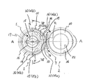
図1は、上蓋が開栓されている状態での本発明の複合容器蓋(ヒンジキャップ)の上面平面図であり、
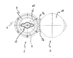
図2は、図1のヒンジキャップのA−A断面図であり、
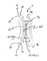
図3は、図1のヒンジキャップの底面図であり、
図4は、図1のヒンジキャップにおいて、筒状側壁と上蓋とのヒンジ接続部を拡大して示す上面平面図であり、
図5は、図1のヒンジキャップにおいて、ヒンジ接続部における外側壁の内面を透視して示す拡大正面図であり、
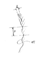
図6は、図4に示されている波形面を拡大して示す図であり、
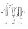
図7は、本発明において、筒状側壁に形成される二重壁構造のパターンの概略を示す側断面図である。
【0013】
図1乃至図4において、本発明の複合容器蓋の一例であるこのヒンジキャップは、キャップ本体1と上蓋2とから成っており、それ自体公知の合成樹脂、例えば、ポリエチレン、アイソタクティクポリプロピレン、エチレン−ポリプロピレン共重合体、ポリブテン−1、エチレン−ブテン−1共重合体、プロピレン−ブテン−1共重合体、エチレン−酢酸ビニル共重合体等のオレフィン系樹脂や、ポリスチレン、スチレン−ブタジエン共重合体、ABS樹脂或いはポリカーボネート等の一体成形によって、図2に示されているように、上蓋2が開栓された状態で成形される。
【0014】
キャップ本体1は、頂板部5と、頂板部5の周縁部から垂下している筒状側壁6とから成っており、上蓋2は、筒状側壁6の上端部分にヒンジ連結(ヒンジ接続部7)されている。図2及びヒンジ接続部7を拡大して示す図4に明瞭に示されている様に、このヒンジ接続部7において、上蓋2は、周方向に間隔を置いて設けられている一対のヒンジ連結バンド7a,7bにより筒状側壁6の上端より若干下方に連結され、且つ該バンド7a,7bの間に設けられているヒンジ連結バンド7cによって、筒状側壁6の上端に連結されている。このように筒状側壁6にヒンジ連結されている上蓋2を旋回することにより、キャップ本体1の頂板部5は完全に覆われるようになっている。
【0015】
キャップ本体1の筒状側壁6の内面には、アンダーカット8が形成されており、また、頂板部5の内面の周縁部分には、筒状側壁6とは間隔を置いて下方に延びているインナーリング9が形成されている。即ち、このインナーリング9と筒状側壁6との間の空間に容器口部(図示せず)が嵌め込まれ、且つアンダーカット8と容器口部の外面との係合により、キャップ本体1は、容器口部にしっかりと固定されるものである。
【0016】
キャップ本体1の頂板部5には、注出用開口を形成するためのスコア15が形成されており、且つ頂板部5の外面には、スコア破断用のタブリング16が設けられており、このタブリング16を引っ張り上げることにより、スコア15が破断し、頂板部5に注出用の開口が形成されるようになっている。
また、頂板部5の外面には、スコア15を取り囲むようにして、注出用筒17が設けられており、スコア15の破断によって形成された注出用開口を通り、この注出用筒17に沿って、容器内容液が注ぎ出される。尚、図2から明らかな通り、注出筒17のヒンジ接続部7側は、上蓋2の旋回を阻害しないように、背が低く形成されている。
更に、頂板部5の外面には、上記の注出用筒17の外側に、比較的背の低い上蓋係止用周状突起18が形成されている。
【0017】
一方、上蓋2は、天板20と、天板20の周縁部から延びているスカート21とから形成されており、天板20の内面には、シール用の周状突起22が形成されている。即ち、上蓋2を閉じた時、この周状突起22の外面が注出用筒17の内面に密着するようになっており、この密着により、注出用開口を形成した後のシール性が確保される。
尚、上記で述べた様に、注出用筒17のヒンジ接続部7側は、背が低く形成されているため、上蓋2を旋回して閉じる際に、上蓋2の周状突起22の旋回が注出用筒17により阻害されないようになっている。
更に、スカート21の先端部内面には、凹部26が周状に形成されている。即ち、上蓋2を閉じた時、この凹部26が、頂板部5の外面に設けられている上蓋係止用周状突起18と係合し、これにより、上蓋2の閉栓状態が保持される。
【0018】
上述したヒンジキャップにおいては、筒状側壁6は、弧状スリット30及び弧状スリット30の両端から延びている補助スリット31によって、外側壁35と内側壁36とに分断されており、特に図1から明らかな通り、筒状側壁6の約半周が二重壁構造領域Wとなっている。添付図面では、この弧状スリット30により分断されている外側壁及び内側壁を、それぞれ、35a及び36aで示し、補助スリット31により分断されている外側壁及び内側壁を、それぞれ、35b及び36bで示した。
【0019】
上記のスリットの内、弧状スリット30は、ヒンジ接続部7に対応して形成されているものであり、その周方向両端部は、それぞれ、ヒンジ接続部7の周方向両端部の近傍(ヒンジ連結バンド7a,7bの近傍)に位置している(図1参照)。また、弧状スリット30は、筒状側壁6の上端から下端近傍にまで延びており、従って、ヒンジ接続部7において、外側壁35aと内側壁36aとは、下端の連結部37で一体に連なっている。
また、弧状スリット30により分断された外側壁35aの周方向両端部分には、上端から筒状側壁6の下端或いは下端近傍にまで延びているスコア38、38が形成されており、更に、内側壁36aの周方向両端部分には、下端から筒状側壁6の上方に向かって延びているスコア39、39が形成されている。従って、内側壁36aに形成されているスコア39は、外側壁35aに形成されているスコア38に対面しており、更に弧状スリット30は、一対のスコア38,38或いは39,39の間に位置し、これらのスコア38,39は、弧状スリット30と補助スリット31との境界部に位置している。
また、弧状スリット30の周方向両端部から周方向に延びている補助スリット31は、筒状側壁6の下端にまで延びており、この補助スリット31によって、外側壁35bと内側壁36bとは、完全に分断されていることが好ましいが、補助スリット31を、筒状側壁6の上端から下端近傍にまで延びていてもよい。尚、図3では、補助スリット31の下端は省略している。
【0020】
上述した構造のヒンジキャップでは、上蓋2を開栓した状態で引き降ろすことにより、ヒンジ接続部7での外側壁35aを弧状スリット30の周方向両端部に位置するスコア38,38に沿って容易に引裂くことができる。更に、引裂かれた外側壁35aを上方に引っ張り上げることにより、スコア39,39に沿って内側壁36aを容易に引裂くことができる。これに加えて、前述した補助スリット31が形成されているため、更に外側壁35aを上方に引っ張り上げることにより、キャップ本体1を容易に容器口部から取り外すことができる。かくして、上述した構造のヒンジキャップは、極めて優れた分別廃棄性を示す。
【0021】
尚、上記の補助スリット31は、筒状側壁6のヒンジ接続部7以外の部分全体に設けることもできるが、この場合には、ヒンジ接続部7とは反対側の容器内容液が注ぎ出される部分にも補助スリット31が形成されることになり、注ぎ出された液が補助スリット31内に浸入してしまうおそれがある。従って、弧状スリット30と補助スリット31との合計の周方向長さは、筒状側壁の周方向長さ(全周)の20乃至60%程度とするのが好適である。
また、筒状側壁6の内面に形成されているアンダーカット8には、一定間隔で切り欠き40を設けることができ、これにより、キャップ本体1の容器口部からの取り外しを容易に行うことができる。この場合、上記のスコア38、39に対応する位置に、このような切り欠き40を形成しておくのがよい。即ち、スコア39に沿っての内側壁36aの引裂きを容易に行い、その捲り上げを一層容易に行うためである。
【0022】
かかるヒンジキャップにおいて、ヒンジ接続部7における外側壁35aの内面を透視して示す図5及び図6のヒンジ接続部の拡大上面図に示されているように、外側壁35aの内面には、周方向への凹凸の繰り返しによる波形面45が上端から下端の全面にわたって形成されている。
本発明においては、このような波形面45を形成することにより、成形時の金型ツールの破損や変形を有効に防止することが可能となり、キャップの成形性を向上させることができる。
【0023】
上述したヒンジキャップは、図1乃至図3に示されているような上蓋2を開栓した状態で成形される。
即ち、上蓋を開放した状態のキャップ形状に金型が配置され、キャップ本体1を形成する金型の中央部分(例えば図2において、Xで示す位置)に射出ゲートが配置され、この射出ゲートから、キャップを構成する樹脂の溶融物が射出され、射出された樹脂溶融物は、キャップ本体1を形成する金型空間内に流れ、次いで、上蓋2を形成する空間内に流れ、これにより、目的とする形状(上蓋が開放された形状)のヒンジキャップが成形される。
かかる成形に際しては、金型内に射出された溶融樹脂は、スリット形成用ツールによって形成される外側壁35形成用空間及び内側壁36形成用空間内に流れ込むが、これらの空間は非常に狭いため、樹脂の流れ込みにより、高い樹脂圧が発生する。この場合、上蓋2を形成する空間内に流れ込む多量の溶融樹脂は、ヒンジ接続部7における外側壁35a形成用の空間を通過するため、多量の溶融樹脂の通過により、外側壁35a形成用の空間では、著しく高い樹脂圧が発生する。しかも、これらの空間を形成するスリット形成用ツールは、非常に薄く、強度の低いものであるため、上記の樹脂圧によって破損や変形等を生じ易く、特に弧状スリット30形成用金型ツールには、外側壁35a形成用の空間で発生する著しく高い樹脂圧が加わるため、破損や変形が極めて生じ易くなっている。
【0024】
しかるに、本発明にしたがって、外側壁35aの内面に波形面45を形成することにより、弧状スリット30には、それに対応する波形面が形成される。即ち、成形時に用いる弧状スリット30形成用の金型ツールは、このような波形面を有しているため、部分的に肉厚の部分を有しており、その強度は高められている。しかも、外側壁35a形成用の空間で発生する著しく高い樹脂圧は、この金型ツールの波形面で分散される。従って、波形面45によるツールの強度向上効果及び樹脂圧分散効果によって、著しく高い樹脂圧が加わる弧状スリット30形成用の金型ツールの破損や変形を有効に防止することができ、成形性を向上させることが可能となるものである。
【0025】
尚、上述した例においては、ヒンジ接続部7における外側壁35aの内面にのみ波形面45が形成されているが、勿論、ヒンジ接続部7以外の領域の外側壁35bの内面にも波形面45を形成することもできるし、また、成形後の型抜きが阻害されない限り、内側壁36a或いは36bの外面(外側壁35a或いは35bに対面する側の面)にも、波形面45を形成することができる。
【0026】
また、上述した波形面45を拡大して示す図6を参照して、この波形面45のピッチp(隣り合う凸部同士或いは凹部同士の間隔)は、2.0乃至3.5mmの範囲にあることが好ましく、また、凹部と凸部との高低差hは、0.2乃至0.35mmの範囲にあることが好ましい。即ち、ピッチpが上記範囲外であるときは、波形面45による強度向上効果や樹脂圧分散効果が不十分となり、また、高低差hは、筒状側壁6の厚みによって制限されるため、上記範囲より大きくすることが困難となり、また高低差hが上記範囲よりも小さいと、波形面45による強度向上効果や樹脂圧分散効果が不十分となるからである。
【0027】
上述した本発明は、ヒンジキャップを例にとって説明したが、ヒンジキャップに限定されるものではなく、キャップ本体の筒状側壁に二重壁構造が形成されている限り、上蓋が螺子式のキャップにも本発明を適用し得ることは当然である。
また、筒状側壁に形成される二重壁構造のパターンとしては、図7に示すものが挙げられる。図7のパターンは概略であり、内側壁に形成されるアンダーカット等は省略している。
即ち、図7(a)に示すように、スリット50によって分断された外側壁51と内側壁52とが下端で連なっているパターン、図7(b)に示すように、スリット50によって外側壁51と内側壁52とが完全に分断されているパターン、及び図7(c)に示すように、スリット50によって分断された外側壁51と内側壁52とが上端で連なっているパターンの二重壁構造がキャップ本体の筒状側壁に形成し得るが、本発明は、これら何れのパターンの二重壁構造にも適用することができる。即ち、キャップ本体の構造等に応じて、樹脂圧によるスリット形成用ツールの破損や変形を生じ易い部分において、その外側壁51の内面或いは内側壁52の外面に、前述した波形面を形成することにより、スリット形成用ツールの破損や変形を有効に防止することができ、成形性を向上させることができる。
【0028】
【発明の効果】
本発明によれば、筒状側壁がスリットにより外側壁と内側壁とに分断された二重壁構造を有するキャップ本体を備えた複合容器蓋において、外側壁の内面或いは内側壁の外面に、周方向への凹凸の繰り返しによる波形面を形成することにより、スリット形成用金型ツールの強度を高め且つ成形時に該ツールに加わる樹脂圧を分散させることができ、成形時の該ツールの破損や変形等を有効に防止し、成形性を高めることができる。
【図面の簡単な説明】
【図1】上蓋が開栓されている状態での本発明の複合容器蓋(ヒンジキャップ)の上面平面図。
【図2】図1のヒンジキャップのA−A断面図。
【図3】図1のヒンジキャップの底面図。
【図4】図1のヒンジキャップにおいて、筒状側壁と上蓋とのヒンジ接続部を拡大して示す上面平面図。
【図5】図1のヒンジキャップにおいて、ヒンジ接続部における外側壁の内面を透視して示す拡大正面図。
【図6】図4に示されている波形面を拡大して示す図。
【図7】本発明において、筒状側壁に形成される二重壁構造のパターンの概略を示す側断面図。
【符号の説明】
1:キャップ本体
2:上蓋
5:頂板部
6:筒状側壁
7:ヒンジ接続部
8:アンダーカット
30:弧状スリット
31:補助スリット
35:外側壁
36:内側壁
45:波形面[0001]
BACKGROUND OF THE INVENTION
The present invention relates to a composite container lid comprising a cap body fitted and fixed to a container mouth portion, and an upper lid provided so as to cover the cap body. More specifically, the present invention relates to at least a cylindrical side wall of the cap body. The present invention relates to a composite container lid of which a part has a double wall structure of an outer wall and an inner wall.
[0002]
[Prior art]
A composite container lid including a cap main body fitted and fixed to the container mouth portion and an upper lid provided so as to cover the cap main body is widely used in various containers such as various seasoning containers. Roughly speaking, such a composite container lid has a so-called hinge type (hinge cap) in which the upper lid is hinged to the cap body, and a so-called screw type in which the upper lid is detachably provided on the cap body by screw fastening. It is classified as a thing (screw cap).
In the composite container lid as described above, in any type of hinge cap and screw cap, the cap body is formed from a top plate portion and a cylindrical side wall extending downward from the periphery of the top plate portion, The cap main body is fixed to the container mouth by fitting the container mouth into the cylindrical side wall.
[0003]
By the way, as such a composite container lid, what has the double wall structure of an outer wall and an inner wall is known by the slit at least one part of the circumferential direction of the cylindrical side wall of a cap main body. The slit extends downward from the upper end of the cylindrical side wall or upward from the lower end, and the outer wall and the inner wall separated by the slit are connected to each other at the upper end or the lower end in at least a part of the circumferential direction. ing.
Recently, there has been a demand for separate disposal of waste from the standpoint of waste disposal processing, resource reuse, etc., and separate disposal of container lids made of materials different from containers is also required. However, the cap body fitted and fixed to the container mouth has the disadvantage that the work for removing it from the container mouth is very troublesome and the waste for separation is extremely insufficient. Yes. However, one of the advantages of the composite container lid provided with the cap body having the double wall structure described above is excellent separation and disposal. That is, since at least a part of the cylindrical side wall is divided into an outer wall and an inner wall, the thickness of the outer wall and the inner wall is thinner than that of a normal cylindrical side wall, and the outer wall can be easily formed. It can be torn, and after tearing the outer wall, the inner wall can be easily rolled up, and this work has the advantage that the cap body can be easily removed from the container mouth. .
[0004]
For example, as an example of a composite container lid provided with a cap body having a double wall structure, Japanese Patent Application Laid-Open No. 2000-142758,
“A cap body having a top plate portion and a cylindrical side wall depending from the periphery of the top plate portion, and an upper lid hinged to the upper end portion of the cylindrical side wall of the cap body. In the hinge cap in which an engagement projection that can engage with the outer surface of the container mouth is formed, and the container mouth is fitted into the cylindrical side wall so that the cap body is attached to the container mouth.
In the thickness part of the cylindrical side wall where the hinge connection part with the upper lid is formed, a slit extending downward from the upper end thereof is formed deeply to the vicinity of the lower end of the cylindrical side wall. The cylindrical side wall of the hinge connection part is divided into an inner side wall and an outer side wall,
At both ends of the hinge connecting portion, a first score is formed on the outer wall along both ends of the slit, and a second score is formed on at least the inner wall so as to face the first score. A hinge cap that is engraved on the engaging protrusion. "
Is disclosed.
[0005]
In the hinge cap disclosed in this prior art, the first cap formed at both ends of the hinge connection portion is obtained by pulling down the used cap with the hand while holding the upper lid with the upper lid open. The outer wall is torn along the score. Since the torn outer wall is connected to the inner wall at the lower end, the inner wall is torn along the second score by pulling the outer wall upward for each upper lid. Thus, since the engagement between the cylindrical side wall and the container mouth portion is released at the portion where the outer wall and the inner side wall are torn, the cap body can be easily attached to the container mouth without using a special tool. It can be removed from the part.
[0006]
[Problems to be solved by the invention]
However, as represented by the above prior art, a cap body in which a double wall structure divided into an inner wall and an outer wall is formed on at least a part of the cylindrical side wall is problematic in terms of formability. have. In other words, the cap body as described above is formed by injecting molten resin into a mold having a predetermined shape, and the cylindrical side wall is divided into an outer wall and an inner wall to be doubled. Since a slit for forming a wall structure is formed, a mold tool having a shape corresponding to the slit is used for molding, and a very narrow outer wall space and inner wall formed by the mold tool are used. The molten resin flows into the working space, and as a result, resin pressure is applied to the mold tool. However, since this mold tool has a shape corresponding to the slit, it is itself very thin and low in strength. Therefore, the resin pressure at the time of molding as described above is liable to cause breakage and deformation of the slit forming mold tool, and there is a problem that molding failure is liable to occur due to such breakage and deformation of the tool. .
[0007]
Accordingly, an object of the present invention is to provide a slit forming metal for molding in a composite container lid having a cap body having a double wall structure in which at least a part of a cylindrical side wall is divided into an inner side wall and an outer side wall. It is an object of the present invention to provide a composite container lid in which breakage and deformation of a mold tool are effectively suppressed and formability is improved.
[0008]
[Means for Solving the Problems]
According to the present invention, it comprises a cap body made of synthetic resin fitted and fixed to the container mouth portion, and an upper lid that is provided so as to cover the cap body and is formed by integral molding with the cap body .
The cap body is formed of a top plate portion and a cylindrical side wall extending downward from the periphery of the top plate portion, and at least a partial region in the circumferential direction of the cylindrical side wall is divided into an inner side wall and an outer side wall. The inner wall and the outer wall are connected at the lower end or the upper end at least in a circumferential portion, and the upper lid is connected to the upper end portion of the outer surface of the outer wall. In the hinged composite container lid,
The inner surface of the outer wall is a corrugated surface in which at least a part in the circumferential direction is formed by repeating irregularities in the circumferential direction,
In the double wall structure region of the cylindrical side wall, the corrugated surface is formed on the inner surface of the outer wall corresponding to the arc-shaped slit dividing the outer wall and the inner wall in the hinge connection portion, and the outer surface of the outer wall is at least cylindrical. A composite container lid is provided that forms part of the surface .
In addition, according to the present invention, the cap main body includes a cap main body that is fitted and fixed to the container mouth portion, and an upper lid that is provided so as to cover the cap main body. And at least a partial region in the circumferential direction of the cylindrical side wall has a double wall structure divided into an inner side wall and an outer side wall, and the inner side wall And the outer wall is a composite container lid that is connected at least at a part in the circumferential direction at the lower end or the upper end, and the inner surface of the outer wall or the outer surface of the inner wall is at least partially in the circumferential direction. It is a corrugated surface that is formed by repeating irregularities on
The corrugated surface has a pitch of 2.0 to 3.5 mm and a height difference of 0.2 to 0.35 mm. A composite container lid is provided.
[0009]
In the present invention, in the double wall structure region formed on the cylindrical side wall of the cap body, a corrugated surface is formed on the inner surface of the outer wall or the outer surface of the inner wall by repeating irregularities in the circumferential direction. It is an important feature.
That is, when such a corrugated surface is formed on the inner surface of the outer wall or the outer surface of the inner wall, a slit for dividing the cylindrical side wall into the outer wall and the inner wall at the portion where the corrugated surface is formed. Has a corrugated shape corresponding thereto. Accordingly, the slit forming die tool used at the time of molding also has a corrugated surface, and its strength increases. Further, at the time of molding, the resin pressure applied to the tool when molten resin flows into the outer wall space or the inner wall space formed by such a mold tool is dispersed by such a corrugated surface. . Therefore, according to the present invention, damage or deformation of the slit forming mold tool at the time of molding is effectively prevented by the effect of increasing the strength of the slit forming mold tool by the corrugated surface and the resin pressure dispersion effect at the time of molding, Excellent moldability can be ensured.
[0010]
The present invention also provides a hinge cap in which the upper lid is hinged to the cap body as long as it has a double wall structure in which at least a part of the cylindrical side wall is divided into an outer wall and an inner wall. Also, the present invention can be applied to a screw cap in which the upper lid is screwed to the cap body, but has the greatest effect when applied to a hinge cap.
That is, in the hinge cap, the upper lid is hinged to the upper end portion of the cylindrical side wall of the cap body. Therefore, when the cylindrical side wall is divided into the outer wall and the inner side wall, the upper end portion of the outer wall. The top lid is hinged. Molding of such a hinge cap is performed by injecting molten resin from the central part of the mold that forms the cap body, with the mold placed in the shape of a cap with the top lid open, and the injected melt When the resin reaches the mold space that forms the cap body, or passes through the outer wall and a large amount of molten resin flows into the mold space that forms the upper lid, the target shape (the upper lid is opened) (Hinge shape) hinge cap. As understood from this, since a large amount of molten resin flows to form the upper lid on the thin outer wall, the resin pressure applied to the slit forming mold tool is extremely high, and the tool is damaged or deformed. Such troubles tend to occur considerably more frequently than screw caps (the upper lid is molded separately from the cap body). In the present invention, the above-described corrugated surface is formed on the inner surface of the outer wall, so that the problem relating to the moldability of the hinge cap can be effectively solved.
[0011]
Further, in the present invention, the corrugated surface described above may be formed on the entire inner surface of the outer wall or the entire outer surface of the inner wall. However, a resin pressure applied to a part of the circumferential direction, for example, a slit forming mold tool. It is also possible to form a corrugated surface only in the highest part. Specifically, in the above-described hinge cap, the corrugated surface can be formed only on the inner surface of the outer wall of the portion where the upper lid is hinge-connected.
Of course, the corrugated surface can be formed on both the outer wall and the inner wall, or can be formed only on the outer surface of the inner wall.
[0012]
DETAILED DESCRIPTION OF THE INVENTION
Hereinafter, the present invention will be described in detail with reference to the accompanying drawings, taking as an example a hinge cap to which the present invention is most suitably applied.
FIG. 1 is a top plan view of a composite container lid (hinge cap) of the present invention in a state where an upper lid is opened;
2 is a cross-sectional view of the hinge cap of FIG.
FIG. 3 is a bottom view of the hinge cap of FIG.
4 is an enlarged top plan view showing a hinge connection portion between the cylindrical side wall and the upper lid in the hinge cap of FIG.
FIG. 5 is an enlarged front view of the hinge cap of FIG.
FIG. 6 is an enlarged view of the corrugated surface shown in FIG.
FIG. 7 is a side cross-sectional view schematically showing a pattern of a double wall structure formed on a cylindrical side wall in the present invention.
[0013]
1 to 4, this hinge cap, which is an example of the composite container lid of the present invention, comprises a
[0014]
The
[0015]
An undercut 8 is formed on the inner surface of the
[0016]
The
Further, a pour
Further, on the outer surface of the
[0017]
On the other hand, the
As described above, since the
Furthermore, a
[0018]
In the hinge cap described above, the
[0019]
Among the above slits, the arc-shaped
In addition, scores 38, 38 extending from the upper end to the lower end of the
Further, the auxiliary slit 31 extending in the circumferential direction from both circumferential ends of the arc-shaped
[0020]
In the hinge cap having the above-described structure, the
[0021]
The auxiliary slit 31 can be provided in the entire portion of the
Further, the undercut 8 formed on the inner surface of the
[0022]
In such a hinge cap, the inner surface of the
In the present invention, by forming such a
[0023]
The above-described hinge cap is formed in a state where the
That is, the mold is arranged in a cap shape with the upper lid opened, and an injection gate is arranged in the central portion of the mold forming the cap body 1 (for example, a position indicated by X in FIG. 2). The melt of the resin constituting the cap is injected, and the injected resin melt flows into the mold space that forms the
In such molding, the molten resin injected into the mold flows into the
[0024]
However, according to the present invention, by forming the
[0025]
In the above-described example, the
[0026]
Further, referring to FIG. 6 showing the
[0027]
The present invention described above has been described by taking the hinge cap as an example. However, the present invention is not limited to the hinge cap, and as long as the double wall structure is formed on the cylindrical side wall of the cap body, the upper lid is a screw type cap. Of course, the present invention can also be applied.
Moreover, what is shown in FIG. 7 is mentioned as a pattern of the double wall structure formed in a cylindrical side wall. The pattern in FIG. 7 is schematic and an undercut or the like formed on the inner wall is omitted.
That is, as shown in FIG. 7A, a pattern in which the
[0028]
【The invention's effect】
According to the present invention, in a composite container lid having a cap body having a double wall structure in which a cylindrical side wall is divided into an outer wall and an inner wall by a slit, an inner surface of the outer wall or an outer surface of the inner wall By forming a corrugated surface by repeating irregularities in the direction, it is possible to increase the strength of the mold tool for slit formation and disperse the resin pressure applied to the tool during molding, and damage or deformation of the tool during molding Etc. can be effectively prevented and the moldability can be improved.
[Brief description of the drawings]
FIG. 1 is a top plan view of a composite container lid (hinge cap) of the present invention in a state where an upper lid is opened.
2 is a cross-sectional view of the hinge cap of FIG. 1 along AA.
3 is a bottom view of the hinge cap of FIG. 1. FIG.
4 is an enlarged top plan view showing a hinge connection portion between a cylindrical side wall and an upper lid in the hinge cap of FIG. 1. FIG.
5 is an enlarged front view showing the inner surface of the outer wall of the hinge connection portion as seen through in the hinge cap of FIG. 1;
6 is an enlarged view showing the waveform surface shown in FIG. 4;
FIG. 7 is a side sectional view schematically showing a pattern of a double wall structure formed on a cylindrical side wall in the present invention.
[Explanation of symbols]
1: Cap body 2: Top lid 5: Top plate part 6: Cylindrical side wall 7: Hinge connecting part 8: Undercut 30: Arc-shaped slit 31: Auxiliary slit 35: Outer wall 36: Inner side wall 45: Corrugated surface
Claims (4)
前記キャップ本体は、頂板部と、頂板部の周縁から下方に延びている筒状側壁とから形成され、該筒状側壁における周方向の少なくとも一部の領域は、内側壁と外側壁とに分断された二重壁構造を有しており、該内側壁と外側壁とは、少なくとも一部の周方向部分で、下端又は上端で連結され、前記上蓋は、前記外側壁の外面の上端部分にヒンジ接続されている複合容器蓋において、
前記外側壁の内面は、周方向の少なくとも一部分が、周方向への凹凸の繰り返しにより形成されている波形面であり、
前記筒状側壁の二重壁構造領域において、前記ヒンジ接続部における前記外側壁と内側壁とに分断する弧状スリットに対応する外側壁の内面に前記波形面が形成され、外側壁の外面は少なくとも円筒面の一部を形成していることを特徴とする複合容器蓋。 A cap body made of synthetic resin fitted and fixed to the container mouth, and an upper lid that is provided so as to cover the cap body and is formed by integral molding with the cap body ,
The cap body is formed of a top plate portion and a cylindrical side wall extending downward from the periphery of the top plate portion, and at least a partial region in the circumferential direction of the cylindrical side wall is divided into an inner side wall and an outer side wall. The inner wall and the outer wall are connected at the lower end or the upper end at least in a circumferential portion, and the upper lid is connected to the upper end portion of the outer surface of the outer wall. In the hinged composite container lid,
The inner surface of the outer wall is a corrugated surface in which at least a part in the circumferential direction is formed by repeating irregularities in the circumferential direction,
In the double wall structure region of the cylindrical side wall, the corrugated surface is formed on the inner surface of the outer wall corresponding to the arc-shaped slit dividing the outer wall and the inner wall in the hinge connection portion, and the outer surface of the outer wall is at least A composite container lid characterized by forming a part of a cylindrical surface .
前記波形面は、ピッチが2.0乃至3.5mm、高低差が0.2乃至0.35mmである、
ことを特徴とする複合容器蓋。A cap body fitted and fixed to the container mouth portion, and an upper lid provided so as to cover the cap body. The cap body includes a top plate portion and a cylindrical side wall extending downward from the periphery of the top plate portion. And at least a portion of the cylindrical side wall in the circumferential direction has a double wall structure divided into an inner wall and an outer wall, and the inner wall and the outer wall have at least one In the composite container lid connected at the lower end or the upper end at the circumferential portion of the part, at least a part of the inner surface of the outer wall or the outer surface of the inner wall is formed by repeating unevenness in the circumferential direction. It is a corrugated surface,
The corrugated surface has a pitch of 2.0 to 3.5 mm and a height difference of 0.2 to 0.35 mm.
A composite container lid.
Priority Applications (1)
| Application Number | Priority Date | Filing Date | Title |
|---|---|---|---|
| JP2001140368A JP4792168B2 (en) | 2001-05-10 | 2001-05-10 | Composite container lid |
Applications Claiming Priority (1)
| Application Number | Priority Date | Filing Date | Title |
|---|---|---|---|
| JP2001140368A JP4792168B2 (en) | 2001-05-10 | 2001-05-10 | Composite container lid |
Publications (2)
| Publication Number | Publication Date |
|---|---|
| JP2002337909A JP2002337909A (en) | 2002-11-27 |
| JP4792168B2 true JP4792168B2 (en) | 2011-10-12 |
Family
ID=18986983
Family Applications (1)
| Application Number | Title | Priority Date | Filing Date |
|---|---|---|---|
| JP2001140368A Expired - Lifetime JP4792168B2 (en) | 2001-05-10 | 2001-05-10 | Composite container lid |
Country Status (1)
| Country | Link |
|---|---|
| JP (1) | JP4792168B2 (en) |
Families Citing this family (6)
| Publication number | Priority date | Publication date | Assignee | Title |
|---|---|---|---|---|
| JP4722678B2 (en) * | 2005-11-10 | 2011-07-13 | 三笠産業株式会社 | Hinge cap |
| JP4762780B2 (en) * | 2006-05-11 | 2011-08-31 | 日本クラウンコルク株式会社 | Cap for good separation and disposal |
| JP5269487B2 (en) * | 2008-05-30 | 2013-08-21 | 株式会社吉野工業所 | Hinge cap |
| JP5202189B2 (en) * | 2008-08-28 | 2013-06-05 | 日本クラウンコルク株式会社 | Synthetic resin stopper cap with excellent separation and disposal |
| JP5321825B2 (en) * | 2009-07-10 | 2013-10-23 | 東京ライト工業株式会社 | Cap separable from container mouth |
| JP5714322B2 (en) * | 2010-12-27 | 2015-05-07 | 日本クロージャー株式会社 | Mold assembly for injection molding of synthetic resin container lids |
Family Cites Families (3)
| Publication number | Priority date | Publication date | Assignee | Title |
|---|---|---|---|---|
| JPH10119999A (en) * | 1996-10-18 | 1998-05-12 | Tenryu Kagaku Kogyo Kk | Pilfer-proof cap |
| JP4349668B2 (en) * | 1998-08-27 | 2009-10-21 | 日本クラウンコルク株式会社 | Hinge cap with excellent separation and disposal |
| JP3603935B2 (en) * | 1998-11-11 | 2004-12-22 | 日本クラウンコルク株式会社 | Hinge cap with good separation and disposal |
-
2001
- 2001-05-10 JP JP2001140368A patent/JP4792168B2/en not_active Expired - Lifetime
Also Published As
| Publication number | Publication date |
|---|---|
| JP2002337909A (en) | 2002-11-27 |
Similar Documents
| Publication | Publication Date | Title |
|---|---|---|
| US6016931A (en) | Cap separable from bottle at the time of disposal | |
| JP5038787B2 (en) | cap | |
| JP4792168B2 (en) | Composite container lid | |
| US4480761A (en) | Tamper indicating closure for a container | |
| JP4616505B2 (en) | Hinge cap | |
| JP3603935B2 (en) | Hinge cap with good separation and disposal | |
| JP5362440B2 (en) | Hinge cap | |
| JP4222801B2 (en) | Hinge cap with tamper evidence added to the top lid | |
| JP4057274B2 (en) | Plastic container lid | |
| JP3895704B2 (en) | Plastic cap with extraction tube | |
| JP4156265B2 (en) | Cap with excellent opening and flow control | |
| JP4575590B2 (en) | Resin cap | |
| JP4156055B2 (en) | Hinge cap with excellent separation and disposal | |
| JP4349668B2 (en) | Hinge cap with excellent separation and disposal | |
| JP4330186B2 (en) | Cap with excellent separation and disposal | |
| JP4330187B2 (en) | Hinge cap with excellent separation and disposal | |
| JP3956345B2 (en) | Composite container lid | |
| JP4420301B2 (en) | Plastic cap with stopper mounting type | |
| WO2006070656A1 (en) | Hinge cap | |
| JP4500626B2 (en) | Plastic cap | |
| JP2003002348A (en) | Synthetic resin made container lid | |
| JP4672938B2 (en) | Composite container lid | |
| JP4460710B2 (en) | Resin cap with excellent separation and disposal | |
| JP4621419B2 (en) | Hinge cap | |
| JP4762780B2 (en) | Cap for good separation and disposal |
Legal Events
| Date | Code | Title | Description |
|---|---|---|---|
| A621 | Written request for application examination |
Free format text: JAPANESE INTERMEDIATE CODE: A621 Effective date: 20080219 |
|
| A977 | Report on retrieval |
Free format text: JAPANESE INTERMEDIATE CODE: A971007 Effective date: 20100813 |
|
| A131 | Notification of reasons for refusal |
Free format text: JAPANESE INTERMEDIATE CODE: A131 Effective date: 20100824 |
|
| A521 | Written amendment |
Free format text: JAPANESE INTERMEDIATE CODE: A523 Effective date: 20101025 |
|
| A131 | Notification of reasons for refusal |
Free format text: JAPANESE INTERMEDIATE CODE: A131 Effective date: 20110412 |
|
| A521 | Written amendment |
Free format text: JAPANESE INTERMEDIATE CODE: A523 Effective date: 20110610 |
|
| TRDD | Decision of grant or rejection written | ||
| A01 | Written decision to grant a patent or to grant a registration (utility model) |
Free format text: JAPANESE INTERMEDIATE CODE: A01 Effective date: 20110705 |
|
| A01 | Written decision to grant a patent or to grant a registration (utility model) |
Free format text: JAPANESE INTERMEDIATE CODE: A01 |
|
| A61 | First payment of annual fees (during grant procedure) |
Free format text: JAPANESE INTERMEDIATE CODE: A61 Effective date: 20110725 |
|
| FPAY | Renewal fee payment (event date is renewal date of database) |
Free format text: PAYMENT UNTIL: 20140729 Year of fee payment: 3 |
|
| R150 | Certificate of patent or registration of utility model |
Ref document number: 4792168 Country of ref document: JP Free format text: JAPANESE INTERMEDIATE CODE: R150 Free format text: JAPANESE INTERMEDIATE CODE: R150 |
|
| EXPY | Cancellation because of completion of term |