JP4792121B2 - Belt unit and image forming apparatus - Google Patents
Belt unit and image forming apparatus Download PDFInfo
- Publication number
- JP4792121B2 JP4792121B2 JP2010195311A JP2010195311A JP4792121B2 JP 4792121 B2 JP4792121 B2 JP 4792121B2 JP 2010195311 A JP2010195311 A JP 2010195311A JP 2010195311 A JP2010195311 A JP 2010195311A JP 4792121 B2 JP4792121 B2 JP 4792121B2
- Authority
- JP
- Japan
- Prior art keywords
- belt
- state
- belt unit
- unit
- transfer
- Prior art date
- Legal status (The legal status is an assumption and is not a legal conclusion. Google has not performed a legal analysis and makes no representation as to the accuracy of the status listed.)
- Active
Links
- 238000010586 diagram Methods 0.000 description 17
- 238000004804 winding Methods 0.000 description 13
- 238000000034 method Methods 0.000 description 11
- 238000003780 insertion Methods 0.000 description 10
- 230000037431 insertion Effects 0.000 description 10
- 230000008569 process Effects 0.000 description 9
- 238000004519 manufacturing process Methods 0.000 description 6
- 230000032258 transport Effects 0.000 description 6
- 238000004140 cleaning Methods 0.000 description 5
- 230000002542 deteriorative effect Effects 0.000 description 5
- 239000000463 material Substances 0.000 description 5
- 230000007246 mechanism Effects 0.000 description 4
- 239000011324 bead Substances 0.000 description 3
- 230000015572 biosynthetic process Effects 0.000 description 3
- 239000003086 colorant Substances 0.000 description 3
- 238000010438 heat treatment Methods 0.000 description 3
- 230000000694 effects Effects 0.000 description 2
- 239000011347 resin Substances 0.000 description 2
- 229920005989 resin Polymers 0.000 description 2
- 230000000717 retained effect Effects 0.000 description 2
- 239000000969 carrier Substances 0.000 description 1
- 238000005520 cutting process Methods 0.000 description 1
- 229910052736 halogen Inorganic materials 0.000 description 1
- 150000002367 halogens Chemical class 0.000 description 1
- 238000012986 modification Methods 0.000 description 1
- 230000004048 modification Effects 0.000 description 1
- 230000000630 rising effect Effects 0.000 description 1
- 238000007790 scraping Methods 0.000 description 1
- 238000000926 separation method Methods 0.000 description 1
Images


Landscapes
- Electrophotography Configuration And Component (AREA)
- Electrostatic Charge, Transfer And Separation In Electrography (AREA)
Description
本発明は、ベルトユニット及び画像形成装置に関するものである。 The present invention relates to a belt unit and an image forming apparatus.
従来、プリンタ、複写機、ファクシミリ装置、複合機等の画像形成装置、例えば、カラーのプリンタにおいては、感光体ドラムの表面が、帯電ローラによって帯電させられ、LEDヘッドによって露光されて静電潜像が形成され、該静電潜像に現像ローラ上で薄層化されたトナーが静電的に付着させられてトナー像が形成される。そして、該トナー像を用紙上に、転写ローラによって転写し、定着器によって定着させることによって、画像を形成することができる。また、転写後に前記感光体ドラム上に残留したトナーは、クリーニング装置によって除去される。 2. Description of the Related Art Conventionally, in an image forming apparatus such as a printer, a copying machine, a facsimile machine, or a multifunction machine, for example, a color printer, the surface of a photosensitive drum is charged by a charging roller, exposed by an LED head, and electrostatic latent And the toner thinned on the developing roller is electrostatically attached to the electrostatic latent image to form a toner image. Then, the toner image is transferred onto a sheet by a transfer roller and fixed by a fixing device, whereby an image can be formed. Further, toner remaining on the photosensitive drum after the transfer is removed by a cleaning device.
ところで、前記プリンタにおいては、各色のトナー像を形成するために、それぞれ画像形成ユニットが配設され、該各画像形成ユニットに沿って用紙が搬送されるようになっている。そのために、前記各画像形成ユニット間にわたってベルトユニットが配設される。該ベルトユニットは、ドライブローラ、アイドルローラ、及びドライブローラとアイドルローラとによって張設される転写ベルトを備え、前記ドライブローラを回転させることによって転写ベルトを走行させ、用紙を搬送するようになっている。なお、転写ベルトに張力、すなわち、テンションを加えるためにテンション機構が配設される(例えば、特許文献1参照。)。 By the way, in the printer, in order to form toner images of the respective colors, image forming units are provided, and paper is conveyed along the image forming units. For this purpose, a belt unit is disposed between the image forming units. The belt unit includes a drive roller, an idle roller, and a transfer belt stretched between the drive roller and the idle roller, and the transfer belt is driven by rotating the drive roller to convey paper. Yes. A tension mechanism is provided to apply tension, that is, tension to the transfer belt (see, for example, Patent Document 1).
しかしながら、前記従来のベルトユニットにおいては、転写ベルトが樹脂によって形成されている場合に、例えば、ベルトユニットの製造時における次工程待ち、出荷待ち等において、転写ベルトに一定のテンションが加えられた状態で長時間放置されると、転写ベルトに巻きぐせが形成されてしまう。特に、プリンタが高温下に置かれた場合に、転写ベルトの材質の許容応力(弾性限度)を超えて外力が加わったとき等においては、転写ベルトに伸びも発生してしまう。このような転写ベルトを使用して印刷を行った場合、巻きぐせ、伸び等によって印刷品位が低下してしまう。 However, in the conventional belt unit, when the transfer belt is formed of a resin, for example, a state in which a certain tension is applied to the transfer belt in the next process waiting for the belt unit, waiting for shipment, etc. If left untreated for a long time, a curl is formed on the transfer belt. In particular, when the printer is placed at a high temperature, when an external force is applied exceeding the allowable stress (elastic limit) of the material of the transfer belt, the transfer belt is also stretched. When printing is performed using such a transfer belt, the print quality is deteriorated due to winding or stretching.
本発明は、前記従来のベルトユニットの問題点を解決して、印刷品位が低下するのを防止することができるベルトユニット及び画像形成装置を提供することを目的とする。 It is an object of the present invention to provide a belt unit and an image forming apparatus that can solve the problems of the conventional belt unit and prevent the print quality from deteriorating.
そのために、本発明のベルトユニットにおいては、第1、第2のローラと、該第1、第2のローラ間に配設されたベルトと、前記第1のローラを支持する第1の支持部材と、前記第2のローラを支持する第2の支持部材と、前記第1、第2の支持部材間に配設され、第1、第2の支持部材間に付勢力を発生させる付勢部材と、前記第1の支持部材に対して揺動自在に配設されたロック部材とを有する。 Therefore, in the belt unit of the present invention, the first and second rollers, the belt disposed between the first and second rollers, and the first support member that supports the first roller. A second support member that supports the second roller; and a biasing member that is disposed between the first and second support members and generates a biasing force between the first and second support members. And a lock member disposed to be swingable with respect to the first support member.
そして、ベルトユニットは、前記付勢部材による付勢及びロック部材の係止に伴って、前記ベルトに所定の張力が加えられる第1の状態、及び前記所定の張力が加えられない第2の状態に保持される。 The belt unit includes a first state in which a predetermined tension is applied to the belt and a second state in which the predetermined tension is not applied in accordance with the urging by the urging member and the locking of the lock member. Retained.
本発明によれば、ベルトユニットにおいては、第1、第2のローラと、該第1、第2のローラ間に配設されたベルトと、前記第1のローラを支持する第1の支持部材と、前記第2のローラを支持する第2の支持部材と、前記第1、第2の支持部材間に配設され、第1、第2の支持部材間に付勢力を発生させる付勢部材と、前記第1の支持部材に対して揺動自在に配設されたロック部材とを有する。 According to the present invention, in the belt unit, the first and second rollers, the belt disposed between the first and second rollers, and the first support member that supports the first roller. A second support member that supports the second roller; and a biasing member that is disposed between the first and second support members and generates a biasing force between the first and second support members. And a lock member disposed to be swingable with respect to the first support member.
そして、ベルトユニットは、前記付勢部材による付勢及びロック部材の係止に伴って、前記ベルトに所定の張力が加えられる第1の状態、及び前記所定の張力が加えられない第2の状態に保持される。 The belt unit includes a first state in which a predetermined tension is applied to the belt and a second state in which the predetermined tension is not applied in accordance with the urging by the urging member and the locking of the lock member. Retained.
この場合、例えば、ベルトユニットの製造時における次工程待ち、出荷待ち等の間において、前記付勢部材の付勢力によって、前記ベルトに張力が加わらないようにすることができる。 In this case, for example, it is possible to prevent tension from being applied to the belt by the urging force of the urging member during waiting for the next process, waiting for shipment, etc. at the time of manufacturing the belt unit.
したがって、ベルトユニットが、製造時における次工程待ち、出荷待ち等において長時間放置された場合、高温下に置かれた場合等においても、ベルトに伸びが発生するのを防止することができ、ベルトに巻きぐせが形成されるのを防止することができる。また、ベルトの材質の許容応力(弾性限度)を超える外力が加わらないので、ベルトに伸びが発生するのを防止することができ、巻きぐせが形成されるのを防止することができる。その結果、印刷品位が低下するのを防止することができる。 Therefore, the belt unit can be prevented from stretching even when left for a long time in the next process, waiting for shipment, etc. at the time of manufacture or when it is placed at a high temperature. It is possible to prevent the wrapping from being formed. Further, since an external force exceeding the allowable stress (elastic limit) of the belt material is not applied, it is possible to prevent the belt from being stretched and to prevent the formation of winding. As a result, it is possible to prevent the print quality from deteriorating.
また、巻きぐせが形成されるのを防止することができるので、モノクロ印刷を行うときに、カラーの画像形成ユニットを退避させ、ブラックの画像形成ユニットだけで画像を形成するカラー画像装置において、用紙の印刷面と他の色の画像形成ユニットの下面とが擦れてしまうことがないので、印刷品位が低下するのを防止することができる。 In addition, since it is possible to prevent the formation of curling, in a color image apparatus that retracts a color image forming unit and forms an image only with a black image forming unit when performing monochrome printing, Since the print surface and the lower surface of the image forming unit of another color are not rubbed, it is possible to prevent the print quality from deteriorating.
以下、本発明の実施の形態について図面を参照しながら詳細に説明する。なお、この場合、画像形成装置としてのカラーのプリンタについて説明する。 Hereinafter, embodiments of the present invention will be described in detail with reference to the drawings. In this case, a color printer as an image forming apparatus will be described.
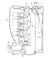
図2は本発明の第1の実施の形態におけるプリンタの概念図である。 FIG. 2 is a conceptual diagram of the printer according to the first embodiment of the present invention.
図に示されるように、プリンタの本体、すなわち、装置本体の下部に媒体としての図示されない用紙を収容する媒体収容部としての給紙カセット11が配設され、該給紙カセット11の前端に隣接させて、用紙を1枚ずつ分離させて給紙する媒体供給部としての給紙機構が配設される。該給紙機構は、給紙ローラ12a、12b及び分離ローラ13を備え、給紙用の駆動部としての図示されない給紙用モータを駆動することによって発生させられた回転が給紙ローラ12a、12bに伝達されると、用紙は、給紙されて上部に配設された印刷タイミング調整部としての搬送ローラ部14に送られ、更に搬送ローラ部15に送られた後、ブラック、イエロー、マゼンタ及びシアンの各色の現像剤像としてのトナー像を形成する複数の画像形成部としての画像形成ユニット16Bk、16Y、16M、16Cと、ベルトユニットとしての、かつ、転写部としての転写ユニット66との間を順次走行させられる。
As shown in the drawing, a
該転写ユニット66は、第1のローラとしてのドライブローラ75、第2のローラとしてのアイドルローラ76、ドライブローラ75とアイドルローラ76とによって張設された、第1の転写部材としての、かつ、ベルトとしての転写ベルト17、第2の転写部材としての転写ローラ51Bk、51Y、51M、51C、及び前記ドライブローラ75を回転させるための搬送用の駆動部としての図示されないベルトモータを備え、前記各転写ローラ51Bk、51Y、51M、51Cは、前記転写ベルト17を介して、前記画像形成ユニット16Bk、16Y、16M、16Cにおける像担持体としての感光体ドラム52Bk、52Y、52M、52Cと対向させて配設される。なお、前記転写ベルト17は、用紙を搬送する搬送部材としても機能する。
The
前記転写ローラ51Bk、51Y、51M、51Cは、各画像形成ユニット16Bk、16Y、16M、16Cにおいて、前記各感光体ドラム52Bk、52Y、52M、52Cによって、各色の現像剤としてのトナーに基づいて形成された各色の現像剤像としてのトナー像を、前記用紙に順次転写し、カラーのトナー像を形成する。 The transfer rollers 51Bk, 51Y, 51M, and 51C are formed on the image forming units 16Bk, 16Y, 16M, and 16C by the photosensitive drums 52Bk, 52Y, 52M, and 52C based on the toner as the developer of each color. The toner images as the developer images of the respective colors are sequentially transferred onto the paper to form a color toner image.
続いて、前記用紙は、定着装置としての定着器18に送られ、該定着器18においてカラーのトナー像が用紙に定着させられ、カラー画像が形成される。そのために、定着器18は、第1のローラとしての加熱ローラ18a、第2のローラとしての加圧ローラ18b、該加圧ローラ18bを包囲して回動させられる定着ベルト18c、及び前記加熱ローラ18a内に配設された加熱体としての図示されないハロゲンを備える。
Subsequently, the paper is sent to a fixing device 18 as a fixing device, and a color toner image is fixed on the paper in the fixing device 18 to form a color image. For this purpose, the fixing device 18 includes a
そして、定着器18から排出された用紙は、搬送ローラ19によって搬送された後、排出搬送ローラ20によって装置本体外に排出される。このようにして、カラー印刷を行うことができる。
The paper discharged from the fixing device 18 is transported by the
なお、前記感光体ドラム52Bk、52Y、52M、52Cの表面を露光して静電潜像を形成するために露光装置としての各LEDヘッド21Bk、21Y、21M、21Cが、前記各感光体ドラム52Bk、52Y、52M、52Cと対向させて配設される。 The LED heads 21Bk, 21Y, 21M, and 21C as an exposure device for exposing the surfaces of the photosensitive drums 52Bk, 52Y, 52M, and 52C to form an electrostatic latent image are respectively connected to the photosensitive drums 52Bk. , 52Y, 52M, and 52C.
前記各画像形成ユニット16Bk、16Y、16M、16Cは、装置本体に対して着脱自在に配設され、そのために、装置本体の上部に本体カバー23が開閉自在に配設される。なお、前記各LEDヘッド21Bk、21Y、21M、21Cは本体カバー23によって保持される。
Each of the image forming units 16Bk, 16Y, 16M, and 16C is detachably disposed with respect to the apparatus main body. For this purpose, a
前記プリンタにおいて、モノクロ印刷を行う場合は、図示されないリンク機構及びリンク駆動モータによって、前記画像形成ユニット16Y、16M、16Cが転写ユニット66から離間させられ、前記画像形成ユニット16Bkだけが使用される。前記画像形成ユニット16Y、16M、16Cと転写ユニット66との離間量は、プリンタを小型化するために制限される。
When performing monochrome printing in the printer, the
ところで、例えば、転写ベルト17が樹脂によって形成されている場合に、転写ユニット66の製造時における次工程待ち、出荷待ち等において、転写ベルト17に一定のテンションが加えられた状態で長時間放置されると、前記転写ベルト17に巻きぐせが形成されることがあり、その場合、印刷品位が低下してしまう。
By the way, for example, when the
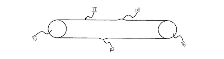
図3は転写ベルトに巻きぐせが形成された状態を示す図である。 FIG. 3 is a diagram illustrating a state in which winding is formed on the transfer belt.
図において、17は転写ベルト、75はドライブローラ、76はアイドルローラ、p1、p2は転写ベルト17に巻きぐせが形成された部分を表す巻きぐせ部である。該巻きぐせ部p1、p2は、ドライブローラ75及びアイドルローラ76によって転写ベルト17に一定のテンションが加えられた状態で長時間放置された場合等に、転写ベルト17においてドライブローラ75及びアイドルローラ76と当接する部分が伸長されることによって形成される。そして、前記巻きぐせ部p1、p2が形成された後、転写ベルト17を走行させると、巻きぐせ部p1、p2は、変形しているので、他の部分より盛り上がった状態で移動させられる。
In the figure, 17 is a transfer belt, 75 is a drive roller, 76 is an idle roller, and p1 and p2 are winding portions that represent portions where the
特に、プリンタが高温下に置かれたとき、前記転写ベルト17の材質の許容応力(弾性限度)を超えて外力が加わったとき等は、転写ベルト17に伸びも発生してしまう。このような転写ベルト17を使用して印刷を行った場合、巻きぐせ、伸び等によって印刷品位が低下してしまう。
In particular, when the printer is placed at a high temperature and when an external force is applied exceeding the allowable stress (elastic limit) of the material of the
また、モノクロ印刷が行われる際の画像形成ユニット16Y、16M、16Cと転写ユニット66との離間量が十分でない場合で、かつ、巻きぐせ等が形成された転写ベルト17を使用した場合、用紙が巻きぐせ部p1、p2に送られてくると、用紙の印刷面と画像形成ユニット16Y、16M、16Cの下面とが擦れてしまい、印刷品位が低下してしまう。
In addition, when the distance between the
そこで、本実施の形態においては、転写ベルト17が一定のテンションが加えられた状態で長時間放置されても、転写ベルト17に巻きぐせ部p1、p2が形成されるのを防止するようにしている。
Therefore, in this embodiment, even if the
次に、前記構成の転写ユニット66について説明する。
Next, the
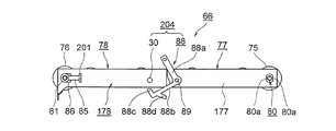
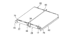
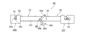
図1は本発明の第1の実施の形態における転写ユニットの要部を示す正面図、図4は本発明の第1の実施の形態における転写ユニットの要部を示す平面図、図5は本発明の第1の実施の形態における転写ユニットの斜視図、図6は本発明の第1の実施の形態における転写ユニットの要部を示す斜視図、図7は本発明の第1の実施の形態における第1、第2のベルトユニット部の第1の状態を示す断面図、図8は本発明の第1の実施の形態における第1、第2のベルトユニット部の第2の状態を示す断面図である。 1 is a front view showing a main part of a transfer unit according to the first embodiment of the present invention, FIG. 4 is a plan view showing a main part of the transfer unit according to the first embodiment of the present invention, and FIG. FIG. 6 is a perspective view showing a main part of the transfer unit according to the first embodiment of the present invention, and FIG. 7 is a perspective view showing the main part of the transfer unit according to the first embodiment of the present invention. Sectional drawing which shows the 1st state of the 1st, 2nd belt unit part in FIG. 8, FIG. 8 is a cross section which shows the 2nd state of the 1st, 2nd belt unit part in the 1st Embodiment of this invention. FIG.
図において、66は転写ユニットであり、該転写ユニット66は、第1の支持部材としての第1のベルトユニット部77、及び第2の支持部材としての第2のベルトユニット部78を連結することによって形成される。そして、前記第1のベルトユニット部77にドライブローラ75が、第2のベルトユニット部78にアイドルローラ76がそれぞれ配設され、転写ベルト17が、ドライブローラ75及びアイドルローラ76に巻き付けられた状態で、ドライブローラ75とアイドルローラ76とによって張設される。
In the figure,
前記第1のベルトユニット部77において、ドライブローラ75は、支持部材としてのベアリング80によって側板177に対して回転自在に支持され、前記ドライブローラ75の軸の一端に駆動ギヤ79が取り付けられ、該駆動ギヤ79は、前記ベルトモータと連結される。なお、前記ベアリング80は、Iカットされた形状を有し、平行な二つの面80aを備え、前記側板177に固定される。
In the
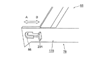
一方、第2のベルトユニット部78において、側板178に長穴86が図6の矢印A、B方向に向けて形成され、前記アイドルローラ76は、支持部材としてのベアリング81によって、側板178及び長穴86に対して、矢印A、B方向に摺動可能に支持される。なお、前記ベアリング81は円形の形状を有する。
On the other hand, in the
そして、前記アイドルローラ76は、ベアリング81と、側板178から突出させて形成された支持部201との間に配設された付勢部材としての加圧スプリング85によって矢印A方向に付勢され、転写ベルト17にテンションを加える。また、前記加圧スプリング85は、アイドルローラ76を転写ベルト17の走行方向に対して直角の方向に押圧する。
The
さらに、第2のベルトユニット部78においては、画像を形成するのに伴って、転写ベルト17上に残ったトナーを掻き取るためのクリーニング装置としてのクリーニングブレード82が配設され、該クリーニングブレード82は、転写ベルト17を介してアイドルローラ76と対向させて、かつ、転写ベルト17と当接させて配設される。
Further, in the
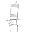
そして、第2のベルトユニット部78は、第1のベルトユニット部77に対して、連結軸84を揺動支点として揺動自在に連結され、前記第1、第2のベルトユニット部77、78が、図7に示されるような一直線状に延在させられた伸展状態を採るのに伴って、前記転写ユニット66は、転写ベルト17にテンションが加えられた第1の状態に置かれ、第1、第2のベルトユニット部77、78が、図8に示されるような「く」字状に曲折させられた屈曲状態を採るのに伴って、転写ユニット66は、転写ベルト17を弛ませた第2の状態に置かれる。なお、前記第1、第2のベルトユニット部77、78についても、伸展状態を第1の状態といい、屈曲状態を第2の状態という。
The
そのために、第1のベルトユニット部77は、第2のベルトユニット部78と対向する面S1が平坦であるのに対して、第2のベルトユニット部78は、第1のベルトユニット部77と対向する面S2にテーパ87が形成され、該テーパ87は、第1のベルトユニット部77に対して第2のベルトユニット部78を矢印C方向に回動させたときに、回動を規制し、所定量以上回動させないための規制部材として、かつ、ストッパとして作用する。前記所定量は、装置本体内の転写ユニット66と、該転写ユニット66の取付部との関係から算出され、本実施の形態においては、20〔°〕にされる。
Therefore, the first
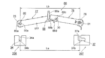
また、前記転写ユニット66を第2の状態に保持するために、転写ユニット66の両縁(左右)において第1、第2のベルトユニット部77、78間にロック装置204が配設される。該ロック装置204は、第1、第2のベルトユニット部77、78のうちの一方、本実施の形態においては、第1のベルトユニット部77に対して支点89を揺動中心として揺動自在に配設された係止部材としてのロック部材88、及び第1、第2のベルトユニット部77、78のうちの他方、本実施の形態においては、第2のベルトユニット部78に配設された被係止部材としての突起30を備える。前記ロック部材88は、回動に伴って、転写ユニット66を第1、第2の状態間で切り換える切換部材を構成する。
Further, in order to hold the
前記ロック部材88は、支点89から延びる第1のアーム88a、支点89から第1のアーム88aに対して所定の角度、本実施の形態においては、直角に延びる第2のアーム88b、該第2のアーム88bの先端から第1のアーム88aと平行に延びる第1の係止部としてのフック部88c、及び前記第2のアーム88bの先端よりわずかに支点89側において、フック部88cと逆方向に斜めに延びる第2の係止部としてのフック部88dを備え、転写ユニット66が第2の状態に置かれたときに、フック部88cと突起30とが係止させられる。また、転写ユニット66の左右に配設された各ロック部材88は、第1のアーム88aの先端で棒状の取手83によって連結される。該取手83はロック部材88と一体に揺動自在に配設される。
The
そして、操作者が前記取手83を把持し、転写ユニット66を持ち上げると、前記フック部88dと突起30とが係止させられる。したがって、ロック装置204は、第1のベルトユニット部77と第2のベルトユニット部78とが所定の角度以上回動しないようにするためのストッパ部材として作用する。
When the operator grips the
次に、前記転写ユニット66を装置本体に装着する方法について説明する。
Next, a method for mounting the
図9は本発明の第1の実施の形態における転写ユニットをプリンタに装着する状態を示す第1の図、図10は本発明の第1の実施の形態における転写ユニットをプリンタに装着する状態を示す第2の図、図11は本発明の第1の実施の形態における転写ユニットをプリンタに装着するための取付け溝の状態を示す第1の図、図12は本発明の第1の実施の形態における転写ユニットをプリンタに装着する状態を示す第3の図、図13は本発明の第1の実施の形態における転写ユニットをプリンタに装着するための取付け溝の状態を示す第2の図、図14は本発明の第1の実施の形態における転写ユニットをプリンタに装着する状態を示す第4の図である。 FIG. 9 is a first diagram illustrating a state where the transfer unit according to the first embodiment of the present invention is mounted on the printer, and FIG. 10 illustrates a state where the transfer unit according to the first embodiment of the present invention is mounted on the printer. FIG. 11 is a first view showing the state of a mounting groove for mounting the transfer unit in the printer according to the first embodiment of the present invention, and FIG. 12 is a first embodiment of the present invention. FIG. 13 is a third diagram showing a state in which the transfer unit in the embodiment is mounted on the printer, FIG. 13 is a second diagram showing a state of the mounting groove for mounting the transfer unit in the printer according to the first embodiment of the present invention, FIG. 14 is a fourth diagram showing a state in which the transfer unit according to the first embodiment of the present invention is mounted on the printer.
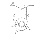
図において、206、207は装置本体の所定の箇所に取り付けられ、転写ユニット66を装置本体に対して着脱するための取付部であり、取付部206は、ベアリング80を収容して支持するための第1の溝としての挿入溝34を備える。該挿入溝34は、垂直方向に形成され、前記ベアリング80を導入するための導入部34a、及びベアリング80を保持するための保持部34bを備える。
In the figure,
前述されたように、ベアリング80はIカットすることによって形成された部分、すなわち、Iカット部の二つの面80aを備え、導入部34aは、Iカット部を挟んでベアリング80を導入することができるように、各面80a間の距離よりわずかに大きくされ、保持部34bは、ベアリング80を揺動自在に収容することができるように、ベアリング80の径よりわずかに大きくされる。
As described above, the
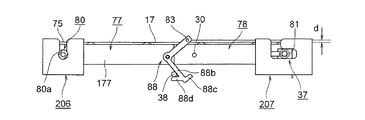
また、取付部207は、ベアリング81を収容して支持するための第2の溝としてのL字型の挿入溝37を備える。該挿入溝37は、垂直方向に形成され、ベアリング81を導入するための導入部37a、及び該導入部37aの底から水平方向に形成され、ベアリング81を保持するための保持部37bを備える。前記導入部37a及び保持部37bは、ベアリング81を導入し、保持することができるように、該ベアリング81の径よりわずかに大きくされる。
Further, the mounting
前記挿入溝34、37間の距離、すなわち、導入部34aの中心と導入部37aの中心との距離をLaとし、第1、第2のベルトユニット部77、78を第2の状態に置いたときのベアリング80、81の各中心間の距離をLbとしたとき、距離La、Lbは等しくされる。
The distance between the
なお、前記転写ユニット66を装置本体に装着する場合、取手83を把持し、ベアリング80、81を、図10に示されるように、挿入溝34、37内にそれぞれ挿入する。このとき、転写ユニット66は第2の状態に置かれ、ベアリング80は、面80aが垂直方向に向くように側板177に取り付けられる。したがって、図10及び11に示されるように、ベアリング80は、導入部34aを通り保持部34bに到達し、該保持部34b内に収容される。また、ベアリング81は導入部37aを通り、底部に到達する。
When the
続いて、ロック部材88を矢印C方向に回動させながら転写ユニット66を下方に押し下げると、図12に示されるように、フック部88cと突起30との係止が解除され、第1、第2のベルトユニット部77、78が一直線状になり、転写ユニット66は第1の状態に置かれる。このとき、第1のベルトユニット部77が水平になるのに伴って、図13に示されるように、ベアリング80が保持部34b内で矢印E方向に回動させられ、面80aが傾く。その結果、ベアリング80は挿入溝34から外れなくなる。また、図10に示されるように、ベアリング81が、挿入溝37を矢印D方向に移動し、保持部37b内に収容される。その結果、ベアリング81は挿入溝37から外れなくなる。このようにして、転写ユニット66を装置本体に装着することができる。
Subsequently, when the
なお、前記転写ユニット66が第1の状態に置かれた後、ロック部材88を更に矢印C方向に回動させると、図14に示されるように、フック部88dが装置本体の所定の箇所に配設された被係止部としての突起38と係止させられる。これに伴って、ロック部材88がロック状態に置かれ、転写ユニット66は第1の状態に保持される。したがって、前記転写ユニット66が装置本体に装着された後、印刷動作時の振動等によって転写ユニット66が第2の状態になるのを防止することができる。
When the
なお、前記ロック部材88がロック状態に置かれると、取手83と転写ベルト17の表面との間に隙間dが形成される。該隙間dは、用紙の通過を妨げない量で形成されるが、用紙の厚さ、誤差等を考慮して、2〔mm〕以上にするのが好ましい。また、前記取手83は、画像形成ユニット16Bk(図2)、16Y、16M、16Cと接触しない位置に配設される。
When the
本実施の形態においては、例えば、転写ユニット66の製造時における次工程待ち、出荷待ち等において、転写ユニット66は第2の状態に置かれ、転写ベルト17にテンションが加わらないようにされる。そのために、取手83を把持したときに、第1、第2のベルトユニット部77、78が曲折して延在させられ、フック部88cと突起30とが係止させられる。
In the present embodiment, the
したがって、前記転写ユニット66を第2の状態に置くことによって、例えば、転写ユニット66の製造時における次工程待ち、出荷待ち等において長時間放置された場合、転写ユニット66が高温下に置かれた場合等においても、転写ベルト17に伸びが発生するのを防止することができ、転写ベルト17に巻きぐせが形成されるのを防止することができる。なお、転写ベルト17の材質の許容応力を超える外力が加わらないので、転写ベルト17に伸びが発生するのを防止することができ、巻きぐせが形成されるのを防止することができる。その結果、印刷品位が低下するのを防止することができる。
Therefore, by placing the
また、巻きぐせが形成されるのが防止されるので、モノクロ印刷を行うときに、カラーの画像形成ユニット16Y、16M、16Cを退避させ、ブラックの画像形成ユニット16Bkだけで画像を形成するカラーのプリンタにおけるモノクロ印刷の印刷品位が低下するのを防止することができる。
Further, since curling is prevented, the color
なお、例えば、転写ユニット66の製造時における次工程待ち、出荷待ち等において長時間放置される場合、転写ユニット66が第2の状態に置かれ、ベアリング80、81の各中心間の距離Lbが第1の状態より短くされると、転写ベルト17にたるみが生じる。このとき、転写ベルト17は、アイドルローラ76及びクリーニングブレード82によって挟まれている。また、転写ベルト17には、転写ベルト17を斜行させないために、該転写ベルト17の縁部に図示されないビードが配設されていて、該ビードは、アイドルローラ76の図示されないプーリによって案内される。したがって、転写ベルト17は、アイドルローラ76及びクリーニングブレード82によって挟まれ、かつ、転写ベルト17のビードが前記プーリによって押さえられることになるので、転写ユニット66から外れることはない。
For example, when the
なお、第1、第2のベルトユニット部77、78を第1の状態に置くと、転写ベルト17にテンションが加わるので、ドライブローラ75を回転させることによって、転写ベルト17を走行させることができる。
When the first and second
次に、本発明の第2の実施の形態について説明する。なお、第1の実施の形態と同じ構造を有するものについては、同じ符号を付与し、同じ構造を有することによる発明の効果については同実施の形態の効果を援用する。 Next, a second embodiment of the present invention will be described. In addition, about the thing which has the same structure as 1st Embodiment, the same code | symbol is provided and the effect of the same embodiment is used about the effect of the invention by having the same structure.
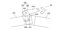
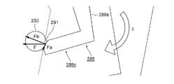
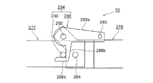
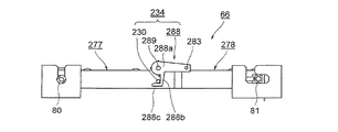
図15は本発明の第2の実施の形態における転写ユニットの要部を示す断面図、図16は本発明の第2の実施の形態における転写ユニットを第1の状態に置くときのロック装置の動作を示す第1の図、図17は本発明の第2の実施の形態における転写ユニットを第1の状態に置くときのロック装置の動作を示す第2の図、図18は本発明の第2の実施の形態における転写ユニットが第1の状態に置かれたときのロック装置を示す図、図19は本発明の第2の実施の形態における転写ユニットをプリンタに装着する状態を示す図である。 FIG. 15 is a cross-sectional view showing the main part of the transfer unit according to the second embodiment of the present invention, and FIG. 16 shows the lock device when the transfer unit according to the second embodiment of the present invention is placed in the first state. FIG. 17 is a second diagram illustrating the operation of the locking device when the transfer unit according to the second embodiment of the present invention is placed in the first state, and FIG. 18 is a diagram illustrating the operation of the present invention. FIG. 19 is a diagram illustrating a lock device when the transfer unit according to the second embodiment is placed in the first state, and FIG. 19 is a diagram illustrating a state where the transfer unit according to the second embodiment of the present invention is mounted on the printer. is there.
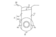
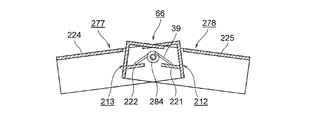
本実施の形態においては、第1の支持部材としての第1のベルトユニット部277と第2の支持部材としての第2のベルトユニット部278とは、連結軸284を揺動支点として揺動自在に連結され、前記連結軸284に付勢部材としてのトーションスプリング39が配設され、該トーションスプリング39は、ベルトユニットとしての転写ユニット66を第2の状態になるように付勢する。そのために、前記第1のベルトユニット部277の前壁212の内側に、支持部としての突起221が、前記第2のベルトユニット部278の前壁213の内側に、支持部としての突起222がそれぞれ形成され、前記トーションスプリング39の一端が突起221に、他端が突起222にそれぞれ当接させられる。
In the present embodiment, the first
また、第1のベルトユニット部277に対して第2のベルトユニット部278を回動させたときに、前記第1のベルトユニット部277の上面壁224と前壁213とが当接し、前記第2のベルトユニット部278の上面壁225と前壁212とが当接する。したがって、前壁212、213は、第2のベルトユニット部278を所定量以上回動させないためのストッパとして作用する。
When the
また、転写ユニット66を第2の状態から第1の状態に置くために、第1、第2のベルトユニット部277、278間にロック装置234が配設される。該ロック装置234は、転写ユニット66の両縁(左右)において配設され、第1、第2のベルトユニット部277、278のうちの一方、本実施の形態においては、第2のベルトユニット部278に対して支点289を揺動中心として揺動自在に配設された係止部材としてのロック部材288、及び第1、第2のベルトユニット部277、278のうちの他方、本実施の形態においては、第1のベルトユニット部277に形成された被係止部材としての突起230を備える。
Further, in order to place the
前記ロック部材288は、支点289から延びる第1のアーム288a、支点289から第1のアーム288aに対して所定の角度で、本実施の形態においては、直角に延びる第2のアーム288b、及び該第2のアーム288bの先端から第1のアーム288aと平行に、かつ、反対方向に延びる係止部としてのフック部288cを備え、転写ユニット66が第1の状態に置かれたときに、フック部288cと突起230とが係止させられる。また、各ロック部材288は、第1のアーム288aの先端で棒状の取手283によって連結される。
The
本実施の形態においては、例えば、転写ユニット66の製造時における次工程待ち、出荷待ち等において長時間放置される場合、転写ユニット66は第2の状態に置かれ、前記トーションスプリング39の付勢力によって第1、第2のベルトユニット部277、278が、図16に示されるような「く」字状に曲折させられる。それによって、転写ベルト17にテンションが加わらないようにされる。
In the present embodiment, for example, when the
したがって、前記転写ユニット66を第2の状態に置くことによって、例えば、転写ユニット66の製造時における次工程待ち、出荷待ち等において長時間放置された場合、転写ユニット66が高温下に置かれた場合等においても、転写ベルト17に伸びが発生するのを防止することができ、転写ベルト17に巻きぐせが形成されるのを防止することができる。なお、転写ベルト17の材質の許容応力(弾性限度)を超える外力が加わらないので、転写ベルト17に伸びが発生するのを防止することができ、巻きぐせが形成されるのを防止することができる。その結果、印刷品位が低下するのを防止することができる。
Therefore, by placing the
また、巻きぐせが形成されるのが防止されるので、モノクロ印刷を行うときに、カラーの画像形成ユニット16Y、16M、16Cを退避させてブラックの画像形成ユニット16Bkだけで画像を形成するカラーのプリンタにおけるモノクロ印刷の印刷品位が低下するのを防止することができる。
Further, since the formation of curling is prevented, when performing monochrome printing, the color
また、転写ユニット66を装置本体から外した状態で、例えば、テーブル等の上に置いた場合においても、トーションスプリング39の付勢力によって、転写ユニット66は第2の状態を保持することができる。
Further, even when the
次に、転写ユニット66を装置本体に装着する方法について説明する。
Next, a method for attaching the
この場合、まず、取手283を把持し、第1の実施の形態と同様に、ベアリング80、81を挿入溝34、37内にそれぞれ挿入する。このとき、転写ユニット66は第2の状態に置かれる。
In this case, first, the
続いて、ロック部材88を矢印E方向に回動させると、前記フック部288cの先端に形成された当接部としてのテーパ291が突起230に接触する。そして、前記テーパ291は、矢印方向に力Fで突起230を押圧する。このとき、テーパ291は、分力Fbで突起230を押すが、分力Faによって第2のアーム288b及びフック部288cが変形させられ、テーパ291が突起230の表面を滑り、その結果、図18に示されるように、フック部288cと突起230とが係止させられる。それに伴って、転写ユニット66は、第1の状態になり、装置本体に装着される。
Subsequently, when the
このように、本実施の形態においては、トーションスプリング39の付勢力によって転写ユニット66が第2の状態に保持されるので、転写ベルト17が弛んだ状態を保持することができる。したがって、転写ユニット66が装置本体から外されている場合に、転写ベルト17に巻きぐせが形成されるのを確実に防止することができる。
Thus, in the present embodiment, the
前記各実施の形態においては、プリンタに配設された転写ユニット66について説明したが、本発明を、ベルトユニットを使用する複合機、ファクシミリ装置、複合機等に適用することができる。
In each of the above embodiments, the
なお、本発明は前記各実施の形態に限定されるものではなく、本発明の趣旨に基づいて種々変形させることが可能であり、それらを本発明の範囲から排除するものではない。 The present invention is not limited to the above embodiments, and various modifications can be made based on the gist of the present invention, and they are not excluded from the scope of the present invention.
17 転写ベルト
66 転写ユニット
75 ドライブローラ
76 アイドルローラ
77、277 第1のベルトユニット部
78、278 第2のベルトユニット部
85 加圧スプリング
17
Claims (9)
(b)該第1、第2のローラ間に配設されたベルトと、
(c)前記第1のローラを支持する第1の支持部材と、
(d)前記第2のローラを支持する第2の支持部材と、
(e)前記第1、第2の支持部材間に配設され、第1、第2の支持部材間に付勢力を発生させる付勢部材と、
(f)前記第1の支持部材に対して揺動自在に配設されたロック部材とを有するとともに、
(g)ベルトユニットは、前記付勢部材による付勢及びロック部材の係止に伴って、前記ベルトに所定の張力が加えられる第1の状態、及び前記所定の張力が加えられない第2の状態に保持されることを特徴とするベルトユニット。 (A) first and second rollers;
(B) a belt disposed between the first and second rollers;
(C) a first support member that supports the first roller;
(D) a second support member that supports the second roller;
(E) an urging member disposed between the first and second support members and generating an urging force between the first and second support members ;
(F) having a lock member that is swingably disposed with respect to the first support member;
(G) The belt unit includes a first state in which a predetermined tension is applied to the belt in accordance with the urging by the urging member and the locking of the lock member , and a second state in which the predetermined tension is not applied. A belt unit characterized by being held in a state.
(b)前記第1の係止部を被係止部材に係止させることによって、ベルトユニットが前記第2の状態に保持される請求項5に記載のベルトユニット。 (A) the second support member includes a locked member;
(B) The belt unit according to claim 5, wherein the belt unit is held in the second state by locking the first locking portion to the locked member.
Priority Applications (1)
| Application Number | Priority Date | Filing Date | Title |
|---|---|---|---|
| JP2010195311A JP4792121B2 (en) | 2010-09-01 | 2010-09-01 | Belt unit and image forming apparatus |
Applications Claiming Priority (1)
| Application Number | Priority Date | Filing Date | Title |
|---|---|---|---|
| JP2010195311A JP4792121B2 (en) | 2010-09-01 | 2010-09-01 | Belt unit and image forming apparatus |
Related Parent Applications (1)
| Application Number | Title | Priority Date | Filing Date |
|---|---|---|---|
| JP2010091426A Division JP4639264B2 (en) | 2010-04-12 | 2010-04-12 | Belt unit and image forming apparatus |
Publications (2)
| Publication Number | Publication Date |
|---|---|
| JP2010266901A JP2010266901A (en) | 2010-11-25 |
| JP4792121B2 true JP4792121B2 (en) | 2011-10-12 |
Family
ID=43363855
Family Applications (1)
| Application Number | Title | Priority Date | Filing Date |
|---|---|---|---|
| JP2010195311A Active JP4792121B2 (en) | 2010-09-01 | 2010-09-01 | Belt unit and image forming apparatus |
Country Status (1)
| Country | Link |
|---|---|
| JP (1) | JP4792121B2 (en) |
Family Cites Families (5)
| Publication number | Priority date | Publication date | Assignee | Title |
|---|---|---|---|---|
| JPH0652462B2 (en) * | 1984-07-10 | 1994-07-06 | 富士ゼロックス株式会社 | End-belt-like photoconductor canceling device in copier |
| JPH0538369Y2 (en) * | 1985-10-14 | 1993-09-28 | ||
| US4657370A (en) * | 1985-12-24 | 1987-04-14 | Xerox Corporation | Belt support and tracking apparatus |
| JP3704085B2 (en) * | 2001-12-25 | 2005-10-05 | 京セラ株式会社 | Belt unit for electrophotographic equipment |
| JP2007057953A (en) * | 2005-08-25 | 2007-03-08 | Brother Ind Ltd | Image forming apparatus |
-
2010
- 2010-09-01 JP JP2010195311A patent/JP4792121B2/en active Active
Also Published As
| Publication number | Publication date |
|---|---|
| JP2010266901A (en) | 2010-11-25 |
Similar Documents
| Publication | Publication Date | Title |
|---|---|---|
| JP4496243B2 (en) | Belt unit and image forming apparatus | |
| US7925199B2 (en) | Image forming apparatus | |
| US9256199B2 (en) | Image forming apparatus having spacing configuration for process cartridge | |
| JP2010128338A (en) | Process cartridge and image forming apparatus | |
| JP4792121B2 (en) | Belt unit and image forming apparatus | |
| JP4639264B2 (en) | Belt unit and image forming apparatus | |
| JP2007041402A (en) | Belt unit, image forming apparatus and belt unit assembling method | |
| US20150234327A1 (en) | Cleaning device and image forming apparatus | |
| KR100609907B1 (en) | Image Forming Device | |
| JP6269555B2 (en) | Transfer device and image forming apparatus having the same | |
| JP4842683B2 (en) | Image forming apparatus | |
| US11385563B2 (en) | Developing cartridge having first inclined surface movable together with first shaft, and second inclined surface movable together with second shaft | |
| JP7363568B2 (en) | Media transport device and image forming device | |
| JP7415805B2 (en) | Media transport device and image forming device | |
| CN107703725B (en) | Transfer unit and image forming apparatus | |
| JP7314786B2 (en) | image forming device | |
| JP2002372819A (en) | Image forming device | |
| US12092989B2 (en) | Unit accommodation apparatus and image forming apparatus | |
| JP7552418B2 (en) | Roller unit and image forming apparatus | |
| JP5192974B2 (en) | Medium storage device and image forming apparatus | |
| JP6280605B2 (en) | Paper feeding device and image forming apparatus | |
| JP2018055006A (en) | Fixing apparatus and image forming apparatus | |
| JP6451834B2 (en) | Image forming apparatus | |
| JP2015131725A (en) | Paper feeding device and image forming apparatus | |
| JP2010265977A (en) | Coupling and image forming apparatus equipped with the same |
Legal Events
| Date | Code | Title | Description |
|---|---|---|---|
| A621 | Written request for application examination |
Free format text: JAPANESE INTERMEDIATE CODE: A621 Effective date: 20100901 |
|
| A131 | Notification of reasons for refusal |
Free format text: JAPANESE INTERMEDIATE CODE: A131 Effective date: 20101130 |
|
| A521 | Request for written amendment filed |
Free format text: JAPANESE INTERMEDIATE CODE: A523 Effective date: 20110126 |
|
| A131 | Notification of reasons for refusal |
Free format text: JAPANESE INTERMEDIATE CODE: A131 Effective date: 20110329 |
|
| A521 | Request for written amendment filed |
Free format text: JAPANESE INTERMEDIATE CODE: A523 Effective date: 20110526 |
|
| TRDD | Decision of grant or rejection written | ||
| A01 | Written decision to grant a patent or to grant a registration (utility model) |
Free format text: JAPANESE INTERMEDIATE CODE: A01 Effective date: 20110712 |
|
| A01 | Written decision to grant a patent or to grant a registration (utility model) |
Free format text: JAPANESE INTERMEDIATE CODE: A01 |
|
| A61 | First payment of annual fees (during grant procedure) |
Free format text: JAPANESE INTERMEDIATE CODE: A61 Effective date: 20110722 |
|
| FPAY | Renewal fee payment (event date is renewal date of database) |
Free format text: PAYMENT UNTIL: 20140729 Year of fee payment: 3 |
|
| R150 | Certificate of patent or registration of utility model |
Free format text: JAPANESE INTERMEDIATE CODE: R150 Ref document number: 4792121 Country of ref document: JP Free format text: JAPANESE INTERMEDIATE CODE: R150 |
|
| S111 | Request for change of ownership or part of ownership |
Free format text: JAPANESE INTERMEDIATE CODE: R313111 |
|
| R350 | Written notification of registration of transfer |
Free format text: JAPANESE INTERMEDIATE CODE: R350 |