JP4792040B2 - Magnetically actuated locking device and related security device - Google Patents
Magnetically actuated locking device and related security device Download PDFInfo
- Publication number
- JP4792040B2 JP4792040B2 JP2007545676A JP2007545676A JP4792040B2 JP 4792040 B2 JP4792040 B2 JP 4792040B2 JP 2007545676 A JP2007545676 A JP 2007545676A JP 2007545676 A JP2007545676 A JP 2007545676A JP 4792040 B2 JP4792040 B2 JP 4792040B2
- Authority
- JP
- Japan
- Prior art keywords
- security device
- latch
- security
- bottom housing
- magnetic drive
- Prior art date
- Legal status (The legal status is an assumption and is not a legal conclusion. Google has not performed a legal analysis and makes no representation as to the accuracy of the status listed.)
- Expired - Fee Related
Links
Images


Classifications
-
- E—FIXED CONSTRUCTIONS
- E05—LOCKS; KEYS; WINDOW OR DOOR FITTINGS; SAFES
- E05B—LOCKS; ACCESSORIES THEREFOR; HANDCUFFS
- E05B73/00—Devices for locking portable objects against unauthorised removal; Miscellaneous locking devices
-
- E—FIXED CONSTRUCTIONS
- E05—LOCKS; KEYS; WINDOW OR DOOR FITTINGS; SAFES
- E05B—LOCKS; ACCESSORIES THEREFOR; HANDCUFFS
- E05B73/00—Devices for locking portable objects against unauthorised removal; Miscellaneous locking devices
- E05B73/0017—Anti-theft devices, e.g. tags or monitors, fixed to articles, e.g. clothes, and to be removed at the check-out of shops
- E05B73/0047—Unlocking tools; Decouplers
- E05B73/0052—Unlocking tools; Decouplers of the magnetic type
-
- Y—GENERAL TAGGING OF NEW TECHNOLOGICAL DEVELOPMENTS; GENERAL TAGGING OF CROSS-SECTIONAL TECHNOLOGIES SPANNING OVER SEVERAL SECTIONS OF THE IPC; TECHNICAL SUBJECTS COVERED BY FORMER USPC CROSS-REFERENCE ART COLLECTIONS [XRACs] AND DIGESTS
- Y10—TECHNICAL SUBJECTS COVERED BY FORMER USPC
- Y10T—TECHNICAL SUBJECTS COVERED BY FORMER US CLASSIFICATION
- Y10T24/00—Buckles, buttons, clasps, etc.
- Y10T24/50—Readily interlocking, two-part fastener requiring either destructive or tool disengagement
-
- Y—GENERAL TAGGING OF NEW TECHNOLOGICAL DEVELOPMENTS; GENERAL TAGGING OF CROSS-SECTIONAL TECHNOLOGIES SPANNING OVER SEVERAL SECTIONS OF THE IPC; TECHNICAL SUBJECTS COVERED BY FORMER USPC CROSS-REFERENCE ART COLLECTIONS [XRACs] AND DIGESTS
- Y10—TECHNICAL SUBJECTS COVERED BY FORMER USPC
- Y10T—TECHNICAL SUBJECTS COVERED BY FORMER US CLASSIFICATION
- Y10T292/00—Closure fasteners
- Y10T292/11—Magnetic
-
- Y—GENERAL TAGGING OF NEW TECHNOLOGICAL DEVELOPMENTS; GENERAL TAGGING OF CROSS-SECTIONAL TECHNOLOGIES SPANNING OVER SEVERAL SECTIONS OF THE IPC; TECHNICAL SUBJECTS COVERED BY FORMER USPC CROSS-REFERENCE ART COLLECTIONS [XRACs] AND DIGESTS
- Y10—TECHNICAL SUBJECTS COVERED BY FORMER USPC
- Y10T—TECHNICAL SUBJECTS COVERED BY FORMER US CLASSIFICATION
- Y10T70/00—Locks
- Y10T70/50—Special application
- Y10T70/5004—For antitheft signaling device on protected article
-
- Y—GENERAL TAGGING OF NEW TECHNOLOGICAL DEVELOPMENTS; GENERAL TAGGING OF CROSS-SECTIONAL TECHNOLOGIES SPANNING OVER SEVERAL SECTIONS OF THE IPC; TECHNICAL SUBJECTS COVERED BY FORMER USPC CROSS-REFERENCE ART COLLECTIONS [XRACs] AND DIGESTS
- Y10—TECHNICAL SUBJECTS COVERED BY FORMER USPC
- Y10T—TECHNICAL SUBJECTS COVERED BY FORMER US CLASSIFICATION
- Y10T70/00—Locks
- Y10T70/50—Special application
- Y10T70/5009—For portable articles
- Y10T70/5031—Receptacle
-
- Y—GENERAL TAGGING OF NEW TECHNOLOGICAL DEVELOPMENTS; GENERAL TAGGING OF CROSS-SECTIONAL TECHNOLOGIES SPANNING OVER SEVERAL SECTIONS OF THE IPC; TECHNICAL SUBJECTS COVERED BY FORMER USPC CROSS-REFERENCE ART COLLECTIONS [XRACs] AND DIGESTS
- Y10—TECHNICAL SUBJECTS COVERED BY FORMER USPC
- Y10T—TECHNICAL SUBJECTS COVERED BY FORMER US CLASSIFICATION
- Y10T70/00—Locks
- Y10T70/70—Operating mechanism
- Y10T70/7051—Using a powered device [e.g., motor]
- Y10T70/7057—Permanent magnet
Abstract
Description
本願は、2004年12月7日出願の米国仮特許出願第60/633,813号、発明の名称「改良型EASセキュリティタグ」と、2005年5月23日出願の米国仮特許出願第60/683,657号、発明の名称「改良型EASセキュリティタグ」の優先権を請求する。これらの両出願の全内容は参照のためにここに取り入れられる。 This application is filed with US Provisional Patent Application No. 60 / 633,813, filed Dec. 7, 2004, entitled “Improved EAS Security Tag” and US Provisional Patent Application No. 60 / filed May 23, 2005. No. 683,657, claiming the priority of the title "Improved EAS Security Tag". The entire contents of both of these applications are hereby incorporated by reference.
関連出願
米国を指定するこの国際出願は米国を指定する以下の出願に関連する:
(1)「磁力作動の施錠装置と関連セキュリティ装置」;
(2)「拘束された細長い要素を有する物品のためのセキュリティ装置」;
(3)「ケーブルを有するセキュリティ装置の有するセキュリティ装置」;及び
(4)「ボトルのためのセキュリティ装置」
これらの関連出願は、本願とともに同時出願されたものであり、その全内容は参照のためにここに取り入れられる。
This International Application Designating the Related Application United States is related to the following applications designating the United States:
(1) "Magnetically actuated locking device and related security device";
(2) "Security device for articles with constrained elongated elements";
(3) “Security device with security device with cable”; and (4) “Security device for bottle”
These related applications are co-filed with the present application, the entire contents of which are hereby incorporated by reference.
セキュリティタグシステムは、管理区域から権限なく物品を取り去ることを防止するために設計される。例えば、典型的な電子物品監視(EAS)システムは監視システムと1つ以上のセキュリティタグを含むであろう。監視システムは管理区域のアクセスポイントに監視ゾーンを創成する。セキュリティタグは、
例えば、読み出し専用コンパクトディス(CD−ROM)、ミニCD−ROM、書き込み型コンパクトディス(CD−R)及び再書き込み型コンパクトディス(CD−RW)を含むいかなるタイプのコンパクトディスク(CD)と;例えば、DVD、読み出し専用DVD(DVD−ROM)、書き込み型DVD(DVD−R)、ハイデフィニッションDVD(HD−DVD)を含むいかなるタイプのデジタルビデオディスク又はデジタルバーサタイルディスク(DVD)と;ブルーレイディスク(BD)等の光ディスク(OD)のような監視される物品と;
例えば、眼鏡、ワイン他のボトル、宝石等のその他の監視される物品;
に固定されるセキュリティ装置内で囲まれる。監視されている物品が監視ゾーンに入ると、警報が発せられ、権限のない取り去りを示す。
Security tag systems are designed to prevent unauthorized removal of items from a controlled area. For example, a typical electronic article surveillance (EAS) system will include a surveillance system and one or more security tags. The monitoring system creates a monitoring zone at an access point in the management area. Security tag
For example, any type of compact disc (CD), including read-only compact disc (CD-ROM), mini-CD-ROM, writable compact disc (CD-R) and rewritable compact disc (CD-RW); Any type of digital video disc or digital versatile disc (DVD), including DVD, read-only DVD (DVD-ROM), writable DVD (DVD-R), high definition DVD (HD-DVD); Monitored items such as optical discs (OD) such as BD);
Other monitored items such as glasses, wine and other bottles, jewelry, etc .;
Enclosed in a security device. When the item being monitored enters the monitoring zone, an alert is issued indicating an unauthorized removal.
セキュリティ装置は多くの異なる物品に取り付けられる。セキュリティ装置は、物品からの権限ある取り外しを可能にするが、権限のない取り外しを比較的難しくすることが望ましい。そのため、一般に、セキュリティ装置の技術改善、特に、セキュリティ装置を物品に取り付けるシステムが必要とされる。 Security devices are attached to many different items. While the security device allows for authorized removal from the article, it is desirable to make unauthorized removal relatively difficult. Therefore, in general, there is a need for improved security device technology, particularly a system for attaching a security device to an article.
実施の形態の内容は、特に指摘されて、結論部で明瞭に請求される。しかしながら、構成と操作法の両方に関する実施の形態は、添付図面と共に以下の詳細な説明を読むことにより最も良く理解されるだろう。 The content of the embodiments is specifically pointed out and clearly claimed in the conclusion section. However, embodiments relating to both structure and operation will best be understood by reading the following detailed description in conjunction with the accompanying drawings.
実施の形態は、OD他の対象物等の物品にセキュリティタグを組み合わせる装置、システム及び方法に関する。例えば、1実施の形態は、施錠装置、セキュリティタグ及びハウジングを含んでなるセキュリティ装置を含むことができる。施錠装置は磁力作動のラッチと、この磁力作動のラッチをロック位置へ付勢するフレキシブル・エレメントと、ロック位置において磁力作動のラッチの少なくとも一部と噛み合うラッチはめ込み要素を含むことができる。ここに使用されるように、「ロック位置」は、磁力作動のラッチの一部又は全部が空隙の中に位置して前記ラッチはめ込み要素に係合され、接合され又は噛み合わされる位置のことをいう。ハウジング構造は、施錠装置と、セキュリティタグと、ラッチはめ込み要素と、物品をハウジングに部分的又は全体的に収納又は囲み、あるいは、ハウジングに固定するように構成される。ハウジングはCDその他のODを固定するように構成され、かつ、底部ハウジング、施錠装置カバー、セキュリティタグカバー、下カバー及び上カバーを含むことができる。施錠装置の磁力作動のラッチはロック位置においてラッチはめ込み要素に噛み合いハウジングをロックし、それにより、ハウジングに固定されているセキュリティタグを物品にロックする。ハウジングがロックされると、セキュリティ装置は、物品からハウジングを切り離すことを防止し又は抵抗する。別の実施の形態は、セキュリティ装置と、分離器(これは、磁石を含む装置とすることができる)を含むセキュリティシステムを含むことができる。分離器は、磁力作動のラッチを磁力によってロック位置から離すよう移動させることによってハウジングをアンロックするのに使われる。 Embodiments relate to an apparatus, a system, and a method for combining a security tag with an article such as an OD or other object. For example, one embodiment can include a security device comprising a locking device, a security tag, and a housing. The locking device may include a magnetically actuated latch, a flexible element that biases the magnetically actuated latch to a locked position, and a latch-fit element that engages at least a portion of the magnetically actuated latch in the locked position. As used herein, a “locked position” refers to a position where some or all of the magnetically actuated latch is located within the gap and is engaged, joined or mated to the latching engagement element. Say. The housing structure is configured to partially or fully enclose or secure the article in the housing, or to secure the locking device, the security tag, the latch-engaging element, and the housing. The housing is configured to secure a CD or other OD and can include a bottom housing, a locking device cover, a security tag cover, a lower cover, and an upper cover. The magnetically actuated latch of the locking device engages the latch-engaging element in the locked position and locks the housing, thereby locking the security tag secured to the housing to the article. When the housing is locked, the security device prevents or resists detachment of the housing from the article. Another embodiment can include a security system including a security device and a separator (which can be a device including a magnet). The separator is used to unlock the housing by moving the magnetically actuated latch away from the locked position by magnetic force.
明細書において「1実施の形態」又は「実施の形態」という場合、実施の形態に関して説明される特定の特徴、構造又は特性が少なくとも1実施の形態に含まれていることを意味することを喚起する必要があろう。明細書中の様々な箇所で「1実施の形態」といった場合、必ずしも、1つの同じ実施の形態のことではない。多数の特定の詳細が実施の形態の徹底的な理解を提供するためにここに詳しく説明される。しかしながら、実施の形態がこれらの特定の詳細なしで実施されうることは当業者によって理解される。他の例では、周知の方法、手順及び構成要素は、実施の形態をあいまいにしないように詳細には説明されていない。開示された特定の構造的機能的な詳細はここでの代表的例示であって、必ずしも実施の形態の範囲をそれに制限するとものではないのことが理解される。 In the specification, when “one embodiment” or “an embodiment” is referred to, it means that at least one embodiment includes a specific feature, structure, or characteristic described with respect to the embodiment. It will be necessary to do. References to “one embodiment” in various places in the specification are not necessarily all referring to the same embodiment. Numerous specific details are described in detail herein to provide a thorough understanding of the embodiments. However, it will be understood by one of ordinary skill in the art that the embodiments may be practiced without these specific details. In other instances, well-known methods, procedures, and components have not been described in detail so as not to obscure the embodiments. It is understood that the specific structural and functional details disclosed are representative examples herein and are not necessarily intended to limit the scope of the embodiments.
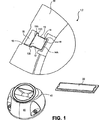
ここで、図に関して詳細に説明するが、全体を通して同様の部品にはで同様の参照番号を用いている。図1は、1実施の形態によるセキュリティシステム1とセキュリティ装置2に含むことができる複数の構成要素を示す正面図である。この実施の形態では、セキュリティシステム1はセキュリティ装置2と分離器40を含む。セキュリティ装置2は施錠装置10、セキュリティタグ20及びハウジング30を含むことができる。
Reference will now be made in detail to the figures, with like reference numerals being used for like parts throughout. FIG. 1 is a front view showing a plurality of components that can be included in a
施錠装置10を磁力作動の施錠装置とすることができ、それは磁力作動のラッチ12、フレキシブル・エレメント16及びラッチはめ込み要素18を含むことができる。
The
磁力作動のラッチ12は、ベース部端13A及び側面13B,13Cを含むベース部13と;ラッチ部端14Aを含むラッチ部14と;中心部15を含むことができる。
The magnetically actuated
磁力作動のラッチ12は、ベース部13の幅がラッチ部14と中心部15の幅と同じになるように、ほぼ正方形の形状であることができる。従って、ベース部13の幅、即ち、側面13Bと13Cの間の距離が対応するラッチ部14と中心部15の幅と同である。他の実施の形態では、ベース部13、ラッチ部14及び中心部15の幅を異なるようにすることができる。磁力作動のラッチ12は一定の細長断面を有することができる。
The magnetically actuated
しかしながら、磁力作動のラッチ12を望み通りに構成することができ、1個以上のピースを含み、任意の点、線又は面に関して対称又は非対称とすることができる。例えば、様々な実施の形態では、磁力作動のラッチ12を「T」型、「I」型、湾曲他の面とし、かつ、長方形、円形、厚い、空洞を持つ又は及び/又は非均一の断面形状を持つようにすることができ、あるいは、実施の形態の磁力作動のラッチ112に関してここで図示及び/又は説明されるようなものにすることができる。別の実施の形態では、磁力作動のラッチ12のラッチ部端14Aは1つ以上の歯、リブ、ノッチ、ジャギー、ポイント、カーブ、空隙他の形状(磁力作動のラッチ112の実施の形態に関してここに説明するもの)を含むことができ、また、ベース部端13Aを平坦又は他の形状とすることができる。さらに、ベース部端13Aを連続又は不連続にすることができる。ここに説明されるように、ラッチ部14などの磁力作動のラッチ12の少なくとも一部はラッチはめ込み要素18に係合又は噛み合い、あるいは、それを受け又はそれに挿入されるように構成される。
However, the magnetically actuated
1実施の形態では、セキュリティ装置2は複数の磁力作動のラッチ12を含み、各ラッチは、セキュリティ装置2の同じ又は異なる部分で、フレキシブル・エレメント16とラッチはめ込み要素18と共に配置される。例えば、1実施の形態では、複数の磁力作動のラッチ12はそれぞれ、例えば、物品を固定する部分、セキュリティタグ20を固定する部分などのセキュリティ装置2の別の部分と協働して該部分をロックする。
In one embodiment, the
磁力作動のラッチ12は、鉄、ニッケル若しくはコバルト、又は、鉄、ニッケル若しくはコバルトの合金を含むことができ、あるいは、それから形成することができる。1実施の形態では、磁力作動のラッチ12は、1個以上の磁性体を含むことができ、また、1個以上の非磁性体を含むことができる。実施の形態に関してここに示し及び/又は説明されるフレキシブル・エレメント116のように、フレキシブル・エレメント16を望み通りに、立方体、だ円体、コイル他の形に形成することができ、また、フレキシブル・エレメントは1つ以上のピースを含むことができ、あるいは、磁力作動のラッチ12に結合され、又はそれと一体的に形成される。1実施の形態では、フレキシブル・エレメント16は、例えば、板バネのような片持ち梁アームとして形成される。フレキシブル・エレメント16は、圧縮されたときに抵抗力を生じ、かつ、圧縮力が解放されたときに非圧縮形状を部分的又は完全に回復することができる軽くて、多孔性、半硬、弾性、ガスの及び/又はスポンジ状の材料を含むことができ、あるいは、そういった材料から形成される。例えば、様々な実施の形態では、フレキシブル・エレメント16は、フォームラバー、ポリマー・フォーム、セラミックフォーム他の発泡材;ゴム;他の材料から形成され又はそれらを含むことができる。フレキシブル・エレメント16はさらに、あるいは、代替的に、圧縮(圧迫)されたときに抵抗力を生じるように構成される。例えば、様々な実施の形態では、フレキシブル・エレメント16をメタル、端部、セラミック及び/又は別の材料を含むコイル、板他の片持ち梁式アーム又はバネ他の部材として構成することできる。フレキシブル・エレメント16の質量を様々にすることができる。
The magnetically actuated
望まれるように、1つ以上の穴他の空隙、リブ、歯、突起又は他の形などを備えるようにラッチはめ込み要素18を構成することができる。ラッチはめ込み要素18は1個以上のピースを含むことができ、また、ここで説明するように、ハウジング30から分離してあるいは、それと一体的に設けられる。ラッチはめ込み要素18は、磁力作動のラッチ12の少なくとも一部を受け又はそれに係合し、挿入され、若しくは噛み合うように構成される。例えば、磁力作動のラッチ12が長方形の面を有する細長い部材である1実施の形態では、ここで説明されるように、ラッチはめ込み要素18が空隙を有し、この空隙において、磁力作動のラッチ12のラッチ部14又は他の部分がロック位置に挿入されるように構成される。磁力作動のラッチ12がラッチ部端14Aにおいて歯を有する1実施の形態では、ラッチはめ込み要素18は、ロック位置において歯に噛み合うリブを備えるように構成される。セキュリティタグ20をセキュリティタグやラベルなどの検出可能なデバイスやシステムとすることができる。例えば、様々な実施の形態では、セキュリティタグ20をどんなタイプのEASタグ(例えば、無線周波(RF)タグ、音響磁気式タグ及び/又はそれらの組合せ)、無線周波識別(RFID)タグ、スマートタグ又は他の検出可能な盗難防止用若しくは他のタグとすることができる。セキュリティタグ20は、セキュリティタグ又はラベルのタイプに依存して、音響磁気式検出器、電磁検出器、無線周波検出器他の検出器等の対応する検出システム又は装置によって検出可能である。
As desired, the
図1の実施の形態において部分的に示されるハウジング30は、施錠装置10とセキュリティタグ20を部分的又は全体的に収納し及び/又は囲い、覆い、取り付け、インターロックし、あるいは固定するケーシング他の構造とされ、施錠装置10がロック位置にあるとき、ハウジングは物品にロックされる。ハウジング30と施錠装置はこのように協働して物品をハウジング30に固定又はロックし、従って、セキュリティ装置2をロックする。ハウジング30を所望のように構成することができ、また、ここで説明される実施の形態のハウジング130のように、施錠装置10、セキュリティタグ20及びセキュリティタグ20を取り付けるべき物品の形に基づいてハウジングを形作ることができる。ハウジング30はラッチはめ込み要素18を含むことができ、この要素18をハウジング30と一体的にすることとしてもよい。それに代えて、ハウジング30とラッチはめ込み要素18をペアにすることとしてもよい。ハウジング30はポリマー及び/又は他の材料を含むことができる。
The housing 30 partially shown in the embodiment of FIG. 1 is a casing or the like that houses and / or encloses, covers, attaches, interlocks, or secures the
セキュリティ装置2に含まれる構成要素は、以下のセキュリティ装置の実施の形態に関して説明されるようにセキュリティ装置2が物品にロックするように設けられる。セキュリティタグ2を再使用可能に又は1回限りの使用とすることができる。
The components included in the
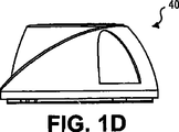
図1A−1Dは、それぞれ、1実施の形態による図1に示される分離器40の斜視図、平面部図、正面図及び側面図である。分離器40は磁石42を含み、それを収容する装置とされる。磁石42は、例えば、永久磁石や電磁石などのどんなタイプの磁石であってもよい。セキュリティシステム1に関して、分離器40をセキュリティ装置2と共に使用して、セキュリティ装置2を物品からアンロックすることができる。磁力作動のラッチ12を磁力によってロック位置から遠ざけてセキュリティ装置2のハウジング30をそれがロックされている物品から取り外すことを可能にするように、セキュリティ装置2の磁力作動のラッチ12に適度に近くに分離器40を位置させる。
1A-1D are a perspective view, a plan view, a front view, and a side view, respectively, of
様々な実施の形態では、分離器40は異なった磁石42を含むことができる。例えば、分離器40の磁石42は、磁力作動のラッチ12をロック位置から遠ざかるように移動させ、それにより、セキュリティ装置2をアンロックするのに必要である磁力に基づいて選択される。この磁力は、該移動に対抗する力を相殺するよりも大きなものを必要とするだろう。そのような対抗力は、例えば。フレキシブル・エレメント16が磁力作動のラッチ12によって圧縮されるときに該エレメントによって供給される抵抗力、移動の際にハウジング30及び/又は別の要素に接触する磁力作動のラッチ12によってもたらされる摩擦力、他の力を含むことができるであろう。分離器40が異なった構成を有し様々なセキュリティ装置に使用することを意図する別の実施の形態では、磁石42は、アンロックするのに最も強い磁石を必要とするセキュリティ装置をアンロックできるくらい強い磁力を持つものが選択されるであろう。
In various embodiments, the
1実施の形態では、セキュリティ装置2を1回の使用のための構成とすることができる。例えば、図1E及び1Fに示す1実施の形態では、セキュリティ装置2の磁力作動のラッチ12は、ロック位置でラッチはめ込み要素18に噛み合わせられるようにチャンネル3の中に置かれる。片持ち梁式アーム4,5などの1つ以上の板バネ他の片持ち梁式アームがバネ負荷構成でチャンネル3内に配置される。
In one embodiment, the
例えば、片持ち梁式アーム4は、図1Eで示される非負荷位置を有する。片持ち梁式アームは、その側部4Aがチャネル壁3Aに隣接するようにある位置まで曲げられ、それにより、バネ負荷される。次に、磁力作動のラッチ12を片持ち梁式アーム4の他側4Bに隣接させ、片持ち梁式アーム4の移動を防止しかつそのバネ負荷を保つように、チャンネル3内のロック位置に配置される。片持ち梁式アーム5を同様に置くことができる。磁力作動のラッチ12が次に分離器40によってロック位置から外れるように移動されると、片持ち梁式アーム4,5はもはや磁力作動のラッチ12によって抑制されないで、バネ力により元に戻り、即ち、非負荷位置に戻る。この位置では、片持ち梁式アーム4,5はチャンネル3内に延伸して磁力作動のラッチ12のベース部13がそれらのアームを通過することを妨ぎ、磁力作動のラッチ12はロック位置に戻ることができない。その結果、いかなる追加のセキュリティ装置をもってしても、それをもはやロックすることができない。
For example, the cantilever arm 4 has an unloaded position shown in FIG. 1E. The cantilevered arm is bent to a position such that its
別の実施の形態では、片持ち梁式アーム4と5のうちの1つだけが含まれる。他の様々な実施の形態では、例えば、コイル他のスプリング、ゴム、発泡材などの他の弾性復元要素をチャンネル3内又はハウジングの他の部分に使用して、取り付けられているセキュリティ装置が二度使用されることを防ぐ。
In another embodiment, only one of the cantilevered
図1G−1Jに示す別の実施の形態では、施錠装置部分及びハウジング部分は、磁力作動のラッチ12がロック位置から外れるように移動されるたびに、磁力作動のラッチ12がそれをロック位置に再配置可能となるようにリセットを要するように構成される。例えば、磁力作動のラッチ12は、そのベース端13Aが凹み7に隣接するようにチャンネル6内に配置される。凹み7は、磁力作動のラッチ12がロック位置から外れるように付勢されたときに、磁力作動のラッチ12の少なくとも一部が凹み7内に落ち又は押し込まれるように構成される。凹みは、磁力作動のラッチ12のロック位置への戻り運動を制限する壁8によって区画される。この実施の形態では、磁力作動のラッチ12が配置されるセキュリティ装置は、使用のために、磁力作動のラッチ12を凹みから外に移動させる磁石を使うなどにより「リセット」される。
In another embodiment shown in FIGS. 1G-1J, each time the locking device portion and the housing portion are moved out of the locked position, the magnetically operated
図2−9は、1実施の形態による施錠装置110、セキュリティタグ120及びハウジング130を含む円形光ディスク(OD)セキュリティ装置102(又はその一部)を示す様々な斜視図である。ここで使用するように、用語「円形光ディスク(円形OD)」は、例えば、コンパクトディスク(CD)、読み出し専用コンパクトディス(CD−ROM)、ミニCD−ROM、書き込み型コンパクトディス(CD−R)及び再書き込み型コンパクトディス(CD−RW)を含むいかなるタイプのコンパクトディスクと;例えば、DVD、読み出し専用DVD(DVD−ROM)、書き込み型DVD(DVD−R)、ハイデフィニッションDVD(HD−DVD)を含むいかなるタイプのDVDと;中心孔を持ち形状が少なくとも部分的に円柱状、あるいは、平坦であり円周を持ちCD若しくはDVD又は先に述べたタイプのCD若しくはDVDのように形成されたその他の光ディスクであって、例えば、ブルーレイディスク(BD)、書き込み型ブルーレイディスク(BD−R)、再書き込み型ブルーレイディスク(BD−RE)、読み出し専用ブルーレイディスク(BD−ROM)を含むもの;のことをいう。他の様々な実施の形態において、セキュリティ装置102(又はその一部)、施錠装置で110及びセキュリティタグ120は、非円形光ディスク、非光ディスク及び/又は様々な幾何学形状とサイズに形成された他の対象物等の他の物品に適合される。
2-9 are various perspective views showing a circular optical disk (OD) security device 102 (or part thereof) including a
図2−4に示す実施の形態のハウジング130は、少なくとも部分的に立方体のような外形を有し、少なくとも部分的に長方形の外面131を有し、また、少なくとも部分的に正方形の形状を持つことができる。様々な実施の形態において。ハウジング130は、少なくとも部分的にどんなタイプのCD、DVD、BDのケースのような外形又は他の形状を有することができる。ハウジング130は、それぞれの施錠装置110、セキュリティタグ120及びハウジング130に取り付ける円形ODである物品を部分的又は完全に収納し、囲い、取付け又は固定するように形成される。
The
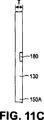
例えば、図11C−11Eは、ハウジング130の1実施の形態の斜視図、平面図、左側面図、右側面図及び正面図をそれぞれ示す。ハウジング130は、図11Bに示す外面131の寸法に比べて、図11C−11Eに示すように細長い厚みTを有する。1実施の形態では、厚みTは約10.27mmであり、外面は側部寸法S1とS2(これらは、それぞれ、142.33mmと124.86mmである)を有する。この実施の形態におけるハウジング130は、少なくとも部分的にCDケース又は他の円形ODケースに似た形に形成される。
For example, FIGS. 11C-11E show a perspective view, a plan view, a left side view, a right side view, and a front view, respectively, of one embodiment of the
図5−9は、円形ODセキュリティ装置102の一部の実施の形態の斜視図である。図10−13は他の実施の形態の円形ODセキュリティ装置102とその部分を示す図である。
5-9 is a perspective view of some embodiments of the circular
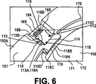
最初に図6を言及すると、この図は、1実施の形態による施錠装置110を含む円形ODセキュリティ装置102の一部を示す斜視図である。施錠装置110は磁力作動のラッチ112、フレキシブル・エレメント116及びラッチはめ込み要素118を含むことができる。
Reference is first made to FIG. 6, which is a perspective view of a portion of a circular
磁力作動のラッチ112は磁性体を含むことができ、また、図1の磁力作動のラッチ12に関して説明したように1つ以上の材料を含むことができる。さらに、1実施の形態において、フレキシブル・エレメント116を磁力作動のラッチ112に結合しまたはそれと一体的に形成することができる。1実施の形態において、フレキシブル・エレメント116を例えば板バネのように片持ち梁式アームの形状とすることができる。磁力作動のラッチ112はベース部113を含むことができ、ベース部113は、ベース部端113A及びベース部側面113B,113Cと;ラッチ部端114A(これはラッチはめ込み要素118と共に配置されるので、図6には示されていないが、図10に示されている)を含むことができるラッチ部114と;中心部115を含むことができる。
The magnetically actuated
磁力作動のラッチ112を「T」型のように形成することができる。したがって、ベース部側面113Bと113Cを平行とし、それぞれが少なくとも実際上まっすぐである。ベース部の側面113Bと113C間の距離であるベース部113の幅は、磁力作動のラッチが112の他の幅より広くすることができる。ベース部端113Aを平坦にしかつベース部側面113B,113Cに対して実質的に垂直とすることができる。磁力作動のラッチ112は細長い厚みを持つように構成されうる。しかしながら、磁力作動のラッチ112は、図1に示された磁力作動のラッチ12に関してここに説明されるように、別の様々な実施の形態として構成されうる。
The magnetically actuated
フレキシブル・エレメント116を可撓性材料から作ることができ、あるいは、可撓性材料を含むことができ、あるいは、図1に示されたフレキシブル・エレメント16に関してここで説明する材料を含むことができる。フレキシブル・エレメント116は、1実施の形態において、側部116Aが側部116Bより広いほぼ立方形の形を有するように構成される。他の様々な実施の形態では、フレキシブル・エレメント116は、図1の磁力作動のラッチ12に関して上で説明したように、1つ以上の材料のコイル他のスプリング又は同様な部材で構成され、あるいは、それを含むことができる。
The flexible element 116 can be made from a flexible material, or can include a flexible material, or can include the materials described herein with respect to the
以下で説明されるように、ラッチはめ込み要素118をハウジング130又はその一部と一体的に形成することとしてもよく、あるいは、分離した1つ又は複数のピースとすることができる。
As described below, the latch-
図7と12Aは、それぞれ、1実施の形態による円形ODセキュリティ装置102の以下に説明する底部ハウジング150と、セキュリティタグ120を示す斜視図である。図12Bは、図12Aの底部ハウジング150の部分Aの拡大図である。図7、12A、及び12Bに言及し、セキュリティタグ120は細長いEASタグ又はラベルである。他の様々な実施の形態では、セキュリティタグ120は、図1に示されたセキュリティタグ20に関してここに説明されるように、別のタイプ及び/又は形のセキュリティタグ又はラベルとされうる。エポキシの様な接着剤又は他の手段によりセキュリティタグ120を底部ハウジング150に取り付けることができる。他の様々な実施の形態において、セキュリティタグ120をOD又は他の物品の様々な表面上若しくは表面内に配置又は取り付けることができる。
7 and 12A are perspective views showing a
図2−13のそれぞれの実施の形態において少なくとも部分的に示される円形ODセキュリティ装置102のハウジング130はこの底部ハウジング150と、施錠装置カバー180と、セキュリティタグカバー190と、下カバー200と、上カバー205を含むことができる。1実施の形態では、ハウジング130のこれらの構成要素の1つ以上を分離構成要素とすることができる。他の様々な実施の形態では、構成要素の1つ以上の各組合せは、1個のピース、又は、不可分に1個のピースとして統合して取り付けられた複数のピースを含むことができる。ハウジング130のこれらの各構成要素は、様々な実施の形態において、プラスチック、別の材料、又は材料の組合せから作られうる。これらの構成要素は、様々な実施の形態では、同じ若しくは異なった材料又は材料の組合せを含むことができる。
The
図5と13Aは、1実施の形態による、セキュリティタグカバー190(以下で説明される)と、底部ハウジング150を示す斜視図である。図13Bは、図13の底部ハウジング150の拡大部Bを示す。図5及び図13A−13Bの実施の形態に言及し、底部ハウジング150は、底部ハウジング周辺壁150A乃至150Dによって形成される長方形の外形を有することができる。底部ハウジング150は、セキュリティタグ容器152を含むベース151と;湾曲内壁154と;円形ODはめ込み要素157及び空隙159を含む円形ODベース容器156を含む。セキュリティタグ容器152を底部ハウジング周辺壁150A及び150Dと、湾曲内部の壁154によって画成することができ、また、ここに説明されるように、細長いセキュリティタグ120と、セキュリティタグカバー190を受ける大きさに設けることができる。様々な実施の形態では、セキュリティタグ容器152の領域を大きくするためにハウジング周辺壁150Aと150C及び/又は150Bと150Dを細長くし、より大きい及び/又は異なる大きさのセキュリティタグ120をセキュリティタグ容器152内に納めるようにすることができる。
5 and 13A are perspective views illustrating a security tag cover 190 (described below) and a
円形OD容器156を底部ハウジング周辺壁150B乃至150Dの1つ以上と、かつ、できるだけ湾曲内壁154とも一体的にし、又は底部ハウジング150と堅固に結合することができる。
The
再び図6を参照して、この図は、また、底部ハウジング150の上部161の一部の実施の形態を示す斜視図である。上部161は、そこに磁力作動のラッチ112とフレキシブル・エレメント116を隣接して配置できるように構成される。その結果、磁力作動のラッチ112のベース部端113Aがフレキシブル・エレメント116の近く又はそれに接して置かれる。上部161のそのような構成により、磁力作動のラッチ112とフレキシブル・エレメント116の動きは1つ以上の方向に制限される。
Referring again to FIG. 6, this figure is also a perspective view showing an embodiment of a portion of the
例えば、底部ハウジング150の上部161は、チャンネル端壁165、チャネル壁166,168及びチャネル壁166,168によって画定されかつチャンネル端壁165により有界であるチャンネル164を含む。チャネル壁166,168は互いにほぼ平行な部分を含み、ベース部側面113B,112Cにおいて、かつ、中央部115とラッチ部114の側部において、磁力作動のラッチ112に接触して又はその近くに置かれ、その結果、磁力作動のラッチ112の動きをチャンネル164に沿った実質的に直線方向の動きに制限する。他の様々な実施の形態では、磁力作動のラッチ112は回転と直線方向を組合せた方向他の方向に動くことができる。これらの他の様々な実施の形態では、チャンネル164、フレキシブル・エレメント116及びラッチはめ込み要素118の1つ以上は磁力作動のラッチ112をそういった方向に案内するような外形を持ち、形状とされ、あるいは、構成される。
For example, the top 161 of the
フレキシブル・エレメント116をチャンネル端壁165に隣接して置き、磁力作動のラッチ112がロック位置から遠ざけられてフレキシブル・エレメント116に押しつけられたときに、磁力作動のラッチ112の力とチャンネル端壁165の抗力によりフレキシブル・エレメント116が圧縮されるように設けることができる。フレキシブル・エレメント116は、そのような圧縮、そのような磁力作動のラッチ112の動きに対して抗力を与える。
When the flexible element 116 is placed adjacent to the
上で説明した様々な実施の形態の各々において、磁力作動のラッチ112を別の形で構成することができ、その場合、チャンネル164、及び、引いては、チャネル壁166と168をそのような磁力作動のラッチ112を収容してその動きを1つ以上の方向に制限するように構成することができる。これらの各実施の形態では、フレキシブル・エレメント116は、チャンネル164内に嵌め込まれるように構成されるだろう。
In each of the various embodiments described above, the magnetically actuated
図10は1実施の形態による円形ODセキュリティ装置102の分解組立図を示す。この図10と、再び図5を参照して、底部ハウジング150の上部161は円形OD容器156の上部を含むことができる。円形OD容器156の上部は、ODはめ込み要素157と、盆地壁170と、盆地床171と、該盆地壁170及び盆地床171によって画定される盆地(ベースン、即ち、ODを受ける窪み)172を含む。ODはめ込み要素157は、底部ハウジング150と一体的に形成され空隙159を画定する1つ以上の片持ち梁式歯158を含む。複数の片持ち梁式歯158をプラスチックのような材料で作り、図示のごとく円形状に配列し、それらが内側に、即ち、空隙に向かって曲げられると弾性復元するように設けることができる。円形配列は、円形OD252の中央孔250などの円形ODの中央孔の半径と同じか大きい半径を有する外側境界を形成することができる。したがって、円形ODをそれらの片持ち梁式歯158の周りに配置して、締まりばめにより、該歯158、引いては、ODはめ込み要素157に固定することができる。円形ODを取り外すと、片持ち梁式歯158はそれらの曲げられる前の元の位置に戻る。1実施の形態では、片持ち梁式歯158の円形配列が円形ODの中央孔の半径よりも小さい半径を有する外側境界を形成するように設けることができる。
FIG. 10 shows an exploded view of the circular
他の様々な実施の形態では、ODはめ込み要素157を締まりばめ、押しばめ又は他の手段により円形ODの中央孔に係合する中実、中空又は歯を用いた、あるいは、その他の構造とすることができる。別の実施の形態では、円形OD容器156はODはめ込み要素157を含まない。
In various other embodiments, solid, hollow, or toothed or other structures that engage the center hole of the circular OD by interference fit, push fit or other means with the
円形ODを盆地壁170に接触させ又は接触させることなく、盆地172に合わせることができるように、盆地172を十分大きく形成するために、盆地壁170を円形他の形状に構成することができる。
To make the
底部ハウジング150の上部はまた、溝壁174−177と、これらの溝壁によって画定される湾曲溝174A−177A(177Aは見えないので、図10には示されていない)を含むことができる。例えば、溝壁174が含まれ、これは湾曲溝174Aを画定する。湾曲溝の174Aに隣接して、溝壁174の内部を「J」や「U」型のように形成することができる。溝壁175−177を含み、湾曲溝175A−177Aを含むことができる。湾曲溝174A−177Aを同様に又はほぼ同じに形成することができる。溝壁174−177をそれぞれ盆地壁170上に置き又はそれと一体的にすることができ、また、それらの溝壁互いに離間させそこで光ODを動かして盆地172に配置し又はそこから取り出すように設けることができる。
The top of the
再び図10と共に図6を参照して、底部ハウジング150の上部はまたラッチはめ込み要素118を含むことができる。ラッチはめ込み要素118を底部ハウジング150と一体的にして、チャネル壁166と168の間に延伸させ、そこから片持ち梁式に設けることができる。ラッチはめ込み要素118はラッチはめ込み要素壁118Aを含み、これは、フード118Bと、端壁118Cと、ラッチはめ込み要素壁118Aによって画定された凹み118Dとを有する。ラッチはめ込み要素壁118Aは、凹み118Dが上で説明した1つ以上の湾曲溝174A−177Aのように形成されるように構成される。
Referring again to FIG. 6 in conjunction with FIG. 10, the top of the
ラッチ部114と、磁力作動のラッチ112は、ロック位置にあるとき、フード118Bの下で延伸して凹み118Dの中まで延伸することができる。1実施の形態では、ラッチ部114と、磁力作動のラッチ112は凹み118Dを横切って端壁に118Cまで延伸する。
When in the locked position, the
ハウジング130はまた、図2−4及び10の実施の形態で示される施錠装置カバー180を含むことができる。施錠装置カバー180は、フレキシブル・エレメント116と、磁力作動のラッチ112の露出部分のように、ラッチ112の少なくとも一部の上に置かれるように構成された構造を含む、例えば、図10に示されるように、施錠装置カバー180は、チャンネル164内に配置された磁力作動のラッチ112の露出部分を囲むためにチャンネル164及び/又はチャネル壁166,168と協力するフード180Aと側壁180B,180Cを含む。施錠装置カバー180は、溶接、ハンダ付け、のり(接着剤)付け、押しばめ(例えば、チャネル壁166,168と施錠装置カバー180がはめ込み突起と空隙で構成される)、締まりばめ他の結合手段により底部ハウジング150に固定される。固定されると、施錠装置カバー180は、磁力作動のラッチ112を底部ハウジング150から取り外すことを防ぎ又は困難にする。
The
再び図5と図13A−13Bの実施の形態について言及し、ハウジング130はまた、セキュリティタグカバー190を含むことができる。セキュリティタグカバー190はセキュリティタグ120上に合うように構成されて、ハンダ付け、溶接、のり付け、テープ止め、機械的結合他の手段によりセキュリティタグ容器152内及び/又はセキュリティタグ120に固定される。
Referring again to the embodiment of FIGS. 5 and 13A-13B, the
図8を参照して、この図は、1実施の形態による円形ODセキュリティ装置102の下カバー200を示す斜視図である。下カバー200は、底部ハウジング150に固定されるように構成される。例えば、下カバー200は、下カバー周辺壁200A乃至200Dによって画定される角形とされ、かつ、下カバー周辺壁200A乃至200Dを底部ハウジング150の底部ハウジング周辺壁150A乃至150Dの周りに固定できるような大きさとされる。そのような固定は、押しばめ、接着剤、テープ止め及び/又は別の手段とすることができる。底部ハウジング150が異なる形状とされる実施の形態では、下カバー200は、それが底部ハウジング150に固定されるような補足的形状とされる。
Referring to FIG. 8, this figure is a perspective view showing a
下カバー200が底部ハウジング150に固定されているとき、セキュリティタグ120はそれにアクセスしたりそれを取り除いたりすることができないように包囲され、その中で固定される。
When the
図9は、1実施の形態による円形ODセキュリティ装置102の上カバー205を示す斜視図である。図2−4と図10の実施の形態と共に図9を参照すると、ハウジング130はまた上カバー205を含むことができる。上カバー205は上カバーベース207を含むことができ、上カバーベース207を中実にし、上カバー壁209により有界となるように構成することができる。上カバーベース207と上カバー壁209を円形とし、それらの大きさを上カバー壁209の内半径が円形ODの外半径より大きくなるように設けることができる。そのような場合、円形ODが上で説明されるように底部ハウジング150の盆地172の中に配置されると、上カバーベース207と上カバー壁209は、それぞれ、円形ODの上と周りに合って、円形ODをハウジング130の中に囲むことになる。
FIG. 9 is a perspective view showing the
上カバー205はさらに案内壁211乃至213を含むことができる。案内壁211−213を上カバー壁209から延伸させ、かつ、溝壁174−177と、ラッチはめ込み要素118(ラッチはめ込み要素壁118Aを含む)と協働する形状とすることができる。例えば、1実施の形態では、案内壁211−213をそれぞれ湾曲リップ211A−213Aを有する「L」形に上カバー壁209から延伸させることができる。湾曲リップは実質的に上カバー壁209に平行である。したがって、上で説明したように、上カバー205が円形ODの上と周りに合わされて円形ODをハウジング130の中に囲むと、案内壁211−213の湾曲リップ211A−213Aは、上カバー205が回転されると、それぞれ湾曲溝174A−177Aと、底部ハウジング150の凹み118Dの中を摺動する。
The
上カバー205は。ラッチはめ込み要素118が案内壁212と213の間に置かれるように円形OD上かつ底部ハウジング150上に置かれる。この位置において、案内壁212,213の湾曲リップ212A,213Aはそれぞれ、底部ハウジング150の湾曲溝174A,175Aの中に少なくとも部分的に置かれる。磁力作動のラッチ112がフレキシブル・エレメント116によってラッチはめ込み要素118の凹み118D内のロック位置に付勢されるので、磁力作動のラッチは、湾曲リップ212A,213Aが凹み118Dを通って摺動することを妨げる。そのような構成は上カバー205の制限された回転のみを許容し、その制限された回転内で、湾曲リップ211A−213Aの少なくとも1つが湾曲溝174A−177A内に少なくとも部分的に置かれ、それにより、上カバー205を底部ハウジング150に固定することができる。別の1実施の形態では、湾曲リップ211A−213Aは、その制限された回転範囲内で湾曲リップ211A−213Aの少なくとも2つがそれぞれ、湾曲溝174A−177A内に少なくとも部分的に置かれ、上カバー205をさらに底部ハウジング150に固定するように構成される。
The
種々の別の実施の形態において、上カバー205を底部ハウジング150に固定する機構を例えば以下に述べる方法の1つ又は2つ以上とするように変更可能である。即ち、底部ハウジング150は、さまざまな大きさに設けられかつ/又はすべての溝壁174−177、引いては、湾曲溝174A−177Aより少ないものを含むことができ、あるいは追加溝壁と湾曲溝を含むこととしてもよい;上カバー205は、さまざまな大きさに設けられかつ/又はすべての3つの案内壁211−213、引いては、湾曲リップ211A−213Aより少ないものを含むこととしてもよく;かつ/又は、底部ハウジング150の溝壁、溝、案内壁及びリップと、上カバー205の形状を変更することとしてもよい。このようにして、例えば、底部ハウジング150と上カバー205において溝壁、湾曲溝、案内壁及び湾曲リップの数とサイズを適当に構成して、上で説明されるように磁力作動のラッチ112がロック位置にあるときに、上カバー205を円形ODセキュリティ装置102の底部ハウジング150に固定できるようにすることができる。
In various other embodiments, the mechanism for securing the
別の実施の形態において、円形ODセキュリティ装置システムは円形ODセキュリティ装置102と、分離器40などの分離器を含む。フレキシブル・エレメント116が分離器40と磁力作動のラッチ112の間に位置されるように分離器40が円形ODセキュリティ装置102の磁力作動のラッチ112の近くに置かれると、分離器40は磁力作動のラッチ112を磁力によってロック位置から外してフレキシブル・エレメント116に押し付ける。磁力がフレキシブル・エレメント116の圧縮力と、磁力作動のラッチ112のそのような動きに抵抗するいかなる他の力より大きい場合、磁力作動のラッチ112はロック位置から外される。そのような場合は、上カバー205はもはや全回転拘束を受けず、上カバー205は自由に回転することができる。したがって、上カバー205は、そのいずれの湾曲リップ211A−213Aのいかなる部分が底部ハウジング150の湾曲溝174A−177A内に位置することがなくなるまで回転するので、上カバー205が取り外され、底部ハウジング150の盆地172の中に配置された円形ODをさらし出す。他の実施の形態として、上カバー205はヒンジ他の適当な構成により底部ハウジング150に回転可能に取り付けることとしてもよい。他の実施の形態では、上カバー205は、回転可能に固定され又は取り付けられるように、別の方法で固定され又は底部ハウジング150に固定されるだろう。この実施の形態において、解錠プロセスの間に、円形ODセキュリティ装置102のいかなる部分も壊されないので、円形ODセキュリティ装置102の再使用が可能である。
In another embodiment, the circular OD security device system includes a circular
1実施の形態では、円形ODセキュリティ装置102はCDを囲み又は含み、あるいは、そのように構成されて、CDセキュリティ装置102と呼ばれる。この実施の形態において、CDセキュリティ装置102は同様にいかなる他のタイプの円形ODも囲み又は含み、あるいは、そのように構成されうる。1実施の形態において、CDセキュリティ装置102のようなセキュリティ装置は、EASタグ、磁気機構及びいかなるタイプのCDも保持することができるだろう。このセキュリティ装置は、1実施の形態では、EAS構成要素と、セキュリティ装置で囲まれ又はそれに取り付けられたいかなるタイプのCDを担持し、権限のない者がCDセキュリティ装置を取ってそれを持って店を出ることに抵抗し又はそれを防ぐことに利用される。1実施の形態では、このセキュリティ装置は底部ハウジング、EASラベル、EASラベルカバー、下カバー、ラッチ機構カバー、磁力作動のラッチ機構及び上カバーを含む。1実施の形態では、円形ODセキュリティ装置102はこのセキュリティ装置を含むことができ、そこでは、施錠装置110が磁力作動のラッチ機構を含み、セキュリティタグ120がEASラベル又はタグを含み、ハウジング130が、それぞれ底部ハウジング150、セキュリティタグカバー190、下カバー200、施錠装置カバー180及び上カバー205に対応する底部ハウジングと、EASラベルカバーと、下カバーと、ラッチ機構カバーと、上カバーを含む複数の部分を含むことができる。
In one embodiment, the circular
ここに説明されるように実施の形態のある特徴が示されているが、当業者であれば、多くの変更、代替(置換)、変形例及び同等物を考えることができる。したがって、添付の特許請求の範囲は、実施の形態の範囲に包含されるそのようなすべての変更や変化をカバーすることを意図するものである。 Although certain features of the embodiments are illustrated as described herein, many modifications, alternatives (substitutions), variations, and equivalents may be considered by those skilled in the art. Accordingly, the appended claims are intended to cover all such modifications and changes as fall within the scope of the embodiments.
Claims (12)
セキュリティタグ(20)と、
磁気駆動施錠機構(10)と、
底部ハウジング(150)とを備え、前記セキュリティタグ(20)及び前記磁気駆動施錠機構(10)は該底部ハウジング(150)内に配置され、且つこの底部ハウジング(150)は光ディスク容器を含み、前記セキュリティ装置(2)は更に、前記光ディスク容器を包囲するように前記底部ハウジング(150)に固定された上カバー(205)を含んでなるセキュリティ装置において、
前記底部ハウジング(150)はチャンネル(3)を更に含み、前記磁気駆動施錠機構(10)は、磁気駆動ラッチ(112)と可撓要素(116)とを含み、これら磁気駆動ラッチ(112)及び可撓要素(116)は隣接されて配置され、且つ各々が少なくとも部分的に前記チャンネル(3)内に配設され、前記磁気駆動施錠機構は、ラッチはめ込み要素(118)を更に含み、このラッチはめ込み要素は凹みを規定し、前記底部ハウジング(150)は一つ又は複数の溝壁(174−177)を含み、その各々は弧状溝を規定し、前記セキュリティ装置は上カバー(205)を更に含み、この上 カバー(205)は一つ又は複数の案内壁(211−213)を含み、その各々は弧状リップ(211A−213A)を有し、その一つ又は複数の弧状リップ(211A−213A)のうちの一つの少なくとも一部分は、セキュリティ装置が係止されたときに一つ又は複数の弧状溝のうちの一つの少なくとも一部分内に位置し、前記ラッチはめ込み要素(118)は案内壁(211−213)の間に位置しているセキュリティ装置。A security device (2) for an optical disc (OD),
A security tag (20);
A magnetic drive locking mechanism (10);
A bottom housing (150), wherein the security tag (20) and the magnetically driven locking mechanism (10) are disposed within the bottom housing (150), and the bottom housing (150) includes an optical disc container, The security device (2) further comprises a top cover (205) secured to the bottom housing (150) so as to surround the optical disc container,
The bottom housing (150) further includes a channel (3), and the magnetic drive locking mechanism (10) includes a magnetic drive latch (112) and a flexible element (116), the magnetic drive latch (112) and The flexible elements (116) are disposed adjacent to each other and each is at least partially disposed within the channel (3), and the magnetically driven locking mechanism further includes a latch-fit element (118), the latch An inset element defines a recess, and the bottom housing (150) includes one or more groove walls (174-177), each of which defines an arcuate groove, and the security device further includes an upper cover (205). The upper cover (205) includes one or more guide walls (211 -213), each having an arcuate lip (211A-213A), one or At least a portion of one of the plurality of arcuate lips (211A-213A) is located in at least a portion of one of the one or more arcuate grooves when the security device is locked, and the latch-fit element (118) is a security device located between the guide walls (211 to 213).
Applications Claiming Priority (5)
| Application Number | Priority Date | Filing Date | Title |
|---|---|---|---|
| US63381304P | 2004-12-07 | 2004-12-07 | |
| US60/633,813 | 2004-12-07 | ||
| US68365705P | 2005-05-23 | 2005-05-23 | |
| US60/683,657 | 2005-05-23 | ||
| PCT/US2005/044689 WO2006063263A1 (en) | 2004-12-07 | 2005-12-07 | Optical disc security device having a magnetically actuable locking mechanism |
Publications (3)
| Publication Number | Publication Date |
|---|---|
| JP2008522920A JP2008522920A (en) | 2008-07-03 |
| JP2008522920A5 JP2008522920A5 (en) | 2009-03-12 |
| JP4792040B2 true JP4792040B2 (en) | 2011-10-12 |
Family
ID=36190454
Family Applications (5)
| Application Number | Title | Priority Date | Filing Date |
|---|---|---|---|
| JP2007545677A Ceased JP2008523509A (en) | 2004-12-07 | 2005-12-07 | Security device with cable |
| JP2007545675A Expired - Fee Related JP5046336B2 (en) | 2004-12-07 | 2005-12-07 | Bottle security device |
| JP2007545676A Expired - Fee Related JP4792040B2 (en) | 2004-12-07 | 2005-12-07 | Magnetically actuated locking device and related security device |
| JP2007545678A Expired - Fee Related JP4929185B2 (en) | 2004-12-07 | 2005-12-07 | Security equipment |
| JP2007545647A Pending JP2008533548A (en) | 2004-12-07 | 2005-12-07 | Security device for fixing articles with long elements |
Family Applications Before (2)
| Application Number | Title | Priority Date | Filing Date |
|---|---|---|---|
| JP2007545677A Ceased JP2008523509A (en) | 2004-12-07 | 2005-12-07 | Security device with cable |
| JP2007545675A Expired - Fee Related JP5046336B2 (en) | 2004-12-07 | 2005-12-07 | Bottle security device |
Family Applications After (2)
| Application Number | Title | Priority Date | Filing Date |
|---|---|---|---|
| JP2007545678A Expired - Fee Related JP4929185B2 (en) | 2004-12-07 | 2005-12-07 | Security equipment |
| JP2007545647A Pending JP2008533548A (en) | 2004-12-07 | 2005-12-07 | Security device for fixing articles with long elements |
Country Status (15)
| Country | Link |
|---|---|
| US (6) | US20080258478A1 (en) |
| EP (5) | EP1825088B1 (en) |
| JP (5) | JP2008523509A (en) |
| KR (5) | KR101237482B1 (en) |
| AT (3) | ATE506511T1 (en) |
| AU (5) | AU2005313915B2 (en) |
| BR (5) | BRPI0518369A2 (en) |
| CA (5) | CA2593740C (en) |
| DE (1) | DE602005027607D1 (en) |
| ES (2) | ES2380948T3 (en) |
| HK (5) | HK1113505A1 (en) |
| IL (5) | IL183559A0 (en) |
| MX (5) | MX2007006766A (en) |
| RU (5) | RU2405898C2 (en) |
| WO (5) | WO2006063262A1 (en) |
Families Citing this family (46)
| Publication number | Priority date | Publication date | Assignee | Title |
|---|---|---|---|---|
| US8054194B2 (en) | 2003-02-10 | 2011-11-08 | Autronic Plastics, Inc. | System and method for verifying a security status of a lockable container |
| US7724146B2 (en) * | 2004-11-17 | 2010-05-25 | Sensormatic Electronics, LLC | Magnetically releasable electronic article surveillance tag |
| US7961099B2 (en) | 2004-12-07 | 2011-06-14 | Sensormatic Electronics, LLC | Tamper-resistant article security device and method |
| ATE506511T1 (en) * | 2004-12-07 | 2011-05-15 | Sensormatic Electronics Llc | OPTICAL DISC SAFETY DEVICE HAVING A MAGNETICALLY ACTUATED LOCKING MECHANISM |
| US8264350B2 (en) | 2004-12-07 | 2012-09-11 | Sensormatic Electronics, LLC | Adjustable constraining adaptive insert for merchandise security tag and method thereof |
| AU2006251527B2 (en) * | 2005-05-23 | 2010-11-25 | Tyco Fire & Security Gmbh | Security device having a hooking element |
| AU2013213748B2 (en) * | 2006-08-25 | 2017-03-02 | Sensormatic Electronics Llc | Magnetically releasable electronic article surveillance tag |
| JP4942440B2 (en) * | 2006-09-29 | 2012-05-30 | 東洋製罐株式会社 | Cap with IC tag |
| JP2008090942A (en) * | 2006-10-03 | 2008-04-17 | Tdk Corp | Cartridge case and information recording medium |
| US8151606B2 (en) * | 2007-01-12 | 2012-04-10 | Autronic Plastics, Inc. | Fixed case automated decoupling device |
| US7772982B2 (en) * | 2007-05-04 | 2010-08-10 | Display Technologies, Inc. | Anti-theft tag |
| TWI344669B (en) * | 2007-06-27 | 2011-07-01 | Tank locking device, managerial system of liquid and method thereof | |
| EP2031165A1 (en) * | 2007-08-31 | 2009-03-04 | 3M Innovative Properties Company | Automatic unlocking system for CD/DVD cases |
| GB2454894A (en) * | 2007-11-22 | 2009-05-27 | Mainetti | Security device for use with a bottle |
| JP4946830B2 (en) * | 2007-11-28 | 2012-06-06 | Tdk株式会社 | Cartridge case and information recording medium |
| US8969950B2 (en) * | 2008-12-23 | 2015-03-03 | Alpha & Omega Semiconductor, Inc. | Integrated MOSFET-Schottky diode device with reduced source and body Kelvin contact impedance and breakdown voltage |
| JP5290791B2 (en) * | 2009-01-30 | 2013-09-18 | サトーホールディングス株式会社 | RFID tag holder |
| US8294583B2 (en) * | 2009-02-27 | 2012-10-23 | Universal Surveillance Corporation | Theft deterrent tag |
| US20100277323A1 (en) * | 2009-05-04 | 2010-11-04 | Display Technologies, Inc. | Anti-theft tag for an elongate member |
| US8986086B2 (en) * | 2009-05-14 | 2015-03-24 | Trw Automotive U.S. Llc | Insert for an opening |
| US8416082B2 (en) * | 2009-06-15 | 2013-04-09 | Universal Surveillance Corporation | Article surveillance tag |
| US9765551B2 (en) * | 2009-06-15 | 2017-09-19 | Universal Surveillance Corporation | Article surveillance tag |
| CN101868130B (en) * | 2010-03-26 | 2012-06-20 | 鸿富锦精密工业(深圳)有限公司 | Electronic device and buckle thereof |
| US9311797B2 (en) * | 2010-04-05 | 2016-04-12 | Wg Security Products | EAS tag for bottles |
| EP2590865B1 (en) * | 2010-07-09 | 2018-06-13 | B&G Plastics, Inc. | Tag for bottle neck having integral locking ring |
| EP2532815B1 (en) * | 2011-06-06 | 2020-07-15 | PLASTI-MAX SpA | Anti-theft device |
| US8616739B2 (en) * | 2011-06-08 | 2013-12-31 | Koninklijke Philips N.V. | Vandal resistant lighting fixture and method of manufacture thereof |
| FR2978283B1 (en) * | 2011-07-21 | 2014-01-17 | Thoonsen Trading | DEVICE FOR DISPLAYING PRICE INFORMATION FOR LIQUID CONTAINERS |
| USD751898S1 (en) | 2012-03-26 | 2016-03-22 | Abzac Canada Inc. | Cover for a container |
| FR2984945B1 (en) * | 2011-12-23 | 2014-01-10 | Solexxm | DETECTION, SIGNALING AND INFORMATION BADGE DEVICE, AND STARTER APPARATUS FOR SUCH A DEVICE. |
| US9070265B2 (en) | 2012-08-21 | 2015-06-30 | Tyco Fire & Security Gmbh | Security tag for application to footwear |
| US20140077954A1 (en) | 2012-09-20 | 2014-03-20 | Tyco Fire & Security Gmbh | Security tag for application to footwear |
| US20140091686A1 (en) * | 2012-10-02 | 2014-04-03 | Research In Motion Limited | Magnetic fastener apparatus and related methods |
| US9051097B1 (en) * | 2012-10-26 | 2015-06-09 | Richard J. Michiel | Apparatus for deterring and detecting tampering with a bottleneck cap of a bottle and method for the same |
| US8978427B2 (en) * | 2012-11-05 | 2015-03-17 | Tyco Fire & Security Gmbh | Tamper resistant security tag |
| US9579253B2 (en) | 2012-11-08 | 2017-02-28 | Grifols Worldwide Operations Limited | RFID tag and blood container/system with integrated RFID tag |
| US9607259B2 (en) * | 2013-02-27 | 2017-03-28 | B&G Plastics, Inc. | Tag housing asembly for attachment to a bottle neck |
| EP3005240B1 (en) | 2013-06-05 | 2018-08-29 | Haemonetics Corporation | Frangible rfid tag and method of producing same |
| EP3010816B1 (en) | 2013-06-18 | 2019-05-08 | Haemonetics Corporation | Rfid tag and method of securing same to object |
| BR112016008819B1 (en) | 2013-10-21 | 2022-04-19 | B&G Plastics, Inc | Assembly of electronic tag housing structure and electronic tag housing structure |
| KR200478493Y1 (en) * | 2015-04-09 | 2015-10-14 | (주)예원조경건설 | Smart directional sign |
| FR3052474B1 (en) * | 2016-06-08 | 2022-09-16 | Fors France | ANTI-THEFT DEVICE FOR CANS, CANS OR BOTTLES |
| US10643117B2 (en) * | 2017-08-23 | 2020-05-05 | Midwest Innovative Products, Llc | Electronic device for attachment to a beverage container |
| FR3086684B1 (en) * | 2018-10-02 | 2022-04-29 | Fors France | ANTI-THEFT DEVICE |
| US11358163B2 (en) * | 2019-08-07 | 2022-06-14 | Shawshank Ledz Inc. | Fan attachment to disposable containers and means for attachment |
| US11066851B2 (en) * | 2019-09-23 | 2021-07-20 | Sensormatic Electronics, LLC | Apparatus for removing a security tag from an article |
Citations (5)
| Publication number | Priority date | Publication date | Assignee | Title |
|---|---|---|---|---|
| JPH10228590A (en) * | 1997-02-17 | 1998-08-25 | Matsushita Electric Ind Co Ltd | Theft preventing device |
| JPH11193086A (en) * | 1997-10-16 | 1999-07-21 | Jii Tae Kim | Housing case for compact disk having theft preventive function |
| US6662950B1 (en) * | 1999-10-25 | 2003-12-16 | Brian R. Cleaver | Wafer shipping and storage container |
| JP2004059060A (en) * | 2001-12-10 | 2004-02-26 | Nisshin:Kk | Anti-theft device |
| US20040129587A1 (en) * | 2003-02-07 | 2004-07-08 | Lax Michael R. | Lockable container having an integral and internal locking mechanism and methods of use |
Family Cites Families (74)
| Publication number | Priority date | Publication date | Assignee | Title |
|---|---|---|---|---|
| US123657A (en) * | 1872-02-13 | Improvement in sash-holders | ||
| DE874568C (en) * | 1938-03-23 | 1953-04-23 | Alfred Harold Whiteley | Magnetic holding device, especially for doors and windows |
| US2719050A (en) * | 1951-08-30 | 1955-09-27 | Macy O Teetor | Magnetic catch |
| US2809062A (en) * | 1954-09-13 | 1957-10-08 | Mainhardt Robert | Latch mechanism |
| CH351186A (en) * | 1956-11-29 | 1960-12-31 | Schweiz Wagons Aufzuegefab | Magnetic door holder |
| US3057650A (en) * | 1959-09-21 | 1962-10-09 | Amerock Corp | Magnetic catch |
| FR1248654A (en) * | 1959-11-16 | 1960-12-23 | Magnetic catch with variable compensation | |
| US3589052A (en) * | 1969-04-15 | 1971-06-29 | Harold M King | Automatic sinker |
| US3657907A (en) * | 1970-03-06 | 1972-04-25 | Sievers Fa Carl | Lock, in particular padlock, with tumblers controlled by a magnetic key |
| FR2086962A5 (en) * | 1970-04-15 | 1971-12-31 | Berducone Dominique | |
| US3671065A (en) * | 1970-12-11 | 1972-06-20 | Amerock Corp | Slidable bolt catch |
| US3736779A (en) * | 1971-04-26 | 1973-06-05 | E Pratt | Lock |
| US3724889A (en) * | 1971-10-12 | 1973-04-03 | Gen Electric | Latching device |
| US3742739A (en) * | 1972-07-31 | 1973-07-03 | Orsi E | Magnetic lock |
| US3831986A (en) * | 1972-08-09 | 1974-08-27 | S Kobayashi | Container having magnetic and latch fastening means |
| US3770307A (en) * | 1972-09-14 | 1973-11-06 | Brammall Inc | Cable lock and seal device |
| US3974669A (en) * | 1975-08-25 | 1976-08-17 | American Locker Company, Inc. | Lock |
| US4194771A (en) * | 1978-05-15 | 1980-03-25 | Biggs Ronald L | Magnetic door stay retainer |
| DE3163406D1 (en) * | 1980-10-03 | 1984-06-07 | Kenwood Mfg Co Ltd | Magnetic door catches |
| US4457240A (en) * | 1982-06-25 | 1984-07-03 | Hungerford Robert E | Hand held and/or hard mounted weatherproof portable travel safe for full time protection of essential travel valuables |
| FR2606161B1 (en) * | 1986-11-03 | 1989-04-21 | Bouan Bruno | ANTI-THEFT DEVICE |
| EP0282678A1 (en) * | 1987-02-20 | 1988-09-21 | Etablissements Ed. Vaux | Anti-theft device for an article having at least a hook-in structure |
| FR2622547A1 (en) * | 1987-10-30 | 1989-05-05 | Actron Sa | Lockable support for safety circuit |
| US4825156A (en) * | 1988-03-30 | 1989-04-25 | Schwinn Bicycle Company | Signal detector for cycle computer with releasable strap frame mounting |
| US4848812A (en) * | 1988-04-08 | 1989-07-18 | Slaughter Steven J | Concealed safety lock |
| US5028083A (en) * | 1990-04-27 | 1991-07-02 | Motorola, Inc. | Latch assembly |
| IT1240918B (en) * | 1990-05-10 | 1993-12-23 | Costa Emilio Int Plast | ANTI-THEFT SEAL FOR COMMERCIAL ITEMS PRESENTING ASTIFORM PORTIONS |
| US5079540A (en) | 1990-09-06 | 1992-01-07 | Sensormatic Electronics Corporation | Theft detection tag with adjustable loop |
| US5062671A (en) * | 1990-11-05 | 1991-11-05 | Ibm Corporation | Door latch for a computer housing |
| AU619162B3 (en) * | 1991-04-23 | 1991-11-15 | M W Trading Aps | Lock mechanism |
| JPH0523205A (en) * | 1991-07-19 | 1993-02-02 | Takata Kk | Buckle in seat belt device |
| FR2702353B1 (en) * | 1993-03-12 | 1995-06-02 | Patrick Lamy | Anti-theft device for glasses. |
| SE505248C2 (en) * | 1993-03-12 | 1997-07-21 | Mw International Ltd | Theft protection for bottles |
| GB9306463D0 (en) * | 1993-03-29 | 1993-05-19 | Encrypta Electronics Ltd | Electronic seal |
| FR2704592B1 (en) * | 1993-04-30 | 1995-08-04 | Vaux Sylvie | Protection against shoplifting in stores. |
| US5485733A (en) * | 1993-05-13 | 1996-01-23 | Hoffman; Charles G. | Concealed magnetic lock for cabinet closure |
| FR2713379A1 (en) * | 1993-12-02 | 1995-06-09 | Wallet Claude | Sealing tie e.g. for container or suitcase |
| US5524463A (en) * | 1994-01-11 | 1996-06-11 | Sensormatic Electronics Corporation | Theft deterrent device to facilitate easy protection of large irregularly-shaped goods |
| FR2735895B1 (en) * | 1995-06-22 | 1997-10-24 | Fors France Sa | LOCKING SYSTEM IN PARTICULAR FOR ANTI-THEFT BOXES, CONCERNING THE PROTECTION OF PACKAGING, AUDIO AND VIDEO CASSETTES, ELECTRONIC GAMES AND C.D. |
| US5600977A (en) * | 1995-10-25 | 1997-02-11 | Pinel Medical Inc. | Magnetic locking device |
| US5969613A (en) * | 1997-08-11 | 1999-10-19 | Alpha Enterprises, Inc. | Electronic article surveillance security device |
| EP1049848B1 (en) * | 1998-01-29 | 2002-04-10 | NECCHI S.r.l. | Anti-theft case, particularly for compact disks, videocassettes, musicassettes and the like |
| KR100254878B1 (en) * | 1998-03-05 | 2000-05-01 | 안영광 | Burglarproof apparatus of compact disk |
| US5937487A (en) * | 1998-04-15 | 1999-08-17 | Bauer; Irving | Magnetic slide fastener |
| US6604643B1 (en) | 1998-06-24 | 2003-08-12 | Alpha Security Products, Inc. | Bottle security device |
| US6155615A (en) * | 1998-07-22 | 2000-12-05 | Ashland Products, Inc. | Tilt-latch for a sash window |
| US6137413A (en) * | 1998-10-29 | 2000-10-24 | Sensormatic Electronics Corporation | Cap with integrated eas marker |
| US6125668A (en) * | 1998-11-23 | 2000-10-03 | Alpha Enterprises, Inc. | Recorded media security container |
| AU5028399A (en) * | 1999-06-23 | 2001-01-31 | Emilio Costa | Anti-theft device for objects having tubular or otherwise substa ntially cylindrical portions |
| USD446118S1 (en) | 1999-06-23 | 2001-08-07 | Robert L. Michael | Bottle security closure |
| IT1307379B1 (en) * | 1999-08-06 | 2001-11-06 | Emilio Costa | ANTI-THEFT DEVICE FOR OBJECTS EQUIPPED WITH PORTIONS THAT CAN BE SURFACED BY FASCETTE OR SIMILAR. |
| US6578886B1 (en) * | 1999-09-20 | 2003-06-17 | Brammall, Inc. | Self-locking wire seal |
| US7257971B2 (en) * | 2000-07-31 | 2007-08-21 | Autronics Plastics Inc. | Case with internal lock |
| US6357091B1 (en) * | 1999-11-30 | 2002-03-19 | Trw Vehicle Safety Systems Inc. | Latch sensing seat belt buckle |
| NL1014308C2 (en) * | 2000-02-07 | 2001-08-08 | Boehaal B V | Safety packaging for a product to be displayed. |
| US6472989B2 (en) | 2000-02-29 | 2002-10-29 | Frederick H. Roy, Jr. | Child protection bracelet |
| GB0007985D0 (en) * | 2000-04-01 | 2000-05-17 | Plescon Ltd | Security device for a bottle |
| WO2001083325A2 (en) * | 2000-05-03 | 2001-11-08 | Alpha Security Products, Inc. | Security box for recorded media |
| JP3565162B2 (en) * | 2000-06-19 | 2004-09-15 | 株式会社日新 | Anti-theft device |
| WO2002002895A2 (en) * | 2000-06-30 | 2002-01-10 | Alpha Security Products, Inc. | Security storage container |
| US6624753B2 (en) * | 2001-01-30 | 2003-09-23 | World Color, Inc. | One piece snap close anti-theft hang tag for merchandise |
| US6543261B2 (en) * | 2001-07-13 | 2003-04-08 | B&G Plastics, Inc. | Article identification and security tag |
| US6631629B1 (en) * | 2001-07-30 | 2003-10-14 | Arthur Fuss | Anti-theft product tag with ball clutch |
| US6755055B2 (en) * | 2002-02-26 | 2004-06-29 | Alpha Security Products, Inc. | Theft deterrent device |
| US6726033B2 (en) * | 2002-05-14 | 2004-04-27 | Chicago Display Marketing Corporation | Clothes hanging and bagging rack |
| AUPS274202A0 (en) * | 2002-06-03 | 2002-06-20 | Cochlear Limited | Clothing attachment device for a speech processor of a cochlear implant |
| US6912878B2 (en) * | 2003-02-24 | 2005-07-05 | Alpha Security Products, Inc. | Bottle security device |
| USD506694S1 (en) * | 2003-08-14 | 2005-06-28 | Richard E. Corney | Theft deterrent strap |
| JP4764017B2 (en) * | 2004-02-27 | 2011-08-31 | 株式会社ジュエルパーツピコ | Trinkets for jewelry |
| US7266979B2 (en) * | 2004-07-30 | 2007-09-11 | Alpha Security Products, Inc. | Theft deterrent device |
| ATE506511T1 (en) * | 2004-12-07 | 2011-05-15 | Sensormatic Electronics Llc | OPTICAL DISC SAFETY DEVICE HAVING A MAGNETICALLY ACTUATED LOCKING MECHANISM |
| WO2006112022A1 (en) * | 2005-04-15 | 2006-10-26 | Fujitsu Limited | Lock device for foldable case, and electronic device provided with same |
| HK1076985A2 (en) * | 2005-10-10 | 2006-01-27 | Chi Pang Leung | Locking means for rolling shutter doors |
| US20070120377A1 (en) * | 2005-11-29 | 2007-05-31 | King Jeff A | Device for reversibly preventing closure of an overhead door |
-
2005
- 2005-12-07 AT AT05853571T patent/ATE506511T1/en not_active IP Right Cessation
- 2005-12-07 CA CA2593740A patent/CA2593740C/en not_active Expired - Fee Related
- 2005-12-07 WO PCT/US2005/044688 patent/WO2006063262A1/en active Application Filing
- 2005-12-07 JP JP2007545677A patent/JP2008523509A/en not_active Ceased
- 2005-12-07 RU RU2007125665A patent/RU2405898C2/en not_active IP Right Cessation
- 2005-12-07 MX MX2007006766A patent/MX2007006766A/en active IP Right Grant
- 2005-12-07 EP EP20050853573 patent/EP1825088B1/en not_active Not-in-force
- 2005-12-07 ES ES05853572T patent/ES2380948T3/en active Active
- 2005-12-07 AT AT05853572T patent/ATE544926T1/en active
- 2005-12-07 CA CA 2588918 patent/CA2588918C/en not_active Expired - Fee Related
- 2005-12-07 KR KR1020077015611A patent/KR101237482B1/en not_active IP Right Cessation
- 2005-12-07 MX MX2007006771A patent/MX2007006771A/en active IP Right Grant
- 2005-12-07 MX MX2007006769A patent/MX2007006769A/en active IP Right Grant
- 2005-12-07 CA CA2589398A patent/CA2589398C/en not_active Expired - Fee Related
- 2005-12-07 AU AU2005313915A patent/AU2005313915B2/en not_active Ceased
- 2005-12-07 RU RU2007125670A patent/RU2404344C2/en not_active IP Right Cessation
- 2005-12-07 JP JP2007545675A patent/JP5046336B2/en not_active Expired - Fee Related
- 2005-12-07 JP JP2007545676A patent/JP4792040B2/en not_active Expired - Fee Related
- 2005-12-07 MX MX2007006768A patent/MX2007006768A/en active IP Right Grant
- 2005-12-07 RU RU2007125630A patent/RU2404343C2/en not_active IP Right Cessation
- 2005-12-07 BR BRPI0518369-3A patent/BRPI0518369A2/en not_active IP Right Cessation
- 2005-12-07 AU AU2005313894A patent/AU2005313894B2/en not_active Ceased
- 2005-12-07 US US11/792,623 patent/US20080258478A1/en not_active Abandoned
- 2005-12-07 EP EP20050853571 patent/EP1825086B1/en not_active Not-in-force
- 2005-12-07 DE DE200560027607 patent/DE602005027607D1/en active Active
- 2005-12-07 AU AU2005313896A patent/AU2005313896B2/en not_active Ceased
- 2005-12-07 AU AU2005313893A patent/AU2005313893B2/en not_active Ceased
- 2005-12-07 RU RU2007125667A patent/RU2405900C2/en not_active IP Right Cessation
- 2005-12-07 AT AT05853573T patent/ATE510093T1/en not_active IP Right Cessation
- 2005-12-07 BR BRPI0518374-0A patent/BRPI0518374A2/en not_active Application Discontinuation
- 2005-12-07 KR KR1020077015609A patent/KR101273983B1/en not_active IP Right Cessation
- 2005-12-07 RU RU2007125711A patent/RU2405899C2/en not_active IP Right Cessation
- 2005-12-07 BR BRPI0518842-3A patent/BRPI0518842A2/en not_active IP Right Cessation
- 2005-12-07 EP EP20050853570 patent/EP1825085B1/en not_active Not-in-force
- 2005-12-07 JP JP2007545678A patent/JP4929185B2/en not_active Expired - Fee Related
- 2005-12-07 CA CA 2589412 patent/CA2589412C/en not_active Expired - Fee Related
- 2005-12-07 EP EP20050853448 patent/EP1825084A1/en not_active Withdrawn
- 2005-12-07 JP JP2007545647A patent/JP2008533548A/en active Pending
- 2005-12-07 US US11/792,632 patent/US8031073B2/en active Active
- 2005-12-07 AU AU2005313895A patent/AU2005313895B2/en not_active Ceased
- 2005-12-07 US US11/792,633 patent/US20080258479A1/en not_active Abandoned
- 2005-12-07 BR BRPI0518940-3A patent/BRPI0518940A2/en not_active Application Discontinuation
- 2005-12-07 US US11/792,647 patent/US8006524B2/en not_active Expired - Fee Related
- 2005-12-07 US US11/792,631 patent/US8089359B2/en not_active Expired - Fee Related
- 2005-12-07 ES ES05853570T patent/ES2424845T3/en active Active
- 2005-12-07 EP EP20050853572 patent/EP1825087B1/en not_active Not-in-force
- 2005-12-07 WO PCT/US2005/044691 patent/WO2006063265A1/en active Application Filing
- 2005-12-07 MX MX2007006767A patent/MX2007006767A/en active IP Right Grant
- 2005-12-07 CA CA 2588920 patent/CA2588920C/en not_active Expired - Fee Related
- 2005-12-07 KR KR1020077015562A patent/KR101363376B1/en active IP Right Grant
- 2005-12-07 WO PCT/US2005/044690 patent/WO2006063264A1/en active Application Filing
- 2005-12-07 BR BRPI0518832-6A patent/BRPI0518832A2/en not_active IP Right Cessation
- 2005-12-07 WO PCT/US2005/044689 patent/WO2006063263A1/en active Application Filing
- 2005-12-07 WO PCT/US2005/044524 patent/WO2006063190A1/en active Application Filing
- 2005-12-07 KR KR1020077015558A patent/KR101336854B1/en active IP Right Grant
-
2007
- 2007-05-30 IL IL183559A patent/IL183559A0/en unknown
- 2007-05-30 IL IL183558A patent/IL183558A0/en unknown
- 2007-06-07 IL IL183756A patent/IL183756A0/en unknown
- 2007-06-07 IL IL183758A patent/IL183758A0/en unknown
- 2007-06-07 IL IL183757A patent/IL183757A0/en unknown
- 2007-07-06 KR KR1020077015559A patent/KR101338040B1/en not_active IP Right Cessation
-
2008
- 2008-04-02 HK HK08103635A patent/HK1113505A1/en not_active IP Right Cessation
- 2008-04-02 HK HK08103638A patent/HK1113506A1/en not_active IP Right Cessation
- 2008-04-02 HK HK08103628A patent/HK1113504A1/en not_active IP Right Cessation
- 2008-04-09 HK HK08103943A patent/HK1114141A1/en not_active IP Right Cessation
- 2008-04-09 HK HK08103947A patent/HK1114142A1/en not_active IP Right Cessation
-
2011
- 2011-08-30 US US13/199,483 patent/US20110308284A1/en not_active Abandoned
Patent Citations (5)
| Publication number | Priority date | Publication date | Assignee | Title |
|---|---|---|---|---|
| JPH10228590A (en) * | 1997-02-17 | 1998-08-25 | Matsushita Electric Ind Co Ltd | Theft preventing device |
| JPH11193086A (en) * | 1997-10-16 | 1999-07-21 | Jii Tae Kim | Housing case for compact disk having theft preventive function |
| US6662950B1 (en) * | 1999-10-25 | 2003-12-16 | Brian R. Cleaver | Wafer shipping and storage container |
| JP2004059060A (en) * | 2001-12-10 | 2004-02-26 | Nisshin:Kk | Anti-theft device |
| US20040129587A1 (en) * | 2003-02-07 | 2004-07-08 | Lax Michael R. | Lockable container having an integral and internal locking mechanism and methods of use |
Also Published As
Similar Documents
| Publication | Publication Date | Title |
|---|---|---|
| JP4792040B2 (en) | Magnetically actuated locking device and related security device | |
| JP2014041619A (en) | Separator for security device | |
| US20040188286A1 (en) | Benefit denial systems for securing an asset within a container and methods of use | |
| CN101099016B (en) | Security device with magnetically actuable locking mechanism | |
| AU2012202003A1 (en) | Detacher for a security device | |
| AU2014218447B2 (en) | Detacher for a security device | |
| JP2001283339A (en) | Burglary prevention case |
Legal Events
| Date | Code | Title | Description |
|---|---|---|---|
| A521 | Request for written amendment filed |
Free format text: JAPANESE INTERMEDIATE CODE: A523 Effective date: 20081208 |
|
| A621 | Written request for application examination |
Free format text: JAPANESE INTERMEDIATE CODE: A621 Effective date: 20081208 |
|
| A521 | Request for written amendment filed |
Free format text: JAPANESE INTERMEDIATE CODE: A523 Effective date: 20090123 |
|
| TRDD | Decision of grant or rejection written | ||
| A01 | Written decision to grant a patent or to grant a registration (utility model) |
Free format text: JAPANESE INTERMEDIATE CODE: A01 Effective date: 20110705 |
|
| A01 | Written decision to grant a patent or to grant a registration (utility model) |
Free format text: JAPANESE INTERMEDIATE CODE: A01 |
|
| A61 | First payment of annual fees (during grant procedure) |
Free format text: JAPANESE INTERMEDIATE CODE: A61 Effective date: 20110722 |
|
| FPAY | Renewal fee payment (event date is renewal date of database) |
Free format text: PAYMENT UNTIL: 20140729 Year of fee payment: 3 |
|
| R150 | Certificate of patent or registration of utility model |
Free format text: JAPANESE INTERMEDIATE CODE: R150 |
|
| S111 | Request for change of ownership or part of ownership |
Free format text: JAPANESE INTERMEDIATE CODE: R313111 |
|
| R350 | Written notification of registration of transfer |
Free format text: JAPANESE INTERMEDIATE CODE: R350 |
|
| R250 | Receipt of annual fees |
Free format text: JAPANESE INTERMEDIATE CODE: R250 |
|
| S111 | Request for change of ownership or part of ownership |
Free format text: JAPANESE INTERMEDIATE CODE: R313113 Free format text: JAPANESE INTERMEDIATE CODE: R313111 |
|
| R360 | Written notification for declining of transfer of rights |
Free format text: JAPANESE INTERMEDIATE CODE: R360 |
|
| R360 | Written notification for declining of transfer of rights |
Free format text: JAPANESE INTERMEDIATE CODE: R360 |
|
| R371 | Transfer withdrawn |
Free format text: JAPANESE INTERMEDIATE CODE: R371 |
|
| S111 | Request for change of ownership or part of ownership |
Free format text: JAPANESE INTERMEDIATE CODE: R313113 Free format text: JAPANESE INTERMEDIATE CODE: R313111 |
|
| R350 | Written notification of registration of transfer |
Free format text: JAPANESE INTERMEDIATE CODE: R350 |
|
| LAPS | Cancellation because of no payment of annual fees |