JP4791734B2 - Telescopic boom of work vehicle - Google Patents
Telescopic boom of work vehicle Download PDFInfo
- Publication number
- JP4791734B2 JP4791734B2 JP2005019743A JP2005019743A JP4791734B2 JP 4791734 B2 JP4791734 B2 JP 4791734B2 JP 2005019743 A JP2005019743 A JP 2005019743A JP 2005019743 A JP2005019743 A JP 2005019743A JP 4791734 B2 JP4791734 B2 JP 4791734B2
- Authority
- JP
- Japan
- Prior art keywords
- boom
- guide member
- attached
- telescopic
- end side
- Prior art date
- Legal status (The legal status is an assumption and is not a legal conclusion. Google has not performed a legal analysis and makes no representation as to the accuracy of the status listed.)
- Active
Links
Images


Landscapes
- Jib Cranes (AREA)
- Forklifts And Lifting Vehicles (AREA)
Description
本発明は、高所作業車やクレーン車等の作業車において、作業台や懸吊装置の移動手段として走行体に取り付けて使用される作業車の伸縮ブームに関する。 The present invention relates to a telescopic boom of a work vehicle that is used by being attached to a traveling body as a moving means for a work table or a suspension device in a work vehicle such as an aerial work vehicle or a crane vehicle.
高所作業車やクレーン車等において作業台や懸吊装置等を移動する装置として従来伸縮ブームが用いられている。伸縮ブームは中空柱状で外径及び内径が順次小さくなる複数のブーム部材が入れ子式に構成されており、最も外径の大きい第1ブームが走行体に取り付けられている。第1ブームと走行体との間には油圧シリンダ(ブーム起伏シリンダ)が跨設されており、この油圧シリンダの伸縮作動によって伸縮ブーム全体を起伏動させることができるようになっている。また、伸縮ブームは内部に設けられた油圧シリンダ(ブーム伸縮シリンダ)の伸縮作動によって長手方向に伸縮動させることができるようになっている。伸縮ブームの伸縮形式には種々のものが知られているが、第1ブームと第2ブーム(第1ブームの次に外径及び内径の大きいブーム部材)との伸縮のみを油圧シリンダの作動によって行い、その他のブーム部材間の伸縮作動はブーム部材同士の間に設けられたプーリ・ワイヤ機構によって第1ブームと第2ブームとの間の伸縮作動と連動して行う形式のものが多く用いられている(例えば、下記の特許文献参照)。 Conventionally, a telescopic boom is used as a device for moving a work table, a suspension device or the like in an aerial work vehicle or a crane vehicle. The telescopic boom has a hollow columnar shape, and a plurality of boom members whose outer diameter and inner diameter are sequentially reduced are nested, and the first boom having the largest outer diameter is attached to the traveling body. A hydraulic cylinder (boom hoisting cylinder) is straddled between the first boom and the traveling body, and the entire telescopic boom can be raised and lowered by the telescopic operation of the hydraulic cylinder. The telescopic boom can be expanded and contracted in the longitudinal direction by an expansion and contraction operation of a hydraulic cylinder (boom telescopic cylinder) provided therein. Various types of expansion / contraction booms are known, but only the expansion / contraction of the first boom and the second boom (the boom member having the outer diameter and the inner diameter next to the first boom) is performed by the operation of the hydraulic cylinder. The other telescopic operation between the boom members is often performed in conjunction with the telescopic operation between the first boom and the second boom by a pulley / wire mechanism provided between the boom members. (For example, see the following patent document).
また、伸縮ブームの内部には、走行体側から作業機(高所作業車であれば作業台)側に各種信号を送信するための信号伝送ケーブルや作業機側へ圧油を供給するための送油ホースなどのライン状部材が通されている。このライン状部材は伸縮ブームの伸縮作動に応じて全体として伸縮するようにブーム部材の内部に配置されている。
しかしながら、従来においては伸縮ブームの内部に配置された油圧シリンダをライン状部材のブーム部材内における固定具として利用するなどしていたため、伸縮ブームの内部構造の修理やメンテナンス作業等において油圧シリンダを取り外すときにはライン状部材も取り外す必要があり、作業が複雑になって作業に要するコストが高くなるという問題があった。 However, in the past, the hydraulic cylinder disposed inside the telescopic boom has been used as a fixture in the boom member of the line-like member, and therefore, the hydraulic cylinder is removed for repair or maintenance work of the internal structure of the telescopic boom. In some cases, it is necessary to remove the line-shaped member, which causes a problem that the work becomes complicated and the cost required for the work increases.
本発明はこのような問題に鑑みてなされたものであり、内部構造の修理やメンテナンスを容易に行うことができ、これらの作業に対するコストを低減することが可能な構成の作業車の伸縮ブームを提供することを目的としている。 The present invention has been made in view of such a problem, and an extendable boom for a work vehicle having a configuration capable of easily repairing and maintaining an internal structure and reducing costs for these operations. It is intended to provide.
第1の本発明に係る作業車の伸縮ブームは、走行体に起伏動自在に取り付けられ、先端部に作業機(例えば、実施形態における作業台40)を有する作業車の伸縮ブームであって、第1ブーム、第2ブーム、第3ブーム及び第4ブームがこの順で入れ子式に構成され、第1ブームの基端部が走行体に取り付けられたブーム本体と、シリンダチューブ及びシリンダチューブに対して軸方向に相対移動自在なピストンロッドからなり、ブーム本体内においてシリンダチューブ及びピストンロッドの一方が第1ブームに取り付けられるとともに他方が第2ブームに取り付けられてブーム本体の軸線とほぼ平行に延びて設けられた油圧シリンダ(例えば、実施形態におけるブーム伸縮シリンダ52)と、油圧シリンダの伸縮作動により第2ブームが第1ブームに対して相対移動することに伴って、第3ブームを第2ブームに対して相対移動させるとともに第4ブームを第3ブームに対して相対移動させてブーム本体を軸線方向に伸縮作動させるブーム伸縮機構(例えば、実施形態におけるプーリ・ワイヤ機構)と、ブーム本体内においてブーム本体の基端側から先端側へ延びて設けられたライン状部材と、ブーム本体内において基端側が第3ブームに取り付けられて油圧シリンダの下方に位置してブーム本体の軸線とほぼ平行に延びるとともに、先端側に第4ブームの内周下面上を転動するローラ又は摺動する摺動部材を有したガイド部材と、基端部が第1ブームの内周下面に取り付けられるとともに先端部がガイド部材の基端側又は第3ブーム内に取り付けられ、内部にライン状部材を保護するとともにブーム本体の伸縮作動に伴って変形してライン状部材を案内する第1保護案内部材と、基端部がガイド部材の先端側又は第3ブーム内に取り付けられるとともに先端部が第4ブームの内周下面に取り付けられ、内部にライン状部材を保護するとともにブーム本体の伸縮作動に伴って変形してライン状部材を案内する第2保護案内部材とを備え、ライン状部材が、ブーム本体内における油圧シリンダの下方領域において、ブーム本体の基端側から第1保護案内部材、ガイド部材および第2保護案内部材の順にそれぞれにより案内されて前記ブーム本体の先端側へ延びて設けられる。
The telescopic boom of the work vehicle according to the first aspect of the present invention is a telescopic boom of a work vehicle that is attached to the traveling body so as to be able to move up and down and has a work machine (for example, the work table 40 in the embodiment) at the tip. The first boom, the second boom, the third boom, and the fourth boom are nested in this order, and the base end of the first boom is attached to the traveling body, and the cylinder tube and the cylinder tube. In the boom body, one of the cylinder tube and the piston rod is attached to the first boom and the other is attached to the second boom, and extends substantially parallel to the axis of the boom body. The hydraulic boom (for example, the boom
なお、上記構成の作業車の伸縮ブームにおいて、油圧シリンダの先端部にガイド部材の上面を転動するローラを有することが好ましい。Note that the telescopic boom of the work vehicle having the above-described configuration preferably has a roller that rolls on the upper surface of the guide member at the tip of the hydraulic cylinder.
また、第2の本発明に係る作業車の伸縮ブームは、走行体に起伏動自在に取り付けられ、先端部に作業機(例えば、実施形態における作業台40)を有する作業車の伸縮ブームであって、第1ブーム、第2ブーム、第3ブーム及び第4ブームがこの順で入れ子式に構成され、第1ブームの基端部が走行体に取り付けられたブーム本体と、シリンダチューブ及びシリンダチューブに対して軸方向に相対移動自在なピストンロッドからなり、ブーム本体内においてシリンダチューブ及びピストンロッドの一方が第1ブームに取り付けられるとともに他方が第2ブームに取り付けられてブーム本体の軸線とほぼ平行に延びて設けられた油圧シリンダ(例えば、実施形態におけるブーム伸縮シリンダ52)と、油圧シリンダの伸縮作動により第2ブームが第1ブームに対して相対移動することに伴って、第3ブームを第2ブームに対して相対移動させるとともに第4ブームを第3ブームに対して相対移動させてブーム本体を軸線方向に伸縮作動させるブーム伸縮機構(例えば、実施形態におけるプーリ・ワイヤ機構)と、ブーム本体内においてブーム本体の基端側から先端側へ延びて設けられたライン状部材と、ブーム本体内において基端側が第3ブームに取り付けられて油圧シリンダの上方に位置してブーム本体の軸線とほぼ平行に延びるとともに、先端側に第4ブームの内周下面上を転動するローラ又は摺動する摺動部材を有したガイド部材と、基端部が第1ブームの内周上面に取り付けられるとともに先端部がガイド部材の基端側又は第3ブーム内に取り付けられ、内部にライン状部材を保護するとともにブーム本体の伸縮作動に伴って変形してライン状部材を案内する第1保護案内部材と、基端部がガイド部材の先端側又は第3ブーム内に取り付けられるとともに先端部が第4ブームの内周上面に取り付けられ、内部にライン状部材を保護するとともにブーム本体の伸縮作動に伴って変形してライン状部材を案内する第2保護案内部材とを備え、ライン状部材が、ブーム本体内における油圧シリンダの上方領域において、ブーム本体の基端側から第1保護案内部材、ガイド部材および第2保護案内部材の順にそれぞれにより案内されてブーム本体の先端側へ延びて設けられる。
The telescopic boom of the work vehicle according to the second aspect of the present invention is a telescopic boom of a work vehicle that is attached to the traveling body so as to be able to move up and down and has a work machine (for example, the work table 40 in the embodiment) at the tip. A boom body in which the first boom, the second boom, the third boom, and the fourth boom are configured in a nested manner in this order, and the base end portion of the first boom is attached to the traveling body, the cylinder tube, and the cylinder tube consists relatively movable piston rod axially relative, substantially parallel to the other is attached to the second boom axis of the boom body with one of the cylinder tube and the piston rod is attached to the first boom in the boom The hydraulic cylinder (for example, the boom
なお、上記構成の作業車の伸縮ブームにおいて、油圧シリンダの先端部に第4ブームおよび第3ブームの内周下面上を転動するローラを有することが好ましい。In the telescopic boom of the work vehicle having the above-described configuration, it is preferable that the tip of the hydraulic cylinder has a roller that rolls on the inner peripheral lower surface of the fourth boom and the third boom.
また、上記構成の作業車の伸縮ブームにおいて、ブーム本体内において基端側が第2ブームに取り付けられるとともに先端側がブーム本体の伸縮作動に伴ってガイド部材に対してスライド移動自在にガイド部材に取り付けられ、上面において第1保護案内部材の中間部を支持する第2ガイド部材を備えることが好ましい。In the telescopic boom of the work vehicle having the above configuration, the base end side is attached to the second boom in the boom body, and the distal end side is attached to the guide member so as to be slidable with respect to the guide member in accordance with the telescopic operation of the boom body. It is preferable that a second guide member that supports an intermediate portion of the first protective guide member on the upper surface is provided.
第1の本発明に係る作業車の伸縮ブームでは、油圧シリンダはそれ自体単独でブーム本体に結合されており、ライン状部材は油圧シリンダの下方領域を延びて設けられている。このためガイド部材がブーム本体内に取り付けられている状態では、ブーム伸縮シリンダはライン状部材のブーム本体への取り付け状態とは無関係にブーム本体に対する着脱が可能であり、同様にライン状部材はブーム伸縮シリンダのブーム本体への取り付け状態とは無関係にブーム本体に対する着脱が可能である。このため伸縮ブームの内部構造の修理やメンテナンスを容易に行うことができ、これらの作業に要するコストを低減することが可能である。 In the telescopic boom of the work vehicle according to the first aspect of the present invention, the hydraulic cylinder is itself connected to the boom body alone, and the line member is provided extending in the lower region of the hydraulic cylinder. For this reason, in a state where the guide member is mounted in the boom body, the boom telescopic cylinder can be attached to and detached from the boom body regardless of the state in which the line-shaped member is mounted on the boom body. The telescopic cylinder can be attached to and detached from the boom body regardless of the state of attachment to the boom body. For this reason, repair and maintenance of the internal structure of the telescopic boom can be easily performed, and the cost required for these operations can be reduced.
第2の本発明に係る作業車の伸縮ブームでは、油圧シリンダはそれ自体単独でブーム本体に結合されており、ライン状部材は油圧シリンダの上方領域を延びて設けられている。このためガイド部材がブーム本体内に取り付けられている状態では、ブーム伸縮シリンダはライン状部材のブーム本体への取り付け状態とは無関係にブーム本体に対する着脱が可能であり、同様にライン状部材はブーム伸縮シリンダのブーム本体への取り付け状態とは無関係にブーム本体に対する着脱が可能である。このため伸縮ブームの内部構造の修理やメンテナンスを容易に行うことができ、第1の本発明に係る作業車の伸縮ブームと同様の効果を得ることができる。また、この第2の本発明に係る作業車の伸縮ブームでは、油圧シリンダをブーム本体の内周下面に近接して設けることができるので、伸縮ブーム全体の重心を低くすることが可能である。 In the telescopic boom of the work vehicle according to the second aspect of the present invention, the hydraulic cylinder is itself connected to the boom body alone, and the line-shaped member is provided extending in the upper region of the hydraulic cylinder. For this reason, in a state where the guide member is mounted in the boom body, the boom telescopic cylinder can be attached to and detached from the boom body regardless of the state in which the line-shaped member is mounted on the boom body. The telescopic cylinder can be attached to and detached from the boom body regardless of the state of attachment to the boom body. For this reason, repair and maintenance of the internal structure of the telescopic boom can be easily performed, and the same effect as the telescopic boom of the work vehicle according to the first aspect of the present invention can be obtained. Further, in the telescopic boom of the work vehicle according to the second aspect of the present invention, since the hydraulic cylinder can be provided close to the inner peripheral lower surface of the boom body, the center of gravity of the entire telescopic boom can be lowered.
以下、図面を参照して本発明の好ましい実施形態について説明する。図1は本発明に係る伸縮ブームを備えた高所作業車1を示している。この高所作業車1は走行用車輪11,11,・・・を備えて運転キャビン12から走行運転が可能なトラック式の走行体10と、走行体10上に設けられた旋回台20に起伏動自在に取り付けられた伸縮ブーム30と、伸縮ブーム30の先端部に取り付けられた作業者搭乗用の作業台40とを有して構成される。
Hereinafter, preferred embodiments of the present invention will be described with reference to the drawings. FIG. 1 shows an aerial work vehicle 1 equipped with a telescopic boom according to the present invention. This aerial work vehicle 1 is provided with traveling wheels 11,... That can be driven from a driving cabin 12, and a
旋回台20は走行体10の後部に上下軸まわり360度回動自在に取り付けられている。走行体10の内部にはブーム旋回モータ(油圧モータ)51が設けられており、このブーム旋回モータ51を回転作動させることにより、図示しないギヤを介して旋回台20を水平旋回させることができる。
The
伸縮ブーム30は中空柱状で順次外径及び内径が小さくなる複数のブーム部材(後述するように第1ブーム31a、第2ブーム31b、第3ブーム31c及び第4ブーム31d)が入れ子式に構成されており、その基端部が旋回台20の支柱21にフートピン22を介して取り付けられている。伸縮ブーム30の内部にはブーム伸縮シリンダ(油圧シリンダ)52が設けられており、このブーム伸縮シリンダ52を伸縮作動させることにより各ブーム部材を相対的に移動させて伸縮ブーム30全体を軸方向に伸縮させることができる。伸縮ブーム30と旋回台20の支柱21との間にはブーム起伏シリンダ(油圧シリンダ)53が跨設されており、このブーム起伏シリンダ53を伸縮作動させることにより伸縮ブーム30全体を起伏させることができる。
The
伸縮ブーム30の(第4ブーム31dの)先端部には垂直ポスト38が上方に延びて設けられており、作業台40はこの垂直ポスト38の上端部に設けられた作業台支持プレート39に対して水平旋回自在に取り付けられている。垂直ポスト38は伸縮ブーム30の先端部と作業台支持プレート39との間に介装されたレベリングシリンダ(油圧シリンダ)55の伸縮作動によって伸縮ブーム30の姿勢によらず常時垂直姿勢が保持されるようになっており、これにより作業台40の床面は常に水平姿勢が保たれるようになっている。なお、レベリングシリンダ55の伸縮作動は、図示しない傾き角度検出器によって検出される作業台40の水平姿勢からの傾き角度がほぼ零になるように制御装置(図示せず)によって自動制御される。
A
作業台40は平板状の床部材40a及びこの床部材40aの外周部に立設された手摺り40bとから構成されており、作業台支持プレート39内に設けられた作業台旋回モータ(油圧モータ)54を回転作動させることによって床部材40aを作業台支持プレート39に対して(すなわち垂直ポスト38に対して)水平旋回させることができる。 The work table 40 is composed of a flat floor member 40a and a handrail 40b erected on the outer periphery of the floor member 40a, and a work table turning motor (hydraulic motor) provided in the work table support plate 39. ) 54 can be pivoted horizontally with respect to the platform support plate 39 (ie, with respect to the vertical post 38).
作業台40には上部操作装置41が設置されており、作業台40に搭乗したオペレータ(作業者)OPはこの上部操作装置41に備えられたレバーやスイッチ等の操作手段の操作により伸縮ブーム30の起伏、伸縮、旋回操作と作業台40の水平旋回操作を行うことができ、自身の乗った作業台40を自在に移動させて高所での作業を行うことが可能である。なお、図1に示すように走行体10の前後左右計4箇所にはアウトリガジャッキ13が設けられており、作業を始める前にこれらアウトリガジャッキ13を接地させておくことにより走行体10の安定度を高めることができる。
An upper operation device 41 is installed on the work table 40, and an operator (operator) OP who has boarded the work table 40 operates the
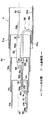
次に、図2〜図6を参照してこの高所作業車1に備えられた伸縮ブーム30の第1実施形態について説明する。第1実施形態に係る伸縮ブーム30は中空柱状で順次外径及び内径が小さくなる第1ブーム31a、第2ブーム31b、第3ブーム31c及び第4ブーム31dがこの順で入れ子式に構成されてなるブーム本体31及び前述のブーム伸縮シリンダ52のほか、ブーム本体31の内部に設置されたガイド部材32、ブーム本体31の内部をその基端側(走行体10側)から先端側(作業台40側)へ延びて設けられたライン状部材35及びこのライン状部材35を保護する2つの保護案内部材(第1保護案内部材36及び第2保護案内部材37)を有して構成される。
Next, a first embodiment of the
ブーム伸縮シリンダ52はブーム本体31の内部に、ブーム本体31の軸線AXと平行に延びて設けられている(図2参照)。ブーム伸縮シリンダ52は、シリンダチューブ52aとこのシリンダチューブ52aに対して軸方向に相対移動自在なピストンロッド52bからなっており、シリンダチューブ52aの端部(ブーム本体31の基端側の端部)は枢支ピンS1によって第2ブーム31bに、またピストンロッド52bの端部は枢支ピンS2によって第1ブーム31aに取り付けられている。このためブーム伸縮シリンダ52が伸縮作動すると第2ブーム31bが第1ブーム31aから引き出され、ブーム伸縮シリンダ52が収縮作動すると第2ブーム31bが第1ブーム31a内に格納される。
The boom
図2に示すように、第2ブーム31bに対する第3ブーム31cの相対移動及び第3ブーム31cに対する第4ブーム31dの相対移動はプーリ・ワイヤ機構によりなされる。このプーリ・ワイヤ機構は、シリンダチューブ52aの先端部(或いは第2ブーム31bの先端部)に取り付けられた第1プーリP1及びこの第1プーリP1に巻き掛けられて一端が第1ブーム31aの基端部に、他端が第3ブーム31cの基端部に取り付けられた第1ワイヤW1と、第3ブーム31cの先端部に取り付けられた第2プーリP2及びこの第2プーリP2に巻き掛けられて一端が第2ブーム31bの基端部に、他端が第4ブーム31dの基端部に取り付けられた第2ワイヤW2と、第2ブーム31bの基端部に取り付けられた第3プーリP3及びこの第3プーリP3に巻き掛けられて一端が第3ブーム31cの基端部に、他端が第1ブーム31aの先端部に取り付けられた第3ワイヤW3と、第3ブーム31cの基端部に取り付けられた第4プーリP4及びこの第4プーリP4に巻き掛けられて一端が第4ブーム31dの基端部に、他端が第2ブーム31bの先端部に取り付けられた第4ワイヤW4とから構成される。なお、上記プーリ・ワイヤ機構はブーム本体31の軸線AXを挟んで左右対称となるように2組設けられる。また、図2における4つのプーリP1,P2,P3,P4のブーム本体31に対する取り付け位置は図示の便宜上紙面の上下方向に並べて描いたに過ぎず、実際には第1プーリP1及び第3プーリP3はブーム伸縮シリンダ52の側方に設けられ、第2プーリP2は第1プーリP1の側方に(第2プーリP2の方が第1プーリP1よりもブーム本体31の先端側に位置する)、また第4プーリP4は第3プーリP3の側方にそれぞれ設けられる。
As shown in FIG. 2, the relative movement of the third boom 31c with respect to the second boom 31b and the relative movement of the
図2(A)に示すように、ブーム伸縮シリンダ52が全縮状態にあるときにはブーム本体31も全縮状態にある。この状態からブーム伸縮シリンダ52が伸長作動すると第2ブーム31bが第1ブーム31aから引き出され、これに伴って第3ブーム31cが第1プーリP1及び第1ワイヤW1の作用によって第2ブーム31bから引き出され、第4ブーム31dが第2プーリP2及び第2ワイヤW2の作用によって第3ブーム31cから引き出される(図2(B)参照)。また、この図2(B)に示す状態からブーム伸縮シリンダ52が収縮作動すると第2ブーム31bが第1ブーム31a内に格納され、これに伴って第3ブーム31cが第3プーリP3及び第3ワイヤW3の作用によって第2ブーム31b内に格納され、第4ブーム31dが第4プーリP4及び第4ワイヤW4の作用によって第3ブーム31c内に格納される。
As shown in FIG. 2A, when the boom
ガイド部材32は図3及び図4に示すように下方に開口した断面コの字形状の長尺状部材であり、一端側が第3ブーム31cに枢支ピンS3によって取り付けられてブーム伸縮シリンダ52の下方に位置し、ブーム本体31の軸線AXとほぼ平行に延びるとともに、ブーム本体31の(第4ブーム31dの)内周下面上を転動するローラR1を他端側に有している。なお、アーム32aはブーム本体31の幅方向に二股に分かれて2本延びており、ローラR1はこの二股に分かれた2本のアーム32それぞれに取り付けられている(後述するように、2本のアーム32aが第2保護案内部材37をその両側から跨ぐようにするため)。そして更に、このガイド部材32の上面を、ブーム伸縮シリンダ52の先端部に取り付けられたローラR2が転動自在になっている。なお、このブーム伸縮シリンダ52の先端部に取り付けられたローラR2は、シリンダチューブ52aの先端側の下方撓みを抑えるとともに、ブーム伸縮シリンダ52の自重の一部を支持することにより枢支ピンS1の過重負担を軽減する役割を果たしている。
ライン状部材35はブーム本体31の基端側(走行体側)から先端側(作業台40側)に各種信号を送信するための信号伝送ケーブルや作業台旋回モータ54は作業台40上で使用する油圧機器等に圧油を供給するための送油ホースなどからなっており、2つの保護案内部材(第1保護案内部材36及び第2保護案内部材37)により保護された状態で、ブーム伸縮シリンダ52の下方領域を延びて設けられている。
The line-shaped
ライン状部材35を保護する2つの保護案内部材、すなわち第1保護案内部材36及び第2保護案内部材37はライン状部材35を衝撃等から保護するとともに、ブーム本体31の伸縮に伴ってライン状部材35がブーム本体31内を整然と移動するようにこれを案内する働きをする。これら両保護案内部材36,37は図5に示すように中空矩形断面形状のリンク部材Lが結合ピンCにより連続的に結合された構成を有しており、ライン状部材35はこれらリンク部材Lの内部空間内を延びて設けられている。
Two protective guide members for protecting the line-shaped
第1保護案内部材36は、一端部(ライン状部材35に沿った走行体10側の端部36a)が第1ブーム31aの内周下部に取り付けられてブーム本体31内をその基端側に延びた後、上方に反転してブーム本体31の先端側に延び(反転部を符号36cとして示す)、他端部(ライン状部材35に沿った作業台40側の端部36b)がガイド部材32におけるブーム本体31の基端側の端部に(或いは第3ブーム31cであってもよい。但しガイド部材32よりも下方の領域に)取り付けられている。また第2保護案内部材37は、一端部(ライン状部材35に沿った走行体10側の端部37a)がガイド部材32の先端側に取り付けられてブーム本体31内をその基端側に延びた後、下方に反転してブーム本体31の先端側に延び(反転部を符号37cとして示す)、他端部(ライン状部材35に沿った作業台40側の端部37b)が第4ブーム31dの内周下部に取り付けられている。
The first
ライン状部材35は第1保護案内部材36及び第2保護案内部材37それぞれに対して固定されており、ブーム本体31が伸縮して第1保護案内部材36及び第2保護案内部材37が変形するときにはライン状部材35もこれら両保護案内部材36,37と一体となって変形するようになっている。ライン状部材35のうち第1保護案内部材36よりも走行体10側に位置する部分35aは第1保護案内部材36の両側部を延びるように配置された状態で第1ブーム31aの内周下面に固定されており、第2保護案内部材37よりも作業台40側に位置する部分35bは第4ブーム31dの内周下面に固定されている。また、ライン状部材35のうち第1保護案内部材36と第2保護案内部材37との間の部分35cは、図3、図6及び図4に示すようにガイド部材32の左右の側壁32bに設けられた穴32c,32dから側壁32bの外方を延びてここに(側壁32bに)固定されている。なお、第2保護案内部材37及びライン状部材35のうち第2保護案内部材37よりも作業台40側に位置する部分35bは2つのローラR1の間を延びて(すなわち2本のアーム32aが第2保護案内部材37及びライン状部材35を跨ぐように)設けられる。これにより第4ブーム31dの内周下面におけるガイド部材32の2つのローラR1の転動路が確保される。
The line-shaped
ここで、ブーム本体31が全縮の状態(図3参照)から伸縮シリンダ52を伸長作動させると、第2ブーム31bは第1ブーム31aに対して、第3ブーム31cは第2ブーム31bに対して、また第4ブーム31dは第3ブーム31cに対してそれぞれ相対移動してブーム本体31全体が伸長する(図6参照)。このときガイド部材32のローラR1は第4ブーム31dの内周下面上を転動するので、ガイド部材32はブーム本体31の軸線AXに対する平行姿勢が維持される。また、ブーム伸縮シリンダ52のローラR2はこのガイド部材32の上面を転動するのでブーム伸縮シリンダ52もブーム本体31の軸線AXに対する平行姿勢が維持される。第1保護案内部材36の端部36bと第2保護案内部材37の端部37aとはブーム本体31の伸長によってそれぞれ第1ブーム31aから離れる方向に移動するが、これら2つの端部36b,37aはともに第3ブーム31cに対して固定された状態となっているので、2つの端部36b,37aの相対位置は変化しない。
Here, when the
このように第1実施形態における伸縮ブーム30では、ブーム伸縮シリンダ52はそれ自体単独で(2つの枢支ピンS1,S2によって)ブーム本体31に結合されており、ライン状部材35は2つの保護案内部材(第1保護案内部材36及び第2保護案内部材37)により保護された状態でブーム伸縮シリンダ52の下方領域を延びて設けられている。このためガイド部材32がブーム本体31内に取り付けられている状態では、ブーム伸縮シリンダ52はライン状部材35のブーム本体31への取り付け状態とは無関係にブーム本体31に対する着脱が可能であり、同様にライン状部材35はブーム伸縮シリンダ52のブーム本体31への取り付け状態とは無関係にブーム本体31に対する着脱が可能である。このため伸縮ブーム30の内部構造の修理やメンテナンスを容易に行うことができ、これらの作業に要するコストを低減することが可能である。
As described above, in the
続いて、図7〜図9を参照して第2実施形態に係る伸縮ブーム130について説明する。第2実施形態に係る伸縮ブーム130は第1実施形態と同じ構成を有するブーム本体31、ブーム伸縮シリンダ52、ライン状部材135のほか、ライン状部材135を保護する2つの保護案内部材(第1保護案内部材136及び第2保護案内部材137)、ブーム本体31の内部に設置された第1ガイド部材132及び第2ガイド部材133を有して構成される。
Next, the
ブーム伸縮シリンダ52は第1実施形態の場合と同様、ブーム本体31の内部に、ブーム本体31の軸線AXとほぼ平行に延びるように取り付けられるが、第1実施形態の場合とは異なり、ブーム伸縮シリンダ52の下方領域には何も設けられないため、ブーム伸縮シリンダ52はブーム本体31の内周下面に近接して設けることができる(図7参照)。この第2実施形態でもブーム伸縮シリンダ52はシリンダチューブ52aの端部(ブーム本体31の基端側の端部)が枢支ピンS1によって第2ブーム31bに、またピストンロッド52bの端部が枢支ピンS2によって第1ブーム31aに取り付けられる。このためブーム伸縮シリンダ52が伸縮作動すると第2ブーム31bが第1ブーム31aに対して相対移動することとなり、第2ブーム31bが第1ブーム31aから引き出されるのは第1実施形態の場合と同じである。また、ブーム伸縮シリンダ52の先端部に設けられたローラR2は第4ブーム31d及び第3ブーム31cの内周下面上を転動自在になっており、第1実施形態の場合と同様に、シリンダチューブ52aの先端側の下方撓みを抑えるとともに、ブーム伸縮シリンダ52の自重の一部を支持することにより枢支ピンS1の過重負担を軽減することができるようになっている。また、第2ブーム31bに対する第3ブーム31cの相対移動及び第3ブーム31cに対する第4ブーム31dの相対移動はプーリ・ワイヤ機構によりなされるのも第1実施形態の場合と同様であり、その構成も第1実施形態の場合と同じであるのでその説明は省略する。
The boom
第1ガイド部材132は図7及び図8に示すように上方に開口した断面コの字形状の長尺状部材であり、一端側が第3ブーム31cに枢支ピンS3によって取り付けられてブーム伸縮シリンダ52の上方に位置し、ブーム本体31の軸線AXとほぼ平行に延びるとともに、第4ブーム31dの内周下面上を転動するローラR1を他端側に有している。但し、ローラR1を支持するアーム132aは、必ずしも第1実施形態の場合のように二股にする必要はない。第2ガイド部材133も第1ガイド部材132と同様に上方に開口した断面コの字形状の長尺状部材であるが(図7及び図8参照)、第1ガイド部材132を下方から支持し得るように、第1ガイド部材132よりもひと回り大きいサイズを有している。そして、一端側の端部が第2ブーム31bに枢支ピンS4によって取り付けられてブーム伸縮シリンダ52の上方に位置し、ブーム本体31の軸線AXと略平行に延びるとともに、他端側に設けられて上方に延びる係止部133aを、第1ガイド部材132の両側に上方に延びて設けられたサイド部132b(図8参照)に係止させている。
The
ライン状部材135の構成は第1実施形態のライン状部材35と同じであるが、本実施形態では、2つの保護案内部材(第1保護案内部材136及び第2保護案内部材137)により保護された状態で、ブーム伸縮シリンダ52の上方領域を延びて設けられている。
The configuration of the line-shaped
第1保護案内部材136は、一端部(ライン状部材135に沿った走行体10側の端部136a)が第1ブーム31aの先端側内周上部に取り付けられてブーム本体31内をその基端側に延びた後、下方に反転してブーム本体31の先端側に延び(反転部を符号136cとして示す)、他端部(ライン状部材135に沿った作業台40側の端部136b)が第1ガイド部材132の上面側に(第3ブーム31cであってもよい。但し第1ガイド部材132よりも上方の領域に)取り付けられている。また、第2保護案内部材137は、一端部(ライン状部材135に沿った走行体10側の端部137a)が第1ガイド部材132の先端側上面に取り付けられてブーム本体31内をその基端側に延びた後、上方に反転してブーム本体31の先端側に延び(反転部を符号137cとして示す)、他端部(ライン状部材135に沿った作業台40側の端部137b)が第4ブーム31dの内周上部に取り付けられている。
The first
ライン状部材135は第1保護案内部材136及び第2保護案内部材137それぞれに対して固定されており、ブーム本体31が伸縮して第1保護案内部材136及び第2保護案内部材137が変形するときにはライン状部材135もこれら両保護案内部材136,137と一体となって変形するようになっているのは第1実施形態の場合と同じである。また、ライン状部材135のうち第1保護案内部材136よりも走行体10側に位置する部分135aは第1保護案内部材136の両側部を延びるように配置された状態で第1ブーム31aの内周上面に固定されており、第2保護案内部材137よりも作業台40側に位置する部分135bは第2保護案内部材137の先端より延びるように配置された状態で第4ブーム31dの内周上面に固定されている。また、第1保護案部材136と第2保護案内部材137との間の部分135cは第2保護案内部材137の両側部を延びるように配置されている(図8参照)。
The line-shaped
ここで、ブーム本体31が全縮の状態(図7参照)から伸縮シリンダ52を伸長作動させると、第2ブーム31bは第1ブーム31aに対して、第3ブーム31cは第2ブーム31bに対して、また第4ブーム31dは第3ブーム31cに対してそれぞれ相対移動してブーム本体31全体が伸長する(図9参照)。このときブーム伸縮シリンダ52のローラR2は第4ブーム31d及び第3ブーム31cの内周下面上を転動するので、ブーム伸縮シリンダ52はブーム本体31の軸線AXに対する平行姿勢が維持される。また、ガイド部材132もローラR1が第4ブーム31dの内周下面上を転動することによってブーム本体31の軸線AXに対する平行姿勢が維持される。第1保護案内部材136の端部136bと第2保護案内部材137の端部137aとはブーム本体31の伸長によってそれぞれ第1ブーム31aから離れる方向に移動するが、これら2つの端部136b,137aはともに第3ブーム31cに対して固定された状態となっているので、2つの端部136b,137aの相対位置は変化しない。
Here, when the
また、第1ガイド部材132と第2ガイド部材133とはブーム本体31の軸線AX方向に相対移動するが、第2ガイド部材133の係止部133aは第1ガイド部材132のサイド部132bに対してスライド移動できるため、第2ガイド部材133もブーム本体31の軸線AXに対する平行姿勢が維持される。そして、第1保護案内部材136はこの第2ガイド部材133の上面において支持されるため、ブーム本体31の伸長によって第1保護案内部材136の中間部が下方に弛んできても、これがブーム伸縮シリンダ52と接触することはない。
Further, the
上記のように第2実施形態に係る伸縮ブーム130では、ブーム伸縮シリンダ52はそれ自体単独で(2つの枢支ピンS1,S2によって)ブーム本体31に結合されており、また、ライン状部材135は2つの保護案内部材(第1保護案内部材136及び第2保護案内部材137)により保護された状態でブーム伸縮シリンダ52の上方領域を延びて設けられている。このため第1ガイド部材132がブーム本体31内に取り付けられている状態では、ブーム伸縮シリンダ52はライン状部材135のブーム本体31への取り付け状態とは無関係にブーム本体31に対する着脱が可能であり、同様にライン状部材135はブーム伸縮シリンダ52のブーム本体31への取り付け状態とは無関係にブーム本体31に対する着脱が可能である。このため伸縮ブーム130の内部構造の修理やメンテナンスを容易に行うことができ、第1実施形態と同様の効果を得ることができる。また、この第2実施形態に係る伸縮ブーム130では、ブーム伸縮シリンダ52をブーム本体31の内周下面に近接して設けることができるので、伸縮ブーム130全体の重心を低くすることが可能である。なお、上述の実施形態において示した第2ガイド部材137は第1保護案内部材136の下方への弛みを支えてこれがブーム伸縮シリンダ52に接触しないようにするためのものであるので、他の手段によって弛みを抑えることができるような場合には不要となる。
As described above, in the
これまで本発明の好ましい実施形態について説明してきたが、本発明の範囲は上述の実施形態に示したものに限定されない。例えば、上述の第1実施形態において示したライン状部材35の配置は一例に過ぎず、ブーム伸縮シリンダ52の下方領域を延びて設けられているのであれば、その配置形態は(第1保護案内部材36や第2保護案内部材37などの保護案内部材が必要か否か、必要とするならばその設置形態をどのようにするかなども含めて)任意である。また、上述の第2実施形態において示したライン状部材135の配置も一例であり、ブーム伸縮シリンダ52の上方領域を延びて設けられているのであれば、その配置形態は(第1保護案内部材136や第2保護案内部材137などの保護案内部材が必要か否か、必要とするならばその設置形態をどのようにするかなども含めて)任意である。また、上述の2つの実施形態では、ブーム伸縮シリンダ52はシリンダチューブ52aが第2ブーム31bに取り付けられ、ピストンロッド52bが第1ブーム31aに取り付けられる構成であったが、これらを逆にし、シリンダチューブ52aが第1ブーム31aに取り付けられ、ピストンロッド52bが第2ブーム31bに取り付けられる構成とすることも可能である。
The preferred embodiments of the present invention have been described so far, but the scope of the present invention is not limited to those shown in the above-described embodiments. For example, the arrangement of the line-shaped
また、上述の2つの実施形態において示した、第4ブーム31dの内周下面上を転動するローラR1は、第4ブーム31dの内周下面上を摺動する摺動部材(スライダなど)に替えることが可能である。また、上述の実施形態では、本発明が適用される伸縮ブームは入れ子式に構成されるブーム部材が4つである4段ブームであったが、4段よりも多い段数を有する伸縮ブームについても応用することが可能である。例えば、4段よりも多い段数を有する伸縮ブームにおける中間の4つの隣接したブーム部材について本発明を適用することもできる。また、上述の実施形態では本発明が適用される作業車が伸縮ブームの先端部に作業台を備える高所作業車であったが、本発明は伸縮ブームの先端部に懸吊装置を備えたクレーン車やアースオーガを備えた穴掘り建柱車等にも同様に適用することが可能である。
In addition, the roller R 1 that rolls on the inner peripheral lower surface of the
1 高所作業車(作業車)
10 走行体
30 伸縮ブーム
31 ブーム本体
31a 第1ブーム
31b 第2ブーム
31c 第3ブーム
31d 第4ブーム
32 ガイド部材
35 ライン状部材
36 第1保護案内部材
37 第2保護案内部材
40 作業台(作業機)
52 ブーム伸縮シリンダ(油圧シリンダ)
52a シリンダチューブ
52b ピストンロッド
130 伸縮ブーム
132 第1ガイド部材(ガイド部材)
133 第2ガイド部材
135 ライン状部材
136 第1保護案内部材
137 第2保護案内部材
1 High-altitude work vehicle (work vehicle)
DESCRIPTION OF
52 Boom telescopic cylinder (hydraulic cylinder)
133
Claims (5)
第1ブーム、第2ブーム、第3ブーム及び第4ブームがこの順で入れ子式に構成され、前記第1ブームの基端部が前記走行体に取り付けられたブーム本体と、
シリンダチューブ及び前記シリンダチューブに対して軸方向に相対移動自在なピストンロッドからなり、前記ブーム本体内において前記シリンダチューブ及び前記ピストンロッドの一方が前記第1ブームに取り付けられるとともに他方が前記第2ブームに取り付けられて前記ブーム本体の軸線とほぼ平行に延びて設けられた油圧シリンダと、
前記油圧シリンダの伸縮作動により前記第2ブームが前記第1ブームに対して相対移動することに伴って、前記第3ブームを前記第2ブームに対して相対移動させるとともに前記第4ブームを前記第3ブームに対して相対移動させて前記ブーム本体を前記軸線方向に伸縮作動させるブーム伸縮機構と、
前記ブーム本体内において前記ブーム本体の基端側から先端側へ延びて設けられたライン状部材と、
前記ブーム本体内において基端側が前記第3ブームに取り付けられて前記油圧シリンダの下方に位置して前記軸線とほぼ平行に延びるとともに、先端側に前記第4ブームの内周下面上を転動するローラ又は摺動する摺動部材を有したガイド部材と、
基端部が前記第1ブームの内周下面に取り付けられるとともに先端部が前記ガイド部材の基端側又は前記第3ブーム内に取り付けられ、内部に前記ライン状部材を保護するとともに前記ブーム本体の伸縮作動に伴って変形して前記ライン状部材を案内する第1保護案内部材と、
基端部が前記ガイド部材の先端側又は前記第3ブーム内に取り付けられるとともに先端部が前記第4ブームの内周下面に取り付けられ、内部に前記ライン状部材を保護するとともに前記ブーム本体の伸縮作動に伴って変形して前記ライン状部材を案内する第2保護案内部材とを備え、
前記ライン状部材が、前記ブーム本体内における前記油圧シリンダの下方領域において、前記ブーム本体の基端側から前記第1保護案内部材、前記ガイド部材および前記第2保護案内部材の順にそれぞれにより案内されて前記ブーム本体の先端側へ延びて設けられたことを特徴とする作業車の伸縮ブーム。 A telescopic boom of a work vehicle that is attached to a traveling body so as to freely move up and down, and has a work machine at a tip part,
A boom body in which a first boom, a second boom, a third boom, and a fourth boom are configured to be nested in this order, and a base end portion of the first boom is attached to the traveling body;
The cylinder tube and a piston rod that is movable relative to the cylinder tube in the axial direction are configured such that one of the cylinder tube and the piston rod is attached to the first boom in the boom body and the other is the second boom. A hydraulic cylinder attached to and extending substantially parallel to the axis of the boom body;
As the second boom moves relative to the first boom by the expansion and contraction operation of the hydraulic cylinder, the third boom moves relative to the second boom and the fourth boom moves to the second boom. A boom telescopic mechanism for moving the boom body in the axial direction by moving relative to the three booms;
A line-shaped member provided extending from the base end side of the boom main body to the front end side in the boom main body;
Together with the base end side is attached to the third boom is located below the hydraulic cylinder extend substantially parallel to the axis in the boom body, rolling the fourth boom inner peripheral lower surface above the front end side A guide member having a roller or a sliding member to slide;
A base end portion is attached to the inner peripheral lower surface of the first boom, and a tip end portion is attached to the base end side of the guide member or the third boom to protect the line-shaped member therein and A first protective guide member that is deformed in accordance with an expansion and contraction operation and guides the line-shaped member;
A proximal end is attached to the distal end side of the guide member or inside the third boom, and a distal end is attached to the inner peripheral lower surface of the fourth boom, protecting the line-shaped member inside and expanding and contracting the boom body. A second protective guide member that deforms along with the operation and guides the line-shaped member;
The line-shaped member is guided by the first protection guide member, the guide member, and the second protection guide member in this order from the base end side of the boom body in a region below the hydraulic cylinder in the boom body. telescopic boom of a work vehicle, characterized in that provided extending toward the distal end side of the base boom Te.
第1ブーム、第2ブーム、第3ブーム及び第4ブームがこの順で入れ子式に構成され、前記第1ブームの基端部が前記走行体に取り付けられたブーム本体と、
シリンダチューブ及び前記シリンダチューブに対して軸方向に相対移動自在なピストンロッドからなり、前記ブーム本体内において前記シリンダチューブ及び前記ピストンロッドの一方が前記第1ブームに取り付けられるとともに他方が前記第2ブームに取り付けられて前記ブーム本体の軸線とほぼ平行に延びて設けられた油圧シリンダと、
前記油圧シリンダの伸縮作動により前記第2ブームが前記第1ブームに対して相対移動することに伴って、前記第3ブームを前記第2ブームに対して相対移動させるとともに前記第4ブームを前記第3ブームに対して相対移動させて前記ブーム本体を前記軸線方向に伸縮作動させるブーム伸縮機構と、
前記ブーム本体内において前記ブーム本体の基端側から先端側へ延びて設けられたライン状部材と、
前記ブーム本体内において基端側が前記第3ブームに取り付けられて前記油圧シリンダの上方に位置して前記軸線とほぼ平行に延びるとともに、先端側に前記第4ブームの内周下面上を転動するローラ又は摺動する摺動部材を有したガイド部材と、
基端部が前記第1ブームの内周上面に取り付けられるとともに先端部が前記ガイド部材の基端側又は前記第3ブーム内に取り付けられ、内部に前記ライン状部材を保護するとともに前記ブーム本体の伸縮作動に伴って変形して前記ライン状部材を案内する第1保護案内部材と、
基端部が前記ガイド部材の先端側又は前記第3ブーム内に取り付けられるとともに先端部が前記第4ブームの内周上面に取り付けられ、内部に前記ライン状部材を保護するとともに前記ブーム本体の伸縮作動に伴って変形して前記ライン状部材を案内する第2保護案内部材とを備え、
前記ライン状部材が、前記ブーム本体内における前記油圧シリンダの上方領域において、前記ブーム本体の基端側から前記第1保護案内部材、前記ガイド部材および前記第2保護案内部材の順にそれぞれにより案内されて前記ブーム本体の先端側へ延びて設けられたことを特徴とする作業車の伸縮ブーム。 A telescopic boom of a work vehicle that is attached to a traveling body so as to freely move up and down, and has a work machine at a tip part,
A boom body in which a first boom, a second boom, a third boom, and a fourth boom are configured to be nested in this order, and a base end portion of the first boom is attached to the traveling body;
The cylinder tube and a piston rod that is movable relative to the cylinder tube in the axial direction are configured such that one of the cylinder tube and the piston rod is attached to the first boom in the boom body and the other is the second boom. A hydraulic cylinder attached to and extending substantially parallel to the axis of the boom body;
As the second boom moves relative to the first boom by the expansion and contraction operation of the hydraulic cylinder, the third boom moves relative to the second boom and the fourth boom moves to the second boom. A boom telescopic mechanism for moving the boom body in the axial direction by moving relative to the three booms;
A line-shaped member provided extending from the base end side of the boom main body to the front end side in the boom main body;
Together with the base end side is attached to the third boom is located above the hydraulic cylinder extend substantially parallel to the axis in the boom body, rolling the fourth boom inner peripheral lower surface above the front end side A guide member having a roller or a sliding member to slide;
A base end portion is attached to the inner peripheral upper surface of the first boom, and a tip end portion is attached to the base end side of the guide member or the third boom to protect the line-shaped member therein and A first protective guide member that is deformed in accordance with an expansion and contraction operation and guides the line-shaped member;
A base end portion is attached to the distal end side of the guide member or in the third boom, and a distal end portion is attached to the inner peripheral upper surface of the fourth boom to protect the line-shaped member inside and extend and contract the boom body. A second protective guide member that deforms along with the operation and guides the line-shaped member;
The line-shaped member, in the upper region of the hydraulic cylinder in the boom body, the first protective guide member from the base end of the boom body is guided by the respective order of said guide member and said second protective guide member telescopic boom of a work vehicle, characterized in that provided extending toward the distal end side of the base boom Te.
Priority Applications (1)
| Application Number | Priority Date | Filing Date | Title |
|---|---|---|---|
| JP2005019743A JP4791734B2 (en) | 2005-01-27 | 2005-01-27 | Telescopic boom of work vehicle |
Applications Claiming Priority (1)
| Application Number | Priority Date | Filing Date | Title |
|---|---|---|---|
| JP2005019743A JP4791734B2 (en) | 2005-01-27 | 2005-01-27 | Telescopic boom of work vehicle |
Publications (3)
| Publication Number | Publication Date |
|---|---|
| JP2006206242A JP2006206242A (en) | 2006-08-10 |
| JP2006206242A5 JP2006206242A5 (en) | 2007-12-06 |
| JP4791734B2 true JP4791734B2 (en) | 2011-10-12 |
Family
ID=36963510
Family Applications (1)
| Application Number | Title | Priority Date | Filing Date |
|---|---|---|---|
| JP2005019743A Active JP4791734B2 (en) | 2005-01-27 | 2005-01-27 | Telescopic boom of work vehicle |
Country Status (1)
| Country | Link |
|---|---|
| JP (1) | JP4791734B2 (en) |
Families Citing this family (4)
| Publication number | Priority date | Publication date | Assignee | Title |
|---|---|---|---|---|
| KR101141666B1 (en) * | 2009-12-24 | 2012-05-04 | 주식회사 에프원텍 | Boom structure for high place works car |
| ITTO20100316A1 (en) * | 2010-04-19 | 2011-10-20 | Merlo Project Srl | AIRCRAFT BOAT FOR LIFTING VEHICLES |
| JP5141734B2 (en) * | 2010-09-03 | 2013-02-13 | コベルコ建機株式会社 | Boom piping structure of work machine |
| CN112850520A (en) * | 2021-02-20 | 2021-05-28 | 三一汽车起重机械有限公司 | Oil cylinder guide mechanism, telescopic arm and engineering machinery |
Family Cites Families (2)
| Publication number | Priority date | Publication date | Assignee | Title |
|---|---|---|---|---|
| JPH0812268A (en) * | 1994-06-29 | 1996-01-16 | Aichi Corp | Device for holding line member of telescopic boom |
| JP2002104793A (en) * | 2000-09-29 | 2002-04-10 | Aichi Corp | Telescopic boom |
-
2005
- 2005-01-27 JP JP2005019743A patent/JP4791734B2/en active Active
Also Published As
| Publication number | Publication date |
|---|---|
| JP2006206242A (en) | 2006-08-10 |
Similar Documents
| Publication | Publication Date | Title |
|---|---|---|
| US10989332B2 (en) | Internally supported power track | |
| JP5140303B2 (en) | Counterweight mounting device | |
| JP5006622B2 (en) | Crane device with telescopic boom | |
| JP4791734B2 (en) | Telescopic boom of work vehicle | |
| US8800716B2 (en) | Adjustable work platform for pipe and casing stabbing operations | |
| KR970007462B1 (en) | Carrier track assembly for extensible and retractable boom machines | |
| JP7086454B2 (en) | Telescopic boom | |
| JP4580768B2 (en) | Telescopic boom | |
| JP7287030B2 (en) | Telescopic cylinder assembly for telescopic boom | |
| JP6569311B2 (en) | Jib overhang storage mechanism | |
| WO2016194267A1 (en) | Overhanging storage mechanism for jib | |
| JP5145064B2 (en) | Boom structure | |
| JP2951205B2 (en) | Hose holding structure of multi-stage telescopic boom | |
| JP3853149B2 (en) | Telescopic boom | |
| JP7393340B2 (en) | Pivotally connected telescopic crane boom | |
| JP4174309B2 (en) | Telescopic boom | |
| JP4068042B2 (en) | Work vehicle control device | |
| JP4264311B2 (en) | Telescopic boom | |
| JP2000177991A (en) | Elongated/contracted boom device | |
| JP4885493B2 (en) | Telescopic boom | |
| JPH0812268A (en) | Device for holding line member of telescopic boom | |
| JP2009012871A (en) | Telescopic boom | |
| JP7467237B2 (en) | Road-rail vehicles | |
| JP7401358B2 (en) | Installation structure of boom hoisting position detection device | |
| JP6807733B2 (en) | Aerial work platform |
Legal Events
| Date | Code | Title | Description |
|---|---|---|---|
| A521 | Request for written amendment filed |
Free format text: JAPANESE INTERMEDIATE CODE: A523 Effective date: 20071022 |
|
| A621 | Written request for application examination |
Free format text: JAPANESE INTERMEDIATE CODE: A621 Effective date: 20071022 |
|
| A977 | Report on retrieval |
Free format text: JAPANESE INTERMEDIATE CODE: A971007 Effective date: 20100528 |
|
| A131 | Notification of reasons for refusal |
Free format text: JAPANESE INTERMEDIATE CODE: A131 Effective date: 20101119 |
|
| A521 | Request for written amendment filed |
Free format text: JAPANESE INTERMEDIATE CODE: A523 Effective date: 20110113 |
|
| TRDD | Decision of grant or rejection written | ||
| A01 | Written decision to grant a patent or to grant a registration (utility model) |
Free format text: JAPANESE INTERMEDIATE CODE: A01 Effective date: 20110708 |
|
| A01 | Written decision to grant a patent or to grant a registration (utility model) |
Free format text: JAPANESE INTERMEDIATE CODE: A01 |
|
| A61 | First payment of annual fees (during grant procedure) |
Free format text: JAPANESE INTERMEDIATE CODE: A61 Effective date: 20110722 |
|
| FPAY | Renewal fee payment (event date is renewal date of database) |
Free format text: PAYMENT UNTIL: 20140729 Year of fee payment: 3 |
|
| R150 | Certificate of patent or registration of utility model |
Ref document number: 4791734 Country of ref document: JP Free format text: JAPANESE INTERMEDIATE CODE: R150 |
|
| R250 | Receipt of annual fees |
Free format text: JAPANESE INTERMEDIATE CODE: R250 |
|
| R250 | Receipt of annual fees |
Free format text: JAPANESE INTERMEDIATE CODE: R250 |
|
| R250 | Receipt of annual fees |
Free format text: JAPANESE INTERMEDIATE CODE: R250 |
|
| R250 | Receipt of annual fees |
Free format text: JAPANESE INTERMEDIATE CODE: R250 |
|
| R250 | Receipt of annual fees |
Free format text: JAPANESE INTERMEDIATE CODE: R250 |
|
| R250 | Receipt of annual fees |
Free format text: JAPANESE INTERMEDIATE CODE: R250 |
|
| R250 | Receipt of annual fees |
Free format text: JAPANESE INTERMEDIATE CODE: R250 |
|
| R250 | Receipt of annual fees |
Free format text: JAPANESE INTERMEDIATE CODE: R250 |
|
| R250 | Receipt of annual fees |
Free format text: JAPANESE INTERMEDIATE CODE: R250 |
|
| R250 | Receipt of annual fees |
Free format text: JAPANESE INTERMEDIATE CODE: R250 |