JP4790657B2 - Work machine boom - Google Patents
Work machine boom Download PDFInfo
- Publication number
- JP4790657B2 JP4790657B2 JP2007120300A JP2007120300A JP4790657B2 JP 4790657 B2 JP4790657 B2 JP 4790657B2 JP 2007120300 A JP2007120300 A JP 2007120300A JP 2007120300 A JP2007120300 A JP 2007120300A JP 4790657 B2 JP4790657 B2 JP 4790657B2
- Authority
- JP
- Japan
- Prior art keywords
- boom
- upper half
- lower half
- cylinder
- divided
- Prior art date
- Legal status (The legal status is an assumption and is not a legal conclusion. Google has not performed a legal analysis and makes no representation as to the accuracy of the status listed.)
- Expired - Fee Related
Links
Images


Description
本発明は、下ブームと中ブームと上ブームとにより構成される多関節ブームの先端に、破砕、切断、散水等のための作業具を取付けた解体機等の作業機械に係り、特にその保管、輸送のための分解、組立構造に関する。 The present invention relates to a work machine such as a dismantling machine in which a work tool for crushing, cutting, sprinkling, etc. is attached to the tip of an articulated boom composed of a lower boom, a middle boom, and an upper boom. , Disassembly for transportation, and assembly structure.
コンクリート建造物の解体を行なう解体機のブームは、ブームの先端に取付ける破砕具、切断具、散水具またはこれらの複合機能を有する作業具等を高所に到達可能とするため、長尺の多関節ブームが採用される。この多関節ブームは、一般的には比較的長尺の下ブームおよび上ブームと、これら上下のブームより短い1本または複数本の中ブームとから構成され、各ブーム間の関節部に、上側に隣接するブームを回動させるブームシリンダが取付けられる。また、一般的には、下ブームや上ブームは建物の高さや種類に対応するため、それぞれ継ぎ足し可能に構成される。 The demolition machine boom that dismantles concrete buildings is a long, multi-purpose machine that can be used to reach high places such as crushing tools, cutting tools, watering tools, or work tools that have these combined functions. Joint boom is adopted. This articulated boom is generally composed of a relatively long lower boom and upper boom, and one or a plurality of middle booms shorter than the upper and lower booms. A boom cylinder is mounted for rotating the boom adjacent to. In general, the lower boom and the upper boom are configured so that they can be added to each other in order to correspond to the height and type of the building.
このような下ブーム、中ブーム、上ブームからなるブームにおいては、これが長尺であるため、そのままではトレーラ輸送が困難であり、輸送にあたって本体から分解し、かつ各ブーム間を適宜分解して輸送し、作業現場において組み立てることが行なわれる。また、保管時には、保管スペースの節約および取り扱いの容易化のため、やはり分解して保管することが行なわれる。 In such a boom composed of a lower boom, a middle boom, and an upper boom, since this is long, it is difficult to transport the trailer as it is. Assembling is performed at the work site. Also, during storage, disassembly and storage are also performed to save storage space and facilitate handling.
このような中ブームを有する多関節ブームの場合、各ブーム間に設けられるブームシリンダをブームから外して輸送、保管すると、ブームシリンダのブームに対する分解、組立作業に多大の労力と手間がかかる。そこでブームシリンダのブームに対する分解、組立作業を不要とするため、特許文献1においては、中ブームを下半部と上半部とに分解可能に構成し、輸送の際には中ブームを下半部と上半部とに分解可能にすると共に、中ブームと下ブームとの間のブームシリンダは下半部と下ブームの先端側分割ブームに連結したままとし、かつ中ブームと上ブームとの間のブームシリンダも上半部と上ブームの基端側分割ブームに連結したままとして輸送可能としている。
In the case of such an articulated boom having an intermediate boom, if the boom cylinder provided between the booms is removed from the boom and transported and stored, much effort and labor are required for disassembling and assembling the boom cylinder. Therefore, in order to eliminate the need for disassembling and assembling the boom cylinder, in
上述した従来のブーム構造によれば、輸送や保管または現場作業を開始するにあたり、中ブームと下ブームまたは上ブームとの間の関節部に設けるブームシリンダのブームに対する分解、組立作業は不要になるものの、中ブームの分解および組立を行なわなければならないため、やはり分解、組立作業に手間、労力がかかるという問題点がある。また、分解状態でのブーム構成部材の部品点数が多くなるため、トラックの台数を多く必要とするという問題点がある。 According to the above-described conventional boom structure, when starting transportation, storage, or field work, disassembly and assembly work of the boom cylinder provided at the joint between the middle boom and the lower boom or the upper boom is not required. However, since the middle boom must be disassembled and assembled, there is still a problem that it takes time and effort to disassemble and assemble. Moreover, since the number of parts of the boom constituent member in the disassembled state increases, there is a problem that a large number of trucks are required.
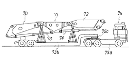
一方、図11に示すように、下ブームの先端側分割ブーム70、中ブーム71、上ブームの基端側分割ブーム72を縦に連結し、かつ各ブーム間のブームシリンダ73、74を連結したままで輸送する場合がある。しかしこの輸送構造においては、トラック本体75aと荷台75bとが旋回可能な接続装置75cを介して結合されたトレーラトラック75に搭載して輸送する必要があり、輸送費がかかり、輸送も容易ではないという問題点がある。
On the other hand, as shown in FIG. 11, the lower boom distal end
本発明は、上記問題点に鑑み、輸送や保管または現場作業を開始するにあたり、分解、組立の手間、労力が削減され、短時間で容易に分解、組立が可能になると共に、比較的小型でかつ少ない台数のトラックを用いて輸送することが可能となり、輸送の面でも容易化、経済化が可能となる作業機械のブームを提供することを目的とする。 In view of the above problems, the present invention reduces the labor and labor of disassembling and assembling when starting transportation, storage or on-site work, enables easy disassembling and assembling in a short time, and is relatively small. An object of the present invention is to provide a boom for a working machine that can be transported using a small number of trucks and that can be easily and economically transported.
請求項1の作業機械のブームは、自走式車両の旋回体に多関節ブームをブームシリンダにより俯仰動可能に取付け、
前記多関節ブームは、分割可能な継ぎ足し式ブームでなる下ブームと、分割可能な継ぎ足し式ブームでなる上ブームと、前記下ブームと前記上ブームとを連結する中ブームとを備え、各関節部に設けるブームシリンダにより回動可能に連結して構成すると共に、上ブームの先端に作業具を取付けてなる作業機械において、
前記中ブームを下半部と上半部とにより構成し、前記多関節ブームの起立状態における前記下半部の前面側と前記分割可能な継ぎ足し式下ブームのうち前記下半部に隣接する下ブームの前面側とを第1のブームシリンダで連結すると共に、
前記多関節ブームの起立状態における前記上半部の前面側と前記分割可能な継ぎ足し式上ブームのうち前記上半部に隣接する上ブームの前面側とを第2のブームシリンダで連結し、
前記下半部と前記上半部の一方の側面側にそれぞれブラケットを設けてそのブラケット同士をピンにより結合し、他方の側面側同士を結合部材により着脱可能に結合し、
前記他方の側面側の結合部材による結合を解くことにより、前記下半部に対して前記上半部が前記ピン中心に回動可能となるように構成し、
前記下半部と前記上半部とを前記一方の側面側のピンを中心に回動させて折畳んだ際に前記一方の側面側を互いに対面させると共に、前記第1および第2のブームシリンダを短縮させた際に前記下半部と前記上半部とが結合した状態で、それぞれの合わせ面が下側を向くように前記下半部と前記上半部の合わせ面を形成したことを特徴とする。
The boom of the work machine according to
The articulated boom comprises a lower boom made of divisible topped Boom, a boom top made of divisible topped Boom, and a boom in which connecting the on the boom and the lower boom, the joint In a working machine in which a work cylinder is configured to be pivotally connected by a boom cylinder provided in the upper boom, and a work tool is attached to the tip of the upper boom.
It said in boom constituted by a lower half and an upper half portion, the lower adjacent the said lower half portion of the articulated boom wherein the splittable topped formula under the boom and the front side of the lower half portion in the upright position of together when connecting the front face side of the boom in the first boom cylinder,
Wherein a front side of the boom top adjacent to the upper half of the splittable topped formula on the boom and the front side of the upper half in the upright position of the articulated boom connected by a second boom cylinder,
Brackets are provided on one side of the lower half and the upper half, respectively, and the brackets are coupled by pins, and the other side is detachably coupled by a coupling member,
The upper half is configured to be rotatable about the pin with respect to the lower half by releasing the coupling by the coupling member on the other side surface,
When the lower half and the upper half are folded around a pin on the one side, the one side faces each other and the first and second boom cylinders When the lower half and the upper half are joined together, the mating surfaces of the lower half and the upper half are formed so that each mating surface faces downward. Features.
請求項2の作業機械のブームは、請求項1に記載の作業機械のブームにおいて、
前記上半部と下半部とに分割した中ブームから上ブームに添設する油圧ホースを備え、前記油圧ホースを前記中ブームの背面に固定するクランプを、前記中ブームに対して着脱可能に取付けたことを特徴とする。
The boom of the work machine according to
A hydraulic hose attached to the upper boom from the middle boom divided into the upper half and the lower half is provided, and a clamp for fixing the hydraulic hose to the back of the middle boom is detachable from the middle boom It is installed.
請求項1の発明によれば、輸送や保管の当って、下ブームに連結する中ブームの下半部と上半部とを分解せず、かつその中ブームに連結される下ブーム(またはその先端側分割ブーム)および上ブーム(またはその基端側分割ブームもしくは他の中ブーム)をその中ブームに対して分解せず、さらにその中ブームと下ブーム(またはその先端側分割ブーム)および上ブーム(またはその基端側分割ブーム)とをそれぞれ連結しているブームシリンダを取付けたままで輸送、保管することが可能となる。 According to the first aspect of the present invention, the lower boom (or the lower boom) connected to the middle boom without being disassembled in the lower half and the upper half of the middle boom connected to the lower boom during transportation and storage. The front split boom and the upper boom (or the proximal split boom or other middle boom) are not disassembled with respect to the middle boom, and the middle boom and lower boom (or the front split boom) and upper It becomes possible to transport and store the boom cylinders that are respectively connected to the booms (or the base-end divided booms ).
また、この輸送、保管における上記状態から現場でブームを組み立てる場合は、前述のように中ブームと下ブーム(またはその先端側分割ブーム)、上ブーム(またはその基端側分割ブーム)をそれぞれ連結し、かつ各ブーム間の第1、第2のブームシリンダを取付けた状態から、下半部に対して上半部を回動させることで下半部に対する上半部の合わせ面を合わせて結合部材により結合して組み立てることが可能であり、前述した中ブームを分割する従来技術のように、中ブームの下半部と上半部とを分解した状態から両者の結合部を合わせて結合する作業が不要となり、分解、組立が容易となり、分解、組立に要する手間、労力、時間が削減される。 Also, when assembling the boom on-site from the above state during transportation and storage, connect the middle boom and the lower boom (or the tip-side split boom) and the upper boom (or the base-end split boom) as described above. Then, from the state where the first and second boom cylinders between the booms are attached, the upper half is rotated with respect to the lower half so that the mating surfaces of the upper half with respect to the lower half are combined. It is possible to assemble by joining with members, and join together the joints from the state where the lower half and upper half of the middle boom are disassembled as in the prior art of dividing the middle boom described above. Work is not required, disassembly and assembly are facilitated, and labor, time, and time required for disassembly and assembly are reduced.
また、輸送、保管の状態においては、下ブームに連結される中ブームを一側面部を中心に折り畳むことにより、下ブーム(またはその先端側分割ブーム)と上ブーム(またはその基端側分割ブーム)とが前記中ブームに対して連結された状態で、下ブーム(またはその先端側分割ブーム)と上ブーム(またはその基端側分割ブーム)とを並べて輸送、保管することができる。このため、輸送、保管の際のスペースを従来より狭くすることができる。また、輸送の際には、下ブーム(またはその先端側分割ブーム)と中ブームと上ブーム(またはその基端側分割ブーム)とが折り畳まれて輸送できるので、トレーラトラックではないトラックを用いて輸送することも可能となり、輸送に要するトラックの台数も削減でき、輸送における容易化、経済化が達成される。 Moreover, in the state of transportation and storage, the lower boom (or its front end-side split boom) and the upper boom (or its base end-side split boom ) are folded by folding the middle boom coupled to the lower boom around one side surface. ) Can be transported and stored side by side with the lower boom (or its front end-side split boom) and the upper boom (or its base end-side split boom ). For this reason, the space at the time of transportation and storage can be made narrower than before. Also, when transporting, the lower boom (or its front-end split boom), middle boom and upper boom (or its base-end split boom ) can be folded and transported, so use a truck that is not a trailer truck. It can also be transported, the number of trucks required for transportation can be reduced, and transportation can be made easier and more economical.
請求項2の発明によれば、輸送、保管時には、クランプを中ブームから外し、中ブームの下半部に対して上半部を折り畳んだ状態にして、クランプを油圧ホースに付け、かつ上下ブーム(またはその分割ブーム)に油圧ホースを取付けたまま輸送、保管することができるので、油圧ホースの中ブームの部分における分解、組立作業も不要となり、輸送、保管と現場作業に際してのブームの分解、組立作業に要する作業の手間、労力がさらに削減できる。
According to the invention of
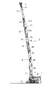
図1は本発明のブームを適用する作業機械の一実施の形態を示す側面図である。この作業機械は自走式車両1と作業具2を取付けた多関節ブーム3とからなる。自走式車両1はクローラ式(ホイール式でもよい)走行体4上に旋回体5を設置し、旋回体5には油圧パワーユニット6や運転室7等を搭載すると共に、前記多関節ブーム3を取付けてなる。この例においては、作業具2が建造物の破砕、鉄筋切断等を行なうための開閉式破砕具である場合について示す。
FIG. 1 is a side view showing an embodiment of a working machine to which a boom of the present invention is applied. This work machine includes a self-propelled
多関節ブーム3は、下ブーム8と中ブーム9と上ブーム10とからなる。この実施の形態の下ブーム8は、4本の分割ブーム8a〜8dを分割可能に結合した継ぎ足し式のブームでなる。また、この実施の形態の上ブーム10は、2本の分割ブーム10a、10bを分割可能に結合した継ぎ足し式ブームでなる。また、解体対象の高さによって下ブーム8の分割ブーム8a〜8dにさらに分割ブームを継ぎ足しあるいは抜き取って下ブーム8を構成することもあり、分割ブーム10a、10b間にもさらに分割ブームを継ぎ足して上ブーム10を構成することもある。
The
11は多関節ブーム3を俯仰動させる油圧式ブームシリンダであり、このブームシリンダ11は旋回体5と下ブーム8の基端側分割ブーム8aとの間に設けられる。12は下ブーム8に対して中ブーム9以上の部分を回動させる油圧式ブームシリンダ(第1のブームシリンダ)であり、このブームシリンダ12は下ブーム8の先端側分割ブーム8dと中ブーム9との間に設けられる。13は中ブーム9に対して上ブーム10を回動させる油圧式ブームシリンダ(第2のブームシリンダ)であり、このブームシリンダ13は中ブーム9と上ブーム10の基端側分割ブーム10aとの間に設けられる。14は作業具2を回動させる油圧式作業具シリンダである。
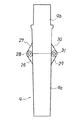
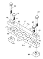
図2(A)は中ブーム9と分割ブーム8d、10bとの連結構造を示す側面図、図2(B)はその部分拡大図、図3は多関節ブーム3を起立させた状態で背面側となる方向から中ブーム9を見た図(背面図)である。図2(A)、(B)、図3に示すように、中ブーム9は、下半部9aと上半部9bとにより構成される。15は下ブーム8の先端側分割ブーム8dと下半部9aとを回動可能に連結するピン、16は上半部9bと上ブーム10の基端側分割ブーム10aとを回動可能に連結するピンである。下ブーム8の分割ブーム8dの前面(多関節ブーム3を起立させた状態における前面を意味する。以下同じ。)と中ブーム9の下半部9aの前面にそれぞれブラケット17、18を設け、これらのブラケット17、18に両端をピン19、20により連結してブームシリンダ12を取付ける。また、上半部9bの前面と上ブーム10の分割ブーム10aにそれぞれブラケット22、23を設け、これらのブラケット22、23に両端をピン24、25により連結してブームシリンダ13を取付ける。
2A is a side view showing a connection structure between the middle boom 9 and the divided
図2(B)、図3に示すように、中ブームの下半部9aと上半部9bの一方の側面には互いに重なり合うブラケット26、27を2枚ずつ設けて両ブラケット26、27のピン孔に挿着するピン28により下半部9aと上半部9bとを結合する。他方の側面にもそれぞれ同様の構成のブラケット29、30を設けてこれらのブラケット29、30のピン孔に挿着するピン31により下半部9aと上半部9bとを着脱可能に結合する。なお、これらのブラケット29、30やピン31の代わりに例えば結合部材を下半部9aと上半部9bにボルト等により着脱可能に取付け、この結合部材やボルト等により下半部9aと上半部9bの他方の側面同士を結合、分離可能とした構成にしてもよい。
As shown in FIGS. 2B and 3, two
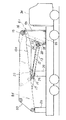
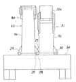
このブーム3は、中ブーム9の側面側のブラケット29、30のピン孔に挿着するピン31を抜くことにより、下半部9aに対して上半部9bがピン28を中心として回動可能となる。このため、図4の側面図、図5の平面図、図6の正面図に輸送状態について示すように、中ブーム9を分解せず、中ブーム9に下ブーム8の分割ブーム8d、上ブーム10の分割ブーム10aを結合したままで輸送することができる。すなわち、下半部9aに下ブーム8の分割ブーム8dに結合し、かつブームシリンダ12を付けたままで第1のブーム構成体60を構成し、また、上半部9bに上ブーム10の分割ブーム10aとを結合し、かつブームシリンダ13を付けたままで第2のブーム構成体61を構成し、ピン28中心に下半部9aに対して上半部9bを回動させて各一方の側面が互いに対面するように折り畳み、第1のブーム構成体60と第2のブーム構成体61をトラック34の荷台上に左右に並べて搭載することができる。図示のように、この例では輸送に用いるトラック34は、図11に示した旋回可能な接続装置75cを持つトレーラトラックではないトラックである。
In the
このブームの輸送の際の搭載作業は一例として次のように行なわれる。まずブーム3を倒し、上ブーム10の分割ブーム10bを作業具2と共に分割ブーム10aから外す。なおこのとき、作業具2を作動させるための油圧ホースや、作業具2を回動するための作業具シリンダ14に接続される油圧ホースは、中ブーム9と上ブーム10との間の継手部分で分離する。
As an example, the mounting operation for transporting the boom is performed as follows. First, the
次に、下半部9a、上半部9bの一方の側面のブラケット29、30のピン孔に挿着していたピン31を外す。そして上半部9b(または分割ブーム10a)に設けられている吊輪にクレーンの巻上ロープのフック(いずれも図示せず)を掛け、クレーン操作により上半部9bを分割ブーム10aと共にピン28を中心に回動させ、中ブーム9の下半部9aと上半部9bとを一側面部が対面するように折り畳むと同時に、分割ブーム8dと分割ブーム10aとを並べる。
Next, the
次にブームシリンダ12、13を同時に収縮させて下半部9aと上半部9bの合わせ面を下向きにする。次に下ブーム8の分割ブーム8dから分割ブーム8cを外すと同時に、これらの分割ブーム8c、8d間に設けられていた油圧ホースの継手も分離する。そしてこのように分割ブーム8d、10a、下半部9a、上半部9bを結合したままの状態で図4〜図6に示すようにトラック34の荷台上にクレーンにより載せる。すなわち、トラック34に予めセットされている分割ブーム8d、10a用の台35、36上に分割ブーム8d、10aの端部を載せると共に、下半部9a、上半部9bの合わせ面をトラック34の荷台上に載せる。また、トレーラ34上の分割ブーム8d、10aや下半部9a、上半部9bはトレーラ34や台35、36にチェーンあるいは適宜の留め部材により固定する。保管時にも同様の姿勢で保管することができる。
Next, the
この輸送、保管における上記状態から現場でブーム3を組み立てる場合は、前記手順と逆の手順で組み立てることができる。すなわち、トラック34上に中ブーム9、分割ブーム8d、10aおよびブームシリンダ12、13を搭載した状態からクレーンによりこれを組立台上に下ろし、自走式車両1の自走、旋回およびブームシリンダ11の伸縮により、トレーラ34上の分割ブーム8dの基端側に分割ブーム8cの先端を合わせ、ピンまたはボルトによりこれらの分割ブーム8c、8dを結合する。また、同時にこれらの分割ブーム8c、8dに添設されている油圧ホースの継手同士を接続する。そしてブームシリンダ11の伸長により、分割ブーム10bを付けていない状態のブームを持ち上げ、ブームシリンダ12、13を同時に最伸長状態にまで伸長させる。
When assembling the
次に上半部9bまたは分割ブーム10aをクレーンの巻上ロープに接続し、クレーン操作により、分割ブーム10aと共に上半部9bをピン28中心に回動させ、下半部9aと上半部9bの合わせ面を合わせて分割ブーム10aを本来の向きにした後、ブラケット29、30のピン孔にピン31を挿着して上半部9bのピン28の反対側の側面部を下半部9aの対応する側面部に結合する。次に分割ブーム10aに、作業具2を取付けた分割ブーム10bを分割ブーム10aに結合する。
Next, the
また、分割ブーム8a〜8d間あるいは10a、10bに別の継ぎ足し用の分割ブームが設けられる場合には、さらにその継ぎ足し用の分割ブームの分解、組立作業が加わることになる。
Further, when another split boom for addition is provided between the
このように、この実施の形態においては、輸送や保管の当って、中ブーム9の下半部9aと上半部9bとを分解せず、かつ下ブーム8の分割ブーム8dと上ブーム10の分割ブーム10aとを中ブーム9に対して分解せず、さらに中ブーム9と下ブーム8の分割ブーム8dや、上ブーム10の分割ブーム10aを連結しているブームシリンダ12、13を取付けたままで輸送、保管することが可能となる。なお、前記輸送、保管時に、ブームシリンダ12、13が最収縮状態またはこれに近い収縮状態とすることにより、ブームシリンダ12、13のピストンロッドの防錆、防傷効果を得ることができる。
Thus, in this embodiment, the
また、この輸送、保管における上記状態から現場でブームを組み立てる場合は、前記輸送姿勢から、下半部9aに対して上半部9bの回動させることで下半部9aに対する上半部9bの合わせ面を合わせてピン31により結合して組み立てることが可能であり、従来の中ブーム9を分割する場合のように、中ブーム9の下半部9aと上半部9bとを分解したり、その分解状態から両者の結合部の位置合わせをして結合する作業が不要となり、その作業に要する手間、労力、時間が削減され、分解、組立が容易となる。
Also, when assembling the boom on site from the above state in transportation and storage, the
また、輸送、保管の状態においては、図4〜図6に示したように、中ブーム9を一側面部を中心に折り畳むことにより、下ブーム8の分割ブーム8dと上ブーム10の分割ブーム10aとが中ブーム9に対して連結された状態で、下ブーム8の分割ブーム8dと上ブーム10の分割ブーム10bとを並べて輸送、保管することができるので、従来のように、分割ブーム8a、10bをそれぞれ下半部9a、上半部9bに結合したままで別々のトレーラトラックで輸送する場合に比較してトラック34の台数を削減したり、保管スペースを狭くすることができる。また、図11に示したように、下ブームの先端側分割ブーム70、中ブーム71、上ブームの基端側分割ブーム72を長手方向に並べてトラック75に搭載する場合に比較し、トレーラトラックではない比較的短いトラック34を用いて輸送することができ、輸送が容易になると共に、輸送費が削減でき、経済化が達成できる。
Further, in the state of transportation and storage, as shown in FIGS. 4 to 6, the middle boom 9 is folded around the one side surface portion, thereby dividing the divided
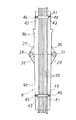
次に本発明の他の実施の形態を図7〜図9により説明する。図7に示すように、中ブーム9の下半部9a、上半部9bの背面には、それぞれ、中ブーム9から上ブーム10にわたって添設される油圧ホース40を固定するためのクランプ41が取付けられる。これらの油圧ホース40は作業具2を開閉させる油圧シリンダや、作業具2を回動させる作業具シリンダ14に接続されるものである。
Next, another embodiment of the present invention will be described with reference to FIGS. As shown in FIG. 7, clamps 41 for fixing a
図8に示すように、クランプ41は、下クランプ41aと上クランプ41bとからなり、下クランプ41aと上クランプ41bの対向面には、油圧ホース40を収容して固定する半円形の凹部42が設けられる。43は下クランプ41aに上クランプ41bを常時固定しておくためのボルトであり、このボルト43は上クランプ41bに設けたボルト挿通孔44に挿通し、下クランプ41aに設けたねじ孔45に螺合し締結することにより、下クランプ41aと上クランプ41bとを互いに固定する。46はこのクランプ41を下半部9a、上半部9bに固定するボルトである。このボルト46は下クランプ41aと上クランプ41bの両端部に設けたボルト挿通孔47、48に挿通し、下半部9aおよび上半部9bに溶接されたナット49に螺合することにより、下半部9a、上半部9bにクランプ41が下半部9a、9bに着脱可能に取付けられる。
As shown in FIG. 8, the
この実施の形態においては、輸送、保管に当たり、クランプ41の下半部9a、上半部9bへの固定用ボルト46を外してクランプ41、41を下半部9a、9bに対してフリーとする。そして図9に示すように、輸送、保管の状態、すなわち下半部9aに対して上半部9bを折り畳んだ状態では、油圧ホース40はクランプ41により保持されたままで曲がった状態となる。
In this embodiment, for transportation and storage, the fixing
この実施の形態のように、油圧ホース40を固定するクランプ41を中ブーム9に対して着脱可能とし、輸送、保管において、クランプ41を中ブーム9から外し、中ブーム9を折り畳み、油圧ホース40を上下ブーム8、10間で接続したまま輸送、保管することができる構成とすれば、油圧ホース40の中ブーム9の部分における分解、組立作業も不要となり、輸送、保管と現場作業に際してのブームの分解、組立作業に要する作業の手間、労力がさらに削減できる。
As in this embodiment, the
図10は本発明の参考例を示す作業機械であり、中ブーム9と上ブーム50との間に別の中ブーム51を挿入した例である。この例の中ブーム51は分割ブーム51a、51bを継ぎ足したもので、分割ブーム51aと中ブーム9の上半部9bとの間にブームシリンダ52が取付けられ、分割ブーム51bと上ブーム10との間に別のブームシリンダ53が取付けられる。この参考例においては、図4〜図6で示した分割ブーム10aの代わりに中ブーム51の分割ブーム51aが下ブーム8の分割ブーム8dや中ブーム9の下半部9a、上半部9b、およびブームシリンダ12、52と連結したままで、かつ中ブーム9の下半部9a、上半部9bを折り畳んだ状態で輸送、保管されることになる。
FIG. 10 is a working machine showing a reference example of the present invention, in which another
本発明のブームは、上ブーム10の少なくとも一部を伸縮式としたものにも適用できる。また、作業具2としては、図示のような鋏状の破砕具のみでなく、チゼルを振動させて破砕するブレーカや、散水具あるいはこれらの作業具を複合して備えたもの等、高所における作業に用いられる作業具を有する他の作業機械に適用可能である。
The boom of the present invention can also be applied to a type in which at least a part of the
1:自走式車両、2:作業具、3:ブーム、4:走行体、5:旋回体、6:油圧パワーユニット、7:運転室、8:下ブーム、8a〜8d:分割ブーム、9:中ブーム、9a:下半部、9b:上半部、10:上ブーム、10a、10b:分割ブーム、11:ブームシリンダ、12:第1のブームシリンダ、13:第2のブームシリンダ、14:作業具シリンダ、15、16:ピン、17、18:ブラケット、20、21:ピン、22、23:ブラケット、24、25:ピン、26、27:ブラケット、28:ピン、29、30:ブラケット、31:ピン、34:トラック、35、36:台、40:油圧ホース、41:クランプ、41a:下クランプ、41b:上クランプ、42:凹部、43:ボルト、44:ボルト挿通孔、45:ねじ孔、46:ボルト、47、48:ボルト挿通孔、49:ナット、50:上ブーム、51:中ブーム、51a、51b:分割ブーム、52、53:ブームシリンダ、60:第1のブーム構成体、61:第2のブーム構成体 1: Self-propelled vehicle, 2: Working tool, 3: Boom, 4: Traveling body, 5: Revolving body, 6: Hydraulic power unit, 7: Driver's cab, 8: Lower boom, 8a-8d: Split boom, 9: Middle boom, 9a: lower half, 9b: upper half, 10: upper boom, 10a, 10b: split boom, 11: boom cylinder, 12: first boom cylinder, 13: second boom cylinder, 14: Work tool cylinder, 15, 16: Pin, 17, 18: Bracket, 20, 21: Pin, 22, 23: Bracket, 24, 25: Pin, 26, 27: Bracket, 28: Pin, 29, 30: Bracket, 31: Pin, 34: Track, 35, 36: Base, 40: Hydraulic hose, 41: Clamp, 41a: Lower clamp, 41b: Upper clamp, 42: Recess, 43: Bolt, 44: Bolt insertion hole, 45: Screw Hole, 6: bolt, 47, 48: bolt insertion hole, 49: nut, 50: upper boom, 51: middle boom, 51a, 51b: split boom, 52, 53: boom cylinder, 60: first boom component, 61 : Second boom component
Claims (2)
前記多関節ブームは、分割可能な継ぎ足し式ブームでなる下ブームと、分割可能な継ぎ足し式ブームでなる上ブームと、前記下ブームと前記上ブームとを連結する中ブームとを備え、各関節部に設けるブームシリンダにより回動可能に連結して構成すると共に、上ブームの先端に作業具を取付けてなる作業機械において、
前記中ブームを下半部と上半部とにより構成し、前記多関節ブームの起立状態における前記下半部の前面側と前記分割可能な継ぎ足し式下ブームのうち前記下半部に隣接する下ブームの前面側とを第1のブームシリンダで連結すると共に、
前記多関節ブームの起立状態における前記上半部の前面側と前記分割可能な継ぎ足し式上ブームのうち前記上半部に隣接する上ブームの前面側とを第2のブームシリンダで連結し、
前記下半部と前記上半部の一方の側面側にそれぞれブラケットを設けてそのブラケット同士をピンにより結合し、他方の側面側同士を結合部材により着脱可能に結合し、
前記他方の側面側の結合部材による結合を解くことにより、前記下半部に対して前記上半部が前記ピン中心に回動可能となるように構成し、
前記下半部と前記上半部とを前記一方の側面側のピンを中心に回動させて折畳んだ際に前記一方の側面側を互いに対面させると共に、前記第1および第2のブームシリンダを短縮させた際に前記下半部と前記上半部とが結合した状態で、それぞれの合わせ面が下側を向くように前記下半部と前記上半部の合わせ面を形成したことを特徴とする作業機械のブーム。 An articulated boom is attached to the swing body of a self-propelled vehicle so that it can be raised and lowered by a boom cylinder.
The articulated boom comprises a lower boom made of divisible topped Boom, a boom top made of divisible topped Boom, and a boom in which connecting the on the boom and the lower boom, the joint In a working machine in which a work cylinder is configured to be pivotally connected by a boom cylinder provided in the upper boom, and a work tool is attached to the tip of the upper boom.
It said in boom constituted by a lower half and an upper half portion, the lower adjacent the said lower half portion of the articulated boom wherein the splittable topped formula under the boom and the front side of the lower half portion in the upright position of together when connecting the front face side of the boom in the first boom cylinder,
Wherein a front side of the boom top adjacent to the upper half of the splittable topped formula on the boom and the front side of the upper half in the upright position of the articulated boom connected by a second boom cylinder,
Brackets are provided on one side of the lower half and the upper half, respectively, and the brackets are coupled by pins, and the other side is detachably coupled by a coupling member,
The upper half is configured to be rotatable about the pin with respect to the lower half by releasing the coupling by the coupling member on the other side surface,
When the lower half and the upper half are folded around a pin on the one side, the one side faces each other and the first and second boom cylinders When the lower half and the upper half are joined together, the mating surfaces of the lower half and the upper half are formed so that each mating surface faces downward. A boom for working machines.
前記上半部と下半部とに分割した中ブームから上ブームに添設する油圧ホースを備え、前記油圧ホースを前記中ブームの背面に固定するクランプを、前記中ブームに対して着脱可能に取付けたことを特徴とする作業機械のブーム。 In the boom of the working machine according to claim 1,
A hydraulic hose attached to the upper boom from the middle boom divided into the upper half and the lower half is provided, and a clamp for fixing the hydraulic hose to the back of the middle boom is detachable from the middle boom A boom of a work machine characterized by being installed.
Priority Applications (1)
| Application Number | Priority Date | Filing Date | Title |
|---|---|---|---|
| JP2007120300A JP4790657B2 (en) | 2007-04-27 | 2007-04-27 | Work machine boom |
Applications Claiming Priority (1)
| Application Number | Priority Date | Filing Date | Title |
|---|---|---|---|
| JP2007120300A JP4790657B2 (en) | 2007-04-27 | 2007-04-27 | Work machine boom |
Publications (2)
| Publication Number | Publication Date |
|---|---|
| JP2008274662A JP2008274662A (en) | 2008-11-13 |
| JP4790657B2 true JP4790657B2 (en) | 2011-10-12 |
Family
ID=40052953
Family Applications (1)
| Application Number | Title | Priority Date | Filing Date |
|---|---|---|---|
| JP2007120300A Expired - Fee Related JP4790657B2 (en) | 2007-04-27 | 2007-04-27 | Work machine boom |
Country Status (1)
| Country | Link |
|---|---|
| JP (1) | JP4790657B2 (en) |
Cited By (1)
| Publication number | Priority date | Publication date | Assignee | Title |
|---|---|---|---|---|
| US11885106B2 (en) | 2019-06-04 | 2024-01-30 | Kubota Corporation | Working machine |
Families Citing this family (4)
| Publication number | Priority date | Publication date | Assignee | Title |
|---|---|---|---|---|
| JP5923028B2 (en) * | 2012-11-19 | 2016-05-24 | 日立建機株式会社 | Work front of work equipment and its transportation method |
| JP6983741B2 (en) * | 2018-09-27 | 2021-12-17 | 日立建機株式会社 | Work machine |
| JP6971212B2 (en) * | 2018-09-27 | 2021-11-24 | 日立建機株式会社 | Work machine |
| JP7088801B2 (en) * | 2018-09-28 | 2022-06-21 | 日立建機株式会社 | Work machine |
Family Cites Families (4)
| Publication number | Priority date | Publication date | Assignee | Title |
|---|---|---|---|---|
| JPH11200408A (en) * | 1998-01-13 | 1999-07-27 | Yutani Heavy Ind Ltd | Hydraulic hose laying structure of construction machine |
| JP2000273904A (en) * | 1999-03-23 | 2000-10-03 | Kubota Corp | Piping structure of rotating work machine |
| JP4492077B2 (en) * | 2003-09-26 | 2010-06-30 | コベルコ建機株式会社 | Work machine boom and its assembly / disassembly method |
| JP2006214160A (en) * | 2005-02-03 | 2006-08-17 | Sumitomo (Shi) Construction Machinery Manufacturing Co Ltd | Wheel-mounted construction machinery |
-
2007
- 2007-04-27 JP JP2007120300A patent/JP4790657B2/en not_active Expired - Fee Related
Cited By (1)
| Publication number | Priority date | Publication date | Assignee | Title |
|---|---|---|---|---|
| US11885106B2 (en) | 2019-06-04 | 2024-01-30 | Kubota Corporation | Working machine |
Also Published As
| Publication number | Publication date |
|---|---|
| JP2008274662A (en) | 2008-11-13 |
Similar Documents
| Publication | Publication Date | Title |
|---|---|---|
| US5484069A (en) | Process for self-disassembling a crawler crane | |
| JP4790657B2 (en) | Work machine boom | |
| US20070241074A9 (en) | Pipelayer crane excavator apparatus and methods | |
| JP5513820B2 (en) | Trunnion transport system and crane using the same | |
| US7287949B2 (en) | Mobile apparatus for earth moving and other operations such as lifting and displacing of loads | |
| JP3699266B2 (en) | Attitude holding device for working device used for front device for construction machine | |
| US7686174B2 (en) | Vehicle crane with a telescopic boom, as well as process for assembling and disassembling the anchor supports of the telescopic boom | |
| JP5129416B2 (en) | Crawler crane with left and right crawler assemblies identical to each other | |
| JP5302928B2 (en) | Work machine front attachment | |
| JP4803606B2 (en) | Transport method for work machine boom | |
| JP4835209B2 (en) | Crane winch removal method and upper swing body | |
| US4609204A (en) | Extension for outrigger beam | |
| US7926206B1 (en) | Tractor with detachable implement handling apparatus | |
| JP5923028B2 (en) | Work front of work equipment and its transportation method | |
| CN108442442A (en) | It digs pit, upright bar, be lifted all-in-one machine | |
| WO2020066120A1 (en) | Work machine | |
| JP6622514B2 (en) | Installation method of construction machine and car body weight | |
| JP5270616B2 (en) | Construction machine earth removal equipment | |
| RU65832U1 (en) | LOADING AND UNLOADING MACHINE | |
| JP5466672B2 (en) | Front device for construction machine and its mounting table | |
| JP4875974B2 (en) | Jacking machine for construction machinery | |
| JP3153766B2 (en) | Long object transport trolley | |
| AU2007201043B2 (en) | Pipelayer crane excavator apparatus and methods | |
| JP2001335283A (en) | Assembly/disassembly type portal lifter | |
| AU2005100323A4 (en) | A workbox |
Legal Events
| Date | Code | Title | Description |
|---|---|---|---|
| A621 | Written request for application examination |
Free format text: JAPANESE INTERMEDIATE CODE: A621 Effective date: 20090501 |
|
| A977 | Report on retrieval |
Free format text: JAPANESE INTERMEDIATE CODE: A971007 Effective date: 20101122 |
|
| A131 | Notification of reasons for refusal |
Free format text: JAPANESE INTERMEDIATE CODE: A131 Effective date: 20101208 |
|
| A521 | Request for written amendment filed |
Free format text: JAPANESE INTERMEDIATE CODE: A523 Effective date: 20110202 |
|
| TRDD | Decision of grant or rejection written | ||
| A01 | Written decision to grant a patent or to grant a registration (utility model) |
Free format text: JAPANESE INTERMEDIATE CODE: A01 Effective date: 20110719 |
|
| A01 | Written decision to grant a patent or to grant a registration (utility model) |
Free format text: JAPANESE INTERMEDIATE CODE: A01 |
|
| A61 | First payment of annual fees (during grant procedure) |
Free format text: JAPANESE INTERMEDIATE CODE: A61 Effective date: 20110720 |
|
| FPAY | Renewal fee payment (event date is renewal date of database) |
Free format text: PAYMENT UNTIL: 20140729 Year of fee payment: 3 |
|
| R150 | Certificate of patent or registration of utility model |
Ref document number: 4790657 Country of ref document: JP Free format text: JAPANESE INTERMEDIATE CODE: R150 Free format text: JAPANESE INTERMEDIATE CODE: R150 |
|
| LAPS | Cancellation because of no payment of annual fees |