JP4786852B2 - Improved structure for constructing building components - Google Patents
Improved structure for constructing building components Download PDFInfo
- Publication number
- JP4786852B2 JP4786852B2 JP2001561866A JP2001561866A JP4786852B2 JP 4786852 B2 JP4786852 B2 JP 4786852B2 JP 2001561866 A JP2001561866 A JP 2001561866A JP 2001561866 A JP2001561866 A JP 2001561866A JP 4786852 B2 JP4786852 B2 JP 4786852B2
- Authority
- JP
- Japan
- Prior art keywords
- sectional
- view
- shape
- cross
- plastic
- Prior art date
- Legal status (The legal status is an assumption and is not a legal conclusion. Google has not performed a legal analysis and makes no representation as to the accuracy of the status listed.)
- Expired - Fee Related
Links
Images


Classifications
-
- E—FIXED CONSTRUCTIONS
- E04—BUILDING
- E04C—STRUCTURAL ELEMENTS; BUILDING MATERIALS
- E04C3/00—Structural elongated elements designed for load-supporting
- E04C3/02—Joists; Girders, trusses, or trusslike structures, e.g. prefabricated; Lintels; Transoms; Braces
- E04C3/29—Joists; Girders, trusses, or trusslike structures, e.g. prefabricated; Lintels; Transoms; Braces built-up from parts of different material, i.e. composite structures
- E04C3/291—Joists; Girders, trusses, or trusslike structures, e.g. prefabricated; Lintels; Transoms; Braces built-up from parts of different material, i.e. composite structures with apertured web
-
- E—FIXED CONSTRUCTIONS
- E04—BUILDING
- E04C—STRUCTURAL ELEMENTS; BUILDING MATERIALS
- E04C2/00—Building elements of relatively thin form for the construction of parts of buildings, e.g. sheet materials, slabs, or panels
- E04C2/02—Building elements of relatively thin form for the construction of parts of buildings, e.g. sheet materials, slabs, or panels characterised by specified materials
- E04C2/10—Building elements of relatively thin form for the construction of parts of buildings, e.g. sheet materials, slabs, or panels characterised by specified materials of wood, fibres, chips, vegetable stems, or the like; of plastics; of foamed products
- E04C2/20—Building elements of relatively thin form for the construction of parts of buildings, e.g. sheet materials, slabs, or panels characterised by specified materials of wood, fibres, chips, vegetable stems, or the like; of plastics; of foamed products of plastics
- E04C2/22—Building elements of relatively thin form for the construction of parts of buildings, e.g. sheet materials, slabs, or panels characterised by specified materials of wood, fibres, chips, vegetable stems, or the like; of plastics; of foamed products of plastics reinforced
-
- E—FIXED CONSTRUCTIONS
- E04—BUILDING
- E04C—STRUCTURAL ELEMENTS; BUILDING MATERIALS
- E04C2/00—Building elements of relatively thin form for the construction of parts of buildings, e.g. sheet materials, slabs, or panels
- E04C2/02—Building elements of relatively thin form for the construction of parts of buildings, e.g. sheet materials, slabs, or panels characterised by specified materials
- E04C2/26—Building elements of relatively thin form for the construction of parts of buildings, e.g. sheet materials, slabs, or panels characterised by specified materials composed of materials covered by two or more of groups E04C2/04, E04C2/08, E04C2/10 or of materials covered by one of these groups with a material not specified in one of the groups
-
- E—FIXED CONSTRUCTIONS
- E04—BUILDING
- E04C—STRUCTURAL ELEMENTS; BUILDING MATERIALS
- E04C3/00—Structural elongated elements designed for load-supporting
- E04C3/38—Arched girders or portal frames
- E04C3/46—Arched girders or portal frames of materials not covered by groups E04C3/40 - E04C3/44; of a combination of two or more materials
Abstract
Description
【0001】
【発明の属する技術分野】
本発明は、土木及び建築で一般に使用される構造建築構成部品の製造産業に適用することができる。
【0002】
【従来の技術】
建築作業の実施に関する部品を形成するための、セメント、水、砂利及び混和剤の混合物からなるコンクリートの存在が知られている。マス・コンクリートや鉄筋コンクリートを使用することも可能で、それらは金属強化材を含むため、部品の機械的性質を向上させる。
【0003】
【発明が解決しようとする課題】
しかしながら、コンクリートにプラスチック等の材料が提供する可能性を提供することが望ましい。すなわち、この種の作業においてコンクリートにはない、極めて重要な特徴が提供されることが望ましい。
【0004】
出願人は、本発明の目的の構造が備えた改良の特性と水準としての構造に気づくに至った。
【0005】
【課題を解決するための手段】
本明細書は、建築構成部品を構成するための改良された構造に関する特許発明の出願に言及し、その基本的な関心は、金属とプラスチックの組み合わせを提供し、これらの材料を別々に用いた場合には得られない特性を備えた組立体を実現する建築部品の製造を可能にすることにある。
【0006】
建築構成部品を構成するための改良された構造は、詳細な説明を必要とする一連の利点を有する。
【0007】
金属とプラスチックの組み合わせは、それら別々の材料が個別に提供する機械的特徴より優れた特徴を有する複合材料を提供することを指摘することが重要である。すなわち、抵抗性、耐久性、軽量性、色彩、共振すなわち最低振動、きめ、順応性、耐食性、低い伝導性、経済性、及び適用や使用の際の扱いやすさ、などが挙げられる。
【0008】
これら全ての特徴は、本発明の重要な基本要素を統合するものである。
【0009】
上記目的を達成するため、本発明は、外側にプラスチックキャスティングを配置した内部金属構造体を提供する。
【0010】
提案される構造は、一方の材料の限界を、他方が提供する利点によって補償することを可能にし、両方の材料の共益関係を提供する本体を構成する。
【0011】
組み合わせを形成するために使用されるプラスチックは、各特定状況の要件により異なるものとされる。また、外側材料の内部に配置される構造体を構成する多くの金属構成材がある。
【0012】
更に、金属強化ラミネートあるいはプレートが、ボルト継手に設けられ、ボルト継手の持つ欠点を防ぐ。
【0013】
鋳型を用いることにより、プラスチック材料のキャスティングが実現される。また、プラスチックキャスティングに覆われる金属構造体には、現在用いられている製法のうちのいずれかが採用される。
【0014】
部品の寸法及び形状は、実用的な取り扱い易さ、抵抗性、重量及び経済性に関する基準によって決定される。
【0015】
提案される本発明は、一般の建築及び架設に適用される、どのような種類の部品の製造にも用いることができる。
【0016】
【発明の実施の形態】
以下、図面を参照して本発明の実施の形態について説明する。
建築構成部品を構成するための改良された構造は、2種類の材料、すなわち、プラスチックと金属の組み合わせから構成される。
【0017】
使用されるプラスチックは、各事例について決定される種類によって、異なった特性を有し、包装材(2)、(12)、(22)、(32)、(42)、(52)、(62)、(72)、(82)、(92)、(102)、(112)という総称を有する。異なった種類のプラスチック樹脂として、フェノプラスト、ポリカーボネート、ABS、ポリエチレン樹脂のような、サーモ及びデユラプラスチックが挙げられる。
【0018】
一方、包含される金属材(3)、(13)、(23)、(33)、(43)、(53)、(63)、(73)、(83)、(93)、(103)、(113)は、選択される適用例に従って、いかなる形状をも有し、その構造は、抵抗値2、800 Kg/cm2 を有するG−40波形鋼、抵抗値4、200 Kg/cm2 を有するG−60波形鋼、ロッド、電気溶接されたメッシュ、強化材、フレームあるいはシヤー、亜鉛及びアルミプレートあるいは鋼トラス、ワイヤー及びケーブルから得ることができる。
【0019】
組み合わせは、プラスチックキャスティング(2)、(12)、(22)、(32)、(42)、(52)、(62)、(72)、(82)、(92)、(102)、(112)の内部に、金属構造体(3)、(13)、(23)、(33)、(43)、(53)、(63)、(73)、(83)、(93)、(103)、(113)を導入することにより製造され、各構成材が他方の材料に欠ける点を補うような本体を得る。
【0020】
同様に、ボルト継手において発生する応力やずれの結果として生じる、外側プラスチックキャスティング(2)、(12)、(22)、(32)、(42)、(52)、(62)、(72)、(82)、(92)、(102)、(112)の浅割れやヒワレという問題を防止するための強化材として作用する金属ラミネートあるいはプレート(4)及び(4´)、(84)、(114)及び(114´)が存在する。
【0021】
最終形状に到達することを目的として、プラスチック材料(2)、(12)、(22)、(32)、(42)、(52)、(62)、(72)、(82)、(92)、(102)、(112)のキャスティングを可能にする鋳型が作成され、内部金属構造体(3)、(13)、(23)、(33)、(43)、(53)、(63)、(73)、(83)、(93)、(103)、(113)を包装する構成材は、同目的のために、可能なあらゆる方法を用いることができる。
【0022】
トランスファー成形あるいは生硬化による注入、押出し、直接キャスティングによるキャスティングのような製法を利用することが、合理的である。
【0023】
部品や構成材のジョイントあるいは延長部に、所定の抵抗性と固定性を可能にする、プレート及びボルト、アセンブリ、抗プラスチック接着剤、あるいはこれらの組み合わせを利用した固定手段を使用することができる。
【0024】
提案される複合材は、レール及びビーム(1)、パイプ(10)、ロッド(20)、チャネル(30)、アングル(40)、フラットバー(50)、Z部(60)、プロフィル(70)、ビーム(80)、波形プレート(90)、平坦プレート(100)、あるいはビームとカラムを接合するボルト(115)を備えた構造体(110)の製造に、用いることができる。
【0025】
当業者が、本発明の範囲とこれより派生する有利な点を理解するために、更なる説明は必要ないと考えられる。
【0026】
構成材の材料、形状、寸法及び配置は、本発明の本質を変えるものでない限り、変更可能である。
【0027】
本明細書に表記された用語は、常にもっとも広範で限定しない意味に解釈されなければならない。
【図面の簡単な説明】
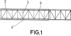
【図1】建築構成部品を構成するための改良された構造から作成されたレール及びビームの側立面図である。
【図2】プラスチック包装材、金属プレート、及び強化材が示されている第1図で検討されたレールあるいはビームの断面図である。
【図3】包装材と、内部の金属構成材とが分類されている、他の断面図であり、断面図Aはパイプに、断面図Bはロッドに、断面図Cはチャネルに、断面図Dはアングルに、断面図Eはフラットバーに、断面図FはZ部に、断面図Gはプロフィルに、断面図Hはビームに、それぞれ対応する。
【図4】断面図Iは波形プレートを表し、断面図Jは平坦プレートを表す、外側プラスチックと内側金属カバーを示す2つの断面図である。
【図5】ボルトにより接合されたビームとカラムにより形成された構造体の側立面図である。[0001]
BACKGROUND OF THE INVENTION
The present invention can be applied to the manufacturing industry of structural building components generally used in civil engineering and construction.
[0002]
[Prior art]
The existence of concrete consisting of a mixture of cement, water, gravel and admixture is known to form parts relating to the performance of building operations. It is also possible to use mass concrete or reinforced concrete, which includes metal reinforcements, thus improving the mechanical properties of the part.
[0003]
[Problems to be solved by the invention]
However, it is desirable to provide the potential for materials such as plastic to provide for concrete. That is, it is desirable to provide extremely important features not found in concrete in this type of work.
[0004]
Applicants have become aware of the improved characteristics and levels of structure that the object structure of the present invention has.
[0005]
[Means for Solving the Problems]
This specification refers to an application for a patented invention relating to an improved structure for constructing building components, the basic interest of which is to provide a combination of metal and plastic, using these materials separately. It is to enable the production of building parts that realize an assembly with characteristics that cannot be obtained in some cases.
[0006]
The improved structure for constructing building components has a series of advantages that require detailed description.
[0007]
It is important to point out that the combination of metal and plastic provides a composite material that has characteristics superior to the mechanical characteristics that these separate materials provide individually. That is, resistance, durability, lightness, color, resonance, that is, minimum vibration, texture, adaptability, corrosion resistance, low conductivity, economy, and ease of handling during application and use.
[0008]
All these features integrate important basic elements of the present invention.
[0009]
In order to achieve the above object, the present invention provides an internal metal structure having a plastic casting on the outside.
[0010]
The proposed structure makes it possible to compensate for the limitations of one material with the advantages provided by the other, and constitutes a body that provides a mutual benefit relationship for both materials.
[0011]
The plastic used to form the combination will vary depending on the requirements of each particular situation. There are also many metal components that make up the structure that is placed inside the outer material.
[0012]
In addition, a metal reinforced laminate or plate is provided on the bolt joint to prevent the disadvantages of the bolt joint.
[0013]
By using a mold, casting of a plastic material is realized. In addition, any of the currently used manufacturing methods is adopted for the metal structure covered with the plastic casting.
[0014]
The dimensions and shape of the parts are determined by criteria relating to practical ease of handling, resistance, weight and economy.
[0015]
The proposed invention can be used for the production of any kind of parts that are applied to general construction and erection.
[0016]
DETAILED DESCRIPTION OF THE INVENTION
Embodiments of the present invention will be described below with reference to the drawings.
The improved structure for constructing building components consists of a combination of two types of materials: plastic and metal.
[0017]
The plastic used has different characteristics depending on the type determined for each case, and the packaging materials (2), (12), (22), (32), (42), (52), (62) ), (72), (82), (92), (102), (112). Different types of plastic resins include thermo and deura plastics such as phenoplast, polycarbonate, ABS, polyethylene resin.
[0018]
On the other hand, the included metal materials (3), (13), (23), (33), (43), (53), (63), (73), (83), (93), (103) , (113), in accordance with applications to be selected, have any shape, the structure, G-40 waveform steel having a resistance value 2,800 Kg / cm 2, the resistance value 4,200 Kg / cm 2 Can be obtained from G-60 corrugated steel, rods, electro welded mesh, reinforcement, frames or shears, zinc and aluminum plates or steel trusses, wires and cables.
[0019]
The combinations are plastic casting (2), (12), (22), (32), (42), (52), (62), (72), (82), (92), (102), ( 112) inside the metal structures (3), (13), (23), (33), (43), (53), (63), (73), (83), (93), (93) 103) and (113) to obtain a main body that compensates for the lack of each component in the other material.
[0020]
Similarly, outer plastic castings (2), (12), (22), (32), (42), (52), (62), (72) resulting from the stresses and deviations that occur in the bolted joints. , (82), (92), (102), (112) a metal laminate or plate (4) and (4 ′), (84), which acts as a reinforcing material for preventing the problem of shallow cracks and cracks (114) and (114 ') exist.
[0021]
For the purpose of reaching the final shape, plastic materials (2), (12), (22), (32), (42), (52), (62), (72), (82), (92 ), (102), and (112) are cast to enable casting, and the internal metal structures (3), (13), (23), (33), (43), (53), (63) are created. ), (73), (83), (93), (103), and (113) can be formed using any possible method for the same purpose.
[0022]
It is reasonable to use a production method such as casting by transfer molding or bio-curing, extrusion, or direct casting.
[0023]
Fixing means using plates and bolts, assemblies, anti-plastic adhesives, or combinations thereof that allow for a predetermined resistance and fixability can be used at joints or extensions of parts and components.
[0024]
The proposed composites are rail and beam (1), pipe (10), rod (20), channel (30), angle (40), flat bar (50), Z section (60), profile (70). , A beam (80), a corrugated plate (90), a flat plate (100), or a structure (110) with a bolt (115) joining the beam and the column.
[0025]
In order for those skilled in the art to understand the scope of the invention and the advantages derived therefrom, further explanation is deemed unnecessary.
[0026]
The material, shape, dimensions and arrangement of the components can be changed unless they change the essence of the present invention.
[0027]
Terms appearing herein should always be interpreted in the broadest and non-limiting sense.
[Brief description of the drawings]
FIG. 1 is a side elevation view of a rail and beam made from an improved structure for constructing a building component.
FIG. 2 is a cross-sectional view of the rail or beam discussed in FIG. 1 showing plastic wrapping, metal plates, and reinforcement.
FIG. 3 is another cross-sectional view in which a packaging material and an internal metal component are classified, wherein cross-sectional view A is a pipe, cross-sectional view B is a rod, cross-sectional view C is a channel, and a cross-sectional view. D represents an angle, sectional view E corresponds to a flat bar, sectional view F corresponds to a Z portion, sectional view G corresponds to a profile, and sectional view H corresponds to a beam.
FIG. 4 is a two cross-sectional view showing an outer plastic and an inner metal cover, where cross-section I represents a corrugated plate and cross-section J represents a flat plate.
FIG. 5 is a side elevation view of a structure formed by a beam and a column joined by bolts.
Claims (1)
ボルト継手における強化のための金属ラミネートあるいはメッシュ(4)及び(4´)、(84)、(114)及び(114´)を含む均一体の内部金属構造体(3)、(13)、(23)、(33)、(43)、(53)、(63)、(73)、(83)、(93)、(103)、(113)と
からなるプラスチックと金属の組み合わせ体から構成され、
前記組み合わせ体は、プラスチック包装キャスティングの内部へ内部金属構造体が導入されることによって形成されものであり、
前記組み合わせ体は、基本単位材として、レール及びビーム(1)、パイプ(10)、ロッド(20)、チャネル(30)、アングル(40)、フラットバー(50)、Z部(60)、プロフィル(70)、ビーム(80)、波形プレート(90)、平坦プレート(100)を有し、
前記レール及びビーム(1)は、断面視において、単純なH字形状を有し、
前記パイプ(10)は、断面視において、単純な正方形形状を有し、
前記ロッド(20)は、断面視において、単純な正方形形状を有し、
前記チャネル(30)は、断面視において、単純な変形コ字形状を有し、
前記アングル(40)は、断面視において、単純なL字形状を有し、
前記フラットバー(50)は、断面視において、単純なI字形状を有し、
前記Z部(60)は、断面視において、単純な変形Z字形状を有し、
前記プロフィル(70)は、断面視において、単純な長方形形状を有し、
前記ビーム(80)は、断面視において、単純なT字形状を有し、
前記波形プレート(90)は、断面視において、単純な山形状が直線状に繰り返す形状を有し、
前記平坦プレート(100)は、断面視において、単純に直線状に伸びる形状を有し、
断面視において、前記プラスチック包装キャスティングの厚さ方向の幅は、前記内部金属構造体の厚さより大きい
ことを特徴とする、建築構成部品を構成するための改良された構造。Surrounding plastic packaging casting (2), (12), (22), (32), (42), (52), (62), (72), (82), (92), (102), (112),
Uniform internal metal structure (3), (13), (13), including metal laminate or mesh (4) and (4 '), (84), (114) and (114') for reinforcement in bolted joints 23), (33), (43), (53), (63), (73), (83), (93), (103), and (113). ,
The combination is formed by introducing an internal metal structure into the plastic packaging casting,
The combined body is composed of a rail and beam (1), a pipe (10), a rod (20), a channel (30), an angle (40), a flat bar (50), a Z portion (60), a profile as basic unit materials. (70), beam (80), corrugated plate (90), flat plate (100) ,
The rail and beam (1) have a simple H-shape in cross section,
The pipe (10) has a simple square shape in sectional view,
The rod (20) has a simple square shape in cross-sectional view,
The channel (30) has a simple U-shape in a sectional view,
The angle (40) has a simple L-shape in a sectional view,
The flat bar (50) has a simple I-shape in cross-sectional view,
The Z portion (60) has a simple deformation Z-shape in a cross-sectional view,
The profile (70) has a simple rectangular shape in cross-sectional view,
The beam (80) has a simple T-shape in cross-section,
The corrugated plate (90) has a shape in which a simple mountain shape repeats linearly in a sectional view,
The flat plate (100) has a shape that extends in a straight line in a sectional view,
An improved structure for constructing a building component, characterized in that, in cross-sectional view, the thickness of the plastic packaging casting in the thickness direction is greater than the thickness of the internal metal structure.
Applications Claiming Priority (4)
| Application Number | Priority Date | Filing Date | Title |
|---|---|---|---|
| ES200000423 | 2000-02-23 | ||
| ES200000423A ES2165309B1 (en) | 2000-02-23 | 2000-02-23 | IMPROVED PROVISION FOR THE CONFIGURATION OF CONSTRUCTION ELEMENTS. |
| ESP200000423 | 2000-02-23 | ||
| PCT/ES2000/000343 WO2001063067A1 (en) | 2000-02-23 | 2000-09-13 | Improved arrangement for configuring building elements |
Publications (2)
| Publication Number | Publication Date |
|---|---|
| JP2003524090A JP2003524090A (en) | 2003-08-12 |
| JP4786852B2 true JP4786852B2 (en) | 2011-10-05 |
Family
ID=8492426
Family Applications (1)
| Application Number | Title | Priority Date | Filing Date |
|---|---|---|---|
| JP2001561866A Expired - Fee Related JP4786852B2 (en) | 2000-02-23 | 2000-09-13 | Improved structure for constructing building components |
Country Status (7)
| Country | Link |
|---|---|
| US (1) | US6922969B1 (en) |
| EP (1) | EP1174559B1 (en) |
| JP (1) | JP4786852B2 (en) |
| AT (1) | ATE494432T1 (en) |
| DE (1) | DE60045478D1 (en) |
| ES (1) | ES2165309B1 (en) |
| WO (1) | WO2001063067A1 (en) |
Families Citing this family (28)
| Publication number | Priority date | Publication date | Assignee | Title |
|---|---|---|---|---|
| TW593850B (en) * | 2002-10-04 | 2004-06-21 | Lo Mao | Bending moment resistant structure with supporting member and method for the same |
| US20040074202A1 (en) * | 2002-10-22 | 2004-04-22 | Andrew Barmakian | Rod-reinforced cushion beam |
| US20050108980A1 (en) * | 2002-10-22 | 2005-05-26 | Andrew Barmakian | Rod-reinforced cushion beam |
| WO2004101909A1 (en) * | 2003-05-14 | 2004-11-25 | N.V. Bekaert S.A. | Pultruded composite profile reinforced by metal cords |
| US8065848B2 (en) * | 2007-09-18 | 2011-11-29 | Tac Technologies, Llc | Structural member |
| US20060107612A1 (en) * | 2004-10-01 | 2006-05-25 | Pelc Robert J | Anchoring device |
| US8323778B2 (en) * | 2005-01-13 | 2012-12-04 | Webb Alan C | Environmentally resilient corrugated building products and methods of manufacture |
| US20110036052A1 (en) * | 2009-08-14 | 2011-02-17 | Callahan Robert M | Reinforced girder |
| US20110036051A1 (en) * | 2009-08-14 | 2011-02-17 | Callahan Robert M | Reinforced girder |
| US20110036050A1 (en) * | 2009-08-14 | 2011-02-17 | Robert M Callahan | Reinforced girder |
| US20110225923A1 (en) * | 2010-03-17 | 2011-09-22 | Span-Lite, LLC | Joist Assemblies and Assembly Kits |
| GB201006408D0 (en) * | 2010-04-16 | 2010-06-02 | Keystone Lintels Ltd | A hybrid support structure |
| DE102011051510A1 (en) * | 2011-07-01 | 2013-01-03 | Michael Korff | Spacer for insulated support structures |
| WO2013015615A2 (en) * | 2011-07-28 | 2013-01-31 | 주식회사 한샘 | Hybrid wall panel structure for an assembly-type bath |
| AU2011232748B2 (en) * | 2011-10-05 | 2016-05-26 | Danpal Australia Pty Limited | Truss System |
| US20140090230A1 (en) * | 2012-04-12 | 2014-04-03 | William Culina | Method of making, transporting and installing soffit made by a machine that creates corrugated sheet metal soffit which soffit is coated with vinyl material which vinyl material coats one or both sides of the aluminum sheet metal prior to being fed through the machine that creates the corrugated soffit |
| US20140182241A1 (en) * | 2012-12-27 | 2014-07-03 | Jeong Moon Seo | Support beam with a steel core frame |
| US9803413B2 (en) | 2015-06-15 | 2017-10-31 | Endura Products, Inc. | Door assembly |
| DE202015104628U1 (en) * | 2015-09-01 | 2016-12-05 | Pfeifer Holding Gmbh & Co. Kg | Support beam for ceiling systems and ceiling system |
| US11286712B2 (en) | 2017-03-03 | 2022-03-29 | Endura Products, Llc | Door assembly |
| US10718151B2 (en) | 2017-03-03 | 2020-07-21 | Endura Products, Inc. | Door assembly |
| CA2997330C (en) | 2017-03-03 | 2021-02-02 | Endura Products, Inc. | Door assembly |
| US20190136532A1 (en) * | 2017-11-03 | 2019-05-09 | Axion Structural Innovations | Structural reinforced composite beam |
| RU2664520C1 (en) * | 2017-11-21 | 2018-08-20 | Михаил Борисович Жуков | T-beam |
| US11111715B2 (en) | 2018-04-25 | 2021-09-07 | Endura Products, Llc | Door assembly |
| US11203896B2 (en) | 2018-08-07 | 2021-12-21 | Endura Products, Llc | Entryway and weather strip for the same |
| USD934671S1 (en) | 2019-07-01 | 2021-11-02 | Endura Products, Llc | Door jamb |
| USD947663S1 (en) | 2019-07-01 | 2022-04-05 | Endura Products, Llc | Door mullion |
Citations (3)
| Publication number | Priority date | Publication date | Assignee | Title |
|---|---|---|---|---|
| JPS4956425A (en) * | 1972-10-02 | 1974-05-31 | ||
| JPS62170644A (en) * | 1986-01-22 | 1987-07-27 | 新村 正照 | Synthetic reinforcing structural material |
| JPH102029A (en) * | 1996-06-19 | 1998-01-06 | Ig Tech Res Inc | Steel house member |
Family Cites Families (17)
| Publication number | Priority date | Publication date | Assignee | Title |
|---|---|---|---|---|
| US2855021A (en) * | 1948-10-01 | 1958-10-07 | Bayer Ag | Process for producing plates, sheels and shaped elements |
| GB785283A (en) * | 1951-01-24 | 1957-10-23 | Hoechst Ag | Shaped carbon or graphite bodies of a high bending strength and high tensile strength |
| DE2024453A1 (en) * | 1970-05-20 | 1971-12-09 | Arbed S.A. Arbed - Feiten & Guilleaume Vereinigte Drahtwerke, 5000 Köln-Mülheim | High-strength, rod-shaped or flat component |
| US3810337A (en) * | 1970-10-28 | 1974-05-14 | S Pollard | An elongated stressed structural member |
| US3983205A (en) * | 1971-07-30 | 1976-09-28 | The British Petroleum Company Limited | Method of molding reinforced articles |
| US4081941A (en) * | 1976-10-18 | 1978-04-04 | Ceel-Co | Flexible protective cover sections, assemblies and form system |
| DE7901946U1 (en) * | 1979-01-25 | 1979-05-23 | Hamm, Wilfried, 4330 Muelheim | HANDRAIL ELEMENT FOR STAIRS |
| US4461134A (en) * | 1981-07-06 | 1984-07-24 | Lowe Colin F | Sheet metal beam |
| US4606167A (en) * | 1984-10-31 | 1986-08-19 | Parker Thorne | Fabricated round interior column and method of construction |
| DE3544544A1 (en) * | 1985-11-22 | 1987-05-27 | Rochus C Ruettnauer | Profile element of recycled plastic |
| EP0375601A1 (en) * | 1988-07-01 | 1990-06-27 | Hans Rudolf Weber | Baculiform construction element with a high rigidity, and use of same |
| DE4106036A1 (en) * | 1991-02-22 | 1992-08-27 | Groh Gmbh | ASSEMBLY AND SCAFFOLDING SYSTEM |
| US5379567A (en) * | 1993-02-12 | 1995-01-10 | Vahey; Michael | Structural member |
| US5471809A (en) * | 1994-01-31 | 1995-12-05 | Frankel; Arie | Reinforced plastic structural support member |
| JPH07317209A (en) * | 1994-05-24 | 1995-12-05 | Hiromu Kimura | Plastic structural material |
| US6505454B2 (en) * | 1996-06-22 | 2003-01-14 | Gerhard Dingler | Structural member |
| DE19818769C2 (en) * | 1998-04-27 | 2001-07-12 | Ingbuero Dr Ing Harald Schulz | Thermal insulation strip |
-
2000
- 2000-02-23 ES ES200000423A patent/ES2165309B1/en not_active Expired - Fee Related
- 2000-09-13 AT AT00962546T patent/ATE494432T1/en not_active IP Right Cessation
- 2000-09-13 WO PCT/ES2000/000343 patent/WO2001063067A1/en active Application Filing
- 2000-09-13 US US10/031,250 patent/US6922969B1/en not_active Expired - Fee Related
- 2000-09-13 JP JP2001561866A patent/JP4786852B2/en not_active Expired - Fee Related
- 2000-09-13 EP EP00962546A patent/EP1174559B1/en not_active Expired - Lifetime
- 2000-09-13 DE DE60045478T patent/DE60045478D1/en not_active Expired - Lifetime
Patent Citations (3)
| Publication number | Priority date | Publication date | Assignee | Title |
|---|---|---|---|---|
| JPS4956425A (en) * | 1972-10-02 | 1974-05-31 | ||
| JPS62170644A (en) * | 1986-01-22 | 1987-07-27 | 新村 正照 | Synthetic reinforcing structural material |
| JPH102029A (en) * | 1996-06-19 | 1998-01-06 | Ig Tech Res Inc | Steel house member |
Also Published As
| Publication number | Publication date |
|---|---|
| DE60045478D1 (en) | 2011-02-17 |
| JP2003524090A (en) | 2003-08-12 |
| ATE494432T1 (en) | 2011-01-15 |
| ES2165309A1 (en) | 2002-03-01 |
| EP1174559B1 (en) | 2011-01-05 |
| EP1174559A1 (en) | 2002-01-23 |
| WO2001063067A1 (en) | 2001-08-30 |
| US6922969B1 (en) | 2005-08-02 |
| ES2165309B1 (en) | 2003-05-16 |
Similar Documents
| Publication | Publication Date | Title |
|---|---|---|
| JP4786852B2 (en) | Improved structure for constructing building components | |
| US6799403B2 (en) | Deep-ribbed, load-bearing, prefabricated insulative panel and method for joining | |
| US8826626B2 (en) | Light-weight load-bearing structures | |
| CN107700667A (en) | A kind of precast floor slab and girder steel lower flange connecting node | |
| FI108306B (en) | thermos | |
| KR840002508A (en) | Acquisition method and structure of recessed cylindrical structure | |
| CN113175096A (en) | Prefabricated outer wall connected node of assembled steel construction | |
| JP2005226246A (en) | Joining structure for members | |
| KR100430317B1 (en) | Prefabricated Enclosed Steel Concrete Structures | |
| JPH0470438A (en) | Buckle restricting member for bracing | |
| FI20185632A1 (en) | Bearing wall structure and method for producing the same | |
| CN108487473A (en) | Prefabrication steel concrete compound shear wall with connect steel beam joint connection structure | |
| EP0164332B1 (en) | Constructional element having substantially constant wall thickness | |
| NZ550751A (en) | Fibre reinforced cement building panel with integral steel channel reinforcing | |
| KR102393700B1 (en) | the device fixing bar in detachable form and the detachable form structure using the same | |
| CN212773150U (en) | Multi-cavity light metal pipe concrete special-shaped column and connecting node with same | |
| JP2004137687A (en) | Fireproof composite member | |
| CN219118488U (en) | Buckle connecting piece and unilaterally detachable formwork superimposed shear wall | |
| KR102393701B1 (en) | the device fixing bar in detachable form and the detachable form structure using the same | |
| CN215106427U (en) | Hollow superimposed sheet of enhancement steel pipe truss prestressing force | |
| JP7403035B2 (en) | panel structure | |
| CN110605776B (en) | Die beam for building and preparation method | |
| KR200294571Y1 (en) | Hybrid girder using frp or frc | |
| US20180038107A1 (en) | Reinforced composite structure useful as studs, joists, rafters and other structural and non-structural building components | |
| JPH023864B2 (en) |
Legal Events
| Date | Code | Title | Description |
|---|---|---|---|
| A621 | Written request for application examination |
Free format text: JAPANESE INTERMEDIATE CODE: A621 Effective date: 20070810 |
|
| A131 | Notification of reasons for refusal |
Free format text: JAPANESE INTERMEDIATE CODE: A131 Effective date: 20100625 |
|
| A601 | Written request for extension of time |
Free format text: JAPANESE INTERMEDIATE CODE: A601 Effective date: 20100927 |
|
| A602 | Written permission of extension of time |
Free format text: JAPANESE INTERMEDIATE CODE: A602 Effective date: 20101004 |
|
| A521 | Request for written amendment filed |
Free format text: JAPANESE INTERMEDIATE CODE: A523 Effective date: 20101025 |
|
| A131 | Notification of reasons for refusal |
Free format text: JAPANESE INTERMEDIATE CODE: A131 Effective date: 20101119 |
|
| A601 | Written request for extension of time |
Free format text: JAPANESE INTERMEDIATE CODE: A601 Effective date: 20110221 |
|
| A602 | Written permission of extension of time |
Free format text: JAPANESE INTERMEDIATE CODE: A602 Effective date: 20110228 |
|
| A601 | Written request for extension of time |
Free format text: JAPANESE INTERMEDIATE CODE: A601 Effective date: 20110322 |
|
| A602 | Written permission of extension of time |
Free format text: JAPANESE INTERMEDIATE CODE: A602 Effective date: 20110329 |
|
| A601 | Written request for extension of time |
Free format text: JAPANESE INTERMEDIATE CODE: A601 Effective date: 20110419 |
|
| A602 | Written permission of extension of time |
Free format text: JAPANESE INTERMEDIATE CODE: A602 Effective date: 20110426 |
|
| A521 | Request for written amendment filed |
Free format text: JAPANESE INTERMEDIATE CODE: A523 Effective date: 20110512 |
|
| TRDD | Decision of grant or rejection written | ||
| A01 | Written decision to grant a patent or to grant a registration (utility model) |
Free format text: JAPANESE INTERMEDIATE CODE: A01 Effective date: 20110617 |
|
| A01 | Written decision to grant a patent or to grant a registration (utility model) |
Free format text: JAPANESE INTERMEDIATE CODE: A01 |
|
| A61 | First payment of annual fees (during grant procedure) |
Free format text: JAPANESE INTERMEDIATE CODE: A61 Effective date: 20110714 |
|
| R150 | Certificate of patent or registration of utility model |
Free format text: JAPANESE INTERMEDIATE CODE: R150 |
|
| FPAY | Renewal fee payment (event date is renewal date of database) |
Free format text: PAYMENT UNTIL: 20140722 Year of fee payment: 3 |
|
| R250 | Receipt of annual fees |
Free format text: JAPANESE INTERMEDIATE CODE: R250 |
|
| R250 | Receipt of annual fees |
Free format text: JAPANESE INTERMEDIATE CODE: R250 |
|
| LAPS | Cancellation because of no payment of annual fees |