JP4786536B2 - Disposable wearing items - Google Patents
Disposable wearing items Download PDFInfo
- Publication number
- JP4786536B2 JP4786536B2 JP2006525964A JP2006525964A JP4786536B2 JP 4786536 B2 JP4786536 B2 JP 4786536B2 JP 2006525964 A JP2006525964 A JP 2006525964A JP 2006525964 A JP2006525964 A JP 2006525964A JP 4786536 B2 JP4786536 B2 JP 4786536B2
- Authority
- JP
- Japan
- Prior art keywords
- panel
- chassis
- end portion
- tip
- distal end
- Prior art date
- Legal status (The legal status is an assumption and is not a legal conclusion. Google has not performed a legal analysis and makes no representation as to the accuracy of the status listed.)
- Expired - Fee Related
Links
Images


Classifications
-
- A—HUMAN NECESSITIES
- A61—MEDICAL OR VETERINARY SCIENCE; HYGIENE
- A61F—FILTERS IMPLANTABLE INTO BLOOD VESSELS; PROSTHESES; DEVICES PROVIDING PATENCY TO, OR PREVENTING COLLAPSING OF, TUBULAR STRUCTURES OF THE BODY, e.g. STENTS; ORTHOPAEDIC, NURSING OR CONTRACEPTIVE DEVICES; FOMENTATION; TREATMENT OR PROTECTION OF EYES OR EARS; BANDAGES, DRESSINGS OR ABSORBENT PADS; FIRST-AID KITS
- A61F13/00—Bandages or dressings; Absorbent pads
- A61F13/15—Absorbent pads, e.g. sanitary towels, swabs or tampons for external or internal application to the body; Supporting or fastening means therefor; Tampon applicators
- A61F13/53—Absorbent pads, e.g. sanitary towels, swabs or tampons for external or internal application to the body; Supporting or fastening means therefor; Tampon applicators characterised by the absorbing medium
- A61F13/534—Absorbent pads, e.g. sanitary towels, swabs or tampons for external or internal application to the body; Supporting or fastening means therefor; Tampon applicators characterised by the absorbing medium having an inhomogeneous composition through the thickness of the pad
- A61F13/535—Absorbent pads, e.g. sanitary towels, swabs or tampons for external or internal application to the body; Supporting or fastening means therefor; Tampon applicators characterised by the absorbing medium having an inhomogeneous composition through the thickness of the pad inhomogeneous in the plane of the pad, e.g. core absorbent layers being of different sizes
-
- A—HUMAN NECESSITIES
- A61—MEDICAL OR VETERINARY SCIENCE; HYGIENE
- A61F—FILTERS IMPLANTABLE INTO BLOOD VESSELS; PROSTHESES; DEVICES PROVIDING PATENCY TO, OR PREVENTING COLLAPSING OF, TUBULAR STRUCTURES OF THE BODY, e.g. STENTS; ORTHOPAEDIC, NURSING OR CONTRACEPTIVE DEVICES; FOMENTATION; TREATMENT OR PROTECTION OF EYES OR EARS; BANDAGES, DRESSINGS OR ABSORBENT PADS; FIRST-AID KITS
- A61F13/00—Bandages or dressings; Absorbent pads
- A61F13/15—Absorbent pads, e.g. sanitary towels, swabs or tampons for external or internal application to the body; Supporting or fastening means therefor; Tampon applicators
- A61F13/45—Absorbent pads, e.g. sanitary towels, swabs or tampons for external or internal application to the body; Supporting or fastening means therefor; Tampon applicators characterised by the shape
- A61F13/49—Absorbent articles specially adapted to be worn around the waist, e.g. diapers
- A61F13/495—Absorbent articles specially adapted to be worn around the waist, e.g. diapers with faecal cavity
-
- A—HUMAN NECESSITIES
- A61—MEDICAL OR VETERINARY SCIENCE; HYGIENE
- A61F—FILTERS IMPLANTABLE INTO BLOOD VESSELS; PROSTHESES; DEVICES PROVIDING PATENCY TO, OR PREVENTING COLLAPSING OF, TUBULAR STRUCTURES OF THE BODY, e.g. STENTS; ORTHOPAEDIC, NURSING OR CONTRACEPTIVE DEVICES; FOMENTATION; TREATMENT OR PROTECTION OF EYES OR EARS; BANDAGES, DRESSINGS OR ABSORBENT PADS; FIRST-AID KITS
- A61F13/00—Bandages or dressings; Absorbent pads
- A61F13/15—Absorbent pads, e.g. sanitary towels, swabs or tampons for external or internal application to the body; Supporting or fastening means therefor; Tampon applicators
- A61F13/53—Absorbent pads, e.g. sanitary towels, swabs or tampons for external or internal application to the body; Supporting or fastening means therefor; Tampon applicators characterised by the absorbing medium
- A61F13/534—Absorbent pads, e.g. sanitary towels, swabs or tampons for external or internal application to the body; Supporting or fastening means therefor; Tampon applicators characterised by the absorbing medium having an inhomogeneous composition through the thickness of the pad
Description
本発明は、排泄物を吸収、保持する使い捨て着用物品に関する。 The present invention relates to a disposable wearing article that absorbs and holds excrement.
前胴周り域および後胴周り域とそれら胴周り域の間に位置する股下域とを有し、肌当接側に位置する透液性表面シートと、肌非当接側に位置する不透液性裏面シートと、表裏面シートの間に介在して前後胴周り域間に延びる吸液性コアとから構成され、コアが厚み方向へ重なる上層コアと下層コアとから形成された使い捨ておむつが既に提案されている。そのようなおむつは、特開1996−196565号公報(以下、引例とする)に開示されている。 A liquid-permeable surface sheet located on the skin contact side and an impermeable surface located on the non-skin contact side, having a front waistline region and a back waistline region and a crotch region located between the waistline regions Disposable diapers formed of a liquid back sheet and a liquid absorbent core interposed between the front and back sheets and extending between the front and back waist regions, the core being formed of an upper layer core and a lower layer core that overlap in the thickness direction. It has already been proposed. Such a diaper is disclosed in Japanese Patent Laid-Open No. 1996-196565 (hereinafter referred to as a reference).
上層コアは、前胴周り域から股下域に延びる前部コアと、股下域から後胴周り域に延びる後部コアとから形成されている。股下域に位置する前後部コアの対向端部どうしは、前後方向へ所定寸法離間している。前後部コアの対向端部の間には、表面シートに被覆された下層コアが露出している。上層コアの上面を被覆する表面シートは、前後部コアの対向端部において下層コアの側に向かって折曲され、上層コアと下層コアとの間に折り込まれている。この従来のおむつは、股下域において前後部コアと下層コアとの間に段差が形成され、前後部コアの対向端部と下層コアとからおむつの厚み方向へ凹む凹部が形成されている。 The upper layer core is formed of a front core extending from the front waist area to the crotch area and a rear core extending from the crotch area to the back waist area. Opposite ends of the front and rear cores located in the crotch region are spaced apart by a predetermined dimension in the front and rear direction. The lower layer core covered with the top sheet is exposed between the opposite end portions of the front and rear cores. The surface sheet that covers the upper surface of the upper core is bent toward the lower core at the opposite ends of the front and rear cores, and is folded between the upper core and the lower core. In this conventional diaper, a step is formed between the front and rear cores and the lower core in the crotch region, and a concave portion that is recessed in the thickness direction of the diaper is formed from the opposed ends of the front and rear cores and the lower core.
しかしながら、引例に開示のおむつでは、前後部コアの下面と下層コアの上面とが容易に当接し、前部コアと下層コアとの間に空間を形成することが難しく、後部コアと下層コアとの間に空間を形成することが難しい。排泄物が股下域に形成されたポケットに進入したとしても、排泄物を前部コアと下層コアとの間や後部コアと下層コアとの間に収容することができない。前後部コアと下層コアとの間にわずかな空間が形成されたとしても、空間に多量の排泄物を収容することができず、排泄物が前後部コアや下層コアの上面を広範囲に拡散してしまう場合がある。その結果、排泄物の尿と大便とが互いに混ざり合って、着用者の肌を汚してしまう場合がある。また、前後胴周り域において上層コアと下層コアとが互いに重なり合っているので、前後胴周り域におけるコアの厚み寸法が必要以上に増加する。そのような嵩張りによって、着用者が不快感を覚えることがある。 However, in the diaper disclosed in the reference, the lower surface of the front and rear cores and the upper surface of the lower core are easily in contact with each other, and it is difficult to form a space between the front core and the lower core. It is difficult to form a space between them. Even if the excrement enters the pocket formed in the crotch region, the excrement cannot be accommodated between the front core and the lower core or between the rear core and the lower core. Even if a small space is formed between the front and rear cores and the lower core, a large amount of waste cannot be accommodated in the space, and the waste diffuses over the upper surface of the front and rear cores and lower core. May end up. As a result, excrement urine and stool may be mixed with each other, and the wearer's skin may be soiled. Further, since the upper layer core and the lower layer core overlap each other in the front and rear waist region, the thickness dimension of the core in the front and back waist region increases more than necessary. Such bulkiness may cause the wearer to feel uncomfortable.
本発明の目的は、尿と混ざり合うことなく大便を収容可能なポケットを股下域に形成することができ、コアの嵩張りによって着用者が不快感を覚えることを防ぐことができる使い捨て着用物品を提供することにある。 An object of the present invention is to provide a disposable wearing article that can form a pocket in the crotch region that can accommodate stool without being mixed with urine, and can prevent the wearer from feeling uncomfortable due to the bulk of the core. It is to provide.
本発明は、縦方向および横方向と、前胴周り域、後胴周り域、それらの間に位置する股下域、前後胴周り域に位置して前記横方向に延びる前後端部および前後端部間を縦方向に延びる両側部を有する不透液性シャーシと、前部、後部および両側縁部を有し、シャーシの内面に配置された体液吸収性第1パネルと、基端部、先端部および両側縁部を有し、シャーシの内面に配置された体液吸収性第2パネルとを含む使い捨て着用物品を前提とする。 The present invention includes a longitudinal direction and a lateral direction, a front waistline region, a back waistline region, a crotch region positioned therebetween, a front and back end portion and a front and back end portion positioned in the front and back waistline region and extending in the lateral direction A liquid-impervious chassis having both sides extending in the vertical direction between the front, rear and both side edges, and a body fluid-absorbing first panel disposed on the inner surface of the chassis, a proximal end, and a distal end And a disposable wearing article that includes both side edges and a body fluid-absorbing second panel disposed on the inner surface of the chassis.
本発明の特徴は、前記第1パネルは、前記シャーシの前記後胴周り域および前記股下域に延び、前記第2パネルは、前記シャーシの前記前胴周り域および前記股下域に延び、前記第1パネルは、少なくとも該第1パネルの前記前部および前記後部において前記シャーシに固定され、前記第1パネルの前記前部が前記股下域の略前半分に位置し、前記第2パネルは、少なくとも該第2パネルの前記基端部が前記シャーシの前記前胴周り域の前記前端部に固定され、該第2パネルの前記先端部が前記シャーシの前記股下域の略前半分に位置し、該第2パネルの前記両側縁部が前記シャーシの前記両側部に沿って位置し、該第2パネルの前記先端部が、該第2パネルの前記基端部につながる折曲領域において前記シャーシに対して所定の角度で上向きに折れ曲がって前記シャーシから離間し、よって、前記シャーシと該第2パネルの前記先端部との間に、前記股下域から前記後胴周り域に向かって開口するポケットが形成され、前記横方向へ所定寸法離間している一対の折曲案内部が、前記第2パネルの先端部における両側部と中央部との間に形成されているものである。 The present invention is characterized in that the first panel extends to the rear waist area and the crotch area of the chassis, and the second panel extends to the front waist area and the crotch area of the chassis. One panel is fixed to the chassis at least at the front and rear portions of the first panel, the front portion of the first panel is located in a substantially front half of the crotch region, and the second panel is at least The base end portion of the second panel is fixed to the front end portion of the front waist area of the chassis, and the tip end portion of the second panel is located in a substantially front half of the crotch region of the chassis; The side edges of the second panel are located along the sides of the chassis, and the distal end of the second panel is connected to the chassis in a bent region connected to the base end of the second panel. Upward at a predetermined angle And a pocket that opens from the crotch region toward the rear waist region is formed between the chassis and the distal end portion of the second panel, and is formed in the lateral direction. A pair of bending guide portions spaced apart by a predetermined dimension are formed between both side portions and the central portion of the tip portion of the second panel.
本発明は、以下の好ましい実施態様を含む。
第2パネルの先端部の両側部分が、折曲案内部近傍において防漏シートの先端部に連結されている。
折曲案内部が、第2パネルの先端部から両側縁部に達している。
折曲案内部における第2パネルの剛性が、折曲案内部を除く第2パネルの先端部のそれよりも低い。
折曲案内部における第2パネルの剛性が、折曲案内部を除く第2パネルの先端部のそれよりも高い。
第1パネルが、透液性第1シートと、第1シートの下方に位置する吸液性第1コアとから形成され、第2パネルが、透液性第2シートと、第2シートに包被された吸液性第2コアとから形成されている。
第2パネルの先端部は、シャーシの上方へ凸となるように弧を描く形状に形成されている。
第2パネルの折曲領域は、エンボス処理によって形成されている。
The present invention includes the following preferred embodiments.
Both side portions of the front end portion of the second panel are connected to the front end portion of the leak-proof sheet in the vicinity of the bending guide portion.
The bending guide portion reaches both side edge portions from the tip portion of the second panel.
The rigidity of the 2nd panel in a bending guide part is lower than that of the front-end | tip part of the 2nd panel except a bending guide part.
The rigidity of the 2nd panel in a bending guide part is higher than that of the front-end | tip part of a 2nd panel except a bending guide part.
The first panel is formed from a liquid-permeable first sheet and a liquid-absorbing first core located below the first sheet, and the second panel is wrapped in the liquid-permeable second sheet and the second sheet. It is formed from the liquid absorbing 2nd core covered.
The tip of the second panel is formed in a shape that draws an arc so as to protrude upward from the chassis.
The bent area of the second panel is formed by an embossing process.
本発明に係る使い捨て着用物品によれば、第2パネルの先端部がシャーシの上方へ向かって凸となり、シャーシと先端部との間に股下域から後胴周り域に向かって開口するポケットが形成される。このようにして、股下域や後胴周り域に排泄された大便が前胴周り域に向かって流動したとしても、大便をポケットに収容することができる。前胴周り域と股下域とに排泄された尿が第2パネルに吸収保持され、股下域と後胴周り域とに排泄された大便が第1パネルに吸収保持されるとともにポケットに収容される。このように、尿と大便とを分離することができ、尿と大便とが混ざり合うことによる着用者の肌の汚れを防ぐことができる。さらに、前後胴周り域において第1および第2パネルが重なり合うことがなく、それらパネルが嵩張ることがないので、着用者が不快感を覚えることがない。 According to the disposable wearing article according to the present invention, the tip of the second panel is convex upward of the chassis, and a pocket that opens from the crotch region toward the rear waist is formed between the chassis and the tip. Is done. Thus, even if the stool excreted in the crotch region or the rear waist region flows toward the front waist region, the stool can be accommodated in the pocket. The urine excreted in the front waist area and the crotch area is absorbed and held in the second panel, and the stool excreted in the crotch area and the back waist area is absorbed and held in the first panel and accommodated in the pocket. . In this manner, urine and stool can be separated, and contamination of the wearer's skin due to mixing of urine and stool can be prevented. Furthermore, since the first and second panels do not overlap in the front and rear waist area, and the panels do not become bulky, the wearer does not feel uncomfortable.
第1パネルの前部は、シャーシの股下域において第2パネルの先端部の下方に位置してポケット内に延びている本発明の態様では、ポケットが股下域の縦方向の中央付近から略前半分に形成され、前胴周り域および股下域に排泄された尿が第2パネルに吸収保持され、股下域および後胴周り域に排泄された大便が第1パネルに吸収保持されるとともにポケットに収容される。第2パネルの先端部が着用者の性器と肛門との間に位置するので、尿と大便とが確実に分離され、尿と大便とが混ざり合うことによる着用者の肌の汚れを確実に防ぐことができる。第1パネルの前部が、第2パネルの先端部の下方に位置してポケット内に延びている。そのような構成によって、ポケットにおいて尿や大便を第1パネルに吸収保持させることができ、それによって、尿がポケット内へ第2パネルを透過しても、尿と大便とが混ざり合うことを防ぐことができる。In the aspect of the present invention, the front portion of the first panel is positioned below the tip of the second panel in the crotch region of the chassis and extends into the pocket. The urine formed in the minute and excreted in the front waist area and the crotch area is absorbed and held in the second panel, and the stool excreted in the crotch area and the back waist area is absorbed and held in the first panel and in the pocket Be contained. Since the tip of the second panel is located between the wearer's genitals and anus, urine and stool are reliably separated, and contamination of the wearer's skin due to mixing of urine and stool is reliably prevented. be able to. The front portion of the first panel is positioned below the tip portion of the second panel and extends into the pocket. With such a configuration, it is possible to absorb and hold urine and stool in the pocket in the first panel, thereby preventing urine and stool from being mixed even if urine passes through the second panel into the pocket. be able to.
横方向へ延びるスペーサがポケットに配置され、スペーサによって第2パネルの先端部の両側部分がシャーシの横方向内方へ引き寄せられた態様では、シャーシの上方へ凸となる先端部の形態がスペーサによって保持され、シャーシの上方へ延びる両側部分が不用意に倒伏することはない。このようにして、スペーサを利用してシャーシと第2パネルの先端部との間に形成されたポケットの形態を確実に保持することができる。ポケットは、その口を閉じ難く、大便を確実に収容することができる。 In a mode in which a laterally extending spacer is arranged in the pocket and both side portions of the front end portion of the second panel are pulled inward in the horizontal direction of the chassis by the spacer, the shape of the front end portion protruding upward of the chassis is determined by the spacer. Both side portions that are held and extend upward from the chassis do not inadvertently fall down. In this way, the form of the pocket formed between the chassis and the tip of the second panel can be reliably held using the spacer. The pocket is difficult to close its mouth and can securely store stool.
横方向へ弾性的な伸縮性を有して横方向へ延びるスペーサがポケットに収縮可能に配置され、スペーサの収縮力によって先端部の両側部分がシャーシの横方向内方へ引き寄せられた態様では、シャーシの上方へ凸となる先端部の形態がスペーサによって保持され、シャーシの上方へ延びる両側部分が不用意に倒伏することはない。このようにして、スペーサの収縮力を利用してシャーシと第2パネルの先端部との間に形成されたポケットの形態を確実に保持することができる。ポケットは、その口を閉じ難く、大便を確実に収容することができる。 In a mode in which a laterally extending spacer having elastic elasticity in the lateral direction is arranged to be retractable in the pocket, and both side portions of the tip portion are drawn inward in the lateral direction of the chassis by the contracting force of the spacer. The shape of the tip portion that protrudes upward from the chassis is held by the spacer, and both side portions extending upward from the chassis do not inadvertently fall down. In this way, the form of the pocket formed between the chassis and the tip of the second panel can be reliably held by utilizing the contraction force of the spacer. The pocket is difficult to close its mouth and can securely store stool.
物品が、シャーシの両側部に配置されて縦方向へ延びる一対の不透液性防漏シートを有し、第2パネルの先端部の両側部分が防漏シートの先端部に連結された態様では、シャーシの上方へ起立する防漏シートの先端部によって第2パネルの先端部がシャーシの上方へ持ち上げられるので、シャーシの上方へ凸となる先端部の形態が防漏シートの先端部によって保持され、シャーシの上方へ延びる先端部の両側部分が不用意に倒伏することはない。このようにして、防漏シートの先端部を利用してシャーシと第2パネルの先端部との間に形成されたポケットの形態を確実に保持することができる。ポケットは、その口が閉じ難く、大便を確実に収容することができる。 In an aspect in which the article has a pair of liquid-impervious leak-proof sheets arranged on both sides of the chassis and extending in the vertical direction, and both side portions of the tip of the second panel are connected to the tip of the leak-proof sheet The tip of the second panel is lifted above the chassis by the tip of the leak-proof sheet that stands up above the chassis, so that the form of the tip that protrudes upward from the chassis is held by the tip of the leak-proof sheet. The both side portions of the tip portion extending upward from the chassis do not inadvertently fall down. In this way, the form of the pocket formed between the chassis and the tip of the second panel can be reliably held using the tip of the leak-proof sheet. The mouth of the pocket is difficult to close and can securely store stool.
防漏シートの先端部が先端縁を有し、前記第2パネルの先端部の両側部分が防漏シートの先端縁の下方に連結され、先端部の中間部分の頂点が先端縁の上方に位置している態様では、第2パネルの先端部の上面を拡散する尿が先端部の両側部分に向かって流動したとしても、第2パネルの先端部の先端縁が尿に対する障壁を形成する。これらの障壁は、先端部の両側部分からの尿の横漏れを防ぐことができる。先端部の中間部分の頂点が先端縁の上方に位置しているから、中間部分の頂点が先端縁よりも先に着用者の股間部に当接する。したがって、先端縁が物品の横方向へ倒伏することはなく、先端縁が尿に対する障壁としての機能を失うことがない。 The leading edge of the leakage preventing sheet has a leading edge, both side portions of the leading edge of the second panel are connected below the leading edge of the leakage preventing sheet, and the apex of the middle portion of the leading edge is located above the leading edge. In this embodiment, even if urine diffusing on the upper surface of the tip portion of the second panel flows toward both side portions of the tip portion, the tip edge of the tip portion of the second panel forms a barrier against urine. These barriers can prevent side leakage of urine from both sides of the tip. Since the apex of the intermediate portion of the tip portion is located above the tip edge, the apex of the intermediate portion contacts the wearer's crotch portion before the tip edge. Therefore, the tip edge does not fall down in the lateral direction of the article, and the tip edge does not lose its function as a barrier against urine.
横方向へ所定寸法離間してほぼ縦方向に延びる一対の折曲案内部が第2パネルの先端部における両側部分と中央部分との間に形成された態様では、先端部がそれら折曲案内部を介して折れ曲がるので、折曲案内部の両側に位置する先端部の両側部分がシャーシの上方へ起立し易い。このように、シャーシと第2パネルの先端部との間にポケットを確実に形成することができる。 In a mode in which a pair of bending guide portions extending in the vertical direction and spaced apart by a predetermined dimension in the lateral direction are formed between both side portions and the central portion of the tip portion of the second panel, the tip portions are the bending guide portions. Therefore, both side portions of the tip portion located on both sides of the bending guide portion are likely to stand up above the chassis. Thus, a pocket can be reliably formed between the chassis and the tip of the second panel.
折曲案内部が第2パネルの先端部から両側縁部に達している態様では、第2パネルの先端部が、折曲案内部の両側に位置する両側部分と折曲案内部の間に位置する中間部分とに明確に区画される。このように、折曲案内部の両側に位置する両側部分がシャーシの上方へ起立し易い。それによって、折曲案内部の両側に位置する両側部分がシャーシの上方へ起立し易くなり、第2パネルの先端部がシャーシの上方へ容易に凸となる。このように、シャーシと第2パネルの先端部との間にポケットを確実に形成される。 In the aspect in which the bending guide portion reaches both side edges from the tip end portion of the second panel, the tip end portion of the second panel is positioned between both side portions located on both sides of the bending guide portion and the bending guide portion. It is clearly divided into an intermediate part. Thus, the both side parts located on both sides of the bending guide part are likely to stand up above the chassis. Accordingly, both side portions located on both sides of the bending guide portion are easily raised above the chassis, and the front end portion of the second panel easily protrudes above the chassis. In this way, a pocket is reliably formed between the chassis and the tip of the second panel.
折曲案内部における第2パネルの剛性が折曲案内部を除く第2パネルの先端部のそれよりも低い態様では、先端部が折曲案内部において確実に折れ曲がり、それによって、第2パネルの先端部がシャーシの上方へ容易に凸となる。このように、シャーシと第2パネルの先端部との間にポケットが確実に形成される。 In a mode in which the rigidity of the second panel in the bending guide portion is lower than that of the tip portion of the second panel excluding the bending guide portion, the tip portion is reliably bent at the bending guide portion, thereby The tip portion easily protrudes above the chassis. In this way, a pocket is reliably formed between the chassis and the tip of the second panel.
折曲案内部における第2パネルの剛性が折曲案内部を除く第2パネルの先端部のそれよりも高い態様では、先端部が折曲案内部の両側において確実に折れ曲がり、それによって、第2パネルの先端部がシャーシの上方へ容易に凸となる。このように、シャーシと第2パネルの先端部との間にポケットが確実に形成される。 In an aspect in which the rigidity of the second panel in the bending guide portion is higher than that of the tip portion of the second panel excluding the bending guide portion, the tip portion is reliably bent on both sides of the bending guide portion, thereby The front end of the panel easily protrudes above the chassis. In this way, a pocket is reliably formed between the chassis and the tip of the second panel.
第1パネルが透液性第1シートと第1シートの下方に位置する吸液性第1コアとから形成され、第2パネルが透液性第2シートと第2シートに包被された吸液性第2コアとから形成された態様では、尿が第2コアに吸収保持され、大便が第1コアに吸収保持される。このように、尿や大便が第1および第2パネルから漏出することがない。 The first panel is formed of a liquid-permeable first sheet and a liquid-absorbing first core positioned below the first sheet, and the second panel is encased in the liquid-permeable second sheet and the second sheet. In the aspect formed from the liquid second core, urine is absorbed and held in the second core, and stool is absorbed and held in the first core. In this way, urine and stool do not leak from the first and second panels.
添付の図面を参照し、本発明に係る使い捨て着用物品の詳細をオープン型の使い捨ておむつを例として説明すると、以下のとおりである。 The details of the disposable wearing article according to the present invention will be described with reference to the accompanying drawings, taking an open-type disposable diaper as an example.
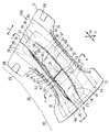
図1は、一例として示す使い捨ておむつ20Aの斜視図である。図2は、第1および第2パネル22,23の側から示す図1のおむつ20Aの部分破断平面図である。図3は、図1の3−3線矢視断面図である。図4は、図1の4−4線矢視断面図である。図1,2では、横方向を矢印L、縦方向を矢印Mで示し、厚み方向を矢印N(図1のみ)で示す。図2は、おむつ20Aを弾性部材33,65の収縮力に抗して縦横方向へ展開させた状態で示している。
FIG. 1 is a perspective view of a
おむつ20Aは、不透液性シャーシ21と、シャーシ21の内側に配置されて縦方向Mへ前後に並ぶ第1および第2体液吸収性パネル22,23を含む。おむつ20Aは、シャーシ21の内側に配置されて縦方向Mへ延びる一対の不透液性防漏シート24を有する。The diaper 20 </ b> A includes a liquid-
シャーシ21は、肌当接側に位置する疎水性繊維不織布25と肌非当接側に位置する通気不透液性プラスチックフィルム26とをラミネートした複合シートから形成されており、不織布25とフィルム26とは、それらの対向面が固着されている。シャーシ21は、縦方向Mに前胴周り域27および後胴周り域29と、それら胴周り域27,29の間に位置する股下域28とを有する。シャーシ21は、前後胴周り域27,29に位置して横方向Lへ延びる前後端部30,31と、前後胴周り域27,29間に縦方向Mへ延びる両側部32とを有する。股下域28では、おむつ20Aがほぼ砂時計型を呈するように、両側部32がシャーシ21の横方向内方へ向かって弧を画いている。シャーシ21には、股下域28の両側部32に位置して縦方向Mへ延びる複数条の脚周り用弾性部材33が収縮可能に取り付けられている。脚周り用弾性部材33は、不織布25とフィルム26との間に介在し、縦方向Mへ所定の倍率に伸長された状態で不織布25とフィルム26との対向面に固着されている。The
第1パネル22は、縦方向へ長い矩形を呈し、防漏シート24の後記する先端部63の間であってシャーシ21の股下域28と後胴周り域29とに位置している。第1パネル22は、肌当接側に位置する透液性シート34(透液性第1シート)と、肌非当接側に位置する不透液性シート35と、透液性シート34と不透液性シート35との間に介在してそれらシート34,35の内面に接合された吸液性コア36(吸液性第1コア)とから構成されている。コア36は、その上面全体が透液性シート34に被覆され、その下面全体が不透液性シート35に被覆されている。
The
第1パネル22は、シャーシ21の股下域28に固着された前部37と、シャーシ21の後胴周りに固着された後部38と、シャーシ21の両側部32に固着された両側縁部39とを有する。前後部37,38は、その大部分がシート34,35とコア36とから形成されている。両側縁部39は、互いに重なり合うシート34,35から形成されている。前後部37,38と両側縁部39とでは、不透液性シート35がシャーシ21に固着されている。前部37は、後胴周り域29の側から前胴周り域27の側へ向かって延び、股下域28の略前半分に位置している。後部38は、シャーシ21の後部38に位置している。The
第1パネル22では、コア36の縦方向両端縁40から縦方向外方へシート34,35の縦方向端部41,42が延び、コア36の両側縁43から横方向外方へシート34,35の両側部44,45が延びている。それらシート34,35の端部41,42が互いに重なり合って内面どうしが固着され、それらシート34,35の側部44,45が互いに重なり合って内面どうしが固着されている。
In the
第2パネル23は、縦方向Mへ長い矩形を呈し、防漏シート24の先端部63の間であってシャーシ21の前胴周り域27と股下域28とに位置している。第2パネル23は、肌当接側に位置する透液性シート46(透液性第2シート)と、肌非当接側に位置する透液性シート47(透液性第2シート)と、透液性シート46,47の間に介在してそれらシート46,47の内面に接合された吸液性コア48(吸液性第2コア)とから構成されている。コア48は、その上面全体が透液性シート46に被覆され、その下面全体が透液性シート47に被覆されている。The
第2パネル23は、シャーシ21の前胴周り域27に固着された前部49と、シャーシ21の股下域28に位置する先端部50と、シャーシ21の両側部32に固着された両側縁部51(両側縁部)とを有する。前部49および先端部50は、シート46,47とコア48とから形成されている。両側縁部51は、互いに重なり合うシート46,47から形成されている。前部49と両側縁51とでは、透液性シート47の外面がシャーシ21に固着されている。前部49は、前胴周り域27の側から後胴周り域29の側へ向かって延び、股下域28の略前半分に位置している。先端部50は、シャーシ21の前胴周り域27の略前半分に位置し、シャーシ21に固着されていない。The
第2パネル23の先端部50は、シャーシ21の両側部32の側に位置する一対の両側部分52と、両側部分52の間に位置する中間部分53とから形成されている。両側部分52と中間部分53とは、シート46,47とコア48とから形成されている。両側部分52と中間部分53とは、シャーシ21から上方へ延び、シャーシ21の上方へ凸となるように弧を画いている。具体的には、先端部50は、基端部につながる領域においてシャーシ21に対して所定の角度、好ましくは5°〜60°、より好ましくは15°〜45°の角度で上向きに折れ曲がってシャーシ21から離間している。折曲領域は、エンボス処理によって形成される。先端部は、両側部分52を、それらが互いに近づくように引き寄せることによって、および凸形の状態でシャーシ21上に固定することによって、上方に凸となっていてもよい。股下域28から後胴周り域29に向かって開口するポケット54が、シャーシ21と第2パネル23の先端部50との間に形成されている。ポケット54は、股下域28の縦方向の中央付近から股下域28の略前半分に延びている。第2パネル23の先端部50の下方には、第1パネル22の前部37の先端部分55が、ポケット54内に延びている。
The
第2パネル23では、コア48の縦方向両端縁56から縦方向外方へシート46,47の縦方向両端部57,58が延び、コア48の両側縁59から横方向外方へシート46,47の両側部60,61が延びている。第2パネル23では、それらシート46,47の端部57,58が互いに重なり合って内面どうしが固着され、それらシート46,47の側部60,61が互いに重なり合って内面どうしが固着されている。先端部50では、シート46,47の端部57,58がコア48の下面に向かって折り曲げられている。
In the
防漏シート24は、シャーシ21の両側部32に配置されており、縦方向へ延びる基側部62と、固定側部62に並行して縦方向へ延びていてシャーシ21の上方へ起立性向を有する先端部63と、前後端部30,31に位置してシャーシ21の横方向内方へ倒伏した縦方向両端部64とを含む。基側部62と先端部63とは、シャーシ21の前後端部30,31間に延びている。先端部63は、縦方向へ延びる伸縮性弾性部材65が収縮可能に取り付けられた先端縁66と、先端縁66から基側部62に延びる中央部分67とを有する。弾性部材65は、縦方向へ所定の倍率に伸長された状態で先端縁66に固着されている。おむつ20Aがシャーシ21の内面を内側にして縦方向へ湾曲して弾性部材65が収縮すると、先端縁66が縦方向へ縮み、先端部63がシャーシ21の上方へ起立して排泄物に対する障壁を形成する。
The leak-
前端部30では、防漏シート24の端部64内面がシャーシ21に固着され、透液性シート46,47の端部57,58がシャーシ21と防漏シート24の端部64との間に介在してそれら要素21,24の内外面に固着されている。後端部31では、防漏シート24の端部64内面がシャーシ21に固着され、透液性シート34と不透液性シート35との端部がシャーシ21と防漏シート24の端部64との間に介在してそれら要素21,24の内外面に固着されている。両側部32では、防漏シート24の側部62内面がシャーシ21の内面に固着され、透液性シート34,46,47と不透液性シート35との側部44,45,60,61がシャーシ21と防漏シート24の側部62との間に介在してそれら要素21,24の内外面に固着されている。
At the
後胴周り域29の両側部32には、繊維不織布から形成された一対の可撓性テープファスナ68が取り付けられている。テープファスナ68は、横方向へ延びる基端部69と先端部70とを有する。基端部69は、不織布25とフィルム26との間に介在し、それらの対向面に固着されている。先端部70の内面には、フック部材71が設けられている。先端部70は、おむつ20Aの横方向内方へ折曲され、フック部材71を介してシャーシ21の不織布25に仮止めされている。なお、先端部70には、フック部材71ではなく、感圧型接着剤が塗布されていてもよい。
A pair of
前胴周り域27には、テープファスナ68の先端部70を着脱可能に止着する可撓性のターゲットテープ72が取り付けられている。ターゲットテープ72は、横長矩形を呈し、繊維シャーシとシャーシから突出するループ部材(図示せず)とから形成されている。ターゲットテープ72は、シャーシ21の外面に固着されている。テープファスナ68の先端部70に感圧型接着剤を塗布する場合は、ターゲットテープ72にプラスチックフィルムが使用される。
A
おむつ20Aを着用するには、後胴周り域29の両側部32を前胴周り域27の両側部32の外側に重ね合わせ、フック部材71を介してテープファスナ68の先端部70をターゲットテープ72に止着して前胴周り域27と後胴周り域29とを連結する。このようにして前後胴周り域27,29が連結されたおむつ20Aには、胴周り開口とその下方に一対の脚周り開口とが形成される(図示せず)。着用者の身につけられたおむつ20Aの前胴周り域27と股下域28の前半分とに排泄された尿は、第2パネル23のコア48に吸収保持され、股下域28の後半分と後胴周り域29とに排泄された大便の水分は、第1パネル22のコア36に吸収保持される。前胴周り域27に向かって流動した大便は、ポケット54に収容される。尿が速やかに吸収されるように、第2パネル23の液吸収性および液拡散性が第1パネル22よりも高いことが好ましい。
In order to wear the diaper 20 </ b> A, both
第2パネル23の先端部50がシャーシ21の上方へ起立し、シャーシ21と先端部50との間に股下域28から後胴周り域29に向かって開口するポケット54が形成されている。このように、股下域28の後半分や後胴周り域29に排泄された大便が前胴周り域27に向かって流動したとしても、ポケット54が大便を収容することができる。おむつ20Aは、背景技術のおむつと比較し、排泄された多量の大便を収容することができる。
A
おむつ20Aは、尿が第2パネル23に吸収保持され、大便が第1パネル22に吸収保持されるとともにポケット54に収容される。このように、尿と大便とが分離され、尿と大便とが混ざり合うことによる着用者の肌の汚れを防ぐことができる。さらに、前後胴周り域27,29において第1および第2パネル22,23が、嵩張るように重なり合うことがなく、着用したおむつ20Aに対する違和感がない。
In the diaper 20 </ b> A, urine is absorbed and held by the
第2パネル23の先端部50が着用者の性器と肛門との間に位置するから、尿および大便が互いに分離され、尿と大便とが混ざり合うことによる着用者の肌の汚れを防ぐことができる。第1パネル22の前部37の先端部分55が第2パネル23の先端部50の下方に延び、ポケット54内に延びている。そのような構成によって、たとえ尿がポケット54内へ第2パネルを透過したとしても、ポケット54において尿や大便が第1パネル22のコア36に吸収保持されるので尿と大便とが混ざり合うことを防ぐことができる。
Since the front-end | tip
防漏シート24の先端部63が尿に対する障壁を形成するので、第1および第2パネル22,23の上面(透液性シート34,46の上面)を拡散する尿が両側縁部39,51に向かって流動したとしても、尿の流動が先端部63によって阻止され、シャーシ21の両側部からの尿の横漏れを防ぐことができる。
Since the
図5は、他の一例として示す使い捨ておむつ20Bの斜視図であり、図6は、第1および第2パネル22,23の側から示す図5のおむつ20Bの部分破断平面図である。図7は、図5の7−7線矢視断面図であり、図8は、図5の8−8線矢視断面図である。図5,6では、横方向を矢印L、縦方向を矢印Mで示し、厚み方向を矢印N(図5のみ)で示す。図6は、おむつ20Bを弾性部材33,65,74の収縮力に抗して縦横方向へ展開させた状態で示している。
FIG. 5 is a perspective view of a disposable diaper 20B shown as another example, and FIG. 6 is a partially broken plan view of the diaper 20B of FIG. 5 shown from the first and
このおむつ20Bが図1のそれと異なるのはポケット54に横方向へ延びるスペーサ73が配置されている点であり、その他の構成は図1−4のおむつ20Aと同一であるので、図1−4のおむつ20Aと同一の符合を付してその他の構成の説明は省略する。
This diaper 20B is different from that of FIG. 1 in that a
スペーサ73は、横方向へ弾性的な伸縮性を有してポケット54に収縮可能に配置されている。具体的には、スペーサ73は、横方向へ延びる複数条の伸縮性弾性部材74が収縮可能に取り付けられた透水性シート75から形成されている。弾性部材74は、横方向へ所定の倍率に伸長させた状態でシート75に固着されている。スペーサ73は、第2パネル23の先端部50の両側部分52に固着された固定両端部76と、それら端部76の間に延びる中間部77とを有する。第2パネル23の先端部50の両側部分52は、スペーサ73の収縮力によってシャーシ21の横方向内方へ引き寄せられている。
The
スペーサ73の固定両端部76は、先端部50の両側部分52に固着されることなく、シャーシ21と防漏シート24との間に介在してシート31の側部32とシート24の側部62とに固着されていてもよい。スペーサ73の両端部76は、シャーシ21と防漏シート24との間に介在してシート21の側部32とシート24の側部62とに固着されるとともに、先端部50の両側部分52に固着されていてもよい。
The
発明の範囲を逸脱することなく、スペーサ73に、弾性部材を省いた伸縮性の透水性シート、例えば、伸縮性かつ親水性繊維不織布を使用することもできる。また、スペーサ73には、非伸縮性の透水性シート、例えば、非伸縮性かつ親水性繊維不織布のみを使用することもできる。スペーサ73に非伸縮性の透水性シートを使用する場合は、先端部50の両側部分52がシャーシ21の横方向内方へ引き寄せられるように、スペーサ73の横寸法をコア48の横寸法よりも小さくする。
Without departing from the scope of the invention, the
スペーサ73の収縮力下でシャーシ21の横方向内方へ引き寄せられると、先端部50の両側部分52は、シャーシ21から上方へ延び、シャーシ21の上方へ凸となるように弧を画いている。その結果、第2パネル23の先端部50の中間部分53は、両側部分52の上方へ凸となるように弧を画いている。
When pulled inward in the lateral direction of the
おむつ20Bでは、スペーサ73の収縮力によって第2パネル23の先端部50の両側部分52がシャーシ21の横方向内方へ引き寄せられ、それによって先端部50の形態が上向き凸形状に維持される。換言すれば、シャーシ21の上方へ延びる両側部分52が不用意に倒伏することがない。このように、シャーシ21と第2パネル23の先端部50との間に形成されたポケット54の形態が、スペーサ73の収縮力の下に確実に保持される。おむつ20Bは、ポケット54が、その口を閉じ難く、大便を確実に収容することができる。おむつ20Bの厚み方向へ着用者の体圧がかかり、第2パネル23の先端部50が潰れたとしても、体圧が解除されると、スペーサ73の伸縮力によって先端部50がシャーシ21の上方へ凸となるように起立し、シャーシ21と先端部50との間に再びポケット54が形成される。
In the diaper 20 </ b> B, both
スペーサ73の収縮時における横寸法が第2パネル23を形成するコア48の両側縁59間の横寸法L1に対して20〜93%の範囲、より好ましくは、50〜80%の範囲にある。
The lateral dimension when the
弾性部材74を含むスペーサ73の100〜250%伸長時における横方向伸長応力が0.5〜1.5Nの範囲にある。スペーサ73の伸長応力が0.5N未満であると、スペーサ73の収縮力によって先端部50の両側部分52をシャーシ21の横方向内方へ十分に引き寄せることができず、おむつ20Bの厚み方向へわずかな体圧がかかっただけで第2パネル23の先端部50が容易に潰れ、ポケットがその口を閉じてしまう場合がある。スペーサの伸長応力が1.5Nを超過すると、股下域28が横方向内方へ必要以上に縮み、シャーシ21や第1パネル22の前部37、第2パネル23の先端部50に多数の不規則なギャザーが形成される。これらの不規則なギャザーは、ポケット54の好ましい形態を保持することができないのみならず、股下域28における第1および第2パネル22,23の体液吸収機能が低下する。その結果、股下域28において尿や大便を十分に吸収することができない。スペーサ73の伸長応力が前記範囲にあるおむつ20Bは、シャーシ21と第2パネル23の先端部50との間に形成されたポケット54の形態を確実に保持することができ、股下域における第1および第2パネル22,23の体液吸収機能が低下することがない。スペーサ73の伸長応力は、以下の方法で測定した。
(1)スペーサ73(弾性部材74を含む)をおむつ20Bから分離し、スペーサ73を裁断して縦寸法30mm、横寸法100mmの伸長応力測定用サンプルを作成した。日本の島津製作所社製の引張り試験機を使用した。
(2)弾性部材の収縮によって縮んだ状態のサンプルの横方向両端部を引張り試験機のチャックで挟み(チャック間寸法:約30mm)、100mm/minの速度でサンプルを横方向へ引っ張り、サンプルを260%まで伸長させた後、伸長状態を解除した。再度、試験機を介して100mm/minの速度でサンプルを横方向へ引っ張り、サンプルを100〜250%の範囲で伸長させ、そのときの試験機にかかる力を測定し、その測定値をスペーサ73の横方向伸長応力とした。このようにして測定したサンプルの横方向伸長応力は、0.5〜1.5Nであった。ここで、サンプルを200%まで伸長させるとは、たとえば、サンプルの横寸法が30mmの場合、30mmに2.0を乗じた値である60mmまで伸ばすことをいう。
The lateral extension stress when the
(1) The spacer 73 (including the elastic member 74) was separated from the diaper 20B, and the
(2) Both ends of the sample in the contracted state due to the contraction of the elastic member are sandwiched between chucks of a tensile tester (dimension between chucks: about 30 mm), and the sample is pulled laterally at a speed of 100 mm / min. After extending to 260%, the extended state was released. Again, the sample was pulled laterally through the testing machine at a speed of 100 mm / min, the sample was stretched in the range of 100 to 250%, the force applied to the testing machine at that time was measured, and the measured value was used as the
図9は、他の一例として示す使い捨ておむつ20Cの斜視図であり、図10は、第1および第2パネル22,23の側から示す図9のおむつ20Cの部分破断平面図である。図11は、図9の11−11線矢視断面図であり、図12は、図9の12−12線矢視断面図である。図9,10では、横方向を矢印L、縦方向を矢印Mで示し、厚み方向を矢印N(図9のみ)で示す。図10は、おむつ20Cを弾性部材33,65の収縮力に抗して縦横方向へ展開させた状態で示している。
FIG. 9 is a perspective view of a disposable diaper 20C shown as another example, and FIG. 10 is a partially cutaway plan view of the diaper 20C of FIG. 9 shown from the first and
おむつ20Cは、さらに、シャーシ21の内側に配置されて縦方向へ延びる一対の不透液性防漏シート24を有する。このおむつ20Cが図1のそれと異なるのは、第2パネル23の先端部50の両側部分52が防漏シート24の先端部63に連結されている点であり、その他の構成は図1−4のおむつ20Aと同一であるので、図1−4のおむつ20Aと同一の符合を付してその他の構成の説明は省略する。
The diaper 20 </ b> C further includes a pair of liquid-impervious leak-
第2パネル23の先端部50の両側部分52は、その一部が防漏シート24の先端部63の先端縁66の側に位置する中央部分67に連結されている。両側部分52では、透液性シート46の外面が接着剤78を介して防漏シート24に固着されている。先端縁66は、先端部50の両側部分52の上方に延出している。先端部50の中間部分53の頂点79は、先端縁66の上方に位置している。防漏シート24の先端部63は、シャーシ21の上方へ起立して排泄物に対する障壁を形成するとともに、それによって先端部63の両側部分52をシャーシ21の上方へ持ち上げている。先端部50の両側部分52の全体が先端部63の中央部分67に連結されていてもよく、防漏シート24の先端縁66を含む先端部63全体が先端部50の両側部分52に連結されていてもよい。
A part of the both
防漏シート24の先端部63によって持ち上げられた両側部分52は、凸となるように弧を画くようにシャーシ21の上方へ延びている。したがって、中間部分53は、凸となるように弧を画くように両側部分52の上方へ延びている。シャーシ21と第2パネル23の先端部50との間には、股下域28から後胴周り域29に向かって開口するポケット54が形成されている。ポケット54は、股下域28の縦方向の略中央から略前半分に延びている。第1パネル22の前部37の先端部分55が第2パネル23の先端部50の下方に位置し、ポケット54内に延びている。
Both
防漏シート24の先端部63がシャーシ21の上方へ起立すると、第2パネル23の先端部50がシャーシ21の上方へ起立する。シャーシ21の上方に延びる両側部分52が不用意に倒伏することがないので、シャーシ21の上方へ凸となる先端部50の形態が、防漏シート24の先端部63によって確実に保持される。このように、防漏シート24の先端部63は、シャーシ21と第2パネル23の先端部50との間に形成されたポケット54の形態を確実に保持することができる。おむつ20Cは、ポケット54がその口を閉じ難く、大便を確実に収容することができる。
When the
おむつ20Cは、防漏シート24の先端部63が尿に対する障壁を形成するので、第1パネル22の上面(透液性シート34の上面)を拡散する尿が両側縁部39に向かって流動したとしても、シャーシ21の両側部からの尿の横漏れを防ぐことができる。
In the diaper 20 </ b> C, the
防漏シート24の先端部63の先端縁66が、先端部50の両側部分52の上方に延び、それによって排泄物に対する障壁を形成する。第2パネル23の先端部50の上面(透液性シート46の上面)を拡散する尿が両側部分52に向かって流動したとしても、尿の流動が先端縁66によって阻止され、それによって先端部50の両側部分52からの尿の横漏れを防ぐことができる。先端部50の中間部分53の頂点79が先端縁66の上方に位置しているので、先端部50の中間部分53の頂点79が先端縁66よりも先に着用者の股間部に当接する。その結果、先端縁66がおむつ20Cの横方向へ倒伏することがなく、先端縁66が尿に対する障壁としての機能を失うことがない。
The leading
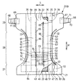
図13は、他の一例として示す使い捨ておむつ20Dの斜視図であり、図14は、第1および第2パネル22,23の側から示す図13のおむつ20Dの部分破断平面図とであり、図15は、図13の15−15線矢視断面図であり、図16は、図13の16−16線矢視断面図である。図13,14では、横方向を矢印L、縦方向を矢印Mで示し、厚み方向を矢印N(図13のみ)で示す。図14は、おむつ20Dを弾性部材33,65の収縮力に抗して縦横方向へ展開させた状態で示している。
13 is a perspective view of a
おむつ20Dが図1―4のおむつ20Aと異なるのは、第1および第2パネル22,23に折曲案内部80,83が形成されている点、ポケット54に横方向へ延びるスペーサ73が配置されている点、第2パネル23の先端部50の両側部分52が防漏シート24の先端部63に連結されている点である。その他の構成は図1−4のおむつ20Aと同一であるので、図1−4のおむつ20Aと同一の符合を付してその他の構成の説明は省略する。
The
第1パネル22の前部37には、横方向へ所定寸法離間して縦方向へ延びる一対の折曲案内部80が形成されている。具体的には、折曲案内部80は、シャーシ21の横方向内方へ弧を画き、前部37から両縁側部39に延びている。前部37は、折曲案内部80の両側に位置する両側部分81と、折曲案内部80の間に位置する中間部分82とに区画されている。前部37は、折曲案内部80を介して折れ曲がっている。前部37の両側部分81と中間部分82とは、シャーシ21とともにおむつ20Dの厚み方向下方へ向かって凸となるように弧を画いている。
The
第2パネル23の先端部50における両側部分52と中間部分53との間には、横方向へ所定寸法離間して縦方向に延びる一対の折曲案内部83が形成されている。具体的には、これらの折曲案内部83は、シャーシ21の横方向内方へ弧を画き、先端部50から両側縁部51に延びている。先端部50は、折曲案内部83を介して折れ曲がっている。
Between the both
それら折曲案内部80,83では、第1および第2パネル22,23を形成するコア36,48は、折曲案内部80,83を除く第1パネル22の前部37と第2パネル23の先端部50とのコア36,48よりも小さい密度や坪量、厚み寸法を有する。ゆえに、それら折曲案内部80,83における第1および第2パネル22,23の剛性は、折曲案内部80,83を除く第1パネル22の前部37(コア36を含む)と第2パネル23の先端部50(コア48を含む)とのそれよりも低い。それら折曲案内部80,83では、第1および第2パネル22,23を形成するコア36,48の密度や坪量、厚み寸法のうちの少なくとも密度と坪量とを折曲案内部80,83を除く第1パネル22の前部37と第2パネル23の先端部50とのコア36,48のそれらよりも小さくすることで、それら折曲案内部80,83における第1および第2パネル22,23の剛性を折曲案内部80,83を除く第1パネル22の前部37(コア36を含む)と第2パネル23の先端部50(コア48を含む)とのそれよりも低くすることができる。
In the bending
それら折曲案内部80,83は、コア36,48が存在せず、すなわち折曲案内部80がコア36を除く透液性シート34と不透液性シート35のみから形成され、折曲案内部83がコア48を除く透液性シート46,47のみから形成されていてもよい。発明の範囲を逸脱することなく、第1および第2パネル22,23において、折曲案内部80が前部37から両側縁部39に達することなく、前部37を縦方向に延びていてもよく、折曲案内部83が先端部50から両側縁部51に達することなく、先端部50を縦方向に延びていてもよい。
The bending
スペーサ73は、横方向へ弾性的な伸縮性を有してポケット54に収縮可能に配置されている。具体的には、スペーサ73は、縦方向に所定寸法離間して横方向へ延びる複数条の伸縮性弾性部材74が収縮可能に取り付けられた透水性シート75から形成されている。弾性部材74は、横方向へ所定の倍率に伸長させた状態でシート75に固着されている。スペーサ73は、第2パネル23の先端部50の両側部分52に固着された固定両端部76と、固定両端部76の間に延びる自由中間部77とを有する。先端部50の両側部分52は、スペーサ73の収縮力によってベースシート21の横方向内方へ引き寄せられている。
The
第2パネル23の先端部50の両側部分52は、防漏シート24の先端部63の先端縁66の側に位置する中央部分67に連結されている。両側部分52では、透液性シート46の外面が接着剤78を介して防漏シート24に固着されている。先端縁66は、先端部50の両側部分52の上方に延びている。先端部50の中間部分53の頂点79は、先端縁の上方に位置している。先端部63は、シャーシ21の上方へ起立して排泄物に対する障壁を形成し、それによって先端部50の両側部分52をシャーシ21の上方へ持ち上げている。
Both
先端部50の両側部分52は、折曲案内部83を介して折れ曲がるとともに、スペーサ73によってシャーシ21の横方向内方へ引き寄せられ、防漏シート24の先端部63によってシャーシ21の上方へ持ち上げられている。先端部50では、両側部分52がシャーシ21の上方へ延び、中間部分53が両側部分52の上方へ凸となるように弧を画いている。シャーシ21と第2パネル23の先端部50との間には、股下域28から後胴周り域29に向かって開口するポケット54が形成されている。第2パネル23の自由後部50の下方で、第1パネル22の前部37の先端部分55がポケット54内に延びている。先端部分55は、シャーシ21とともにおむつ20Dの厚み方向下方に凸となってポケット54を形成している。
Both
第1パネル22の前部37がシャーシ21とともにおむつ20Dの厚み方向下方へ凸となるとともに、第2パネル23の先端部50がシャーシ21の上方へ向かって凸となり、シャーシ21と先端部50との間に股下域28から後胴周り域29に向かって開口するポケット54が形成されている。そのような構成によって、股下域28の後半分や後胴周り域29に排泄された大便が前胴周り域27に向かって流動したとしても、ポケットに収容することができる。第1パネル22の固定前部37がシャーシ21とともにおむつ20Dの厚み方向下方へ凸となるように弧を画いている。そのような構成によって、図1,5,9のおむつ20A,20B,20Cと比較し、ポケット54のより大きな大便収容容積を確保することができる。このように、おむつ20D上に排泄された多量の大便をポケット54に確実に収容することができる。
The
折曲案内部83が第2パネル23の先端部50から両側縁部51に延び、先端部50が折曲案内部83を介して折れ曲がることで、第2パネル23の先端部50が折曲案内部83の両側に位置する両側部分52と折曲案内部83の間に位置する中間部分53とに明確に区画され、折曲案内部83の両側に位置する両側部分52がシャーシ21の上方へ起立し易い。それによって、折曲案内部83の両側に位置する両側部分52がシャーシ21の上方へ起立し易く、第2パネル23の先端部50がシャーシ21の上方へ容易に凸となる。このように、シャーシ21と第2パネル23の先端部50との間にポケット54が確実に形成される。
The bending
ポケット54に、横方向へ弾性的な伸縮性を有して収縮可能なスペーサ73が配置されている。先端部50の両側部分52が、スペーサ73の収縮力によってシャーシ21の横方向内方へ引き寄せられ、先端部50が上方へ凸の形状に維持される。換言すれば、シャーシ21の上方へ起立している両側部分52は、不用意に倒伏することがない。このように、シャーシ21と第2パネル23の先端部50との間に形成されたポケット54の形状は、スペーサ73の収縮力によって確実に維持される。おむつ20Dの厚み方向へ着用者の体圧がかかり、第2パネル23の先端部50が潰れたとしても、おむつ20Dが体圧から解放されると、スペーサ73の伸縮力によって先端部50がシャーシ21の上方へ凸となるように起立し、シャーシ21と先端部50との間に再びポケット54が形成される。
In the
シャーシ21の上方へ起立している防漏シート24の先端部63が、シャーシ24の上方へ起立するように第2パネル21の先端部50を持ち上げ、先端部50は、防漏シート24の先端部63によって上方へ凸の形状に維持され、シャーシ21の上方へ延びている先端部50の両側部分52が不用意に倒伏することが防止される。その結果、防漏シート24の先端部63が、シャーシ21と先端部50との間に形成されたポケット54を好ましい形態に維持することができる。
The
おむつ20Dにおいてもまた、防漏シート24の先端部63によって形成された尿に対する障壁が、第1パネル22の上面(透液性シート34の上面)を拡散する尿が両側縁部39に向かって流動したとしても、シャーシ21の両側部からの尿の横漏れを防ぐことができる。
Also in the diaper 20 </ b> D, the urine that diffuses the upper surface of the first panel 22 (the upper surface of the liquid-permeable sheet 34) from the urine formed by the
おむつ20Dにおいてもまた、防漏シート24の先端部63の先端縁が、先端部50の両側部分52の上方に延び、尿に対する障壁を形成する。先端部50の上面(透液性シート46の上面)を拡散する尿が両側部分52に向かって流動したとしても、先端縁66が、先端部50の両側部分52からの尿の横漏れを防ぐことができる。先端部50の中間部分53の頂点79が先端縁66の上方に位置している。そのような独自の構成によって、中間部分の頂点79が先端縁66よりも先に着用者の股間部に当接する。その結果、先端縁66がおむつ20Dの横方向へ倒伏することがなく、先端縁66が尿に対する障壁としての機能を失うことがない。
Also in the diaper 20 </ b> D, the leading edge of the
先端部50の両側部分52をシャーシ21の横方向内方へ引き寄せるスペーサ73は、先端部50の両側部分52を起立させる防漏シート24の先端部63とともに、ポケット54が、その閉じ難く、大便を確実に収容することを確実にする。
The
折曲案内部83を含む第2パネル23の先端部50(コア48を含む)の横方向の剛性値が0.5〜1.5mNの範囲にあり、折曲案内部83を除く第2パネル23の先端部50(コア48を含む)の剛性値が1.0〜2.0mNの範囲にある。折曲案内部83を含む先端部50の剛性値が1.5mNを超過すると、先端部50が折曲案内部83において折れ曲がり難く、両側部分52がシャーシ21の上方へ起立し難くなる。折曲案内部83を除く第2パネル23の先端部50の剛性値が1.0mN未満では、スペーサ73の収縮力によって先端部50が折曲案内部83を介してシャーシ21の横方向内方へ必要以上に縮む。その結果、ポケット54の形態を保持することができないのみならず、股下域28における第1および第2パネル22,23の体液吸収機能が低下し、股下域28において尿を十分に吸収することができない。折曲案内部を除く第2パネル23の自由後部50の剛性値が2.0mNを超過すると、第2パネルの柔軟性が低下し、着用者の股間部に当接する第2パネル23が着用者に不快な刺激を与える場合がある。これらの剛性値は、ガーレ法(JIS L 1096−01−8.20.1)に準拠して以下のように測定した。
(1)おむつ20Dから第2パネル23を分離し、第2パネルを裁断して縦寸法25mm、横寸法30mmの剛性値測定用サンプルを作成した。サンプルは、折曲案内部83を含む第1サンプルと、折曲案内部83を除く第2サンプル(コア48を含む)とを用意した。曲げ剛性の測定には、ガーレ柔軟度試験機を使用した。
(2)第1サンプルの縦方向一端部を試験機のチャックに挟み、第1サンプルの縦方向他端部を試験機の振り子にかけ、試験機の目盛りが3〜6の間になるように補助重りを取り付けた。試験機のスイッチを入れ、第1サンプルから振り子の回転ロッドが離れる瞬間の目盛りを読み、第1剛性値を測定した。次に、第1サンプルの縦方向他端部を試験機のチャックに挟み、第1サンプルの縦方向一端部を試験機の振り子にかけ、試験機の目盛りが3〜6の間になるように補助重りを取り付けた。次に、試験機のスイッチを入れ、第1サンプルから振り子の回転ロッドが離れる瞬間の目盛りを読み、第2剛性値を測定した。測定した第1および第2剛性値の平均を第1サンプルの曲げ剛性値とし、第1サンプルの曲げ剛性値を折曲案内部83を含む第2パネル23の先端部50の剛性値とした。第1サンプルの曲げ剛性値は0.5〜1.5mNであった。
(3)第2サンプルの縦方向一端部を試験機のチャックに挟み、第2サンプルの縦方向他端部を試験機の振り子にかけ、試験機の目盛りが3〜6の間になるように補助重りを取り付けた。試験機のスイッチを入れ、第2サンプルから振り子の回転ロッドが離れる瞬間の目盛りを読み、第3剛性値を測定した。次に、第2サンプルの縦方向他端部を試験機のチャックに挟み、第2サンプルの縦方向一端部を試験機の振り子にかけ、試験機の目盛りが3〜6の間になるように補助重りを取り付けた。次に、試験機のスイッチを入れ、第2サンプルから振り子の回転ロッドが離れる瞬間の目盛りを読み、第4剛性値を測定した。測定した第3および第4剛性値の平均を第2サンプルの曲げ剛性値とし、第2サンプルの曲げ剛性値を折曲案内部83を除く第2パネル23の先端部50(コア48を含む)の剛性値とした。第2サンプルの曲げ剛性値は1.0〜2.0mNであった。
The second panel excluding the bending
(1) The
(2) One end of the first sample in the vertical direction is sandwiched between chucks of the testing machine, and the other end of the first sample in the vertical direction is placed on the pendulum of the testing machine, so that the scale of the testing machine is between 3 and 6. A weight was attached. The test machine was turned on, the scale at the moment when the pendulum rotating rod separated from the first sample was read, and the first stiffness value was measured. Next, the other end of the first sample in the vertical direction is sandwiched between chucks of the testing machine, and the one end of the first sample in the vertical direction is applied to the pendulum of the testing machine so that the scale of the testing machine is between 3 and 6. A weight was attached. Next, the test machine was turned on, the scale at the moment when the rotating rod of the pendulum separated from the first sample was read, and the second stiffness value was measured. The average of the measured first and second stiffness values was taken as the bending stiffness value of the first sample, and the bending stiffness value of the first sample was taken as the stiffness value of the
(3) One end of the second sample in the vertical direction is sandwiched between chucks of the testing machine, and the other end of the second sample in the vertical direction is applied to the pendulum of the testing machine, so that the scale of the testing machine is between 3 and 6. A weight was attached. The test machine was turned on, the scale at the moment the rotating rod of the pendulum was separated from the second sample was read, and the third stiffness value was measured. Next, the other vertical end of the second sample is sandwiched between chucks of the testing machine, and the vertical one end of the second sample is placed on the pendulum of the testing machine so that the scale of the testing machine is between 3 and 6. A weight was attached. Next, the test machine was turned on, the scale at the moment when the rotating rod of the pendulum separated from the second sample was read, and the fourth stiffness value was measured. The average of the measured third and fourth stiffness values is the bending stiffness value of the second sample, and the bending stiffness value of the second sample is the tip portion 50 (including the core 48) of the
このおむつ20Dは、折曲案内部80,83における第1および第2パネル22,23の剛性が折曲案内部80,83を除く第1パネル22の固定前部37と第2パネル23の先端部50とのそれより高くてもよい。それら折曲案内部80,83における剛性を折曲案内部80,83を除く前部37と先端部50とのそれより高くする一例は、折曲案内部80,83において第1および第2パネル22,23が厚み方向に圧縮され、折曲案内部80,83におけるコア36,48の密度および/または坪量が大きくされればよい。この場合は、固定前部37が折曲案内部80の両側で折れ曲がって両側部分81と中間部分82とに区画され、先端部50が折曲案内部83の両側で折れ曲がる。
In the
おむつ20A,20B,20C,20Dは、第2パネル23の前部49がシャーシ21の前胴周り域27に固着されているが、前部49がシャーシ21の前端部30のみに固着されていてもよい。図9,13に示すおむつ20C,20Dは、第2パネル23の両側縁部51がシャーシ21の両側部32に固着されているが、先端部分付近の両側縁部51のみがシャーシ21の両側部32に固着されていればよく、両側縁部51の全体がシャーシ21の両側部32に固着されていなくてもよい。
In the diapers 20 </ b> A, 20 </ b> B, 20 </ b> C, 20 </ b> D, the
それらおむつ20A,20B,20C,20Dは、それらの縦寸法を二分する横中心線で前半分と後半分とに分けられるとともに、前半分がさらに横分割線で横中心線寄りに位置する中央部分と横中心線から離れた端部分とに分けられたときに、先端部50がおむつ20A,20B,20C,20Dの中央部分の範囲に位置していればよい。
The
透液性シート34,46,47には、親水性繊維不織布、多数の開孔を有する疎水性繊維不織布、微細な多数の開孔を有するプラスチックフィルムのいずれかを使用することができる。防漏シート24や不透液性シート35には、疎水性繊維不織布、通気不透液性プラスチックフィルム、2枚以上の疎水性繊維不織布をラミネートした複合不織布、疎水性繊維不織布と通気不透液性プラスチックフィルムとをラミネートした複合シートのいずれかを使用することができる。シャーシ21や防漏シート24、不透液性シート35には、高い耐水性を有するメルトブローン不織布の両面または片面に高い強度と良好な柔軟性とを有するスパンボンド不織布を重ね合わせた複合不織布(SM不織布、SMS不織布、SMMS不織布)を使用することもできる。
As the liquid-
繊維不織布には、スパンレース、ニードルパンチ、メルトブローン、サーマルボンド、スパンボンド、ケミカルボンドの各製法により製造された不織布を使用することができる。不織布の構成繊維には、ポリエステル系、ポリアクリロニトリル系、ポリ塩化ビニル系、ポリエチレン系、ポリプロピレン系、ポリスチレン系繊維を使用することができる。構成繊維には、芯鞘型複合繊維、並列型複合繊維、異型中空繊維、微多孔繊維、接合型複合繊維を使用することもできる。 As the fiber nonwoven fabric, a nonwoven fabric produced by each method of spunlace, needle punch, melt blown, thermal bond, spunbond, and chemical bond can be used. Polyester-based, polyacrylonitrile-based, polyvinyl chloride-based, polyethylene-based, polypropylene-based, and polystyrene-based fibers can be used for the constituent fibers of the nonwoven fabric. As the constituent fibers, core-sheath type composite fibers, parallel type composite fibers, atypical hollow fibers, microporous fibers, and bonded type composite fibers can also be used.
透水性シートを形成する伸縮性かつ親水性繊維不織布には、メルトブローンやスパンボンドの各製法により製造されたものを使用することができる。伸縮性繊維不織布の構成繊維には、熱可塑性エラストマー樹脂を溶融、紡糸した伸縮性繊維を使用することができる。透水性シートには、熱可塑性エラストマー樹脂繊維からなる親水性かつ伸縮性繊維不織布の少なくとも片面に、ポリプロピレン、ポリエチレン、ポリエステルのいずれかの熱可塑性合成樹脂を溶融、紡糸した捲縮繊維からなる親水性繊維不織布を重ね合わせた複合不織布を使用することもできる。 As the stretchable and hydrophilic fiber non-woven fabric forming the water-permeable sheet, those produced by melt blown or spunbond manufacturing methods can be used. As the constituent fiber of the stretchable nonwoven fabric, a stretchable fiber obtained by melting and spinning a thermoplastic elastomer resin can be used. The water-permeable sheet has hydrophilic properties including crimped fibers obtained by melting and spinning a thermoplastic synthetic resin of polypropylene, polyethylene or polyester on at least one surface of a hydrophilic and stretchable fiber nonwoven fabric composed of thermoplastic elastomer resin fibers. A composite nonwoven fabric in which fiber nonwoven fabrics are superimposed can also be used.
コア36,48は、粒子状または繊維状の高吸収性ポリマーとフラッフパルプとの混合物、または、粒子状または繊維状の高吸収性ポリマーとフラッフパルプと熱可塑性合成樹脂繊維との混合物であり、所定の厚み寸法に圧縮されている。ゆえに、コア36,48は、その剛性がシート21,24,34,35,46,47の剛性よりも高い。コア36,48は、それの型崩れを防止するため、全体がティッシュペーパーや親水性繊維不織布等の透液性シート(図示せず)に包被されている。
The
シャーシ21に対するシート35,47の固着、シート34,35,46,47どうしの固着、シート34,35,46,47に対するコア36,48の接合、シャーシ21,シート24に対する弾性部材33,65の固着には、接着剤、または、ヒートシールやソニックシール等の熱による溶着手段を利用することができる。接着剤には、ホットメルト型接着剤やアクリル系接着剤、ゴム系接着剤を使用することができる。
Adhering of the
接着剤は、シャーシ21や防漏シート24、透液性シート34,46,47、不透液性シート35にスパイラル状や波状、ジグザグ状、ドット状、縞状のうちのいずれかの態様で塗布されていることが好ましい。接着剤をそれらの態様でシート21,24,34,35,46,47に塗布すると、それらシャーシ21,シート24,34,35,46,47に接着剤が塗布された塗布域と接着剤が塗布されていない非塗布域とが形成され、それらシャーシ21,シート24,34,35,46,47どうしが断続的に固着され、コア36,48がシート34,35,46,47に断続的に接合されるとともに、弾性部材33,65がシャーシ21,シート24に断続的に固着される。
The adhesive is applied to the
Claims (8)
前記第1パネルは、前記シャーシの前記後胴周り域および前記股下域に延び、前記第2パネルは、前記シャーシの前記前胴周り域および前記股下域に延び、
前記第1パネルは、少なくとも該第1パネルの前記前部および前記後部において前記シャーシに固定され、前記第1パネルの前記前部が前記股下域の略前半分に位置し、
前記第2パネルは、少なくとも該第2パネルの前記基端部が前記シャーシの前記前胴周り域の前記前端部に固定され、該第2パネルの前記先端部が前記シャーシの前記股下域の略前半分に位置し、該第2パネルの前記両側縁部が前記シャーシの前記両側部に沿って位置し、該第2パネルの前記先端部が、該第2パネルの前記基端部につながる折曲領域において前記シャーシに対して所定の角度で上向きに折れ曲がって前記シャーシから離間し、よって、前記シャーシと該第2パネルの前記先端部との間に、前記股下域から前記後胴周り域に向かって開口するポケットが形成され、
前記横方向へ所定寸法離間している一対の折曲案内部が、前記第2パネルの先端部における両側部と中央部との間に形成されていることを特徴とする前記物品。A longitudinal direction and a lateral direction, a front waistline region, a back waistline region, a crotch region located between them, a front and rear end portion located in the front and back waistline region and extending in the lateral direction, and between the front and back end portions The liquid-impervious chassis having both side portions extending in the longitudinal direction, a body fluid-absorbing first panel having a front portion, a rear portion, and both side edge portions and disposed on the inner surface of the chassis, a proximal end portion, and a distal end portion And a disposable wearing article including a body fluid-absorbing second panel disposed on an inner surface of the chassis, having both side edges.
The first panel extends to the rear waist area and the crotch area of the chassis, and the second panel extends to the front waist area and the crotch area of the chassis,
The first panel is fixed to the chassis at least at the front portion and the rear portion of the first panel, and the front portion of the first panel is located in a substantially front half of the crotch region,
In the second panel, at least the base end portion of the second panel is fixed to the front end portion of the front waist area of the chassis, and the distal end portion of the second panel is an abbreviation of the crotch region of the chassis. Located on the front half, the side edges of the second panel are located along the sides of the chassis, and the distal end of the second panel is connected to the base end of the second panel. Bending upward at a predetermined angle with respect to the chassis in the curved region and separating from the chassis, and therefore, from the crotch region to the rear waist region between the chassis and the tip portion of the second panel. A pocket that opens toward the
The article according to claim 1, wherein a pair of bending guide portions spaced apart from each other by a predetermined dimension in the lateral direction are formed between both side portions and a central portion of the tip portion of the second panel.
Priority Applications (1)
| Application Number | Priority Date | Filing Date | Title |
|---|---|---|---|
| JP2006525964A JP4786536B2 (en) | 2004-03-12 | 2005-03-11 | Disposable wearing items |
Applications Claiming Priority (4)
| Application Number | Priority Date | Filing Date | Title |
|---|---|---|---|
| JP2004070345 | 2004-03-12 | ||
| JP2004070345 | 2004-03-12 | ||
| JP2006525964A JP4786536B2 (en) | 2004-03-12 | 2005-03-11 | Disposable wearing items |
| PCT/JP2005/004865 WO2005087166A1 (en) | 2004-03-12 | 2005-03-11 | Disposable wearing article |
Publications (2)
| Publication Number | Publication Date |
|---|---|
| JP2007528760A JP2007528760A (en) | 2007-10-18 |
| JP4786536B2 true JP4786536B2 (en) | 2011-10-05 |
Family
ID=34918529
Family Applications (1)
| Application Number | Title | Priority Date | Filing Date |
|---|---|---|---|
| JP2006525964A Expired - Fee Related JP4786536B2 (en) | 2004-03-12 | 2005-03-11 | Disposable wearing items |
Country Status (11)
| Country | Link |
|---|---|
| US (1) | US7470264B2 (en) |
| EP (1) | EP1725199A4 (en) |
| JP (1) | JP4786536B2 (en) |
| KR (1) | KR100791880B1 (en) |
| CN (1) | CN1929802B (en) |
| BR (1) | BRPI0508145A (en) |
| CA (1) | CA2557077C (en) |
| MY (1) | MY140030A (en) |
| RU (1) | RU2320309C1 (en) |
| TW (1) | TWI272938B (en) |
| WO (1) | WO2005087166A1 (en) |
Families Citing this family (14)
| Publication number | Priority date | Publication date | Assignee | Title |
|---|---|---|---|---|
| US7238175B2 (en) * | 2001-02-27 | 2007-07-03 | Uni-Charm Corporation | Disposable diaper |
| JP4532966B2 (en) * | 2004-04-07 | 2010-08-25 | ユニ・チャーム株式会社 | Continuous production method for disposable diapers |
| JP4473032B2 (en) * | 2004-04-12 | 2010-06-02 | ユニ・チャーム株式会社 | Disposable wearing items |
| JP4599096B2 (en) * | 2004-05-31 | 2010-12-15 | ユニ・チャーム株式会社 | Disposable wearing items |
| JP5154129B2 (en) | 2007-03-30 | 2013-02-27 | ユニ・チャーム株式会社 | Composite sheet and absorbent article using composite sheet |
| GB2475563A (en) * | 2009-11-24 | 2011-05-25 | Concepts For Success | Pants style garment formed with a centre strip and associated side panels |
| EP2835123A1 (en) * | 2013-08-08 | 2015-02-11 | The Procter & Gamble Company | Cuff connector material |
| EP2835122A1 (en) * | 2013-08-08 | 2015-02-11 | The Procter & Gamble Company | Diaper with cuff connector |
| US10271997B2 (en) | 2014-04-08 | 2019-04-30 | The Procter & Gamble Company | Absorbent articles having substrates having zonal treatments |
| EP3177251A1 (en) * | 2014-08-08 | 2017-06-14 | The Procter and Gamble Company | Cuff connector material |
| JP6213877B2 (en) * | 2014-09-29 | 2017-10-18 | 大王製紙株式会社 | Pants-type disposable diaper |
| JP5946581B1 (en) * | 2015-12-28 | 2016-07-06 | ユニ・チャーム株式会社 | Disposable wearing items |
| WO2018143921A1 (en) | 2017-01-31 | 2018-08-09 | Kimberly-Clark Worldwide, Inc. | Absorbent article with body side pocket |
| WO2019027406A1 (en) | 2017-07-31 | 2019-02-07 | Kimberly-Clark Worldwide, Inc. | Absorbent article with bodyside liner providing a barrier region |
Citations (6)
| Publication number | Priority date | Publication date | Assignee | Title |
|---|---|---|---|---|
| JPS5066349A (en) * | 1973-10-12 | 1975-06-04 | ||
| JPH09506527A (en) * | 1993-12-13 | 1997-06-30 | メールンリユーケ アーベー | Diapers |
| JP2001340380A (en) * | 2000-06-06 | 2001-12-11 | Daio Paper Corp | Disposable paper diaper |
| JP2002325795A (en) * | 2001-02-27 | 2002-11-12 | Uni Charm Corp | Throw-away diaper |
| JP2003180749A (en) * | 2001-12-17 | 2003-07-02 | Uni Charm Corp | Disposable wearable article |
| JP2003325563A (en) * | 2002-05-10 | 2003-11-18 | Uni Charm Corp | Throw-away diaper |
Family Cites Families (15)
| Publication number | Priority date | Publication date | Assignee | Title |
|---|---|---|---|---|
| US5558661A (en) | 1994-12-06 | 1996-09-24 | The Procter & Gamble Company | Absorbent article having a pocket cuff with a releasable seam |
| US5514121A (en) * | 1994-12-09 | 1996-05-07 | The Procter & Gamble Company | Diaper having expulsive spacer |
| JP3130438B2 (en) | 1995-01-27 | 2001-01-31 | ユニ・チャーム株式会社 | Disposable diapers |
| JP3406205B2 (en) * | 1997-10-08 | 2003-05-12 | ユニ・チャーム株式会社 | Disposable diapers |
| JP3375282B2 (en) | 1998-05-08 | 2003-02-10 | ユニ・チャーム株式会社 | Disposable diapers |
| US6699228B1 (en) * | 1998-06-11 | 2004-03-02 | Paragon Trade Brands, Inc. | Diaper for isolating bowel movement or stools from skin |
| JP3411224B2 (en) | 1998-09-14 | 2003-05-26 | ユニ・チャーム株式会社 | Disposable diapers |
| JP3510133B2 (en) | 1999-02-04 | 2004-03-22 | ユニ・チャーム株式会社 | Disposable diapers |
| JP3527435B2 (en) * | 1999-05-21 | 2004-05-17 | ユニ・チャーム株式会社 | Disposable diapers |
| JP3557141B2 (en) | 2000-01-06 | 2004-08-25 | ユニ・チャーム株式会社 | Disposable diapers |
| JP3541157B2 (en) | 2000-02-18 | 2004-07-07 | ユニ・チャーム株式会社 | Disposable diapers |
| JP3805622B2 (en) | 2000-12-19 | 2006-08-02 | ユニ・チャーム株式会社 | Disposable diapers |
| JP3964624B2 (en) | 2001-01-23 | 2007-08-22 | ユニ・チャーム株式会社 | Disposable diapers |
| US7238175B2 (en) | 2001-02-27 | 2007-07-03 | Uni-Charm Corporation | Disposable diaper |
| JP2002325563A (en) | 2001-04-27 | 2002-11-12 | Hinode Miso Jozomoto:Kk | Set of miso and peanut |
-
2005
- 2005-03-09 US US11/074,644 patent/US7470264B2/en not_active Expired - Fee Related
- 2005-03-10 MY MYPI20051003A patent/MY140030A/en unknown
- 2005-03-10 TW TW094107334A patent/TWI272938B/en not_active IP Right Cessation
- 2005-03-11 BR BRPI0508145-9A patent/BRPI0508145A/en not_active IP Right Cessation
- 2005-03-11 CN CN2005800079525A patent/CN1929802B/en not_active Expired - Fee Related
- 2005-03-11 WO PCT/JP2005/004865 patent/WO2005087166A1/en active Application Filing
- 2005-03-11 CA CA2557077A patent/CA2557077C/en not_active Expired - Fee Related
- 2005-03-11 RU RU2006135969/14A patent/RU2320309C1/en not_active IP Right Cessation
- 2005-03-11 JP JP2006525964A patent/JP4786536B2/en not_active Expired - Fee Related
- 2005-03-11 KR KR1020067020535A patent/KR100791880B1/en not_active IP Right Cessation
- 2005-03-11 EP EP05721052A patent/EP1725199A4/en not_active Withdrawn
Patent Citations (6)
| Publication number | Priority date | Publication date | Assignee | Title |
|---|---|---|---|---|
| JPS5066349A (en) * | 1973-10-12 | 1975-06-04 | ||
| JPH09506527A (en) * | 1993-12-13 | 1997-06-30 | メールンリユーケ アーベー | Diapers |
| JP2001340380A (en) * | 2000-06-06 | 2001-12-11 | Daio Paper Corp | Disposable paper diaper |
| JP2002325795A (en) * | 2001-02-27 | 2002-11-12 | Uni Charm Corp | Throw-away diaper |
| JP2003180749A (en) * | 2001-12-17 | 2003-07-02 | Uni Charm Corp | Disposable wearable article |
| JP2003325563A (en) * | 2002-05-10 | 2003-11-18 | Uni Charm Corp | Throw-away diaper |
Also Published As
| Publication number | Publication date |
|---|---|
| RU2320309C1 (en) | 2008-03-27 |
| TWI272938B (en) | 2007-02-11 |
| CA2557077A1 (en) | 2005-09-22 |
| JP2007528760A (en) | 2007-10-18 |
| US20050203477A1 (en) | 2005-09-15 |
| WO2005087166A1 (en) | 2005-09-22 |
| EP1725199A4 (en) | 2011-06-29 |
| MY140030A (en) | 2009-11-30 |
| EP1725199A1 (en) | 2006-11-29 |
| TW200536510A (en) | 2005-11-16 |
| CN1929802A (en) | 2007-03-14 |
| CA2557077C (en) | 2010-05-18 |
| KR100791880B1 (en) | 2008-01-07 |
| US7470264B2 (en) | 2008-12-30 |
| BRPI0508145A (en) | 2007-07-31 |
| KR20060123660A (en) | 2006-12-01 |
| CN1929802B (en) | 2012-05-09 |
Similar Documents
| Publication | Publication Date | Title |
|---|---|---|
| JP4786536B2 (en) | Disposable wearing items | |
| JP4473032B2 (en) | Disposable wearing items | |
| JP4230971B2 (en) | Excrement disposal pad and pants with the pad | |
| JP4342330B2 (en) | Disposable wearing items | |
| JP3978406B2 (en) | Disposable diapers | |
| KR101228635B1 (en) | Disposable diaper | |
| JP4392170B2 (en) | Disposable diapers | |
| JP4599096B2 (en) | Disposable wearing items | |
| JP3920593B2 (en) | Disposable liquid absorbent pad | |
| KR100673919B1 (en) | Disposable diaper | |
| JP2002209941A (en) | Disposable diaper | |
| KR20030051356A (en) | Disposable body fluids absorbent article | |
| KR100593278B1 (en) | Underpants-type disposable wearing article | |
| JP2002177331A (en) | Disposable wear article | |
| JP3978390B2 (en) | Disposable diapers | |
| JP5340696B2 (en) | Absorbent articles | |
| JP3734808B2 (en) | Pants-type disposable wearing articles | |
| JP3926585B2 (en) | Disposable wearing items | |
| JP4190276B2 (en) | Disposable diapers | |
| JP4354827B2 (en) | Disposable wearing items | |
| JP4318695B2 (en) | Disposable excrement disposal articles | |
| JP3934943B2 (en) | Disposable excrement disposal articles | |
| JP4266174B2 (en) | Excrement disposal pad | |
| JP3908551B2 (en) | Disposable diapers | |
| JP2004248706A (en) | Absorbent article |
Legal Events
| Date | Code | Title | Description |
|---|---|---|---|
| A621 | Written request for application examination |
Free format text: JAPANESE INTERMEDIATE CODE: A621 Effective date: 20080212 |
|
| A131 | Notification of reasons for refusal |
Free format text: JAPANESE INTERMEDIATE CODE: A131 Effective date: 20101124 |
|
| A521 | Written amendment |
Free format text: JAPANESE INTERMEDIATE CODE: A523 Effective date: 20110120 |
|
| A521 | Written amendment |
Free format text: JAPANESE INTERMEDIATE CODE: A523 Effective date: 20110120 |
|
| A131 | Notification of reasons for refusal |
Free format text: JAPANESE INTERMEDIATE CODE: A131 Effective date: 20110412 |
|
| A521 | Written amendment |
Free format text: JAPANESE INTERMEDIATE CODE: A523 Effective date: 20110610 |
|
| TRDD | Decision of grant or rejection written | ||
| A01 | Written decision to grant a patent or to grant a registration (utility model) |
Free format text: JAPANESE INTERMEDIATE CODE: A01 Effective date: 20110705 |
|
| A01 | Written decision to grant a patent or to grant a registration (utility model) |
Free format text: JAPANESE INTERMEDIATE CODE: A01 |
|
| A61 | First payment of annual fees (during grant procedure) |
Free format text: JAPANESE INTERMEDIATE CODE: A61 Effective date: 20110713 |
|
| R150 | Certificate of patent or registration of utility model |
Free format text: JAPANESE INTERMEDIATE CODE: R150 |
|
| FPAY | Renewal fee payment (event date is renewal date of database) |
Free format text: PAYMENT UNTIL: 20140722 Year of fee payment: 3 |
|
| R250 | Receipt of annual fees |
Free format text: JAPANESE INTERMEDIATE CODE: R250 |
|
| R250 | Receipt of annual fees |
Free format text: JAPANESE INTERMEDIATE CODE: R250 |
|
| R250 | Receipt of annual fees |
Free format text: JAPANESE INTERMEDIATE CODE: R250 |
|
| LAPS | Cancellation because of no payment of annual fees |