JP4354827B2 - Disposable wearing items - Google Patents

Disposable wearing items Download PDF

Info

Publication number
JP4354827B2
JP4354827B2 JP2004002382A JP2004002382A JP4354827B2 JP 4354827 B2 JP4354827 B2 JP 4354827B2 JP 2004002382 A JP2004002382 A JP 2004002382A JP 2004002382 A JP2004002382 A JP 2004002382A JP 4354827 B2 JP4354827 B2 JP 4354827B2
Authority
JP
Japan
Prior art keywords
pad
article
core
elastic
placement portion
Prior art date
Legal status (The legal status is an assumption and is not a legal conclusion. Google has not performed a legal analysis and makes no representation as to the accuracy of the status listed.)
Expired - Fee Related
Application number
JP2004002382A
Other languages
Japanese (ja)
Other versions
JP2005192814A (en
JP2005192814A5 (en
Inventor
史絵 山川
祐介 川上
Current Assignee (The listed assignees may be inaccurate. Google has not performed a legal analysis and makes no representation or warranty as to the accuracy of the list.)
Uni Charm Corp
Original Assignee
Uni Charm Corp
Priority date (The priority date is an assumption and is not a legal conclusion. Google has not performed a legal analysis and makes no representation as to the accuracy of the date listed.)
Filing date
Publication date
Application filed by Uni Charm Corp filed Critical Uni Charm Corp
Priority to JP2004002382A priority Critical patent/JP4354827B2/en
Publication of JP2005192814A publication Critical patent/JP2005192814A/en
Publication of JP2005192814A5 publication Critical patent/JP2005192814A5/ja
Application granted granted Critical
Publication of JP4354827B2 publication Critical patent/JP4354827B2/en
Anticipated expiration legal-status Critical
Expired - Fee Related legal-status Critical Current

Links

Images

Landscapes

  • Absorbent Articles And Supports Therefor (AREA)
  • Orthopedics, Nursing, And Contraception (AREA)

Description

本発明は、排泄物を吸収保持するパッドを載せ、パッドとともに着用する使い捨て着用物品に関する。 The present invention relates to a disposable wearing article on which a pad for absorbing and holding excrement is placed and worn together with the pad.

縦方向に前胴周り域および後胴周り域と、それら胴周り域の間に位置する股下域とを有し、透液性表面シートおよび不透液性裏面シートと、それらシートの間に介在して前後胴周り域間に延びる吸液性コアとから構成され、排泄物を吸収保持するパッドを表面シートの外面に載せてパッドとともに着用する使い捨て着用物品がある(特許文献1参照)。 It has a front waist area and a back waist area in the vertical direction, and a crotch area located between the waist areas, and is interposed between the liquid-permeable surface sheet and the liquid-impermeable back sheet, and the sheets. In addition, there is a disposable wearing article that is composed of a liquid-absorbent core extending between the front and rear waist regions and that is worn together with the pad by placing a pad that absorbs and holds excrement on the outer surface of the topsheet (see Patent Document 1).

この物品の股下域の横方向中央には、パッドを配置する凹陥領域が形成されている。凹陥領域は、コアを除く表裏面シートから形成され、縦方向へ長い略矩形を呈する。凹陥領域の周縁には、環状に延びる伸縮性弾性部材が収縮可能に取り付けられている。この物品は、弾性部材の収縮力が凹陥領域の面積を縮小させるように作用し、その作用によって凹陥領域が物品の厚み方向下方へ向かって凹むので、パッドを凹陥領域に嵌め込むことができ、物品の着用中におけるパッドのずれ動きを防ぐことができる。
特開2003−116910号公報
A concave region in which a pad is disposed is formed in the center in the lateral direction of the crotch region of the article. The recessed area is formed from front and back sheets excluding the core, and has a substantially rectangular shape that is long in the vertical direction. A stretchable elastic member extending in an annular shape is attached to the periphery of the recessed region so as to be contractible. In this article, the contraction force of the elastic member acts so as to reduce the area of the recessed area, and the recessed area is recessed downward in the thickness direction of the article by the action, so the pad can be fitted into the recessed area, It is possible to prevent the pad from moving while the article is worn.
JP 2003-116910 A

特許文献1に開示の物品では、パッドの厚み寸法が凹陥領域の深さ寸法よりも小さいと、パッドが凹陥領域に嵌め込まれたときに、パッドの肌当接面が表面シートの下方に位置するので、パッドと着用者の肌との間に隙間が生じ、パッドを着用者の肌に密着させることができない。この物品では、パッドを着用者の肌に密着させるため、パッドの肌当接面が表面シートの上方に位置するようにパッドの厚み寸法を凹陥領域の深さ寸法よりも大きくすると、物品の着用中にパッドが嵩張って着用者に違和感を与える。   In the article disclosed in Patent Document 1, if the thickness dimension of the pad is smaller than the depth dimension of the recessed area, the skin contact surface of the pad is positioned below the top sheet when the pad is fitted into the recessed area. Therefore, a gap is generated between the pad and the wearer's skin, and the pad cannot be brought into close contact with the wearer's skin. In this article, in order to bring the pad into close contact with the wearer's skin, when the pad thickness dimension is made larger than the depth dimension of the recessed area so that the skin contact surface of the pad is located above the surface sheet, the article is worn. The pad is bulky and gives the wearer a feeling of strangeness.

本発明の目的は、パッドを着用者の肌に密着させることができ、着用者に違和感を与えることがない使い捨て着用物品を提供することにある。   An object of the present invention is to provide a disposable wearing article that allows the pad to be in close contact with the wearer's skin and does not give the wearer a sense of incongruity.

前記課題を解決するための本発明の前提は、縦方向に前胴周り域および後胴周り域と、それら胴周り域の間に位置する股下域とを有し、肌当接側に位置する透液性表面シートと、肌非当接側に位置する不透液性裏面シートと、それらシートの間に介在して前記前後胴周り域間に延びる所定厚みの吸液性コアとから構成され、排泄物を吸収保持するパッドの少なくとも中央部位置させる凹陥状のパッド配置部を表面シートに備え、前記パッドとともに着用する使い捨て着用物品である。 The premise of the present invention to solve the above-mentioned problems is that the front waist area and the back waist area in the vertical direction and the crotch area located between these waist areas are located on the skin contact side. It is composed of a liquid-permeable top sheet, a liquid-impervious back sheet located on the non-skin contact side, and a liquid-absorbent core having a predetermined thickness that extends between the front and rear waist regions interposed between the sheets. A disposable wearing article that is provided with a recessed pad arrangement portion for positioning at least a central portion of a pad that absorbs and holds excrement in a surface sheet and is worn with the pad.

前記前提における本発明の特徴は、パッド配置部は、コアを除く表裏面シートから形成されて該コアに囲まれていて、前後胴周り域と股下域とのうちの少なくとも該股下域の横方向中央に画成され、縦方向へ延びる複数の伸縮性弾性部材が、配置部に収縮可能に取り付けられていることにある。この物品は、それを着用すると、弾性部材が着用者の股間部でU字状に湾曲し、弾性部材が股間部から着用者の腹部と臀部とに向かって延びる。この物品では、弾性部材の収縮力が配置部に作用し、弾性部材の収縮力によってパッド配置部が着用者の股間部に向かって吊り上げられ、それにともなって配置部に載せたパッドが物品の厚み方向上方へ持ち上げられる。 The feature of the present invention in the premise is that the pad arrangement portion is formed from front and back sheets excluding the core and is surrounded by the core, and at least a lateral direction of the crotch region of the front and rear waist region and the crotch region A plurality of stretchable elastic members defined in the center and extending in the vertical direction are attached to the placement portion so as to be shrinkable. When this article is worn, the elastic member is curved in a U shape at the wearer's crotch, and the elastic member extends from the crotch toward the wearer's abdomen and buttocks. In this article, contractile force of the elastic member acts on the placement portion, the pad placement portion is lifted toward the crotch portion of the wearer by the contraction force of the elastic member, the thickness pad of the article put on the placement unit with it Lifted upward in the direction.

本発明は、以下の実施態様を有する。
(1)物品では、伸縮性弾性部材がパッド配置部を縦断し、弾性部材の縦方向両端部が前後胴周り域に位置するコアの下面の側に延びている。この態様の物品は、弾性部材の収縮力によって前後胴周り域に位置するコアが着用者の腹部と臀部とに押し当てられる。
(2)物品では、伸縮性弾性部材が横方向へ離間対向して延びる第1伸縮性弾性部材と第2伸縮性弾性部材とから構成されている。この態様の物品は、第1および第2伸縮性弾性部材の収縮力がパッド配置部の略全体に作用し、それら弾性部材の収縮力によって配置部全体が着用者の股間部に向かって吊り上げられ、それにともなって配置部に載せたパッド全体が物品の厚み方向上方へ持ち上げられる。
(3)物品では、第1および第2伸縮性弾性部材が物品の横方向内方へ向かって弧を画き、第1および第2伸縮性弾性部材の横方向の離間寸法がパッド配置部の縦方向中央で最小になっている。この態様の物品は、第1および第2伸縮性弾性部材の収縮力がパッド配置部の略全体に作用することはもちろん、それら伸縮性弾性部材が着用者の股間部の湾曲に沿って伸長するので、配置部が股間部に向かって確実に吊り上げられ、それにともなって配置部に載せたパッドが股間部に向かって持ち上げられる。
(4)物品は、表面シートがパッド配置部を囲むコアの内周壁に沿って該コアの上面から下面に向かって延び、配置部に位置する表裏面シートがコアの下面の側で互いに固着され、コアの厚み寸法に応じた段差がコアの上面と配置部との間に形成されている。この態様の物品は、パッド配置部に載せたパッドのずれ動きがコアの内周壁によって阻止される。
(5)物品は、パッド配置部が縦方向へ長い矩形を有し、配置部の横方向の長さ寸法がパッドの横方向のそれと同一または該パッドの横方向のそれよりもわずかに大きい。この態様の物品は、パッド配置部に載せたパッドの横方向へのずれ動きがコアの内周壁によって阻止される。
(6)物品では、第1および第2伸縮性弾性部材の伸長応力が0.1〜4.0Nの範囲にある。
The present invention has the following embodiments.
(1) In the article, the elastic elastic member cuts the pad placement portion vertically, and both longitudinal end portions of the elastic member extend to the lower surface side of the core located in the front and rear waist area. In the article of this aspect, the core located in the front and rear waist area is pressed against the wearer's abdomen and buttocks by the contraction force of the elastic member.
(2) In the article, the stretchable elastic member is composed of a first stretchable elastic member and a second stretchable elastic member that extend in a laterally spaced manner. In the article of this aspect, the contraction force of the first and second elastic elastic members acts on substantially the entire pad arrangement part, and the entire arrangement part is lifted toward the wearer's crotch part by the contraction force of these elastic members. Accordingly, the entire pad placed on the placement portion is lifted upward in the thickness direction of the article.
(3) In the article, the first and second stretchable elastic members make an arc inwardly in the transverse direction of the article, and the lateral separation dimension of the first and second stretchable elastic members is the length of the pad placement portion. It is the smallest at the center of the direction. In the article of this aspect, the contraction force of the first and second elastic elastic members acts on substantially the entire pad arrangement portion, and the elastic elastic members extend along the curve of the wearer's crotch portion. Therefore, the arrangement part is reliably lifted toward the crotch part, and the pad placed on the arrangement part is lifted toward the crotch part accordingly.
(4) In the article, the surface sheet extends from the upper surface of the core toward the lower surface along the inner peripheral wall of the core surrounding the pad arrangement portion, and the front and back sheets positioned in the arrangement portion are fixed to each other on the lower surface side of the core. A step corresponding to the thickness dimension of the core is formed between the upper surface of the core and the arrangement portion. In the article of this aspect, the displacement movement of the pad placed on the pad placement portion is prevented by the inner peripheral wall of the core.
(5) The article has a long rectangular pad arrangement portion in the longitudinal direction, the transverse direction of the length dimension is slightly larger than that of the lateral identical or the pad in the transverse direction of the pad arrangement portion. In the article of this aspect, the lateral movement of the pad placed on the pad placement portion is prevented by the inner peripheral wall of the core.
(6) In the article, the elongation stress of the first and second elastic elastic members is in the range of 0.1 to 4.0 N.

本発明に係る使い捨て着用物品によれば、それを着用すると、伸縮性弾性部材の収縮力によってパッド配置部が着用者の股間部に向かって吊り上げられるとともに、パッドが物品の厚み方向上方へ持ち上げられるので、パッドを着用者の肌に密着させることができ、パッドと着用者の肌との間に隙間が生じることはなく、排泄物をパッドに確実に吸収保持させることができる。   According to the disposable wearing article according to the present invention, when it is worn, the pad placement portion is lifted toward the wearer's crotch portion by the contraction force of the elastic elastic member, and the pad is lifted upward in the thickness direction of the article. Therefore, the pad can be brought into close contact with the wearer's skin, and no gap is formed between the pad and the wearer's skin, and the excrement can be reliably absorbed and held by the pad.

伸縮性弾性部材の縦方向両端部が前後胴周り域に位置するコアの下面の側に延びている物品は、それを着用すると、伸縮性弾性部材の収縮力によって前後胴周り域に位置するコアが着用者の腹部と臀部とに押し当てられ、それら胴周り域に位置するコアを着用者の肌に密着させることができる。   An article in which both ends in the longitudinal direction of the elastic elastic member extend to the lower surface side of the core located in the front and rear waist region is a core located in the front and rear waist region by the contraction force of the elastic elastic member when worn. Is pressed against the wearer's abdomen and buttocks, and the core located in the waist area can be brought into close contact with the wearer's skin.

伸縮性弾性部材が横方向へ離間対向して延びる第1伸縮性弾性部材と第2伸縮性弾性部材とから形成された着用物品は、第1および第2伸縮性弾性部材の収縮力がパッド配置部の略全体に作用し、それら伸縮性弾性部材の収縮力によって配置部全体が着用者の股間部に向かって吊り上げられ、それにともなって配置部に載せたパッド全体が物品の厚み方向上方へ持ち上げられるので、パッド全体を着用者の肌に密着させることができる。 A wearing article formed of a first elastic elastic member and a second elastic elastic member, which extend with the elastic elastic member spaced apart and facing in the lateral direction, has a contracting force of the first elastic elastic member and the second elastic elastic member arranged in a pad. The entire arrangement portion is lifted toward the wearer's crotch portion by the contraction force of the elastic elastic member, and the entire pad placed on the arrangement portion is lifted upward in the thickness direction of the article. Therefore, the entire pad can be brought into close contact with the wearer's skin.

第1および第2伸縮性弾性部材が物品の横方向内方へ向かって弧を画き、それら伸縮性弾性部材の横方向の離間寸法が配置部の縦方向中央で最小になっている物品では、それら伸縮性弾性部材の収縮力がパッド配置部の略全体に作用し、それら伸縮性弾性部材の収縮力によって配置部全体が着用者の股間部に向かって吊り上げられ、それにともなって配置部に載せたパッド全体が物品の厚み方向上方へ持ち上げられる。この物品は、それら伸縮性弾性部材が着用者の股間部の湾曲に沿って伸長し、パッド配置部が股間部に向かって吊り上げられ、それにともなってパッドが着用者の股間部に向かって持ち上げられるので、パッドを股間部に確実に密着させることができる。 In the article in which the first and second stretchable elastic members are arced inward in the lateral direction of the article, and the lateral separation dimension of the stretchable elastic members is minimized at the center in the longitudinal direction of the placement portion. The contraction force of these elastic elastic members acts on almost the entire pad arrangement part, and the entire arrangement part is lifted toward the wearer's crotch part by the contraction force of these elastic elastic members, and is placed on the arrangement part accordingly. The entire pad is lifted upward in the thickness direction of the article. In this article, these elastic elastic members extend along the curvature of the wearer's crotch, the pad placement portion is lifted toward the crotch, and the pad is lifted toward the wearer's crotch accordingly. Therefore, the pad can be securely attached to the crotch portion.

コアの厚み寸法に応じた段差がコアの上面とパッド配置部との間に形成された物品では、配置部に載せたパッドのずれ動きがコアの内周壁によって阻止されるので、物品の着用中にパッドが配置部から不用意にずれ動いてしまうことがない。この物品は、パッドに着用者の体圧がかかると、パッド配置部を物品の厚み方向下方へ押し下げる力がパッドから配置部に作用し、配置部が伸縮性弾性部材の収縮力に抗して物品の厚み方向下方へ凹み、それにともなってパッドが物品の厚み方向下方へ下がるので、パッドが嵩張ることはなく、着用した物品に対する違和感がない。 In an article in which a step corresponding to the thickness of the core is formed between the upper surface of the core and the pad placement part, the displacement of the pad placed on the placement part is prevented by the inner peripheral wall of the core. In this case, the pad does not move inadvertently from the arrangement portion. In this article, when the wearer's body pressure is applied to the pad, a force that pushes the pad placement portion downward in the thickness direction of the article acts on the placement portion from the pad, and the placement portion resists the contraction force of the elastic elastic member. Since the pad is recessed downward in the thickness direction of the article and the pad is lowered downward in the thickness direction of the article, the pad does not become bulky and there is no sense of incongruity with the worn article.

パッド配置部の横方向の長さ寸法がパッドの横方向のそれと同一または該パッドの横方向のそれよりもわずかに大きい物品は、パッドを配置部に載せたときにパッドの両側部がコアの内周壁の内側に位置し、コアの内周壁によってパッドの横方向へのずれ動きが阻止されるので、物品の着用中におけるパッドの横方向のずれ動きを防ぐことができる。 An article in which the lateral length of the pad placement portion is the same as or slightly larger than that of the pad in the lateral direction is such that the sides of the pad are positioned on the core when the pad is placed on the placement portion. Since the pad is prevented from shifting in the lateral direction by the inner peripheral wall of the core and located on the inner side of the inner peripheral wall, it is possible to prevent the pad from shifting in the lateral direction during wearing of the article.

第1および第2伸縮性弾性部材の伸長応力が0.1〜4.0Nの範囲にある物品では、第1および第2伸縮性弾性部材の収縮力がパッド配置部に十分に作用し、それら伸縮性弾性部材の収縮力によって配置部を着用者の股間部に向かって確実に吊り上げることができるとともに、パッドを物品の厚み方向上方へ確実に持ち上げることができる。   In an article in which the elongation stress of the first and second elastic elastic members is in the range of 0.1 to 4.0 N, the contraction force of the first and second elastic elastic members sufficiently acts on the pad arrangement portion, and The arrangement portion can be reliably lifted toward the wearer's crotch portion by the contraction force of the elastic elastic member, and the pad can be reliably lifted upward in the thickness direction of the article.

添付の図面を参照し、本発明に係る使い捨て着用物品の詳細を説明すると、以下のとおりである。   The details of the disposable wearing article according to the present invention will be described below with reference to the accompanying drawings.

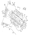
図1,2は、パッド43を配置部36に載せた状態で示す使い捨て着用物品20Aの斜視図と、パッド43を載せる以前の状態で示す図1の物品20Aの平面図とであり、図3,4は、図1の3−3線矢視断面図と、図1の4−4線矢視断面図とである。図1,2では、横方向を矢印L、縦方向を矢印Mで示し、厚み方向を矢印N(図1のみ)で示す。図2は、弾性部材40,41,54,57,60の収縮力に抗して物品20Aを縦横方向へ展開させた状態で示す。なお、表裏面シート26,27や防漏シート28の内面とは、コア29に対向する面をいい、それらシート26,27,28の外面とは、コア29に非対向の面をいう。また、パッド43を形成する表裏面シート44,45の内面とは、パッド43を形成するコア46に対向する面をいい、それらシート44,45の外面とは、コア46に非対向の面をいう。 1 and 2, a perspective view of a disposable wearing article 20A shown in a state carrying the pad 43 to the unit 36 is in the plane view of the article 20A of Fig. 1 showing a previous state Ru placing the pad 43, Fig. 3 and 4 are a sectional view taken along line 3-3 in FIG. 1 and a sectional view taken along line 4-4 in FIG. 1 and 2, the horizontal direction is indicated by an arrow L, the vertical direction is indicated by an arrow M, and the thickness direction is indicated by an arrow N (only in FIG. 1). FIG. 2 shows the article 20 </ b> A deployed in the vertical and horizontal directions against the contraction force of the elastic members 40, 41, 54, 57, and 60. The inner surfaces of the front and back sheets 26 and 27 and the leak-proof sheet 28 are surfaces facing the core 29, and the outer surfaces of the sheets 26, 27 and 28 are surfaces not facing the core 29. The inner surfaces of the front and back sheets 44 and 45 forming the pad 43 are surfaces facing the core 46 forming the pad 43, and the outer surfaces of the sheets 44 and 45 are surfaces not facing the core 46. Say.

物品20Aは、横方向へ延びる両端部21と、縦方向へ延びる両側部22とを有するとともに、縦方向に前胴周り域23および後胴周り域25と、それら胴周り域23,25の間に位置する股下域24とを有する。物品20Aは、肌当接側に位置する透液性表面シート26と、肌非当接側に位置する不透液性裏面シート27と、横方向に離間対向して縦方向へ延びる一対の不透液性防漏シート28と、表裏面シート26,27の間に介在してそれらシート26,27の内面に接合された所定厚みの吸液性コア29とから構成されている。股下域24の両側部22は、物品20Aの横方向内方へ向かって弧を画いている。物品20Aは、図2に示すように、その平面形状が砂時計型を呈する。物品20Aは、着用時に前後胴周り域23,25の両側部22を連結するオープン型の使い捨ておむつであり、排泄物を吸収保持するパッド43を表面シート26の外面に載せ、パッド43とともに着用する。 The article 20 </ b> A has both end portions 21 extending in the lateral direction and both side portions 22 extending in the vertical direction, and the front waistline region 23 and the back waistline region 25 in the vertical direction, and between these waistline regions 23, 25. And a crotch region 24 located at the bottom. The article 20A is composed of a liquid-permeable top sheet 26 located on the skin contact side, a liquid-impervious back sheet 27 located on the skin non-contact side, and a pair of non-extends extending in the vertical direction so as to face each other in the lateral direction. A liquid-permeable leak-proof sheet 28 and a liquid-absorbent core 29 having a predetermined thickness are provided between the front and back sheets 26 and 27 and joined to the inner surfaces of the sheets 26 and 27. Both side portions 22 of the crotch region 24 are arced inwardly in the lateral direction of the article 20A. As shown in FIG. 2, the planar shape of the article 20 </ b> A has an hourglass shape. The article 20 </ b> A is an open-type disposable diaper that connects both side portions 22 of the front and rear waist regions 23 and 25 when worn, and a pad 43 that absorbs and holds excrement is placed on the outer surface of the topsheet 26 and worn together with the pad 43. .

表面シート26は、親水性繊維不織布30から形成されている。裏面シート27は、通気不透液性プラスチックフィルム31と疎水性繊維不織布32とをラミネートした複合シートから形成されている。防漏シート28は、撥水処理が施された疎水性繊維不織布33から形成されている。コア29は、粒子状または繊維状の高吸収性ポリマーとフラッフパルプとの混合物、または、粒子状または繊維状の高吸収性ポリマーとフラッフパルプと熱可塑性合成樹脂繊維との混合物である。コア29は、所定の厚みに圧縮され、その剛性が表裏面シート26,27や防漏シート28のそれよりも高い。コア29は、それの型崩れを防止するため、全体がティッシュペーパー(図示せず)に包被されている。コア29は、前後胴周り域23,25と股下域24とに位置し、横方向へ延びる両端縁34と、縦方向へ延びる両側縁35とを有する。   The top sheet 26 is formed from a hydrophilic fiber nonwoven fabric 30. The back sheet 27 is formed of a composite sheet obtained by laminating a gas-impermeable liquid-impervious plastic film 31 and a hydrophobic fiber nonwoven fabric 32. The leak-proof sheet 28 is formed of a hydrophobic fiber nonwoven fabric 33 that has been subjected to water repellent treatment. The core 29 is a mixture of particulate or fibrous superabsorbent polymer and fluff pulp, or a mixture of particulate or fibrous superabsorbent polymer, fluff pulp and thermoplastic synthetic resin fiber. The core 29 is compressed to a predetermined thickness, and its rigidity is higher than that of the front and back sheets 26 and 27 and the leak-proof sheet 28. The core 29 is entirely covered with a tissue paper (not shown) in order to prevent the core 29 from being deformed. The core 29 is located in the front and rear waist regions 23 and 25 and the crotch region 24 and has both end edges 34 extending in the horizontal direction and both side edges 35 extending in the vertical direction.

前後胴周り域23,25と股下域24との横方向中央には、パッド43を載せるパッド配置部36が画成されている。配置部36は、その平面形状が縦方向へ長い矩形を呈し、股下域24から前胴周り域23の後半分と後胴周り域25の前半部とに延びている。配置部36は、コア29を除く表面シート26と裏面シート27とから形成され、コア29の内周壁37に囲まれている。配置部36は、前後胴周り域23,25に位置して横方向へ延びる両端縁38と、両端縁38間に位置して縦方向へ延びる両側縁39とを有する。配置部36は、両側縁38間の横方向の長さ寸法がパッド43の横方向のそれと同一またはパッド43の横方向のそれよりもわずかに大きく、両端縁39間の縦方向の長さ寸法がパッド43の縦方向のそれと同一またはパッド43の縦方向のそれよりもわずかに大きい。 The transverse center of the front and rear waist regions 23, 25 and the crotch region 24, the pad unit 36 of Ru carrying the pads 43 are defined. The placement portion 36 has a rectangular shape whose plan shape is long in the vertical direction, and extends from the crotch region 24 to the rear half of the front waistline region 23 and the front half of the back waistline region 25. The placement portion 36 is formed of a top sheet 26 and a back sheet 27 excluding the core 29, and is surrounded by an inner peripheral wall 37 of the core 29. The arrangement portion 36 has both end edges 38 that are located in the front and rear waist regions 23 and 25 and extend in the lateral direction, and both side edges 39 that are located between both end edges 38 and extend in the vertical direction. The arrangement portion 36 has a horizontal length dimension between the side edges 38 that is the same as or slightly larger than that of the pad 43 in the horizontal direction, and a vertical length dimension between the end edges 39. Is the same as that in the vertical direction of the pad 43 or slightly larger than that in the vertical direction of the pad 43.

表面シート26は、配置部36を囲むコア29の内周壁37に沿ってコア29の上面から下面に向かって延び、その内面がコア29の内周壁37に固着されている。配置部36では、表裏面シート26,27の内面どうしがコア29の下面の側で互いに固着されている。配置部36はコア29の下面の側に位置し、コア29の上面と配置部36との間にはコア29の厚み寸法に応じた段差が形成されている。配置部36には、縦方向へ直状に延びる複数条の第1伸縮性弾性部材40および第2伸縮性弾性部材41が収縮可能に取り付けられている。なお、配置部36の形状を図示の矩形に限定するものではなく、配置部36に楕円形や菱形、台形等の他の形状を採用することもできる。 The top sheet 26 extends from the upper surface of the core 29 toward the lower surface along the inner peripheral wall 37 of the core 29 surrounding the placement portion 36, and the inner surface thereof is fixed to the inner peripheral wall 37 of the core 29. In the arrangement portion 36, the inner surfaces of the front and back sheets 26 and 27 are fixed to each other on the lower surface side of the core 29. The placement portion 36 is located on the lower surface side of the core 29, and a step according to the thickness dimension of the core 29 is formed between the upper surface of the core 29 and the placement portion 36. A plurality of first elastic elastic members 40 and second elastic elastic members 41 extending straight in the vertical direction are attached to the arrangement portion 36 so as to be contractible. In addition, the shape of the arrangement | positioning part 36 is not limited to the rectangle of illustration, Other shapes, such as an ellipse, a rhombus, and a trapezoid, can also be employ | adopted for the arrangement | positioning part 36.

第1および第2弾性部材40,41は、配置部36の両側縁39の内側に配置され、横方向へ離間対向して並んでいる。第1および第2弾性部材40,41は、配置部36を縦断し、配置部36の両端縁38を越えて前胴周り域23の前半分と後胴周り域25の後半分とに達している。それら弾性部材40,41は、表面シート26と裏面シート27との間に介在し、縦方向へ所定の倍率に伸長させた状態でそれらシート26,27の内面に固着されている。第1および第2弾性部材40,41の縦方向両端部42は、前後胴周り域23,25に位置するコア29の下面に延びており、裏面シート27の内面とコア29の下面との間に介在し、裏面シート27の内面に固着されている。なお、それら弾性部材40,41は、糸条であるが、糸状の他に、帯状の弾性部材を使用することもできる。   The first and second elastic members 40 and 41 are arranged inside the side edges 39 of the arrangement portion 36 and are arranged to be spaced apart and opposed in the lateral direction. The first and second elastic members 40, 41 run vertically through the placement portion 36, reach the front half of the front waistline region 23 and the back half of the back waistline region 25 beyond both end edges 38 of the placement portion 36. Yes. The elastic members 40 and 41 are interposed between the top sheet 26 and the back sheet 27 and are fixed to the inner surfaces of the sheets 26 and 27 in a state where the elastic members 40 and 41 are stretched at a predetermined magnification in the vertical direction. Both longitudinal ends 42 of the first and second elastic members 40, 41 extend to the lower surface of the core 29 located in the front and rear waist regions 23, 25, and between the inner surface of the back sheet 27 and the lower surface of the core 29. And is fixed to the inner surface of the back sheet 27. The elastic members 40 and 41 are yarns, but a band-like elastic member can also be used in addition to the yarn shape.

パッド43は、肌当接側に位置する透液性表面シート44と、肌非当接側に位置する不透液性裏面シート45と、表裏面シート44,45の間に介在してそれらシート44,45の内面に接合された所定厚みの吸液性コア46とから形成されている。パッド43は、縦方向へ長い略矩形を呈し、横方向へ延びる両端部47と、縦方向へ延びる両側部48とを有する。パッド43を形成するコア46の厚み寸法は、物品20Aを形成するコア29のそれと略同一である。パッド43の両端部47と両側部48とでは、表裏面シート44,45が重なり合い、それらシート44,45の内面どうしが固着されている。表面シート44は親水性繊維不織布49から形成され、裏面シート27は疎水性繊維不織布50から形成されている。コア46は、物品20Aのそれと同一の混合物であって、その全体がティッシュペーパー(図示せず)に包被されている。なお、パッド43は、コア46と、コア46の全体を包被する透液性シートとから形成されていてもよい。   The pad 43 is interposed between the liquid-permeable surface sheet 44 positioned on the skin contact side, the liquid-impermeable back sheet 45 positioned on the skin non-contact side, and the front and back sheets 44 and 45. The liquid-absorbent core 46 has a predetermined thickness and is joined to the inner surfaces of 44 and 45. The pad 43 has a substantially rectangular shape that is long in the vertical direction, and has both end portions 47 that extend in the horizontal direction and both side portions 48 that extend in the vertical direction. The thickness dimension of the core 46 that forms the pad 43 is substantially the same as that of the core 29 that forms the article 20A. The front and back sheets 44 and 45 overlap each other at both end portions 47 and both side portions 48 of the pad 43, and the inner surfaces of the sheets 44 and 45 are fixed to each other. The top sheet 44 is formed from a hydrophilic fiber nonwoven fabric 49, and the back sheet 27 is formed from a hydrophobic fiber nonwoven fabric 50. The core 46 is the same mixture as that of the article 20A, and the whole is encased in a tissue paper (not shown). The pad 43 may be formed of a core 46 and a liquid-permeable sheet that covers the entire core 46.

防漏シート28は、表面シート26の外面の側に配置されている。防漏シート28は、両側部22に位置して縦方向へ延びる固定側部51と、固定側部51に並行して縦方向へ延びていて表面シート26の上方へ起立性向を有する自由部52と、両端部21に位置して物品20Aの横方向内方へ倒伏した固定両端部53とから形成されている。固定側部51と自由部52とは、物品20Aの両端部21間に延びている。自由部52の上方には、縦方向へ延びる伸縮性弾性部材54が収縮可能に取り付けられている。弾性部材54は、縦方向へ所定の倍率に伸長された状態で自由部52に固着されている。防漏シート28では、弾性部材54の収縮力によって自由部52が縦方向へ収縮し、自由部52が表面シート26の上方へ起立して排泄物に対する障壁を形成する。   The leak-proof sheet 28 is disposed on the outer surface side of the top sheet 26. The leak-proof sheet 28 is positioned on the both side portions 22 and extends in the vertical direction, and the free portion 52 extends in the vertical direction in parallel with the fixed side portion 51 and has an upright orientation above the topsheet 26. And fixed both end portions 53 located at both end portions 21 and lying inward in the lateral direction of the article 20A. The fixed side portion 51 and the free portion 52 extend between both end portions 21 of the article 20A. A stretchable elastic member 54 extending in the vertical direction is attached above the free portion 52 so as to be shrinkable. The elastic member 54 is fixed to the free portion 52 in a state where the elastic member 54 is extended in the vertical direction at a predetermined magnification. In the leak-proof sheet 28, the free portion 52 contracts in the vertical direction by the contraction force of the elastic member 54, and the free portion 52 stands up above the top sheet 26 to form a barrier against excrement.

両端部21は、コア29の端縁34から縦方向外方へ延びる表裏面シート26,27の端部55,56と防漏シート28の固定端部53とから形成されている。両端部21では、表裏面シート26,27の端部55,56と防漏シート28の端部53とが重なり合い、表裏面シート26,27の内面どうしが固着され、表面シート26の外面と防漏シート28の内面とが固着されている。端部21には、コア29の端縁34の縦方向外方に位置して横方向へ延びる複数条の胴周り用弾性部材57が収縮可能に取り付けられている。胴周り用弾性部材57は、表面シート26の端部55と裏面シート27の端部56と間に介在し、横方向へ所定の倍率に伸長させた状態でそれらシート26,27の内面に固着されている。   Both end portions 21 are formed from end portions 55 and 56 of front and back sheets 26 and 27 extending from the end edge 34 of the core 29 in the longitudinal direction outward and a fixed end portion 53 of the leak-proof sheet 28. At both end portions 21, the end portions 55, 56 of the front and back sheets 26, 27 overlap the end portion 53 of the leak-proof sheet 28, and the inner surfaces of the front and back sheets 26, 27 are fixed to each other. The inner surface of the leakage sheet 28 is fixed. A plurality of waistline elastic members 57 are attached to the end portion 21 so as to be retractable, being positioned outwardly in the longitudinal direction of the edge 34 of the core 29 and extending in the lateral direction. The waist elastic member 57 is interposed between the end portion 55 of the top sheet 26 and the end portion 56 of the back sheet 27, and is fixed to the inner surfaces of the sheets 26 and 27 in a state of being stretched at a predetermined magnification in the lateral direction. Has been.

両側部22は、コア29の側縁35から横方向外方へ延びる表裏面シート26,27の側部58,59と防漏シート28の固定側部51とから形成されている。両側部22では、表面シート26の側部58がコア29の側縁35から横方向外方へわずかに延び、側部58からさらに横方向外方へ裏面シート27の側部59と防漏シート28の側部51とが延びている。両側部22では、表裏面シート26,27の側部58,59と防漏シート28の側部51とが重なり合い、表裏面シート26,27の内面どうしが固着され、表裏面シート26,27の内外面と防漏シート28の内面とが固着されている。両側部22には、コア29の側縁35の横方向外方に位置して縦方向へ延びる複数条の脚周り用弾性部材60が収縮可能に取り付けられている。脚周り用弾性部材60は、裏面シート27の側部59と防漏シート28の固定側部51との間に介在し、横方向へ所定の倍率に伸長させた状態でそれらシート27,28の内面に固着されている。   Both side portions 22 are formed by side portions 58 and 59 of front and back sheets 26 and 27 extending laterally outward from the side edge 35 of the core 29 and a fixed side portion 51 of the leak-proof sheet 28. In both side portions 22, the side portions 58 of the top sheet 26 slightly extend laterally outward from the side edges 35 of the core 29, and further laterally outward from the side portions 58 to the side portions 59 of the back sheet 27 and the leak-proof sheet. 28 side portions 51 extend. In the both side portions 22, the side portions 58 and 59 of the front and back sheets 26 and 27 and the side portion 51 of the leak-proof sheet 28 are overlapped, and the inner surfaces of the front and back sheets 26 and 27 are fixed to each other. The inner and outer surfaces and the inner surface of the leak-proof sheet 28 are fixed. A plurality of leg-around elastic members 60 extending in the vertical direction and extending in the vertical direction are attached to the both side portions 22 so as to be shrinkable. The leg-around elastic member 60 is interposed between the side portion 59 of the back sheet 27 and the fixed side portion 51 of the leak-proof sheet 28, and extends in a lateral direction at a predetermined magnification. It is fixed to the inner surface.

後胴周り域25の両側部22には、繊維不織布から形成された可撓性のテープファスナ61が取り付けられている。テープファスナ61は、横方向へ延びる固定端部62と自由端部63とを有する。固定端部62は、裏面シート27の側部59と防漏シート28の固定側部51との間に介在し、それらシート27,28の内面に固着されている。自由端部63には、フック部材64が取り付けられている。なお、自由端部63には、フック部材64ではなく、剥離紙に被覆された粘着剤が塗布されていてもよい。   A flexible tape fastener 61 formed of a fiber nonwoven fabric is attached to both side portions 22 of the rear waistline region 25. The tape fastener 61 has a fixed end 62 and a free end 63 that extend in the lateral direction. The fixed end portion 62 is interposed between the side portion 59 of the back sheet 27 and the fixed side portion 51 of the leak-proof sheet 28, and is fixed to the inner surfaces of the sheets 27 and 28. A hook member 64 is attached to the free end 63. The free end 63 may be coated with an adhesive coated with release paper instead of the hook member 64.

前胴周り域23には、テープファスナ61の自由端部63を着脱可能に止着する可撓性のターゲットテープ65が取り付けられている。ターゲットテープ65は、横方向へ長い矩形を呈し、プラスチックフィルム66と、フィルム66に取り付けられたループ部材67とから形成されている(図5参照)。ターゲットテープ65は、それを形成するフィルム66が裏面シート27の外面に固着されている。テープファスナ61の自由端部63に粘着剤を塗布する場合は、ターゲットテープ65にプラスチックフィルムが使用される。   A flexible target tape 65 for attaching the free end 63 of the tape fastener 61 detachably is attached to the front waistline region 23. The target tape 65 has a rectangular shape that is long in the lateral direction, and is formed of a plastic film 66 and a loop member 67 attached to the film 66 (see FIG. 5). The target tape 65 has a film 66 forming it fixed to the outer surface of the back sheet 27. When an adhesive is applied to the free end 63 of the tape fastener 61, a plastic film is used for the target tape 65.

図5,6は、着用状態で示す図1の物品20Aの斜視図と、図5の6−6線矢視断面図とである。図6では、着用者を二点鎖線で示す。この物品20Aを着用する手順は、以下のとおりである。表面シート26の外面とパッド43の裏面シート45の外面とが当接するように、配置部36にパッド43を載せる。パッド43を配置部36に載せると、パッド43の両端部47が配置部36の両端縁38の内側に位置し、パッド43の両側部48が配置部36の両側縁39の内側に位置する。パッド43を配置部36に載せた後、着用者の臀部74を後胴周り域25に載せ、股下域24を折り曲げて前胴周り域23を腹部72の上に載せる。次に、後胴周り域25の両側部22を前胴周り域23の両側部22の外側に重ね合わせ、フック部材64を介してテープファスナ61の自由端部63をターゲットテープ65に止着して前胴周り域23と後胴周り域25とを連結する。前後胴周り域23,25が連結された物品20Aには、胴周り開口68とその下方に一対の脚周り開口69とが形成される。物品20Aは、前胴周り域23が着用者の腹部72に当接し、股下域24が股間部73に当接するとともに、後胴周り域25が臀部74と背部75とに当接する。物品20Aの着用中に排泄された排泄物は、パッド43の表面シート44を透過してコア46に吸収される。 5 and 6 are a perspective view of the article 20A of FIG. 1 shown in a worn state and a cross-sectional view taken along line 6-6 in FIG. In FIG. 6, a wearer is shown with a dashed-two dotted line. The procedure for wearing the article 20A is as follows. As the outer surface of the backsheet 45 of the outer surface and the pad 43 of the topsheet 26 is in contact, Ru place the pad 43 to the unit 36. When Ru Place the pad 43 to the unit 36, both end portions 47 of the pad 43 is located inside the end edges 38 of the unit 36, both side portions 48 of the pad 43 is located inside the side edges 39 of the unit 36 . After placing the pads 43 to the unit 36, placing the buttocks 74 of the wearer in the rear waist region 25, Ru place the front waist region 23 on the abdomen 72 by folding the crotch region 24. Next, both side portions 22 of the rear waist region 25 are overlapped on the outside of both side portions 22 of the front waist region 23, and the free end 63 of the tape fastener 61 is fixed to the target tape 65 via the hook member 64. The front waistline region 23 and the back waistline region 25 are connected. In the article 20A in which the front and rear waist regions 23 and 25 are coupled, a waist opening 68 and a pair of leg openings 69 are formed below the waist opening 68. In the article 20 </ b> A, the front waist region 23 abuts the wearer's abdomen 72, the crotch region 24 abuts the crotch portion 73, and the back waist region 25 abuts the buttocks 74 and the back 75. Excretion excreted while wearing the article 20 </ b> A passes through the top sheet 44 of the pad 43 and is absorbed by the core 46.

物品20Aは、それを着用すると、第1および第2弾性部材40,41が着用者の股間部73でU字状に湾曲し、それら弾性部材40,41が股間部73から着用者の腹部72と臀部74とに向かって延びる。物品20Aは、第1および第2弾性部材40,41の収縮力が配置部36の略全体に作用し、配置部36が着用者の股間部73に向かって吊り上げられるとともに、配置部36に載せたパッド43全体が物品20Aの厚み方向上方へ持ち上げられる。物品20Aは、弾性部材40,41の収縮力によって持ち上げられたパッド43の肌当接面が表面シート26の上方に位置するので、パッド43が着用者の肌に密着し、パッド43と着用者の肌との間に隙間が生じることはなく、排泄物をパッド43に確実に吸収保持させることができる。物品20Aでは、パッド43の両端部47と両側部48とから漏れた排泄物が物品20Aの表面シート26を透過して配置部36を囲むコア29に吸収されるので、排泄物が物品20Aの外側に漏れてしまうことはない。 When the article 20A is worn, the first and second elastic members 40 and 41 are curved in a U shape at the crotch portion 73 of the wearer, and the elastic members 40 and 41 extend from the crotch portion 73 to the abdomen 72 of the wearer. And extending toward the flange 74. In the article 20A, the contraction force of the first and second elastic members 40 and 41 acts on substantially the entire placement portion 36, and the placement portion 36 is lifted toward the wearer's crotch portion 73 and placed on the placement portion 36. The entire pad 43 is lifted upward in the thickness direction of the article 20A. In the article 20A, since the skin contact surface of the pad 43 lifted by the contraction force of the elastic members 40 and 41 is located above the top sheet 26, the pad 43 is in close contact with the wearer's skin, and the pad 43 and the wearer There is no gap between the skin and the excrement can be reliably absorbed and retained by the pad 43. In the article 20A, the excrement leaking from the both ends 47 and both sides 48 of the pad 43 passes through the surface sheet 26 of the article 20A and is absorbed by the core 29 surrounding the arrangement part 36, so the excrement is absorbed in the article 20A. There is no leakage outside.

物品20Aは、弾性部材40,41の収縮力によってパッド43が物品20Aの厚み方向上方へ持ち上げられるので、パッド43のコア46の厚み寸法を物品20Aのコア29の厚み寸法よりも小さくしたとしても、パッド43を着用者の肌に密着させることができ、パッド43にコア29よりも厚み寸法の小さいコア46を使用することができ、パッド43の嵩張りを防ぐことができる。物品20Aは、第1および第2弾性部材40,41の縦方向両端部42が前後胴周り域23,25に位置するコア29の下面に延びているので、それら弾性部材40,41の収縮力によって前後胴周り域23,25に位置するコア29を着用者の肌に押し当てることができる。   In the article 20A, the pad 43 is lifted upward in the thickness direction of the article 20A by the contraction force of the elastic members 40 and 41. Therefore, even if the thickness dimension of the core 46 of the pad 43 is smaller than the thickness dimension of the core 29 of the article 20A. The pad 43 can be brought into close contact with the skin of the wearer, and the core 46 having a thickness smaller than that of the core 29 can be used for the pad 43, and the pad 43 can be prevented from being bulky. In the article 20A, the longitudinal end portions 42 of the first and second elastic members 40, 41 extend to the lower surface of the core 29 located in the front and rear waist regions 23, 25. Thus, the core 29 located in the front and rear waist regions 23 and 25 can be pressed against the skin of the wearer.

物品20Aは、コア29の上面と配置部36との間に物品20Aの厚み方向へ段差が生じ、パッド43の両端部47と両側部48とがコア29の内周壁37の内側に位置しているので、コア29の内周壁37によってパッド43の縦横方向へのずれ動きが阻止され、物品20Aの着用中におけるパッド43の不用意なずれ動きを防ぐことができる。また、物品20Aは、パッド43に着用者の体圧がかかると、配置部36を物品20Aの厚み方向下方へ押し下げる力がパッド43から配置部36に作用し、配置部36が弾性部材40,41の収縮力に抗して物品20Aの厚み方向下方へ凹み、それにともなってパッド43が物品20Aの厚み方向下方へ下がるので、パッド43が嵩張ることはなく、着用した物品20Aに対する違和感がない。   The article 20 </ b> A has a step in the thickness direction of the article 20 </ b> A between the upper surface of the core 29 and the arrangement portion 36, and both end portions 47 and both side portions 48 of the pad 43 are positioned inside the inner peripheral wall 37 of the core 29. Therefore, the inner wall 37 of the core 29 prevents the pad 43 from moving in the vertical and horizontal directions, and the pad 43 can be prevented from being moved unintentionally while the article 20A is worn. When the wearer's body pressure is applied to the pad 43, the article 20 </ b> A exerts a force that pushes the arrangement part 36 downward in the thickness direction of the article 20 </ b> A from the pad 43 to the arrangement part 36. The article 43 is recessed downward in the thickness direction of the article 20A against the contraction force of the article 41, and the pad 43 is lowered downward in the thickness direction of the article 20A. Accordingly, the pad 43 is not bulky and there is no sense of incongruity with the worn article 20A.

物品20Aでは、配置部36の剛性値が0.1〜2.0mN・cmの範囲、好ましくは、0.8〜1.5mN・cmの範囲にある。配置部36の剛性値が0.1mN・cm未満では、弾性部材40,41の伸長応力にもよるが、弾性部材40,41の収縮力によって配置部36が縦方向へ必要以上に縮み、物品20Aの縦寸法を縮めてしまう場合がある。配置部36の剛性値が2.0mN・cmを超過すると、弾性部材40,41の収縮力が配置部36の剛性によって妨げられ、弾性部材40,41の収縮力を利用することができず、配置部36に載せたパッド43を物品20Aの厚み方向上方へ持ち上げることができない。なお、配置部36の剛性値は、ガーレ法(JIS L 1096−01−8.20.1)に準拠して測定した。その測定方法は、以下のとおりである。
(1)物品20Aから配置部36を裁断し、縦寸法25.0mm×横寸法38.0mmの測定用サンプルを作成する。剛性値の測定には、ガーレ柔軟度試験機を使用する。
(2)サンプルの縦方向一端部を試験機のチャックに挟み、サンプルの縦方向他端部を試験機の振り子にかけ、試験機の目盛りが3〜6の間になるように補助重りを取り付ける。試験機のスイッチを入れ、サンプルから振り子の回転ロッドが離れる瞬間の目盛りを読み、第1剛性値を測定する。次に、サンプルの縦方向他端部を試験機のチャックに挟み、サンプルの縦方向一端部を試験機の振り子にかけ、試験機の目盛りが3〜6の間になるように補助重りを取り付ける。試験機のスイッチを入れ、サンプルから振り子の回転ロッドが離れる瞬間の目盛りを読み、第2剛性値を測定する。測定した第1および第2剛性値の平均をサンプルの剛性値とする。測定したサンプルの剛性値は0.1〜2.0mN・cmであり、サンプルの剛性値を配置部36の剛性値とする。
In the article 20A, the rigidity value of the arrangement portion 36 is in the range of 0.1 to 2.0 mN · cm, preferably in the range of 0.8 to 1.5 mN · cm. If the rigidity value of the arrangement part 36 is less than 0.1 mN · cm, the arrangement part 36 contracts in the longitudinal direction more than necessary due to the contraction force of the elastic members 40 and 41, depending on the elongation stress of the elastic members 40 and 41, and the article. The vertical dimension of 20A may be reduced. When the rigidity value of the arrangement part 36 exceeds 2.0 mN · cm, the contraction force of the elastic members 40 and 41 is hindered by the rigidity of the arrangement part 36, and the contraction force of the elastic members 40 and 41 cannot be used. The pad 43 placed on the placement portion 36 cannot be lifted upward in the thickness direction of the article 20A. In addition, the rigidity value of the arrangement | positioning part 36 was measured based on the Gurley method (JISL1096-01-8.20.1). The measurement method is as follows.
(1) The arrangement portion 36 is cut from the article 20A, and a measurement sample having a vertical dimension of 25.0 mm and a horizontal dimension of 38.0 mm is created. A Gurley flexibility tester is used to measure the stiffness value.
(2) One end of the sample in the vertical direction is sandwiched between chucks of the tester, the other end of the sample in the vertical direction is placed on the pendulum of the tester, and an auxiliary weight is attached so that the scale of the tester is between 3 and 6. Switch on the tester, read the scale at the moment when the rotating rod of the pendulum leaves the sample, and measure the first stiffness value. Next, the other end in the vertical direction of the sample is sandwiched between chucks of the tester, one end in the vertical direction of the sample is placed on the pendulum of the tester, and an auxiliary weight is attached so that the scale of the tester is between 3 and 6. Turn on the tester, read the scale at the moment when the rotating rod of the pendulum leaves the sample, and measure the second stiffness value. The average of the measured first and second stiffness values is taken as the sample stiffness value. The measured stiffness value of the sample is 0.1 to 2.0 mN · cm, and the stiffness value of the sample is taken as the stiffness value of the placement portion 36.

物品20Aでは、第1および第2弾性部材40,41の伸長応力が0.1〜4.0Nの範囲にある。弾性部材40,41の伸長応力は、弾性部材1本の伸長応力である。弾性部材40,41の伸長応力が0.1N未満では、配置部36の剛性値にもよるが、弾性部材40,41の収縮力が配置部36に作用せず、弾性部材40,41の収縮力を利用して配置部36に載せたパッド43を物品20Aの厚み方向上方へ持ち上げることができない。弾性部材40,41の伸長応力が4.0Nを超過すると、弾性部材40,41の収縮力によって配置部36が縦方向へ必要以上に縮み、物品20Aの縦寸法を縮めてしまう場合がある。なお、弾性部材40,41の伸長応力は、以下の方法で測定した。
(1)物品20Aに使用した弾性部材40,41と同一のそれを測定用サンプル(1本)として用意する。伸長応力測定には、島津製作所社製の引張り試験機を使用した。
(2)サンプルの縦方向両端部を引張り試験機のチャックで挟み(チャックによるサンプルの挟み寸法:約10mm、サンプルのチャック間寸法:約100mm)、100mm/minの速度でサンプルを縦方向へ引っ張り、サンプルを300%まで伸長させた後、伸長状態を解除する。再度、試験機を介して100mm/minの速度でサンプルを縦方向へ引っ張り、サンプルを200%まで伸長させ、そのときの試験機にかかる力を測定する。サンプルの伸長応力は0.1〜4.0Nであり、サンプルの伸長応力を弾性部材40,41の1本の伸長応力とする。ここで、サンプルを200%まで伸長させるとは、たとえば、サンプルのチャック間寸法が100mmの場合、サンプルを100mmに2.0を乗じた値である約200mmまで伸ばすことである。
In the article 20A, the elongation stress of the first and second elastic members 40 and 41 is in the range of 0.1 to 4.0 N. The extension stress of the elastic members 40 and 41 is the extension stress of one elastic member. When the elongation stress of the elastic members 40 and 41 is less than 0.1 N, the contraction force of the elastic members 40 and 41 does not act on the arrangement portion 36 and the elastic members 40 and 41 contract depending on the rigidity value of the arrangement portion 36. The pad 43 placed on the placement portion 36 cannot be lifted upward in the thickness direction of the article 20A using force. If the elongation stress of the elastic members 40 and 41 exceeds 4.0 N, the arrangement portion 36 may be unnecessarily contracted in the vertical direction due to the contraction force of the elastic members 40 and 41, and the vertical dimension of the article 20A may be reduced. In addition, the elongation stress of the elastic members 40 and 41 was measured by the following method.
(1) Prepare the same elastic member 40, 41 used for the article 20A as a measurement sample (one). For the tensile stress measurement, a tensile tester manufactured by Shimadzu Corporation was used.
(2) Both longitudinal ends of the sample are clamped by a chuck of a tensile tester (sample clamping dimension of the chuck: about 10 mm, dimension between the chucks of the sample: about 100 mm), and the sample is pulled longitudinally at a speed of 100 mm / min. After extending the sample to 300%, the extended state is released. Again, the sample is pulled in the longitudinal direction through the testing machine at a speed of 100 mm / min, the sample is stretched to 200%, and the force applied to the testing machine at that time is measured. The elongation stress of the sample is 0.1 to 4.0 N, and the elongation stress of the sample is one elongation stress of the elastic members 40 and 41. Here, elongating the sample to 200% means, for example, that when the dimension between chucks of the sample is 100 mm, the sample is extended to about 200 mm, which is a value obtained by multiplying 100 mm by 2.0.

図7,8は、パッド43を配置部36に載せた状態で示す他の一例の使い捨て着用物品20Bの斜視図と、パッド43を載せる以前の状態で示す図7の物品20Bの平面図とであり、図9,10は、図7の9−9線矢視断面図と、図7の10−10線矢視断面図とである。図7,8では、横方向を矢印L、縦方向を矢印Mで示し、厚み方向を矢印N(図7のみ)で示す。図8は、弾性部材40,41,54,57,60の収縮力に抗して物品20Bを縦横方向へ展開させた状態で示す。 7 and 8, a perspective view of another example of the disposable wearing article 20B shown in a state carrying the pad 43 to the unit 36, and a plan view of the article 20B of Fig. 7 showing in a state before the Ru placing the pad 43 9 and 10 are a sectional view taken along line 9-9 in FIG. 7 and a sectional view taken along line 10-10 in FIG. 7 and 8, the horizontal direction is indicated by an arrow L, the vertical direction is indicated by an arrow M, and the thickness direction is indicated by an arrow N (only in FIG. 7). FIG. 8 shows the article 20 </ b> B deployed in the vertical and horizontal directions against the contraction force of the elastic members 40, 41, 54, 57, and 60.

物品20Bは、横方向へ延びる両端部21と、縦方向へ延びる両側部22とを有するとともに、縦方向に前胴周り域23および後胴周り域25と、それら胴周り域23,25の間に位置する股下域24とを有する。物品20Bは、透液性表面シート26および不透液性裏面シート27と、縦方向へ延びる一対の不透液性防漏シート28と、表裏面シート26,27の間に介在してそれらシート26,27の内面に接合された吸液性コア29とから構成されている。物品20Bは、図1のそれと同様のオープン型の使い捨ておむつであり、排泄物を吸収保持するパッド43を表面シート26の外面に載せ、パッド43とともに着用する。 The article 20B has both end portions 21 extending in the horizontal direction and both side portions 22 extending in the vertical direction, and the front waist region 23 and the back waist region 25 in the vertical direction, and between the waist regions 23, 25. And a crotch region 24 located at the bottom. The article 20B is interposed between a liquid-permeable top sheet 26 and a liquid-impervious back sheet 27, a pair of liquid-impervious leak-proof sheets 28 extending in the vertical direction, and the front and back sheets 26 and 27. The liquid-absorbent core 29 is joined to the inner surfaces of 26 and 27. The article 20 </ b> B is an open-type disposable diaper similar to that of FIG. 1, and a pad 43 that absorbs and holds excrement is placed on the outer surface of the top sheet 26 and worn together with the pad 43.

表面シート26は、親水性繊維不織布30から形成されている。裏面シート27は、図1のそれと同一の複合シートから形成されている。防漏シート28は、撥水処理が施された疎水性繊維不織布33から形成されている。コア29は、図1のそれと同一の混合物であり、前後胴周り域23,25と股下域24とに位置し、横方向へ延びる両端縁34と、縦方向へ延びる両側縁35とを有する。パッド43は、図1のそれと同一であり、透液性表面シート44および不透液性裏面シート45と、それらシート44,45の間に介在する所定厚みの吸液性コア46とから形成され、横方向へ延びる両端部47と、縦方向へ延びる両側部48とを有する。   The top sheet 26 is formed from a hydrophilic fiber nonwoven fabric 30. The back sheet 27 is formed from the same composite sheet as that of FIG. The leak-proof sheet 28 is formed of a hydrophobic fiber nonwoven fabric 33 that has been subjected to water repellent treatment. The core 29 is the same mixture as that of FIG. 1 and is located in the front and rear waist regions 23 and 25 and the crotch region 24 and has both side edges 34 extending in the lateral direction and both side edges 35 extending in the vertical direction. The pad 43 is the same as that shown in FIG. 1, and is formed of a liquid-permeable top sheet 44 and a liquid-impervious back sheet 45, and a liquid-absorbent core 46 having a predetermined thickness interposed between the sheets 44 and 45. , Both end portions 47 extending in the horizontal direction and both side portions 48 extending in the vertical direction.

前胴周り域23と股下域24との横方向中央には、パッド43を載せるパッド配置部36が画成されている。配置部36は、縦方向へ長い略矩形を呈し、股下域24から前胴周り域23の後半分に延びている。配置部36は、コア29を除く表面シート26と裏面シート27とから形成され、コア29の内周壁37に囲まれている。配置部36は、横方向へ延びる両端縁38と、縦方向へ延びる両側縁39とを有し、両側縁39間の横方向の長さ寸法がパッド43の横方向のそれと同一またはパッド43の横方向のそれよりも大きく、両端縁38間の縦方向の長さ寸法がパッド43の縦方向のそれよりも小さい。 The transverse center of the front waist region 23 and the crotch region 24, the pad unit 36 of Ru carrying the pads 43 are defined. The arrangement portion 36 has a substantially rectangular shape that is long in the vertical direction, and extends from the crotch region 24 to the rear half of the front waistline region 23. The placement portion 36 is formed of a top sheet 26 and a back sheet 27 excluding the core 29, and is surrounded by an inner peripheral wall 37 of the core 29. The arrangement portion 36 has both side edges 38 extending in the lateral direction and both side edges 39 extending in the vertical direction, and the lateral length between the side edges 39 is the same as that in the lateral direction of the pad 43 or the pad 43. It is larger than that in the horizontal direction, and the length in the vertical direction between both end edges 38 is smaller than that in the vertical direction of the pad 43.

表面シート26は、コア29の内周壁37に沿ってコア29の上面から下面に向かって延び、その内面がコア29の内周壁37に固着されている。配置部36では、表裏面シート26,27の内面どうしがコア29の下面の側で互いに固着されている。配置部36はコア29の下面の側に位置し、コア29の上面と配置部36との間にはコア29の厚み寸法に応じた段差が形成されている。配置部36には、物品20Bの横方向内方へ弧を画いて縦方向へ延びる複数条の第1および第2伸縮性弾性部材40,41が収縮可能に取り付けられている。 The top sheet 26 extends from the upper surface of the core 29 toward the lower surface along the inner peripheral wall 37 of the core 29, and the inner surface thereof is fixed to the inner peripheral wall 37 of the core 29. In the arrangement portion 36, the inner surfaces of the front and back sheets 26 and 27 are fixed to each other on the lower surface side of the core 29. The placement portion 36 is located on the lower surface side of the core 29, and a step according to the thickness dimension of the core 29 is formed between the upper surface of the core 29 and the placement portion 36. A plurality of first and second stretchable elastic members 40 and 41 extending in the vertical direction by forming an arc inwardly in the horizontal direction of the article 20B are attached to the arrangement portion 36 so as to be contractible.

第1および第2弾性部材40,41は、配置部36の両側縁38の内側に配置され、横方向へ離間対向して並んでいる。第1および第2弾性部材40,41の横方向の離間寸法は、配置部36の縦方向中央で最小となっている。それら弾性部材40,41は、配置部36を縦断し、配置部36の両端縁39を越えて前胴周り域23の前半分と後胴周り域25とに達している。配置部36に延びるそれら弾性部材40,41は、表面シート26と裏面シート27との間に介在し、それらシートの内面に固着されている。それら弾性部材40,41の縦方向両端部42は、前後胴周り域23,25に位置するコア29の下面に延びており、裏面シート27の内面とコア29の下面との間に介在し、裏面シート27の内面に固着されている。   The first and second elastic members 40 and 41 are arranged inside the side edges 38 of the arrangement portion 36 and are arranged to be spaced apart and opposed in the lateral direction. The lateral separation dimension of the first and second elastic members 40 and 41 is the smallest at the center in the longitudinal direction of the arrangement portion 36. These elastic members 40, 41 run vertically through the placement portion 36, reach the front half of the front waistline region 23 and the back waistline region 25 beyond both end edges 39 of the placement portion 36. The elastic members 40 and 41 extending to the placement portion 36 are interposed between the top sheet 26 and the back sheet 27 and are fixed to the inner surfaces of the sheets. The longitudinal end portions 42 of the elastic members 40 and 41 extend to the lower surface of the core 29 located in the front and rear waist regions 23 and 25, and are interposed between the inner surface of the back sheet 27 and the lower surface of the core 29, It is fixed to the inner surface of the back sheet 27.

防漏シート28は、両側部21に位置して縦方向へ延びる固定側部51と、表面シート26の上方へ起立性向を有して縦方向へ延びる自由部52と、両端部22に位置して物品20Bの横方向内方へ倒伏した固定両端部53とから形成されている。自由部52の上方には、縦方向へ延びる伸縮性弾性部材54が収縮可能に取り付けられている。防漏シート28では、弾性部材54の収縮力によって表面シート26の上方へ起立した自由部52が排泄物に対する障壁を形成する。   The leak-proof sheet 28 is positioned at both side portions 21, a fixed side portion 51 that extends in the vertical direction, a free portion 52 that extends in the vertical direction with an upright orientation above the topsheet 26, and both end portions 22. And both fixed end portions 53 lying inward in the lateral direction of the article 20B. A stretchable elastic member 54 extending in the vertical direction is attached above the free portion 52 so as to be shrinkable. In the leak-proof sheet 28, the free portion 52 erected above the top sheet 26 by the contraction force of the elastic member 54 forms a barrier against excrement.

両端部21は、コア29の端縁34から縦方向外方へ延びる表裏面シート26,27の端部55,56と防漏シート28の固定端部53とから形成されている。両端部21では、端部55,56と固定端部53とが重なり合い、表裏面シート26,27の内面どうしが固着され、表面シート26の外面と防漏シート28の内面とが固着されている。端部21には、横方向へ延びる複数条の胴周り用弾性部材57が収縮可能に取り付けられている。   Both end portions 21 are formed from end portions 55 and 56 of front and back sheets 26 and 27 extending from the end edge 34 of the core 29 in the longitudinal direction outward and a fixed end portion 53 of the leak-proof sheet 28. At both end portions 21, the end portions 55 and 56 and the fixed end portion 53 overlap, the inner surfaces of the front and back sheets 26 and 27 are fixed, and the outer surface of the top sheet 26 and the inner surface of the leak-proof sheet 28 are fixed. . A plurality of waist elastic members 57 extending in the lateral direction are attached to the end portion 21 so as to be shrinkable.

両側部22は、コア29の側縁35から横方向外方へ延びる表裏面シート26,27の側部58,59と防漏シート28の固定側部51とから形成されている。両側部22では、側部58がコア29の側縁35から横方向外方へわずかに延び、側部58からさらに横方向外方へ側部59と側部51とが延びている。両側部22では、側部51,58,59が重なり合い、表裏面シート26,27の内面どうしが固着され、表裏面シート26,27の内外面と防漏シート28の内面とが固着されている。両側部22には、縦方向へ延びる複数条の脚周り用弾性部材60が収縮可能に取り付けられている。   Both side portions 22 are formed by side portions 58 and 59 of front and back sheets 26 and 27 extending laterally outward from the side edge 35 of the core 29 and a fixed side portion 51 of the leak-proof sheet 28. In the both side portions 22, the side portions 58 slightly extend laterally outward from the side edges 35 of the core 29, and the side portions 59 and 51 extend further laterally outward from the side portions 58. In both side portions 22, the side portions 51, 58, and 59 are overlapped, the inner surfaces of the front and back sheets 26 and 27 are fixed, and the inner and outer surfaces of the front and back sheets 26 and 27 and the inner surface of the leak-proof sheet 28 are fixed. . A plurality of leg-around elastic members 60 extending in the vertical direction are attached to both side portions 22 so as to be shrinkable.

後胴周り域25の両側部22には、繊維不織布から形成された可撓性のテープファスナ61が取り付けられている。テープファスナ61の固定端部62は、裏面シート27の側部59と防漏シート28の固定側部51との間に介在し、それらシート27,28の内面に固着されている。テープファスナ61の自由端部63の内面には、フック部材64が取り付けられている。前胴周り域23には、テープファスナ61の自由端部63を着脱可能に止着する可撓性のターゲットテープ65が取り付けられている。ターゲットテープ65は、プラスチックフィルム66と、フィルム66に取り付けられたループ部材67とから形成されている(図11参照)。   A flexible tape fastener 61 formed of a fiber nonwoven fabric is attached to both side portions 22 of the rear waistline region 25. The fixed end portion 62 of the tape fastener 61 is interposed between the side portion 59 of the back sheet 27 and the fixed side portion 51 of the leak-proof sheet 28 and is fixed to the inner surfaces of the sheets 27 and 28. A hook member 64 is attached to the inner surface of the free end portion 63 of the tape fastener 61. A flexible target tape 65 for attaching the free end 63 of the tape fastener 61 detachably is attached to the front waistline region 23. The target tape 65 is formed of a plastic film 66 and a loop member 67 attached to the film 66 (see FIG. 11).

図11,12は、着用状態で示す図7の物品20Bの斜視図と、図11の12−12線矢視断面図とである。図12では、着用者を二点鎖線で示す。この物品20Bを着用する手順は、図1のそれと同様であり、その説明は省略する。ただし、この物品20Bでは、パッド43を配置部36に載せると、パッド43の両端部47が表面シート26を挟んで前後胴周り域23,25に延びるコア29の上方に重なり、パッド43の両側部48が配置部36の両側縁39の内側に位置する。 11 and 12 are a perspective view of the article 20B of FIG. 7 shown in a worn state and a cross-sectional view taken along line 12-12 of FIG. In FIG. 12, a wearer is shown with a dashed-two dotted line. The procedure for wearing this article 20B is the same as that of FIG. 1, and the description thereof is omitted. However, in this article 20B, the Ru place the pad 43 to the unit 36, the overlap above the core 29 extending in the front and rear waist regions 23, 25 at both end portions 47 of the pad 43 across the topsheet 26, the pad 43 Both side portions 48 are located inside the side edges 39 of the arrangement portion 36.

物品20Bは、それを着用すると、第1および第2弾性部材40,41が着用者の股間部73でU字状に湾曲し、それら弾性部材40,41が股間部73から着用者の腹部72と臀部74とに向かって延びる。物品20Bは、第1および第2弾性部材40,41の収縮力が配置部36の略全体に作用し、それら弾性部材40,41の収縮力によって配置部36全体が着用者の股間部73に向かって吊り上げられるとともに、配置部36に載せたパッド43全体が物品20Bの厚み方向上方へ持ち上げられるので、パッド43全体を着用者の肌に密着させることができる。物品20Bは、弾性部材40,41の収縮力によって持ち上げられたパッド43の肌当接面が表面シート26の上方に位置するので、パッド43が着用者の肌に密着し、パッド43と着用者の肌との間に隙間が生じることはなく、排泄物をパッド43に確実に吸収保持させることができる。物品20Bは、第1および第2弾性部材40,41が配置部36において物品20Bの横方向内方へ弧を画いているので、それら弾性部材40,41が着用者の股間部73の湾曲に沿って伸長し、パッド配置部36が股間部73に向かって吊り上げられるとともに、パッド43が股間部73に向かって持ち上げられ、パッド43を股間部73に確実に密着させることができる。 When the article 20B is worn, the first and second elastic members 40 and 41 are curved in a U shape at the crotch portion 73 of the wearer, and the elastic members 40 and 41 extend from the crotch portion 73 to the wearer's abdomen 72. And extending toward the flange 74. In the article 20 </ b> B, the contraction force of the first and second elastic members 40 and 41 acts on substantially the entire placement portion 36, and the entire placement portion 36 acts on the crotch portion 73 of the wearer due to the contraction force of the elastic members 40 and 41. The entire pad 43 placed on the placement portion 36 is lifted upward in the thickness direction of the article 20B, so that the entire pad 43 can be brought into close contact with the wearer's skin. In the article 20B, since the skin contact surface of the pad 43 lifted by the contraction force of the elastic members 40 and 41 is located above the top sheet 26, the pad 43 is in close contact with the wearer's skin, and the pad 43 and the wearer There is no gap between the skin and the excrement can be reliably absorbed and retained by the pad 43. In the article 20B, since the first and second elastic members 40 and 41 form an arc inwardly in the lateral direction of the article 20B in the arrangement portion 36, the elastic members 40 and 41 are curved in the crotch portion 73 of the wearer. The pad placement portion 36 is lifted toward the crotch portion 73 and the pad 43 is lifted toward the crotch portion 73, so that the pad 43 can be securely adhered to the crotch portion 73.

物品20Bでは、パッド43の両端部47と両側部48とから漏れた排泄物が物品20Bの表面シート26を透過して配置部36を囲むコア29に吸収されるので、排泄物が物品20Bの外側に漏れてしまうことはない。物品20Bは、第1および第2弾性部材40,41の縦方向両端部42が前後胴周り域23,25に位置するコア29の下面に延びているので、それら弾性部材40,41の収縮力によって前後胴周り域23,25に位置するコア29を着用者の肌に押し当てることができるとともに、パッド43の両端部47を着用者の肌に押し当てることができる。   In the article 20B, the excrement leaking from the both ends 47 and both sides 48 of the pad 43 passes through the surface sheet 26 of the article 20B and is absorbed by the core 29 surrounding the arrangement portion 36, so the excrement is absorbed in the article 20B. There is no leakage outside. In the article 20B, the longitudinal end portions 42 of the first and second elastic members 40, 41 extend to the lower surface of the core 29 located in the front and rear waist regions 23, 25. As a result, the core 29 located in the front and rear waist areas 23 and 25 can be pressed against the skin of the wearer, and both end portions 47 of the pad 43 can be pressed against the wearer's skin.

物品20Bは、コア29の上面と配置部36との間に物品20Bの厚み方向へ段差が生じ、パッド43の両側部48がコア29の内周壁37の内側に位置しているので、コア29の内周壁37によってパッド43の横方向へのずれ動きが阻止され、物品20Bの着用中におけるパッド43の横方向へのずれ動きを防ぐことができる。物品20Bは、パッド43に着用者の体圧がかかると、配置部36を物品20Bの厚み方向下方へ押し下げる力がパッド43から配置部36に作用し、配置部36が弾性部材40,41の収縮力に抗して物品20Bの厚み方向下方へ凹み、それにともなってパッド43が物品20Bの厚み方向下方へ下がるので、パッド43が嵩張ることはなく、着用した物品20Bに対する違和感がない。   The article 20B has a step in the thickness direction of the article 20B between the upper surface of the core 29 and the arrangement portion 36, and both side portions 48 of the pad 43 are located inside the inner peripheral wall 37 of the core 29. The inner peripheral wall 37 prevents the pad 43 from moving in the lateral direction, and the pad 43 can be prevented from moving in the lateral direction while the article 20B is worn. When the wearer's body pressure is applied to the pad 43, the article 20 </ b> B exerts a force that pushes the arrangement part 36 downward in the thickness direction of the article 20 </ b> B from the pad 43 to the arrangement part 36. The article 43 is dented downward in the thickness direction against the contraction force, and the pad 43 is lowered downward in the thickness direction of the article 20B. Accordingly, the pad 43 is not bulky and there is no sense of incongruity with the worn article 20B.

物品20Bでは、配置部36の剛性値が0.1〜2.0mN・cmの範囲にある。配置部36の剛性値が0.1mN・cm未満では、弾性部材40,41の収縮力によって配置部36が縦方向へ必要以上に縮み、物品20Bの縦寸法を縮めてしまう場合がある。配置部36の剛性値が2.0mN・cmを超過すると、弾性部材40,41の収縮力が配置部36の剛性によって妨げられ、弾性部材40,41の収縮力によって配置部36に載せたパッド43を物品20Bの厚み方向上方へ持ち上げることができない。配置部36の剛性値は、ガーレ法(JIS L 1096−01−8.20.1)に準拠して測定した。その測定方法は、図1の物品20Aのそれと同一である。 In the article 20B, the rigidity value of the placement portion 36 is in the range of 0.1 to 2.0 mN · cm. If the rigidity value of the arrangement part 36 is less than 0.1 mN · cm, the arrangement part 36 may shrink more than necessary in the vertical direction due to the contraction force of the elastic members 40 and 41, and the vertical dimension of the article 20 </ b> B may be reduced. When the rigidity value of the arrangement part 36 exceeds 2.0 mN · cm, the contraction force of the elastic members 40 and 41 is hindered by the rigidity of the arrangement part 36, and the pad placed on the arrangement part 36 by the contraction force of the elastic members 40 and 41. 43 cannot be lifted upward in the thickness direction of the article 20B. The rigidity value of the arrangement part 36 was measured in accordance with the Gurley method (JIS L 1096-01-8.20.1). The measuring method is the same as that of the article 20A of FIG.

物品20Bでは、弾性部材40,41の伸長応力が0.1〜4.0Nの範囲にある。弾性部材40,41の伸長応力は、弾性部材1本の伸長応力である。弾性部材40,41の伸長応力が0.1N未満では、弾性部材40,41の収縮力が配置部36に作用せず、弾性部材40,41の収縮力を利用して配置部36に載せたパッド43を物品20Bの厚み方向上方に持ち上げることができない。弾性部材40,41の伸長応力が4.0Nを超過すると、弾性部材40,41の収縮力によって配置部36が縦方向へ必要以上に縮み、物品20Bの縦寸法を縮めてしまう場合がある。なお、弾性部材40,41の伸長応力の測定方法は、図1の物品20Aのそれと同一である。 In the article 20B, the elongation stress of the elastic members 40 and 41 is in the range of 0.1 to 4.0 N. The extension stress of the elastic members 40 and 41 is the extension stress of one elastic member. When the elongation stress of the elastic members 40 and 41 is less than 0.1 N, the contraction force of the elastic members 40 and 41 does not act on the arrangement part 36 and is placed on the arrangement part 36 using the contraction force of the elastic members 40 and 41. The pad 43 cannot be lifted upward in the thickness direction of the article 20B. When the elongation stress of the elastic members 40 and 41 exceeds 4.0 N, the arrangement portion 36 may be unnecessarily contracted in the vertical direction due to the contraction force of the elastic members 40 and 41, and the vertical dimension of the article 20B may be reduced. In addition, the measuring method of the extensional stress of the elastic members 40 and 41 is the same as that of the article 20A in FIG.

図13,14は、パッド43を配置部36に載せた状態で示す他の一例の使い捨て着用物品20Cの斜視図と、パッド43を載せる以前の状態で示す図13の物品20Cの平面図とであり、図15,16は、図13の15−15線矢視断面図と、図13の16−16線矢視断面図とである。図13,14では、横方向を矢印L、縦方向を矢印Mで示し、厚み方向を矢印N(図13のみ)で示す。図14は、弾性部材54,57,60,70の収縮力に抗して物品20Cを縦横方向へ展開させた状態で示す。 13 and 14, a perspective view of another example of the disposable wearing article 20C showing a state carrying the pad 43 to the unit 36, and a plan view of the article 20C of Fig. 13 shown in the previous state of Ru placing the pad 43 15 and 16 are a sectional view taken along line 15-15 in FIG. 13 and a sectional view taken along line 16-16 in FIG. 13 and 14, the horizontal direction is indicated by an arrow L, the vertical direction is indicated by an arrow M, and the thickness direction is indicated by an arrow N (FIG. 13 only). FIG. 14 shows the article 20 </ b> C deployed in the vertical and horizontal directions against the contraction force of the elastic members 54, 57, 60, and 70.

物品20Cは、横方向へ延びる両端部21と、縦方向へ延びる両側部22とを有するとともに、縦方向に前胴周り域23および後胴周り域25と、それら胴周り域23,25の間に位置する股下域24とを有する。物品20Cは、透液性表面シート26および不透液性裏面シート27と、縦方向へ延びる一対の不透液性防漏シート28と、表裏面シート26,27の間に介在してそれらシート26,27の内面に接合された吸液性コア29とから構成されている。物品20Cは、図1のそれと同様のオープン型の使い捨ておむつであり、排泄物を吸収保持するパッド43を表面シート26の外面に載せ、パッド43とともに着用する。 The article 20 </ b> C has both end portions 21 extending in the lateral direction and both side portions 22 extending in the vertical direction, and the front waistline region 23 and the back waistline region 25 in the longitudinal direction, and between these waistline regions 23, 25. And a crotch region 24 located at the bottom. The article 20 </ b> C is interposed between a liquid-permeable top sheet 26 and a liquid-impervious back sheet 27, a pair of liquid-impervious leak-proof sheets 28 extending in the vertical direction, and the front and back sheets 26 and 27. The liquid-absorbent core 29 is joined to the inner surfaces of 26 and 27. The article 20 </ b> C is an open-type disposable diaper similar to that of FIG. 1, and a pad 43 that absorbs and holds excrement is placed on the outer surface of the top sheet 26 and worn together with the pad 43.

表面シート26は、親水性繊維不織布30から形成されている。裏面シート27は、図1のそれと同一の複合シートから形成されている。防漏シート28は、撥水処理が施された疎水性繊維不織布33から形成されている。コア29は、図1のそれと同一の混合物であり、前後胴周り域23,25と股下域24とに位置し、横方向へ延びる両端縁34と、縦方向へ延びる両側縁35とを有する。パッド43は、図1のそれと同一であり、透液性表面シート44および不透液性裏面シート45と、それらシート44,45の間に介在する所定厚みの吸液性コア46とから形成され、横方向へ延びる両端部47と、縦方向へ延びる両側部48とを有する。   The top sheet 26 is formed from a hydrophilic fiber nonwoven fabric 30. The back sheet 27 is formed from the same composite sheet as that of FIG. The leak-proof sheet 28 is formed of a hydrophobic fiber nonwoven fabric 33 that has been subjected to water repellent treatment. The core 29 is the same mixture as that of FIG. 1 and is located in the front and rear waist regions 23 and 25 and the crotch region 24 and has both side edges 34 extending in the lateral direction and both side edges 35 extending in the vertical direction. The pad 43 is the same as that shown in FIG. 1, and is formed of a liquid-permeable top sheet 44 and a liquid-impervious back sheet 45, and a liquid-absorbent core 46 having a predetermined thickness interposed between the sheets 44 and 45. , Both end portions 47 extending in the horizontal direction and both side portions 48 extending in the vertical direction.

股下域24の横方向中央には、パッド43を載せる縦方向へ長い略矩形のパッド配置部36が画成されている。配置部36は、コア29を除く表面シート26と裏面シート27とから形成され、コア29の内周壁37に囲まれている。配置部36は、横方向へ延びる両端縁38と、縦方向へ延びる両側縁39とを有し、両側縁39間の横方向の長さ寸法がパッド43の横方向のそれよりも小さく、両端縁38間の縦方向の長さ寸法がパッド43の縦方向のそれよりも小さい。 The lateral center of the crotch region 24, the pad unit 36 of the long substantially rectangular to the longitudinal direction of Ru carrying the pads 43 are defined. The placement portion 36 is formed of a top sheet 26 and a back sheet 27 excluding the core 29, and is surrounded by an inner peripheral wall 37 of the core 29. The disposition portion 36 has both side edges 38 extending in the lateral direction and both side edges 39 extending in the vertical direction. The lateral length between the side edges 39 is smaller than that in the lateral direction of the pad 43, The longitudinal length between the edges 38 is smaller than that of the pad 43 in the longitudinal direction.

表面シート26は、コア29の内周壁37に沿ってコア29の上面から下面に向かって延び、その内面がコア29の内周壁37に固着されている。配置部36では、表裏面シート26,27の内面どうしがコア29の下面の側で互いに固着されている。配置部36はコア29の下面の側に位置し、コア29の上面と配置部36との間にはコア29の厚み寸法に応じた段差が形成されている。配置部36には、縦方向へ直状に延びる複数条の伸縮性弾性部材70が収縮可能に取り付けられている。弾性部材70は、配置部36の横方向中央に配置され、配置部36を縦断し、配置部36の両端縁39を越えて前後胴周り域23,25に達している。弾性部材70は、裏面シート27を形成するフィルム31と不織布32との間に介在し、フィルム31と不織布32とに固着されている。弾性部材70の縦方向両端部71は、前後胴周り域23,25に位置するコア29の下面の側に延びている。 The top sheet 26 extends from the upper surface of the core 29 toward the lower surface along the inner peripheral wall 37 of the core 29, and the inner surface thereof is fixed to the inner peripheral wall 37 of the core 29. In the arrangement portion 36, the inner surfaces of the front and back sheets 26 and 27 are fixed to each other on the lower surface side of the core 29. The placement portion 36 is located on the lower surface side of the core 29, and a step according to the thickness dimension of the core 29 is formed between the upper surface of the core 29 and the placement portion 36. A plurality of stretchable elastic members 70 extending linearly in the vertical direction are attached to the placement portion 36 so as to be shrinkable. The elastic member 70 is arranged at the center in the lateral direction of the arrangement part 36, cuts the arrangement part 36 vertically, reaches the front and rear waist areas 23, 25 beyond both end edges 39 of the arrangement part 36. The elastic member 70 is interposed between the film 31 forming the back sheet 27 and the nonwoven fabric 32, and is fixed to the film 31 and the nonwoven fabric 32. Both ends 71 in the longitudinal direction of the elastic member 70 extend to the lower surface side of the core 29 located in the front and rear waist regions 23 and 25.

防漏シート28は、両側部21に位置して縦方向へ延びる固定側部51と、表面シート26の上方へ起立性向を有して縦方向へ延びる自由部52と、両端部22に位置して物品20Bの横方向内方へ倒伏した固定両端部53とから形成されている。自由部52の上方には、縦方向へ延びる伸縮性弾性部材54が収縮可能に取り付けられている。防漏シート28では、弾性部材54の収縮力によって表面シート26の上方へ起立した自由部52が排泄物に対する障壁を形成する。   The leak-proof sheet 28 is positioned at both side portions 21, a fixed side portion 51 that extends in the vertical direction, a free portion 52 that extends in the vertical direction with an upright orientation above the topsheet 26, and both end portions 22. And both fixed end portions 53 lying inward in the lateral direction of the article 20B. A stretchable elastic member 54 extending in the vertical direction is attached above the free portion 52 so as to be shrinkable. In the leak-proof sheet 28, the free portion 52 erected above the top sheet 26 by the contraction force of the elastic member 54 forms a barrier against excrement.

両端部21は、コア29の端縁34から縦方向外方へ延びる表裏面シート26,27の端部55,56と防漏シート28の固定端部53とから形成されている。両端部21では、端部55,56と固定端部53とが重なり合い、表裏面シート26,27の内面どうしが固着され、表面シート26の外面と防漏シート28の内面とが固着されている。端部21には、横方向へ延びる複数条の胴周り用弾性部材57が収縮可能に取り付けられている。   Both end portions 21 are formed from end portions 55 and 56 of front and back sheets 26 and 27 extending from the end edge 34 of the core 29 in the longitudinal direction outward and a fixed end portion 53 of the leak-proof sheet 28. At both end portions 21, the end portions 55 and 56 and the fixed end portion 53 overlap, the inner surfaces of the front and back sheets 26 and 27 are fixed, and the outer surface of the top sheet 26 and the inner surface of the leak-proof sheet 28 are fixed. . A plurality of waist elastic members 57 extending in the lateral direction are attached to the end portion 21 so as to be shrinkable.

両側部22は、コア29の側縁35から横方向外方へ延びる表裏面シート26,27の側部58,59と防漏シート28の固定側部51とから形成されている。両側部22では、側部58がコア29の側縁35から横方向外方へわずかに延び、側部58からさらに横方向外方へ側部59と側部51とが延びている。両側部22では、側部51,58,59が重なり合い、表裏面シート26,27の内面どうしが固着され、表裏面シート26,27の内外面と防漏シート28の内面とが固着されている。両側部22には、縦方向へ延びる複数条の脚周り用弾性部材60が収縮可能に取り付けられている。   Both side portions 22 are formed by side portions 58 and 59 of front and back sheets 26 and 27 extending laterally outward from the side edge 35 of the core 29 and a fixed side portion 51 of the leak-proof sheet 28. In the both side portions 22, the side portions 58 slightly extend laterally outward from the side edges 35 of the core 29, and the side portions 59 and 51 extend further laterally outward from the side portions 58. In both side portions 22, the side portions 51, 58, and 59 are overlapped, the inner surfaces of the front and back sheets 26 and 27 are fixed, and the inner and outer surfaces of the front and back sheets 26 and 27 and the inner surface of the leak-proof sheet 28 are fixed. . A plurality of leg-around elastic members 60 extending in the vertical direction are attached to both side portions 22 so as to be shrinkable.

後胴周り域25の両側部22には、繊維不織布から形成された可撓性のテープファスナ61が取り付けられている。テープファスナ61の固定端部62は、裏面シート27の側部59と防漏シート28の固定側部51との間に介在し、それらシート27,28の内面に固着されている。テープファスナ61の自由端部63の内面には、フック部材64が取り付けられている。前胴周り域23には、テープファスナ61の自由端部63を着脱可能に止着する可撓性のターゲットテープ65が取り付けられている。ターゲットテープ65は、プラスチックフィルム66と、フィルム66に取り付けられたループ部材67とから形成されている(図17参照)。   A flexible tape fastener 61 formed of a fiber nonwoven fabric is attached to both side portions 22 of the rear waistline region 25. The fixed end portion 62 of the tape fastener 61 is interposed between the side portion 59 of the back sheet 27 and the fixed side portion 51 of the leak-proof sheet 28 and is fixed to the inner surfaces of the sheets 27 and 28. A hook member 64 is attached to the inner surface of the free end portion 63 of the tape fastener 61. A flexible target tape 65 for attaching the free end 63 of the tape fastener 61 detachably is attached to the front waistline region 23. The target tape 65 is formed of a plastic film 66 and a loop member 67 attached to the film 66 (see FIG. 17).

図17,18は、着用状態で示す図13の物品20Cの斜視図と、図17の18−18線矢視断面図とである。図18では、着用者を二点鎖線で示す。この物品20Cを着用する手順は、図1のそれと同様であり、その説明は省略する。ただし、この物品20Cでは、パッド43を配置部36に載せると、パッド43の両端部47が表面シート26を挟んで前後胴周り域23,25に延びるコア29の上方に重なり、パッド43の両側部48が表面シート26を挟んで配置部36の両側に延びるコア29の上方に重なる。 17 and 18 are a perspective view of the article 20C of FIG. 13 shown in a worn state and a cross-sectional view taken along line 18-18 in FIG. In FIG. 18, a wearer is shown with a dashed-two dotted line. The procedure for wearing the article 20C is the same as that in FIG. 1, and the description thereof is omitted. However, in this article 20C, the Ru place the pad 43 to the unit 36, the overlap above the core 29 extending in the front and rear waist regions 23, 25 at both end portions 47 of the pad 43 across the topsheet 26, the pad 43 Both side portions 48 overlap above the core 29 extending on both sides of the arrangement portion 36 with the surface sheet 26 interposed therebetween.

物品20Cは、それを着用すると、弾性部材70が着用者の股間部73でU字状に湾曲し、弾性部材70が股間部73から着用者の腹部72と臀部74とに向かって延びる。物品20Cは、弾性部材70の収縮力が配置部36に作用し、配置部36が着用者の股間部73に向かって吊り上げられるとともに、パッド43が物品20Cの厚み方向上方へ持ち上げられる。物品20Cは、弾性部材70の収縮力によって持ち上げられたパッド43の肌当接面が表面シート26の上方に位置するので、パッド43が着用者の肌に密着し、パッド43と着用者の肌との間に隙間が生じることはなく、排泄物をパッド43に確実に吸収保持させることができる。   When the article 20C is worn, the elastic member 70 is curved in a U shape at the crotch portion 73 of the wearer, and the elastic member 70 extends from the crotch portion 73 toward the abdomen 72 and the buttocks 74 of the wearer. In the article 20C, the contraction force of the elastic member 70 acts on the arrangement part 36, the arrangement part 36 is lifted toward the wearer's crotch part 73, and the pad 43 is lifted upward in the thickness direction of the article 20C. In the article 20C, since the skin contact surface of the pad 43 lifted by the contraction force of the elastic member 70 is located above the top sheet 26, the pad 43 is in close contact with the wearer's skin, and the pad 43 and the wearer's skin The excrement can be surely absorbed and held by the pad 43 without any gap between them.

物品20Cは、弾性部材70の縦方向両端部71が前後胴周り域23,25に位置するコア29の下面に延びているので、弾性部材70の収縮力によって前後胴周り域23,25に位置するコア29を着用者の肌に押し当てることができるとともに、パッド43の両端部47を着用者の肌に押し当てることができる。物品20Cは、パッド43の両側部48が配置部36の両側に位置するコア29の上方に位置しているので、両側部48を着用者の肌に押し当てることができる。   In the article 20C, the longitudinal end portions 71 of the elastic member 70 extend to the lower surface of the core 29 located in the front and rear waist regions 23 and 25, and therefore the article 20C is positioned in the front and rear waist regions 23 and 25 by the contraction force of the elastic member 70. The core 29 to be pressed can be pressed against the skin of the wearer, and both end portions 47 of the pad 43 can be pressed against the wearer's skin. In the article 20 </ b> C, both side portions 48 of the pad 43 are positioned above the core 29 positioned on both sides of the arrangement portion 36, so that both side portions 48 can be pressed against the wearer's skin.

物品20Cでは、配置部36の剛性値が0.1〜2.0mN・cmの範囲にある。配置部36の剛性値が0.1mN・cm未満では、弾性部材70の収縮力によって配置部36が縦方向へ必要以上に縮み、物品20Cの縦寸法を縮めてしまう場合がある。配置部36の剛性値が2.0mN・cmを超過すると、弾性部材70の収縮力が配置部36の剛性によって妨げられ、弾性部材70の収縮力によって配置部36に載せたパッド43を物品20Cの厚み方向上方へ持ち上げることができない。配置部36の剛性値は、ガーレ法(JIS L 1096−01−8.20.1)に準拠して測定した。その測定方法は、図1の物品20Aのそれと同一である。 In the article 20C, the rigidity value of the placement portion 36 is in the range of 0.1 to 2.0 mN · cm. If the rigidity value of the arrangement part 36 is less than 0.1 mN · cm, the arrangement part 36 may contract more than necessary in the vertical direction due to the contraction force of the elastic member 70, and the vertical dimension of the article 20 </ b> C may be reduced. When the rigidity value of the placement portion 36 exceeds 2.0 mN · cm, the contraction force of the elastic member 70 is hindered by the rigidity of the placement portion 36, and the pad 43 placed on the placement portion 36 is placed on the placement portion 36 by the contraction force of the elastic member 70. Cannot be lifted upward in the thickness direction. The rigidity value of the arrangement part 36 was measured in accordance with the Gurley method (JIS L 1096-01-8.20.1). The measuring method is the same as that of the article 20A of FIG.

物品20Cでは、弾性部材70の伸長応力が0.1〜4.0Nの範囲にある。弾性部材70の伸長応力は、弾性部材1本の伸長応力である。弾性部材70の伸長応力が0.1N未満では、弾性部材70の収縮力が配置部36に作用せず、弾性部材70の収縮力を利用して配置部36に載せたパッド43を物品20Cの厚み方向上方に持ち上げることができない。弾性部材70の伸長応力が4.0Nを超過すると、弾性部材70の収縮力によって配置部36が縦方向へ必要以上に縮み、物品20Cの縦寸法を縮めてしまう場合がある。なお、弾性部材70の伸長応力の測定方法は、図1の物品20Aのそれと同一である。 In the article 20C, the elongation stress of the elastic member 70 is in the range of 0.1 to 4.0N. The elongation stress of the elastic member 70 is the elongation stress of one elastic member. When the elongation stress of the elastic member 70 is less than 0.1 N, the contraction force of the elastic member 70 does not act on the placement portion 36, and the pad 43 placed on the placement portion 36 using the contraction force of the elastic member 70 is used. It cannot be lifted upward in the thickness direction. When the elongation stress of the elastic member 70 exceeds 4.0 N, the arrangement portion 36 may be unnecessarily contracted in the vertical direction due to the contraction force of the elastic member 70, and the vertical dimension of the article 20C may be reduced. The method for measuring the elongation stress of the elastic member 70 is the same as that of the article 20A in FIG.

それら物品20A,20B,20Cでは、配置部36が前後胴周り域23,25と股下域24とに画成されているが、配置部36が股下域24の前半分と前胴周り域23の後半分とに画成されていてもよく、また、配置部36が股下域24の後半分と後胴周り域25の前半分とに画成されていてもよい。それら物品20A,20B,20Cは、第1および第2弾性部材40,41や弾性部材70が配置部36の両端縁38を越えて前後胴周り域23,25に位置するコア29の下面に達しているが、それら弾性部材40,41,70が配置部36にのみ延びていてもよい。   In these articles 20 </ b> A, 20 </ b> B, 20 </ b> C, the arrangement portion 36 is defined by the front and rear waist regions 23, 25 and the crotch region 24, but the placement portion 36 includes the front half of the crotch region 24 and the front waist region 23. The rear half may be defined, and the arrangement portion 36 may be defined in the rear half of the crotch region 24 and the front half of the rear waistline region 25. These articles 20A, 20B, and 20C reach the lower surface of the core 29 where the first and second elastic members 40 and 41 and the elastic member 70 are located in the front and rear waist regions 23 and 25 beyond both end edges 38 of the arrangement portion 36. However, these elastic members 40, 41, 70 may extend only to the arrangement portion 36.

表面シート26,44には、親水性繊維不織布の他に、多数の開孔を有する疎水性繊維不織布、微細な多数の開孔を有するプラスチックフィルムのいずれかを使用することもできる。裏面シート27,45には、疎水性繊維不織布、通気不透液性プラスチックフィルム、2枚以上の疎水性繊維不織布をラミネートした複合不織布のいずれかを使用することもできる。弾性部材40,41,54,57,60,70には、天然ゴムまたは合成ゴムを使用することができる。裏面シート27,45や防漏シート28には、高い耐水性を有するメルトブローン不織布の両面または片面に高い強度と良好な柔軟性とを有するスパンボンド不織布を重ね合わせた複合不織布(SM不織布、SMS不織布、SMMS不織布)を使用することもできる。   In addition to the hydrophilic fiber nonwoven fabric, any one of a hydrophobic fiber nonwoven fabric having many openings and a plastic film having many fine openings can be used for the topsheets 26 and 44. For the back sheets 27 and 45, any of a hydrophobic fiber nonwoven fabric, a gas-impermeable liquid-impervious plastic film, and a composite nonwoven fabric obtained by laminating two or more hydrophobic fiber nonwoven fabrics can be used. Natural rubber or synthetic rubber can be used for the elastic members 40, 41, 54, 57, 60 and 70. For the back sheets 27 and 45 and the leak-proof sheet 28, a composite nonwoven fabric (SM nonwoven fabric, SMS nonwoven fabric) in which a spunbond nonwoven fabric having high strength and good flexibility is superposed on both sides or one side of a melt-blown nonwoven fabric having high water resistance. SMMS nonwoven fabric) can also be used.

繊維不織布には、スパンレース、ニードルパンチ、メルトブローン、サーマルボンド、スパンボンド、ケミカルボンドの各製法により製造された不織布を使用することができる。不織布の構成繊維には、ポリエステル系、ポリアクリロニトリル系、ポリ塩化ビニル系、ポリエチレン系、ポリプロピレン系、ポリスチレン系を使用することができる。構成繊維には、芯鞘型複合繊維、並列型複合繊維、異型中空繊維、微多孔繊維、接合型複合繊維を使用することもできる。   As the fiber nonwoven fabric, a nonwoven fabric produced by each method of spunlace, needle punch, melt blown, thermal bond, spunbond, and chemical bond can be used. Polyester-based, polyacrylonitrile-based, polyvinyl chloride-based, polyethylene-based, polypropylene-based, and polystyrene-based fibers can be used for the constituent fibers of the nonwoven fabric. As the constituent fibers, core-sheath type composite fibers, parallel type composite fibers, atypical hollow fibers, microporous fibers, and bonded type composite fibers can also be used.

表裏面シート26,27,44,45どうしの固着、シート26,27,44,45に対するコア29,46の接合、シート26,27に対する防漏シート28の固着、シート26,27,28,44,45に対する弾性部材40,41,54,57,60,70の固着には、接着剤、または、ヒートシールやソニックシール等の熱による溶着手段を利用することができる。接着剤には、ホットメルト型接着剤やアクリル系接着剤、ゴム系接着剤を使用することができる。   Adherence between the front and back sheets 26, 27, 44, 45, bonding of the cores 29, 46 to the sheets 26, 27, 44, 45, adhesion of the leak-proof sheet 28 to the sheets 26, 27, sheets 26, 27, 28, 44 , 45 can be bonded to the elastic members 40, 41, 54, 57, 60, 70 using an adhesive or heat welding means such as heat seal or sonic seal. As the adhesive, a hot-melt adhesive, an acrylic adhesive, or a rubber adhesive can be used.

接着剤は、表面シート26,44や裏面シート27,45、防漏シート28にスパイラル状や波状、ジグザグ状、ドット状、縞状のうちのいずれかの態様で塗布されていることが好ましい。接着剤をそれらの態様でシート26,27,28,44,45に塗布すると、それらシート26,27,28,44,45に接着剤が塗布された塗布域と接着剤が塗布されていない非塗布域とが形成され、それらシート26,27,28,44,45どうしが断続的に固着され、コア29,46がシート26,27,44,45に断続的に接合されるとともに、弾性部材40,41,54,57,60,70がシート26,27,28,44,45に断続的に固着される。   It is preferable that the adhesive is applied to the top sheets 26 and 44, the back sheets 27 and 45, and the leak-proof sheet 28 in any one of a spiral shape, a wave shape, a zigzag shape, a dot shape, and a stripe shape. When the adhesive is applied to the sheets 26, 27, 28, 44, 45 in those modes, the application area where the adhesive is applied to the sheets 26, 27, 28, 44, 45 and the non-adhesive is not applied. An application region is formed, the sheets 26, 27, 28, 44, 45 are intermittently fixed, the cores 29, 46 are intermittently joined to the sheets 26, 27, 44, 45, and an elastic member 40, 41, 54, 57, 60, 70 are intermittently fixed to the sheets 26, 27, 28, 44, 45.

パッドを配置部に載せた状態で示す使い捨て着用物品の斜視図。The perspective view of the disposable wearing article shown in the state which mounted the pad on the arrangement | positioning part. パッドを載せる以前の状態で示す図1の物品の平面図。Plan view of the article of Figure 1 showing in the state before Ru placing the pad. 図1の3−3線矢視断面図。FIG. 3 is a cross-sectional view taken along line 3-3 in FIG. 1. 図1の4−4線矢視断面図。FIG. 4 is a cross-sectional view taken along line 4-4 in FIG. 1. 着用状態で示す図1の物品の斜視図。The perspective view of the article | item of FIG. 1 shown in a wearing condition. 図5の6−6線矢視断面図。FIG. 6 is a cross-sectional view taken along line 6-6 in FIG. パッドを配置部に載せた状態で示す他の一例の使い捨て着用物品の斜視図。The perspective view of the disposable wear article | item of another example shown in the state which mounted the pad on the arrangement | positioning part. パッドを載せる以前の状態で示す図7の物品の平面図。Plan view of the article of Figure 7 showing in a state before the Ru placing the pad. 図7の9−9線矢視断面図。FIG. 9 is a cross-sectional view taken along line 9-9 in FIG. 7. 図7の10−10線矢視断面図。FIG. 10 is a cross-sectional view taken along line 10-10 in FIG. 着用状態で示す図7の物品の斜視図。The perspective view of the article | item of FIG. 7 shown by a wearing condition. 図11の12−12線矢視断面図。FIG. 12 is a cross-sectional view taken along line 12-12 in FIG. 11. パッドを配置部に載せた状態で示す他の一例の使い捨て着用物品の斜視図。The perspective view of the disposable wear article | item of another example shown in the state which mounted the pad on the arrangement | positioning part. パッドを載せる以前の状態で示す図13の物品の平面図。Plan view of the article of Figure 13 shown in a state before the Ru placing the pad. 図13の15−15線矢視断面図。FIG. 15 is a cross-sectional view taken along line 15-15 in FIG. 13. 図13の16−16線矢視断面図。FIG. 16 is a cross-sectional view taken along line 16-16 in FIG. 13. 着用状態で示す図13の物品の斜視図。The perspective view of the article | item of FIG. 13 shown by a wearing condition. 図17の18−18線矢視断面図。FIG. 18 is a cross-sectional view taken along line 18-18 in FIG. 17.

符号の説明Explanation of symbols

20A 使い捨て着用物品
20B 使い捨て着用物品
20C 使い捨て着用物品
21 両端部
22 両側部
23 前胴周り域
24 股下域
25 後胴周り域
26 透液性表面シート
27 不透液性裏面シート
28 不透液性防漏シート
29 吸液性コア
34 両端縁
35 両側縁
36 配置部
37 内周壁
38 両端縁
39 両側縁
40 第1伸縮性弾性部材
41 第2伸縮性弾性部材
42 縦方向両端部
43 パッド
44 透液性表面シート
45 不透液性裏面シート
46 吸液性コア
47 両端部
48 両側部
70 伸縮性弾性部材
71 縦方向両端部
20A Disposable wearing article 20B Disposable wearing article 20C Disposable wearing article 21 Both ends 22 Both sides 23 Front waist circumference area 24 Inseam area 25 Rear waist circumference area 26 Liquid permeable surface sheet 27 Liquid impervious back sheet 28 Liquid impervious prevention Leaky sheet 29 Absorbent core 34 Both edges 35 Both edges 36 Arrangement part 37 Inner peripheral wall 38 Both edges 39 Both edges 40 First stretchable elastic member 41 Second stretchable elastic member 42 Both longitudinal ends 43 Pad 44 Liquid permeability Top sheet 45 Impervious back sheet 46 Absorbent core 47 Both ends 48 Both sides 70 Stretchable elastic member 71 Both ends in the longitudinal direction

Claims (2)

縦方向に前胴周り域および後胴周り域と、それら胴周り域の間に位置する股下域とを有し、肌当接側に位置する透液性表面シートと、肌非当接側に位置する不透液性裏面シートと、それらシートの間に介在して前記前後胴周り域間に延びる所定厚みの吸液性コアとから構成され、排泄物を吸収保持するパッドの少なくとも中央部を位置させる凹陥状のパッド配置部を前記表面シートに備え、前記パッドとともに着用する使い捨て着用物品において、
前記パッド配置部は、前記コアを除く前記表裏面シートから形成されて該コアに囲まれていて、前記前後胴周り域と前記股下域とのうちの少なくとも該股下域の横方向中央に画成され、横方向へ離間対向するとともに縦方向へ延びる第1伸縮性弾性部材と第2伸縮性弾性部材が、前記パッド配置部を縦断して収縮可能に取り付けられ、前記第1および第2伸縮性弾性部材が、前記物品の横方向内方へ向かって弧を画き、前記第1および第2伸縮性弾性部材の横方向の離間寸法が、前記パッド配置部の縦方向中央で最小になり、前記第1および第2伸縮性部材の縦方向両端部が、前記前後胴周り域に位置する前記コアの下面の側に延び、前記弾性部材の伸長応力が、0.1〜4.0Nの範囲にあり、
前記表面シートが、前記パッド配置部を囲む前記コアの内周壁に沿って該コアの上面から下面に向かって延び、前記配置部に位置する前記表裏面シートが、前記コアの下面の側で互いに固着され、前記コアの厚み寸法に応じた段差が、前記コアの上面と前記配置部との間に形成され、
前記配置部の剛性値が0.1〜2.0mN・cmの範囲にあることを特徴とする前記着用物品。
A liquid-permeable surface sheet located on the skin contact side, having a front waistline region and a back waistline region in the longitudinal direction, and a crotch region located between the waist regions, and a skin non-contact side A liquid-impervious back sheet positioned and a liquid-absorbent core having a predetermined thickness interposed between the sheets and extending between the front and rear waist areas, and at least a central portion of a pad for absorbing and holding excrement In the disposable wearing article to be equipped with the pad, the concaved pad arrangement portion to be positioned on the surface sheet,
The pad placement portion is formed from the front and back sheets excluding the core and is surrounded by the core, and is defined at least in the lateral center of the crotch region between the front and rear waistline region and the crotch region. A first elastic elastic member and a second elastic elastic member that are spaced apart from each other in the horizontal direction and extend in the vertical direction are attached to the pad placement portion so as to be retractable, and are attached to the first and second elastic properties. The elastic member forms an arc inwardly in the lateral direction of the article, and a lateral separation dimension of the first and second elastic elastic members is minimized at a longitudinal center of the pad placement portion; Both longitudinal ends of the first and second elastic members extend to the lower surface side of the core located in the front-rear waist region, and the elongation stress of the elastic member is in the range of 0.1 to 4.0 N. Yes,
The top sheet extends from the top surface of the core toward the bottom surface along the inner peripheral wall of the core surrounding the pad placement portion, and the front and back sheets positioned in the placement portion are mutually on the bottom surface side of the core. A step according to the thickness dimension of the core is formed between the upper surface of the core and the placement portion;
The wearing article, wherein the placement portion has a rigidity value in a range of 0.1 to 2.0 mN · cm.
前記パッド配置部が、縦方向へ長い矩形を有し、前記配置部の横方向の長さ寸法が、前記パッドの横方向のそれと同一または該パッドの横方向のそれよりもわずかに大きい請求項1記載の着用物品。   The pad arrangement part has a rectangular shape that is long in the vertical direction, and the horizontal length dimension of the arrangement part is the same as or slightly larger than that of the pad in the horizontal direction. 1. The wearing article according to 1.
JP2004002382A 2004-01-07 2004-01-07 Disposable wearing items Expired - Fee Related JP4354827B2 (en)

Priority Applications (1)

Application Number Priority Date Filing Date Title
JP2004002382A JP4354827B2 (en) 2004-01-07 2004-01-07 Disposable wearing items

Applications Claiming Priority (1)

Application Number Priority Date Filing Date Title
JP2004002382A JP4354827B2 (en) 2004-01-07 2004-01-07 Disposable wearing items

Publications (3)

Publication Number Publication Date
JP2005192814A JP2005192814A (en) 2005-07-21
JP2005192814A5 JP2005192814A5 (en) 2007-02-01
JP4354827B2 true JP4354827B2 (en) 2009-10-28

Family

ID=34817614

Family Applications (1)

Application Number Title Priority Date Filing Date
JP2004002382A Expired - Fee Related JP4354827B2 (en) 2004-01-07 2004-01-07 Disposable wearing items

Country Status (1)

Country Link
JP (1) JP4354827B2 (en)

Families Citing this family (8)

* Cited by examiner, † Cited by third party
Publication number Priority date Publication date Assignee Title
JP4786429B2 (en) * 2006-06-13 2011-10-05 白十字株式会社 Disposable absorbent article
JP4370348B2 (en) 2007-07-26 2009-11-25 大王製紙株式会社 Disposable diapers and absorbent articles
JP5325553B2 (en) * 2008-12-04 2013-10-23 花王株式会社 Disposable diapers
JP5391015B2 (en) * 2009-09-30 2014-01-15 大王製紙株式会社 Auxiliary absorbent article and outer absorbent article used therefor
JP2011078545A (en) * 2009-10-06 2011-04-21 Kao Corp Absorbent article
JP5536413B2 (en) * 2009-10-14 2014-07-02 花王株式会社 Absorbent articles
JP5588498B2 (en) * 2012-11-27 2014-09-10 ユニ・チャーム株式会社 Disposable diapers
JP6126843B2 (en) * 2012-12-27 2017-05-10 株式会社リブドゥコーポレーション Diaper cover

Also Published As

Publication number Publication date
JP2005192814A (en) 2005-07-21

Similar Documents

Publication Publication Date Title
JP4261420B2 (en) Disposable diapers
JP4473032B2 (en) Disposable wearing items
JP4342330B2 (en) Disposable wearing items
JP4230971B2 (en) Excrement disposal pad and pants with the pad
JP3959307B2 (en) Open-type disposable wearing articles
JP3734720B2 (en) Pants-type disposable wearing articles
JP4786536B2 (en) Disposable wearing items
JP4143041B2 (en) Wearing article
JP4392173B2 (en) Pants-type disposable wearing articles
KR100784775B1 (en) Pants-type disposable wearing article
JP4996507B2 (en) Absorbent articles
JP2002119537A (en) Throw-away wearing article of shorts type
JP2004261211A (en) Disposable pant shape wearing product
JP2009542486A (en) Junction for joining at least two web materials together
KR20010021411A (en) Disposable diaper
JP3978390B2 (en) Disposable diapers
KR100619557B1 (en) Disposable wearing article
JP4354827B2 (en) Disposable wearing items
WO2004112673A1 (en) Pants-type disposable wearing article
JP4108616B2 (en) Pants-type disposable wearing articles
JP5097481B2 (en) Tape-type diaper with elastic fastening tape
JP4299648B2 (en) Disposable excrement disposal articles
JP4482426B2 (en) Disposable diapers
JP4451294B2 (en) Disposable wearing items
JP3798691B2 (en) Disposable wearing items

Legal Events

Date Code Title Description
RD04 Notification of resignation of power of attorney

Free format text: JAPANESE INTERMEDIATE CODE: A7424

Effective date: 20050426

A521 Written amendment

Free format text: JAPANESE INTERMEDIATE CODE: A523

Effective date: 20061207

A621 Written request for application examination

Free format text: JAPANESE INTERMEDIATE CODE: A621

Effective date: 20061207

A977 Report on retrieval

Free format text: JAPANESE INTERMEDIATE CODE: A971007

Effective date: 20071219

A131 Notification of reasons for refusal

Free format text: JAPANESE INTERMEDIATE CODE: A131

Effective date: 20080108

A521 Written amendment

Free format text: JAPANESE INTERMEDIATE CODE: A523

Effective date: 20080304

A131 Notification of reasons for refusal

Free format text: JAPANESE INTERMEDIATE CODE: A131

Effective date: 20080603

A521 Written amendment

Free format text: JAPANESE INTERMEDIATE CODE: A523

Effective date: 20080801

A02 Decision of refusal

Free format text: JAPANESE INTERMEDIATE CODE: A02

Effective date: 20090210

A521 Written amendment

Free format text: JAPANESE INTERMEDIATE CODE: A821

Effective date: 20090309

A521 Written amendment

Free format text: JAPANESE INTERMEDIATE CODE: A523

Effective date: 20090408

A911 Transfer of reconsideration by examiner before appeal (zenchi)

Free format text: JAPANESE INTERMEDIATE CODE: A911

Effective date: 20090414

TRDD Decision of grant or rejection written
A01 Written decision to grant a patent or to grant a registration (utility model)

Free format text: JAPANESE INTERMEDIATE CODE: A01

Effective date: 20090721

A01 Written decision to grant a patent or to grant a registration (utility model)

Free format text: JAPANESE INTERMEDIATE CODE: A01

A61 First payment of annual fees (during grant procedure)

Free format text: JAPANESE INTERMEDIATE CODE: A61

Effective date: 20090730

R150 Certificate of patent or registration of utility model

Free format text: JAPANESE INTERMEDIATE CODE: R150

FPAY Renewal fee payment (event date is renewal date of database)

Free format text: PAYMENT UNTIL: 20120807

Year of fee payment: 3

FPAY Renewal fee payment (event date is renewal date of database)

Free format text: PAYMENT UNTIL: 20120807

Year of fee payment: 3

FPAY Renewal fee payment (event date is renewal date of database)

Free format text: PAYMENT UNTIL: 20130807

Year of fee payment: 4

R250 Receipt of annual fees

Free format text: JAPANESE INTERMEDIATE CODE: R250

R250 Receipt of annual fees

Free format text: JAPANESE INTERMEDIATE CODE: R250

R250 Receipt of annual fees

Free format text: JAPANESE INTERMEDIATE CODE: R250

R250 Receipt of annual fees

Free format text: JAPANESE INTERMEDIATE CODE: R250

LAPS Cancellation because of no payment of annual fees