JP4785853B2 - Pipe part with socket end - Google Patents
Pipe part with socket end Download PDFInfo
- Publication number
- JP4785853B2 JP4785853B2 JP2007531094A JP2007531094A JP4785853B2 JP 4785853 B2 JP4785853 B2 JP 4785853B2 JP 2007531094 A JP2007531094 A JP 2007531094A JP 2007531094 A JP2007531094 A JP 2007531094A JP 4785853 B2 JP4785853 B2 JP 4785853B2
- Authority
- JP
- Japan
- Prior art keywords
- socket end
- angle
- tapered portion
- region
- adjacent
- Prior art date
- Legal status (The legal status is an assumption and is not a legal conclusion. Google has not performed a legal analysis and makes no representation as to the accuracy of the status listed.)
- Expired - Fee Related
Links
Images


Classifications
-
- F—MECHANICAL ENGINEERING; LIGHTING; HEATING; WEAPONS; BLASTING
- F16—ENGINEERING ELEMENTS AND UNITS; GENERAL MEASURES FOR PRODUCING AND MAINTAINING EFFECTIVE FUNCTIONING OF MACHINES OR INSTALLATIONS; THERMAL INSULATION IN GENERAL
- F16L—PIPES; JOINTS OR FITTINGS FOR PIPES; SUPPORTS FOR PIPES, CABLES OR PROTECTIVE TUBING; MEANS FOR THERMAL INSULATION IN GENERAL
- F16L21/00—Joints with sleeve or socket
- F16L21/02—Joints with sleeve or socket with elastic sealing rings between pipe and sleeve or between pipe and socket, e.g. with rolling or other prefabricated profiled rings
- F16L21/035—Joints with sleeve or socket with elastic sealing rings between pipe and sleeve or between pipe and socket, e.g. with rolling or other prefabricated profiled rings placed around the spigot end before connection
-
- F—MECHANICAL ENGINEERING; LIGHTING; HEATING; WEAPONS; BLASTING
- F16—ENGINEERING ELEMENTS AND UNITS; GENERAL MEASURES FOR PRODUCING AND MAINTAINING EFFECTIVE FUNCTIONING OF MACHINES OR INSTALLATIONS; THERMAL INSULATION IN GENERAL
- F16L—PIPES; JOINTS OR FITTINGS FOR PIPES; SUPPORTS FOR PIPES, CABLES OR PROTECTIVE TUBING; MEANS FOR THERMAL INSULATION IN GENERAL
- F16L21/00—Joints with sleeve or socket
- F16L21/06—Joints with sleeve or socket with a divided sleeve or ring clamping around the pipe-ends
- F16L21/065—Joints with sleeve or socket with a divided sleeve or ring clamping around the pipe-ends tightened by tangentially-arranged threaded pins
-
- F—MECHANICAL ENGINEERING; LIGHTING; HEATING; WEAPONS; BLASTING
- F16—ENGINEERING ELEMENTS AND UNITS; GENERAL MEASURES FOR PRODUCING AND MAINTAINING EFFECTIVE FUNCTIONING OF MACHINES OR INSTALLATIONS; THERMAL INSULATION IN GENERAL
- F16L—PIPES; JOINTS OR FITTINGS FOR PIPES; SUPPORTS FOR PIPES, CABLES OR PROTECTIVE TUBING; MEANS FOR THERMAL INSULATION IN GENERAL
- F16L47/00—Connecting arrangements or other fittings specially adapted to be made of plastics or to be used with pipes made of plastics
- F16L47/06—Connecting arrangements or other fittings specially adapted to be made of plastics or to be used with pipes made of plastics with sleeve or socket formed by or in the pipe end
- F16L47/065—Connecting arrangements or other fittings specially adapted to be made of plastics or to be used with pipes made of plastics with sleeve or socket formed by or in the pipe end with sealing rings arranged between outer surface of pipe and inner surface of sleeve or socket, the sealing rings being placed previously on the male part
Abstract
Description
本発明は、ソケット端部を設けたパイプ部分に関し、当該ソケット端部は、第2のパイプ部分の差し込み端部を収容することを目的とし、差し込み端部の外側には、密閉リングが設けられ、端縁から見て、ソケット端部の内側には、ソケット端部の中心軸線に向かって斜めにテーパー状をした部分が具えられ、このテーパー状をした部分は、差し込み端部および隣接する円筒形部をソケット端部内に差し込んだときに、密閉リングを撓ませることを目的とし、ソケット端部の、中心軸線に向かって斜めにテーパー状をした部分は、円周において規則的に配置された少なくとも2つの領域を有し、当該領域において、斜めにテーパー状をした部分の角度は、円周方向にソケット端部の中心軸線に対して変化し、この変化は、各領域において、その領域の側部に沿って、円周方向に見て斜めにテーパー状をした部分が、ソケット端部の中心軸線に対して第1の角度であり、その領域の中央において、少なくとも部分的に、ソケット端部の中心軸線に対して第1の角度より小さい第2の角度になるように起こる。 The present invention relates to a pipe portion provided with a socket end, and the socket end is intended to accommodate the insertion end of the second pipe portion, and a sealing ring is provided outside the insertion end. When viewed from the end edge, the socket end portion is provided with a tapered portion obliquely toward the center axis of the socket end portion, and the tapered portion includes an insertion end portion and an adjacent cylinder. The purpose is to deflect the sealing ring when the shape part is inserted into the socket end, and the portion of the socket end that is tapered toward the central axis is regularly arranged on the circumference. There are at least two regions, and the angle of the diagonally tapered portion in the region changes in the circumferential direction with respect to the central axis of the socket end, and this change occurs in each region. A portion that is obliquely tapered in the circumferential direction along the side of the region is a first angle with respect to the central axis of the socket end, and at least partially in the center of the region, This occurs so that the second angle is smaller than the first angle with respect to the central axis of the socket end.
このタイプのパイプ部分は、米国特許第3,831,954号明細書、特に図8および図10から知られている。 A pipe portion of this type is known from US Pat. No. 3,831,954, in particular FIGS. 8 and 10.
斜めにテーパー状をした部分がパイプ部分の中心軸線に直角の面と平行に延びる周知のパイプ部分には、欠点がある。その欠点は、密閉リングを設けた差し込み端部をソケット端部内に挿入するときに、多くの場合、挿入力が大きくなることが考えられることであり、これは望ましくない。挿入力が大きくなることは、差し込み端部を挿入するときに、密閉リングが同時に円周全体に渡って撓んでしまうことにより生じ、一般に、密閉リングの外径を小さくする必要がある。米国特許第3,831,954号明細書(図8〜図10)は、この問題に対して2つの解決方法を提案する。第1の解決法(図9)では、斜めにテーパー状をした部分の軸方向の位置をソケット端部の円周において変化させる。斜めにテーパー状をした部分を軸方向に波形にする。第2の解決方法(図10)では、ピッチを変更して、ソケット端部の円周において斜めにテーパー状をした部分の長さも変化させることである。 There are drawbacks to the known pipe section where the diagonally tapered section extends parallel to a plane perpendicular to the central axis of the pipe section. The disadvantage is that in many cases the insertion force is considered to be large when inserting the insertion end with the sealing ring into the socket end, which is undesirable. The increase in the insertion force is caused when the sealing ring is bent over the entire circumference at the same time when the insertion end portion is inserted, and it is generally necessary to reduce the outer diameter of the sealing ring. US Pat. No. 3,831,954 (FIGS. 8-10) proposes two solutions to this problem. In the first solution (FIG. 9), the axial position of the diagonally tapered portion is changed on the circumference of the socket end. The diagonally tapered portion is corrugated in the axial direction. In the second solution (FIG. 10), the pitch is changed to change the length of the obliquely tapered portion around the circumference of the socket end.
本発明の目的は、上の導入部において述べたタイプの改良されたパイプ部分を提供することである。 The object of the present invention is to provide an improved pipe section of the type mentioned in the introduction above.
この目的は、請求項1に記載の発明によって達成される。 This object is achieved by the invention described in claim 1 .
本発明に係る方法によって、差し込み端部をソケット端部内へ挿入するのに要する挿入力は、さらに低くなる。その上、米国特許第3,831,954号明細書の図8〜図10に係るソケット端部を有するパイプ部分の場合におけるよりも単純なダイを使用して、パイプ部分を製造し得る。 With the method according to the invention, the insertion force required to insert the insertion end into the socket end is further reduced. Moreover, a simpler die can be used to manufacture the pipe part than in the case of a pipe part with socket ends according to FIGS. 8-10 of US Pat. No. 3,831,954.
本発明に係るパイプ部分の好ましい実施形態をサブクレームに定める。 Preferred embodiments of the pipe part according to the invention are defined in the subclaims.
図面を参照して、いくつかの例示的な実施形態により、本発明をさらに詳細に以下に説明する。 The invention is explained in more detail below by means of some exemplary embodiments with reference to the drawings.
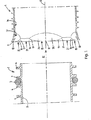
図1に、本発明に係る第1のパイプ部分のソケット端部1と、関連の差し込み端部2との特定の実施形態の長手方向の図を示し、差し込み端部2は、第1のパイプ部分と第2のパイプ部分とをパイプ連結するために、ソケット端部1内に挿入する必要がある。 FIG. 1 shows a longitudinal view of a particular embodiment of a socket end 1 of a first pipe part according to the invention and an associated plug end 2, the plug end 2 being a first pipe In order to pipe-connect the part and the second pipe part, it is necessary to insert them into the socket end 1.
ここに示す実施形態では、差し込み端部2は、比較的薄い壁3を有するパイプ部分の端部であり、薄い壁3には、外側に外周リブ4が設けられる。密閉リング5が、2つのリブ4同士の間に配置される。しかしながら、差し込み端部はまた、別の形状でもよく、例えば、厚い壁を具えるように設計してもよく、この場合、密閉リングは、壁の外周側に配置された溝に配置される。
In the embodiment shown here, the insertion end 2 is the end of a pipe portion having a relatively
端縁11から見たソケット端部1の内側に、ソケット端部1の中心軸線12に向かって斜めにテーパー状をした部分13を有し、その目的は、差し込み端部2をソケット端部1内に差し込み、隣接する円筒形部14を有するときに密閉リング5の外径を小さくすることである。
Inside the socket end 1 as viewed from the end edge 11, it has a
ソケット端部1の斜めにテーパー状をした部分13は、円周上に等間隔に配置された少なくとも2つの領域15を有し、これらの領域15では、斜めにテーパー状をした部分13の角度がソケット端部1の中心軸線12に対して円周方向に変化する。各領域15において、領域15の側部16および17に沿って、斜めにテーパー状をした部分13は、円周方向に見ると、ソケット端部1の中心軸線12に対して第1の角度α1であり(図4を参照)、領域15の中央18では、少なくとも部分的に、ソケット端部1の中心軸線12に対して第1の角度αより狭い第2の角度α2である(図7を参照)。ここに示す実施形態では、斜めにテーパー状をした部分は、各領域15の中央18では、ソケット端部1の中心軸線12に対して第2の角度α2である。
The obliquely
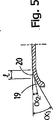
側部16および17と、各領域15の中央18との間において、斜めにテーパー状をした部分が、中心軸線12に対して、第1の角度α1でソケット端部1の端縁11の側に配置された部分19と、第2の角度α2でソケット端部1の円筒形部14の側に配置された隣接した部分20とにある(図5および図6を参照)。この場合、第2の角度α2の部分20の軸方向の長さlは、側部16および17から領域15の中央18に向かって徐々に長くなる。
Between the
別の角度の領域15同士の間に、斜めにテーパー状をした部分が、中心軸線12に対して第1の角度α1である領域21がある。
Between the
ソケット端部1(図2を参照)の領域15の寸法について以下のことが成り立つ。上述の角度α1および角度α2の構成を有する端縁11の場所におけるソケット端部1の円筒形部14の内径をD1、斜めにテーパー状をした部分13の内径をD2とした場合、端縁11の場所における角度α2の部分の半径をR1とする。半径R1は、ソケット端部の中心軸線12から距離R2の箇所から始まる。この場合、以下のことが成り立つ。
−ソケット端部の端縁11において、R1=(0.25〜0.5)D1、好ましくは(0.3〜0.35)D1、
−α1=(0.3〜0.5)α2、
−R1+R2=0.5D2、
−角度α1の領域21は、ソケット端部の円周の30%未満を占め(これは、R1の選択により異なることは、明らかである)、
−好ましくは、斜めにテーパー状をした部分13から円筒形部14にかけて、3mmから10mmの半径の丸みが設けられる。
The following holds true for the dimensions of the
At the edge 11 of the socket end, R1 = (0.25-0.5) D1, preferably (0.3-0.35) D1,
-Α1 = (0.3-0.5) α2,
−R1 + R2 = 0.5D2,
The
-Preferably, a radius of 3 mm to 10 mm is provided from the obliquely
上述のソケット端部を使用することによって、差し込み端部2を挿入するとき、密閉リング5が、断面において変形することになり、ここに示した実施形態では、関連の所定の力が時間の経過に伴って分散されてかかる結果として、密閉リング5の外径は、断面において小さくなって、所定の挿入力が低減され得る。 By using the socket end described above, the sealing ring 5 will be deformed in cross-section when the insertion end 2 is inserted, and in the illustrated embodiment, the associated predetermined force is a function of time. As a result, the outer diameter of the sealing ring 5 becomes smaller in cross section, and the predetermined insertion force can be reduced.
ソケット端部1は、添付の特許請求の範囲内のままで、上述のものと異なる設計にしてもよい。 The socket end 1 may be designed differently than that described above, while remaining within the scope of the appended claims.
Claims (3)
前記ソケット端部(1)の内側は、前記ソケット端部(1)の端縁(11)から見て、斜めにテーパー状をした部分(13)を備えており、当該テーパー状をした部分(13)は、前記ソケット端部(1)の内側の円周に沿って延び、かつ、前記差し込み端部(2)が前記ソケット端部(1)に差し込まれたときに、前記密閉リング(5)を変形させるために、前記ソケット端部(1)の中心軸線(12)に向かって斜めにテーパー状をしており、
前記ソケット端部(1)の内側は、前記斜めにテーパー状をした部分(13)よりも前記端縁(11)から内側で、かつ、当該斜めにテーパー状をした部分(13)に隣接する円筒形部(14)を有し、
前記斜めにテーパー状をした部分(13)は、当該斜めにテーパー状をした部分(13)の円周上に規則的に配置された少なくとも2つの領域(15)を有し、前記各領域(15)は、円周方向に見たとき、中央(18)及び側部(16、17)を有し、
前記領域(15)の前記各側部(16、17)に沿って、前記斜めにテーパー状をした部分(13)は、前記ソケット端部(1)の中心軸線(12)に対して第1の角度(α1)であり、
前記領域(15)の前記中央(18)は、少なくとも部分的に、前記ソケット端部の前記中心軸(12)に対して第2の角度(α2)であり、
前記第2の角度(α2)は、前記第1の角度(α1)より小さく、
隣接する前記端縁(11)に位置する部分(19)であって、前記各側部(16、17)と各領域(15)の中央(18)との間に延びる部分(19)では、前記斜めにテーパー状をした部分(13)が、前記第1の角度(α1)で配置されており、
隣接した部分(20)であって、前記ソケット端部の前記円筒形部(14)の側部上の前記部分(19)に隣接する部分(20)では、前記斜めにテーパー状をした部分(13)が、前記第2の角度(α2)で配置されており、
前記第2の角度(α2)で配置された隣接した部分(20)の軸方向の長さは、前記各側部(16、17)から前記領域(15)の中央(18)に向かって徐々に長くなることを特徴とするパイプ部分。 A pipe part provided with a socket end (1) adapted to receive the insertion end (2) of the second pipe part, wherein a sealing ring is provided outside the insertion end (2) (5) is provided,
The inside of the socket end (1) is provided with an obliquely tapered portion (13) when viewed from the end edge (11) of the socket end (1), and the tapered portion ( 13) extends along the inner circumference of the socket end (1), and when the insertion end (2) is inserted into the socket end (1), the sealing ring (5 ), The taper is tapered toward the central axis (12) of the socket end (1),
The inner side of the socket end (1) is closer to the inner side from the edge (11) than the obliquely tapered portion (13) and adjacent to the obliquely tapered portion (13). Having a cylindrical part (14);
The obliquely tapered portion (13) has at least two regions (15) regularly arranged on the circumference of the obliquely tapered portion (13). 15) has a center (18) and sides (16, 17) when viewed in the circumferential direction;
The diagonally tapered portion (13) along the side portions (16, 17) of the region (15) is first with respect to the central axis (12) of the socket end (1). Angle (α1),
The center (18) of the region (15) is at least partially at a second angle (α2) with respect to the central axis (12) of the socket end;
The second angle (α2) is smaller than the first angle (α1),
In a portion (19) located at the adjacent edge (11) and extending between each side (16, 17) and the center (18) of each region (15), The obliquely tapered portion (13) is disposed at the first angle (α1);
In the adjacent part (20), the part (20) adjacent to the part (19) on the side of the cylindrical part (14) of the socket end, the obliquely tapered part ( 13) are arranged at the second angle (α2),
The length in the axial direction of the adjacent portions (20) arranged at the second angle (α2) gradually increases from the side portions (16, 17) toward the center (18) of the region (15). A pipe part characterized by being long.
Applications Claiming Priority (3)
| Application Number | Priority Date | Filing Date | Title |
|---|---|---|---|
| NL1026990 | 2004-09-08 | ||
| NL1026990A NL1026990C2 (en) | 2004-09-08 | 2004-09-08 | Pipe part provided with a socket end part. |
| PCT/NL2005/000585 WO2006028365A1 (en) | 2004-09-08 | 2005-08-10 | Pipe section provided with a socket end part |
Publications (3)
| Publication Number | Publication Date |
|---|---|
| JP2008512623A JP2008512623A (en) | 2008-04-24 |
| JP2008512623A5 JP2008512623A5 (en) | 2008-09-18 |
| JP4785853B2 true JP4785853B2 (en) | 2011-10-05 |
Family
ID=34973226
Family Applications (1)
| Application Number | Title | Priority Date | Filing Date |
|---|---|---|---|
| JP2007531094A Expired - Fee Related JP4785853B2 (en) | 2004-09-08 | 2005-08-10 | Pipe part with socket end |
Country Status (19)
| Country | Link |
|---|---|
| US (1) | US7748754B2 (en) |
| EP (1) | EP1789714B1 (en) |
| JP (1) | JP4785853B2 (en) |
| AT (1) | ATE483932T1 (en) |
| AU (1) | AU2005280792B2 (en) |
| BR (1) | BRPI0515054B1 (en) |
| CA (1) | CA2578344A1 (en) |
| DE (1) | DE602005024024D1 (en) |
| DK (1) | DK1789714T3 (en) |
| HR (1) | HRP20100632T1 (en) |
| MX (1) | MX2007002794A (en) |
| NL (1) | NL1026990C2 (en) |
| NO (1) | NO338141B1 (en) |
| NZ (1) | NZ553474A (en) |
| PL (1) | PL1789714T3 (en) |
| RU (1) | RU2370698C2 (en) |
| UA (1) | UA90114C2 (en) |
| WO (1) | WO2006028365A1 (en) |
| ZA (1) | ZA200701785B (en) |
Families Citing this family (11)
| Publication number | Priority date | Publication date | Assignee | Title |
|---|---|---|---|---|
| JP2008089294A (en) * | 2006-09-04 | 2008-04-17 | Matsushita Electric Ind Co Ltd | Outdoor unit for air conditioner |
| ATE489578T1 (en) | 2008-01-30 | 2010-12-15 | Wavin Bv | PIPE CONNECTION STRUCTURE |
| NZ588879A (en) * | 2008-05-30 | 2012-07-27 | Contech Engineered Solutions LLC | A plastic pipe joint spigot member with metal insert that engages with a bell end structure and contains solid ribs and a gasket |
| ES2386053B1 (en) * | 2010-06-24 | 2013-06-24 | Antoun Nicolas Salame Gourdak | FLUID DRIVING |
| CN112072582A (en) * | 2013-12-31 | 2020-12-11 | 福州欧冠创新工业设计有限公司 | Double-row socket set |
| US11560972B2 (en) | 2017-04-18 | 2023-01-24 | Cobalt Coupler Systems, LLC | Oil and gas pipe connector |
| US10962157B2 (en) | 2017-04-18 | 2021-03-30 | Cobalt Coupler Systems, LLC | Coupler |
| US11060646B2 (en) | 2017-04-18 | 2021-07-13 | Cobalt Coupler Systems, LLC | Coupler |
| WO2019082400A1 (en) * | 2017-10-24 | 2019-05-02 | 古河電気工業株式会社 | Electric wire tube, electric wire tube connection structure, bell block, method for connecting electric wire tubes, method for connecting electric wire tube and bell block, tube joint, and ring member |
| DK3703208T3 (en) | 2017-10-24 | 2023-01-09 | Furukawa Electric Co Ltd | Electric wire pipe, connection structure of electric wire pipe, bell block, method of connection of electric wire pipes, method of connection of electric wire pipe and bell block, pipe connection and ring element |
| FR3098880A1 (en) * | 2019-07-18 | 2021-01-22 | Akwel | Fluidic connection for fluid transfer. |
Family Cites Families (13)
| Publication number | Priority date | Publication date | Assignee | Title |
|---|---|---|---|---|
| US1234609A (en) * | 1916-11-28 | 1917-07-24 | Harry Overton Bernard | Culvert-pipe. |
| US2315792A (en) * | 1941-04-21 | 1943-04-06 | Arthur B Hoss | Adapter |
| US3066959A (en) * | 1958-12-29 | 1962-12-04 | White Harry | Vent pipes concurrently locked against axial and rotational displacement |
| US3304104A (en) * | 1964-05-04 | 1967-02-14 | Vibraseal Corp | Tube coupling |
| US3638973A (en) * | 1969-06-04 | 1972-02-01 | Charles Ellis Poletti | Joint means for use in work supporting arm |
| US3695643A (en) * | 1970-05-18 | 1972-10-03 | Hancock Brick & Tile Co | Corrugated tube coupling means |
| US3958425A (en) * | 1972-02-23 | 1976-05-25 | Plastic Tubing, Inc. | Corrugated plastic drainage pipe with integral coupler |
| US3831954A (en) | 1972-11-24 | 1974-08-27 | Cretex Co Inc | Gasket joint connections |
| DE3921075A1 (en) * | 1989-06-28 | 1991-01-03 | Wilhelm Hegler | PLASTIC TUBE FOR PIPE RENOVATION |
| DE3928700C1 (en) * | 1989-08-30 | 1990-11-29 | Rehau Ag & Co | |
| DE20214631U1 (en) * | 2002-09-20 | 2004-02-19 | Voss Automotive Gmbh | Adapter intermediate ring for a screw-in part of a fluid connector system |
| US6932118B2 (en) * | 2002-09-24 | 2005-08-23 | The Boeing Company | Low chamfer angled torque tube end fitting metal |
| US7363945B2 (en) * | 2002-09-24 | 2008-04-29 | The Boeing Co. | Low chamfer angled torque tube end fitting with elongated overflow groove |
-
2004
- 2004-09-08 NL NL1026990A patent/NL1026990C2/en not_active IP Right Cessation
-
2005
- 2005-08-10 US US11/661,985 patent/US7748754B2/en not_active Expired - Fee Related
- 2005-08-10 ZA ZA200701785A patent/ZA200701785B/en unknown
- 2005-08-10 UA UAA200703815A patent/UA90114C2/en unknown
- 2005-08-10 WO PCT/NL2005/000585 patent/WO2006028365A1/en active Application Filing
- 2005-08-10 DE DE602005024024T patent/DE602005024024D1/en active Active
- 2005-08-10 AU AU2005280792A patent/AU2005280792B2/en active Active
- 2005-08-10 MX MX2007002794A patent/MX2007002794A/en active IP Right Grant
- 2005-08-10 NZ NZ553474A patent/NZ553474A/en not_active IP Right Cessation
- 2005-08-10 BR BRPI0515054-0A patent/BRPI0515054B1/en not_active IP Right Cessation
- 2005-08-10 AT AT05772664T patent/ATE483932T1/en not_active IP Right Cessation
- 2005-08-10 RU RU2007112936/06A patent/RU2370698C2/en not_active IP Right Cessation
- 2005-08-10 EP EP05772664A patent/EP1789714B1/en active Active
- 2005-08-10 CA CA002578344A patent/CA2578344A1/en not_active Abandoned
- 2005-08-10 DK DK05772664.8T patent/DK1789714T3/en active
- 2005-08-10 JP JP2007531094A patent/JP4785853B2/en not_active Expired - Fee Related
- 2005-08-10 PL PL05772664T patent/PL1789714T3/en unknown
-
2007
- 2007-04-04 NO NO20071777A patent/NO338141B1/en unknown
-
2010
- 2010-11-23 HR HR20100632T patent/HRP20100632T1/en unknown
Also Published As
| Publication number | Publication date |
|---|---|
| ZA200701785B (en) | 2008-08-27 |
| WO2006028365A1 (en) | 2006-03-16 |
| RU2370698C2 (en) | 2009-10-20 |
| ATE483932T1 (en) | 2010-10-15 |
| AU2005280792A1 (en) | 2006-03-16 |
| EP1789714B1 (en) | 2010-10-06 |
| BRPI0515054A (en) | 2008-07-01 |
| DK1789714T3 (en) | 2010-11-08 |
| US7748754B2 (en) | 2010-07-06 |
| BRPI0515054B1 (en) | 2017-12-19 |
| NO338141B1 (en) | 2016-08-01 |
| DE602005024024D1 (en) | 2010-11-18 |
| PL1789714T3 (en) | 2011-01-31 |
| NL1026990C2 (en) | 2006-03-09 |
| CA2578344A1 (en) | 2006-03-16 |
| NZ553474A (en) | 2010-12-24 |
| AU2005280792B2 (en) | 2010-05-20 |
| HRP20100632T1 (en) | 2010-12-31 |
| UA90114C2 (en) | 2010-04-12 |
| NO20071777L (en) | 2007-04-04 |
| EP1789714A1 (en) | 2007-05-30 |
| MX2007002794A (en) | 2007-05-18 |
| US20080191469A1 (en) | 2008-08-14 |
| RU2007112936A (en) | 2008-10-20 |
| JP2008512623A (en) | 2008-04-24 |
Similar Documents
| Publication | Publication Date | Title |
|---|---|---|
| JP4785853B2 (en) | Pipe part with socket end | |
| EP3346173B1 (en) | Press fitting and joint assembly with such a press fitting | |
| US8043111B2 (en) | Connector | |
| US5058907A (en) | Pipe joint gasket with annular anchoring heel | |
| JP2018537826A (en) | Plug connector socket | |
| EP1669652A1 (en) | Pipe joint structures and methods of manufacturing such structures | |
| KR101670111B1 (en) | Push-fit pipe fitting system with support sleeve | |
| JP2008512623A5 (en) | ||
| EP3043099B1 (en) | Sealing member for pipe connection comprising protrusions | |
| JP6580797B2 (en) | Assembly having contact elements and electrical conductors and method for manufacturing the assembly | |
| US6309228B2 (en) | C-shaped compliant contact | |
| EP1036970A2 (en) | A push fit attachment | |
| JPS59117983A (en) | Joint | |
| KR100369298B1 (en) | Universal connecting ASS'Y of steering axis for vehicle | |
| JP4648763B2 (en) | Pipe fitting | |
| JP4178307B2 (en) | Stainless steel pipe end corrosion prevention structure and stainless steel pipe end corrosion prevention insulation sleeve | |
| JP4701012B2 (en) | Pipe fitting | |
| JPH0717911Y2 (en) | elbow | |
| JP6656985B2 (en) | Coaxial cable caulking ring | |
| JP2005016235A (en) | Connection structure of segment | |
| JP4383535B2 (en) | Steel pipe fitting | |
| JP2816656B2 (en) | Manufacturing method of pipe fittings | |
| JP2005226791A (en) | Flange fixing structure of pipe | |
| JP2005232783A (en) | Segment joint structure | |
| KR20080001400U (en) | A pipe jointing structure |
Legal Events
| Date | Code | Title | Description |
|---|---|---|---|
| A521 | Request for written amendment filed |
Free format text: JAPANESE INTERMEDIATE CODE: A523 Effective date: 20080731 |
|
| A621 | Written request for application examination |
Free format text: JAPANESE INTERMEDIATE CODE: A621 Effective date: 20080731 |
|
| TRDD | Decision of grant or rejection written | ||
| A01 | Written decision to grant a patent or to grant a registration (utility model) |
Free format text: JAPANESE INTERMEDIATE CODE: A01 Effective date: 20110614 |
|
| A01 | Written decision to grant a patent or to grant a registration (utility model) |
Free format text: JAPANESE INTERMEDIATE CODE: A01 |
|
| A61 | First payment of annual fees (during grant procedure) |
Free format text: JAPANESE INTERMEDIATE CODE: A61 Effective date: 20110712 |
|
| R150 | Certificate of patent or registration of utility model |
Free format text: JAPANESE INTERMEDIATE CODE: R150 |
|
| FPAY | Renewal fee payment (event date is renewal date of database) |
Free format text: PAYMENT UNTIL: 20140722 Year of fee payment: 3 |
|
| R250 | Receipt of annual fees |
Free format text: JAPANESE INTERMEDIATE CODE: R250 |
|
| R250 | Receipt of annual fees |
Free format text: JAPANESE INTERMEDIATE CODE: R250 |
|
| R250 | Receipt of annual fees |
Free format text: JAPANESE INTERMEDIATE CODE: R250 |
|
| R250 | Receipt of annual fees |
Free format text: JAPANESE INTERMEDIATE CODE: R250 |
|
| LAPS | Cancellation because of no payment of annual fees |