EP1789714B1 - Pipe section provided with a socket end part - Google Patents
Pipe section provided with a socket end part Download PDFInfo
- Publication number
- EP1789714B1 EP1789714B1 EP05772664A EP05772664A EP1789714B1 EP 1789714 B1 EP1789714 B1 EP 1789714B1 EP 05772664 A EP05772664 A EP 05772664A EP 05772664 A EP05772664 A EP 05772664A EP 1789714 B1 EP1789714 B1 EP 1789714B1
- Authority
- EP
- European Patent Office
- Prior art keywords
- end part
- socket end
- angle
- obliquely tapering
- pipe section
- Prior art date
- Legal status (The legal status is an assumption and is not a legal conclusion. Google has not performed a legal analysis and makes no representation as to the accuracy of the status listed.)
- Active
Links
- 238000007789 sealing Methods 0.000 claims abstract description 15
- 230000004323 axial length Effects 0.000 claims description 2
- 238000003780 insertion Methods 0.000 description 4
- 230000037431 insertion Effects 0.000 description 4
- 230000007704 transition Effects 0.000 description 1
Images

Classifications
-
- F—MECHANICAL ENGINEERING; LIGHTING; HEATING; WEAPONS; BLASTING
- F16—ENGINEERING ELEMENTS AND UNITS; GENERAL MEASURES FOR PRODUCING AND MAINTAINING EFFECTIVE FUNCTIONING OF MACHINES OR INSTALLATIONS; THERMAL INSULATION IN GENERAL
- F16L—PIPES; JOINTS OR FITTINGS FOR PIPES; SUPPORTS FOR PIPES, CABLES OR PROTECTIVE TUBING; MEANS FOR THERMAL INSULATION IN GENERAL
- F16L21/00—Joints with sleeve or socket
- F16L21/02—Joints with sleeve or socket with elastic sealing rings between pipe and sleeve or between pipe and socket, e.g. with rolling or other prefabricated profiled rings
- F16L21/035—Joints with sleeve or socket with elastic sealing rings between pipe and sleeve or between pipe and socket, e.g. with rolling or other prefabricated profiled rings placed around the spigot end before connection
-
- F—MECHANICAL ENGINEERING; LIGHTING; HEATING; WEAPONS; BLASTING
- F16—ENGINEERING ELEMENTS AND UNITS; GENERAL MEASURES FOR PRODUCING AND MAINTAINING EFFECTIVE FUNCTIONING OF MACHINES OR INSTALLATIONS; THERMAL INSULATION IN GENERAL
- F16L—PIPES; JOINTS OR FITTINGS FOR PIPES; SUPPORTS FOR PIPES, CABLES OR PROTECTIVE TUBING; MEANS FOR THERMAL INSULATION IN GENERAL
- F16L21/00—Joints with sleeve or socket
- F16L21/06—Joints with sleeve or socket with a divided sleeve or ring clamping around the pipe-ends
- F16L21/065—Joints with sleeve or socket with a divided sleeve or ring clamping around the pipe-ends tightened by tangentially-arranged threaded pins
-
- F—MECHANICAL ENGINEERING; LIGHTING; HEATING; WEAPONS; BLASTING
- F16—ENGINEERING ELEMENTS AND UNITS; GENERAL MEASURES FOR PRODUCING AND MAINTAINING EFFECTIVE FUNCTIONING OF MACHINES OR INSTALLATIONS; THERMAL INSULATION IN GENERAL
- F16L—PIPES; JOINTS OR FITTINGS FOR PIPES; SUPPORTS FOR PIPES, CABLES OR PROTECTIVE TUBING; MEANS FOR THERMAL INSULATION IN GENERAL
- F16L47/00—Connecting arrangements or other fittings specially adapted to be made of plastics or to be used with pipes made of plastics
- F16L47/06—Connecting arrangements or other fittings specially adapted to be made of plastics or to be used with pipes made of plastics with sleeve or socket formed by or in the pipe end
- F16L47/065—Connecting arrangements or other fittings specially adapted to be made of plastics or to be used with pipes made of plastics with sleeve or socket formed by or in the pipe end with sealing rings arranged between outer surface of pipe and inner surface of sleeve or socket, the sealing rings being placed previously on the male part
Definitions
- the invention relates to a pipe section provided with a socket end part which is intended for accommodating a spigot end part of a second pipe section, the exterior of the spigot end part being provided with a sealing ring and the interior of the socket end part, viewed from the end edge, having a part obliquely tapering towards the centre axis of the socket end part for deforming the sealing ring when the spigot end part and an adjoining cylindrical part are inserted into the socket end part, the part of the socket end part obliquely tapering towards the centre axis having at least two areas distributed regularly over the circumference in which the angle of the obliquely tapering part varies relative to the centre axis of the socket end part in the circumferential direction, in such a manner that in each area, along the sides of the area, the obliquely tapering part, viewed in the circumferential direction, is at a first angle relative to the centre axis of the socket end part and, in the centre of the area, is at least partly at
- a pipe section of this type is known from US 3,831,954 , in particular Fig. 8 and 10.
- Another example is disclosed in WO 2004 029499 .
- the axial position of the obliquely tapering part varies over the circumference of the socket end part.
- the obliquely tapering part is corrugated in the axial direction.
- the pitch varies and thus also the length of the obliquely tapering part over the circumference of the socket end part.
- the pipe section can be produced using a simpler die than in the case of the pipe sections with socket end parts according to Fig. 8-10 of US 3,831,954 .
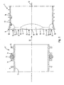
- Fig. 1 shows a longitudinal view of a specific embodiment of a socket end part 1 of a first pipe section according to the invention and an associated spigot end part 2 which has to be inserted into the socket end part 1 in order to form a pipe connection between the first pipe section and the second pipe section.
- the spigot end part 2 is an end part of a pipe section with a relatively thin wall 3 which is provided on the outside with circumferential ribs 4.
- a sealing ring 5 is arranged between two ribs 4.
- the spigot end part may also have another shape, for example be designed to have a thick wall, in which case the sealing ring is disposed in a circumferential groove arranged on the exterior in the wall.
- the interior of the socket end part 1 has, viewed from the end edge 11, a part 13 obliquely tapering towards the centre axis 12 of the socket end part 1 in order to reduce the outer diameter of the sealing ring 5 when the spigot end part 2 is inserted into the socket end part 1 and has an adjoining cylindrical part 14.
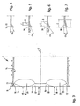
- the obliquely tapering part 13 of the socket end part 1 has at least two areas 15 distributed regularly over the circumference in which the angle of the obliquely tapering part 13 varies relative to the centre axis 12 of the socket end part 1 in the circumferential direction.
- the obliquely tapering part 13 viewed in the circumferential direction, is at a first angle al relative to the centre axis 12 of the socket end part 1 (see Fig. 4 ) and, in the centre 18 of the area 15, is at least partly at a second angle ⁇ 2 relative to the centre axis 12 of the socket end part 1 which is smaller than the first angle ⁇ 1 (see Fig. 7 ).
- the obliquely tapering part is at the second angle ⁇ 2 relative to the centre axis 12 of the socket end part 1 in the centre 18 of each area 15.
- the obliquely tapering part is in a part 19 situated on the side of the end edge 11 of the socket end part 1 at the first angle ⁇ 1 and in an adjoining part 20 situated at the side of the cylindrical part 14 of the socket end part 1 at the second angle ⁇ 2 relative to the centre axis 12 (see Fig. 5 and 6 ).
- the axial length 1 of the part 20 which is at the second angle ⁇ 2 gradually increases from the sides 16 and 17 towards the centre 18 of the area 15.
- the part which is at an angle ⁇ 2 at the location of the end edge 11 has a radius R1.
- the radius R1 starts from a point which is at a distance R2 from the centre axis 12 of the socket end part.
- the socket end part 1 may be of a different design to that described above while still remaining within the scope of the attached claims.
Landscapes
- Engineering & Computer Science (AREA)
- General Engineering & Computer Science (AREA)
- Mechanical Engineering (AREA)
- Joints With Sleeves (AREA)
- Joints Allowing Movement (AREA)
- Food-Manufacturing Devices (AREA)
- Containers And Packaging Bodies Having A Special Means To Remove Contents (AREA)
- Quick-Acting Or Multi-Walled Pipe Joints (AREA)
- Flanged Joints, Insulating Joints, And Other Joints (AREA)
- Mutual Connection Of Rods And Tubes (AREA)
- Forms Removed On Construction Sites Or Auxiliary Members Thereof (AREA)
- Control And Other Processes For Unpacking Of Materials (AREA)
Abstract
Description
- The invention relates to a pipe section provided with a socket end part which is intended for accommodating a spigot end part of a second pipe section, the exterior of the spigot end part being provided with a sealing ring and the interior of the socket end part, viewed from the end edge, having a part obliquely tapering towards the centre axis of the socket end part for deforming the sealing ring when the spigot end part and an adjoining cylindrical part are inserted into the socket end part, the part of the socket end part obliquely tapering towards the centre axis having at least two areas distributed regularly over the circumference in which the angle of the obliquely tapering part varies relative to the centre axis of the socket end part in the circumferential direction, in such a manner that in each area, along the sides of the area, the obliquely tapering part, viewed in the circumferential direction, is at a first angle relative to the centre axis of the socket end part and, in the centre of the area, is at least partly at a second angle relative to the centre axis of the socket end part which is smaller than the first angle.
- A pipe section of this type is known from
US 3,831,954 , in particular Fig. 8 and 10. Another example is disclosed inWO 2004 029499 . - Well-known pipe sections, in which the obliquely tapering part extends parallel to a plane at right angles to the centre axis of the pipe section, have the disadvantage that when a spigot end part which is provided with a sealing ring is inserted into the socket end part, the insertion force is in many cases considered to be undesirably great. The great insertion force results from the fact that when the spigot end part is inserted, the sealing ring has to be deformed over the entire circumference at the same time, which generally involves having to reduce the sealing ring's outer diameter.
US 3,831,954 (Fig. 8-10) proposes two solutions to this problem. With the first solution (Fig. 9), the axial position of the obliquely tapering part varies over the circumference of the socket end part. The obliquely tapering part is corrugated in the axial direction. With the second solution (Fig. 10), the pitch varies and thus also the length of the obliquely tapering part over the circumference of the socket end part. - It is an object of the invention to provide an improved pipe section of the type mentioned in the introduction.
- This object is achieved according to the invention with a pipe section as in
claim 1. - Through the measures according to the invention, the insertion force required for inserting the spigot end part into the socket end part is reduced further. In addition, the pipe section can be produced using a simpler die than in the case of the pipe sections with socket end parts according to Fig. 8-10 of
US 3,831,954 . - Preferred embodiments of the pipe section according to the invention are defined in the subclaims.
- The invention will be described in more detail below by way of a number of exemplary embodiments with reference to the drawing, in which:
-
Fig. 1 shows a longitudinal view of a specific embodiment of a socket end part of a pipe section according to the invention and an associated.spigot end part of a second pipe section; -
Fig. 2 shows a head end view of the socket end part fromFig.1 , viewed in the direction of the arrow II inFig. 1 ; -
Fig. 3 shows the socket end part fromFig. 1 in a longitudinal view along the line III-III inFig. 2 ; -
Fig. 4 to 7 inclusive show an end part of the wall of the socket end part fromFig. 1 in longitudinal sections along the lines IV-IV, V-V, VI-VI and VII-VII inFig. 2 . -
Fig. 1 shows a longitudinal view of a specific embodiment of asocket end part 1 of a first pipe section according to the invention and an associated spigot end part 2 which has to be inserted into thesocket end part 1 in order to form a pipe connection between the first pipe section and the second pipe section. - In the embodiment shown, the spigot end part 2 is an end part of a pipe section with a relatively
thin wall 3 which is provided on the outside withcircumferential ribs 4. A sealing ring 5 is arranged between tworibs 4. However, the spigot end part may also have another shape, for example be designed to have a thick wall, in which case the sealing ring is disposed in a circumferential groove arranged on the exterior in the wall. - The interior of the
socket end part 1 has, viewed from theend edge 11, apart 13 obliquely tapering towards thecentre axis 12 of thesocket end part 1 in order to reduce the outer diameter of the sealing ring 5 when the spigot end part 2 is inserted into thesocket end part 1 and has an adjoiningcylindrical part 14. - The obliquely tapering
part 13 of thesocket end part 1 has at least twoareas 15 distributed regularly over the circumference in which the angle of the obliquelytapering part 13 varies relative to thecentre axis 12 of thesocket end part 1 in the circumferential direction. In eacharea 15, along thesides area 15, the obliquely taperingpart 13, viewed in the circumferential direction, is at a first angle al relative to thecentre axis 12 of the socket end part 1 (seeFig. 4 ) and, in thecentre 18 of thearea 15, is at least partly at a second angle α2 relative to thecentre axis 12 of thesocket end part 1 which is smaller than the first angle α1 (seeFig. 7 ). In the embodiment shown, the obliquely tapering part is at the second angle α2 relative to thecentre axis 12 of thesocket end part 1 in thecentre 18 of eacharea 15. - Between the
sides centre 18 of eacharea 15, the obliquely tapering part is in apart 19 situated on the side of theend edge 11 of thesocket end part 1 at the first angle α1 and in anadjoining part 20 situated at the side of thecylindrical part 14 of thesocket end part 1 at the second angle α2 relative to the centre axis 12 (seeFig. 5 and 6 ). In this case, theaxial length 1 of thepart 20 which is at the second angle α2 gradually increases from thesides centre 18 of thearea 15. - Between the
areas 15 with a varying angle, there areareas 21 in which the obliquely tapering part is at the first angle α1 relative to thecentre axis 12. - The following applies with regard to the dimensions of the
areas 15 of the socket end part 1 (seeFig. 2 ). With an internal diameter D1 of thecylindrical part 14 of thesocket end part 1 and an internal diameter D2 of the obliquely taperingpart 13 at the location of theend edge 11 with the configuration of the angles α1 and α2 described above, the part which is at an angle α2 at the location of theend edge 11 has a radius R1. The radius R1 starts from a point which is at a distance R2 from thecentre axis 12 of the socket end part. In this case, the following applies: - R1 = (0.25 to 0.5) D1, preferably (0.3 to 0.35) D1, at the
end edge 11 of the socket end part, - α1 = (0.3 to 0.5) α2,
- R1 + R2 = 0.5D2,
- the
areas 21 which are at an angle α1 should occupy less than 30% of the circumference of the socket end part (this obviously depends on the choice for R1), - preferable, the transition from the obliquely
tapering part 13 to thecylindrical part 14 is provided with a rounding having a radius of 3 to 10 mm. - Using the above-described socket end part results in the sealing ring 5 being deformed in sections when the spigot end part 2 is being inserted and, in the embodiment shown, the outer diameter of the sealing ring 5 is reduced in sections, as a result of which the associated required force can be applied distributed over time and the required insertion force can be reduced.
- The
socket end part 1 may be of a different design to that described above while still remaining within the scope of the attached claims.
Claims (2)
- A pipe section provided with a socket end part (1) which is adapted for accommodating a spigot end part (2) of a second pipe section, wherein the exterior of the spigot end (2) is provided with a sealing ring (5),
the interior of the socket end part (1),viewed from the end edge (11) of the socket end part (1), having an obliquely tapering part (13), which extends along the circumference of the interior of the socket end part (1) and is obliquely tapering towards the centre axis (12) of the socket end part (1) for deforming the sealing ring (5) when the spigot end part (2) is inserted into the socket end part (1),
the interior of the socket end part (1) having an adjoining cylindrical part (14), further inwards from said end edge (11) than said obliquely tapering part (13) and adjoining the obliquely tapering part (13),
the obliquely tapering part (13) having at least two areas (15) distributed regularly over the circumference of the obliquely tapering part (13), each of said areas (15) having - when viewed in circumferential direction - a centre (18) and sides (16, 17),
wherein along each of the sides (16, 17) of the area (15), the obliquely tapering part (13) is at a first angle (α1) relative to the centre axis (12) of the socket end part (1),
characterized in that,
in the centre (18) of the area (15), the obliquely tapering part (13) is at least partly at a second angle (α2) relative to the centre axis (12) of the socket end part,
and in that the second angle (α2) is smaller than the first angle (α1),
and in that
in a part (19) which is situated adjacent the end edge (11), which part (19) extends between each of the sides (16, 17) and the centre (18) of each area (15), the obliquely tapering part (13) is arranged at the first angle (α1),
and in that
in an adjoining part (20), which adjoining part (20) adjoins said part (19) on the side of the cylindrical part (14) of the socket end part, the obliquely tapering part (13) is arranged at the second angle (α2),
and in that
the axial length (1) of the adjoining part (20) arranged at the second angle (α2) gradually increases from each of the sides (16, 17) towards the centre (18) of the area (15). - Pipe section according to claim 1, in which an adjoining part (20) - at the centre (18) of the area (15) - adjoins the free edge (11) of the socket end part (1).
Priority Applications (1)
| Application Number | Priority Date | Filing Date | Title |
|---|---|---|---|
| PL05772664T PL1789714T3 (en) | 2004-09-08 | 2005-08-10 | Pipe section provided with a socket end part |
Applications Claiming Priority (2)
| Application Number | Priority Date | Filing Date | Title |
|---|---|---|---|
| NL1026990A NL1026990C2 (en) | 2004-09-08 | 2004-09-08 | Pipe part provided with a socket end part. |
| PCT/NL2005/000585 WO2006028365A1 (en) | 2004-09-08 | 2005-08-10 | Pipe section provided with a socket end part |
Publications (2)
| Publication Number | Publication Date |
|---|---|
| EP1789714A1 EP1789714A1 (en) | 2007-05-30 |
| EP1789714B1 true EP1789714B1 (en) | 2010-10-06 |
Family
ID=34973226
Family Applications (1)
| Application Number | Title | Priority Date | Filing Date |
|---|---|---|---|
| EP05772664A Active EP1789714B1 (en) | 2004-09-08 | 2005-08-10 | Pipe section provided with a socket end part |
Country Status (19)
| Country | Link |
|---|---|
| US (1) | US7748754B2 (en) |
| EP (1) | EP1789714B1 (en) |
| JP (1) | JP4785853B2 (en) |
| AT (1) | ATE483932T1 (en) |
| AU (1) | AU2005280792B2 (en) |
| BR (1) | BRPI0515054B1 (en) |
| CA (1) | CA2578344A1 (en) |
| DE (1) | DE602005024024D1 (en) |
| DK (1) | DK1789714T3 (en) |
| HR (1) | HRP20100632T1 (en) |
| MX (1) | MX2007002794A (en) |
| NL (1) | NL1026990C2 (en) |
| NO (1) | NO338141B1 (en) |
| NZ (1) | NZ553474A (en) |
| PL (1) | PL1789714T3 (en) |
| RU (1) | RU2370698C2 (en) |
| UA (1) | UA90114C2 (en) |
| WO (1) | WO2006028365A1 (en) |
| ZA (1) | ZA200701785B (en) |
Families Citing this family (11)
| Publication number | Priority date | Publication date | Assignee | Title |
|---|---|---|---|---|
| JP2008089294A (en) * | 2006-09-04 | 2008-04-17 | Matsushita Electric Ind Co Ltd | Outdoor unit for air conditioner |
| ES2355284T3 (en) | 2008-01-30 | 2011-03-24 | Wavin B.V. | HOSE STRUCTURE. |
| AU2009260492B2 (en) * | 2008-05-30 | 2013-10-24 | Contech Engineered Solutions LLC | Pipe joint and related method |
| ES2386053B1 (en) * | 2010-06-24 | 2013-06-24 | Antoun Nicolas Salame Gourdak | FLUID DRIVING |
| CN112018690A (en) * | 2013-12-31 | 2020-12-01 | 福州欧冠创新工业设计有限公司 | Two-position socket set |
| US11560972B2 (en) | 2017-04-18 | 2023-01-24 | Cobalt Coupler Systems, LLC | Oil and gas pipe connector |
| US11060646B2 (en) | 2017-04-18 | 2021-07-13 | Cobalt Coupler Systems, LLC | Coupler |
| US10962157B2 (en) | 2017-04-18 | 2021-03-30 | Cobalt Coupler Systems, LLC | Coupler |
| AU2017437359B2 (en) * | 2017-10-24 | 2020-11-05 | Furukawa Electric Co.,Ltd. | Electric wire tube, electric wire tube connection structure, bell block, method for connecting electric wire tubes, method for connecting electric wire tube and bell block, tube joint, and ring member |
| JP6391903B1 (en) | 2017-10-24 | 2018-09-19 | 古河電気工業株式会社 | Conduit, Conduit connection structure, Bell block, Conduit connection method, Conduit tube and Bell block connection method, Pipe joint, and Ring member |
| FR3098880A1 (en) * | 2019-07-18 | 2021-01-22 | Akwel | Fluidic connection for fluid transfer. |
Family Cites Families (13)
| Publication number | Priority date | Publication date | Assignee | Title |
|---|---|---|---|---|
| US1234609A (en) * | 1916-11-28 | 1917-07-24 | Harry Overton Bernard | Culvert-pipe. |
| US2315792A (en) | 1941-04-21 | 1943-04-06 | Arthur B Hoss | Adapter |
| US3066959A (en) * | 1958-12-29 | 1962-12-04 | White Harry | Vent pipes concurrently locked against axial and rotational displacement |
| US3304104A (en) * | 1964-05-04 | 1967-02-14 | Vibraseal Corp | Tube coupling |
| US3638973A (en) * | 1969-06-04 | 1972-02-01 | Charles Ellis Poletti | Joint means for use in work supporting arm |
| US3695643A (en) * | 1970-05-18 | 1972-10-03 | Hancock Brick & Tile Co | Corrugated tube coupling means |
| US3958425A (en) * | 1972-02-23 | 1976-05-25 | Plastic Tubing, Inc. | Corrugated plastic drainage pipe with integral coupler |
| US3831954A (en) | 1972-11-24 | 1974-08-27 | Cretex Co Inc | Gasket joint connections |
| DE3921075A1 (en) * | 1989-06-28 | 1991-01-03 | Wilhelm Hegler | PLASTIC TUBE FOR PIPE RENOVATION |
| DE3928700C1 (en) * | 1989-08-30 | 1990-11-29 | Rehau Ag & Co | |
| DE20214631U1 (en) * | 2002-09-20 | 2004-02-19 | Voss Automotive Gmbh | Adapter intermediate ring for a screw-in part of a fluid connector system |
| US6932118B2 (en) * | 2002-09-24 | 2005-08-23 | The Boeing Company | Low chamfer angled torque tube end fitting metal |
| US7363945B2 (en) * | 2002-09-24 | 2008-04-29 | The Boeing Co. | Low chamfer angled torque tube end fitting with elongated overflow groove |
-
2004
- 2004-09-08 NL NL1026990A patent/NL1026990C2/en not_active IP Right Cessation
-
2005
- 2005-08-10 AT AT05772664T patent/ATE483932T1/en not_active IP Right Cessation
- 2005-08-10 DK DK05772664.8T patent/DK1789714T3/en active
- 2005-08-10 JP JP2007531094A patent/JP4785853B2/en not_active Expired - Fee Related
- 2005-08-10 UA UAA200703815A patent/UA90114C2/en unknown
- 2005-08-10 ZA ZA200701785A patent/ZA200701785B/en unknown
- 2005-08-10 DE DE602005024024T patent/DE602005024024D1/en active Active
- 2005-08-10 PL PL05772664T patent/PL1789714T3/en unknown
- 2005-08-10 MX MX2007002794A patent/MX2007002794A/en active IP Right Grant
- 2005-08-10 NZ NZ553474A patent/NZ553474A/en not_active IP Right Cessation
- 2005-08-10 AU AU2005280792A patent/AU2005280792B2/en active Active
- 2005-08-10 CA CA002578344A patent/CA2578344A1/en not_active Abandoned
- 2005-08-10 BR BRPI0515054-0A patent/BRPI0515054B1/en not_active IP Right Cessation
- 2005-08-10 WO PCT/NL2005/000585 patent/WO2006028365A1/en active Application Filing
- 2005-08-10 RU RU2007112936/06A patent/RU2370698C2/en not_active IP Right Cessation
- 2005-08-10 US US11/661,985 patent/US7748754B2/en not_active Expired - Fee Related
- 2005-08-10 EP EP05772664A patent/EP1789714B1/en active Active
-
2007
- 2007-04-04 NO NO20071777A patent/NO338141B1/en unknown
-
2010
- 2010-11-23 HR HR20100632T patent/HRP20100632T1/en unknown
Also Published As
| Publication number | Publication date |
|---|---|
| US7748754B2 (en) | 2010-07-06 |
| CA2578344A1 (en) | 2006-03-16 |
| PL1789714T3 (en) | 2011-01-31 |
| BRPI0515054B1 (en) | 2017-12-19 |
| AU2005280792B2 (en) | 2010-05-20 |
| NO338141B1 (en) | 2016-08-01 |
| JP2008512623A (en) | 2008-04-24 |
| BRPI0515054A (en) | 2008-07-01 |
| ATE483932T1 (en) | 2010-10-15 |
| DK1789714T3 (en) | 2010-11-08 |
| ZA200701785B (en) | 2008-08-27 |
| NZ553474A (en) | 2010-12-24 |
| DE602005024024D1 (en) | 2010-11-18 |
| WO2006028365A1 (en) | 2006-03-16 |
| EP1789714A1 (en) | 2007-05-30 |
| UA90114C2 (en) | 2010-04-12 |
| AU2005280792A1 (en) | 2006-03-16 |
| RU2370698C2 (en) | 2009-10-20 |
| NL1026990C2 (en) | 2006-03-09 |
| JP4785853B2 (en) | 2011-10-05 |
| HRP20100632T1 (en) | 2010-12-31 |
| NO20071777L (en) | 2007-04-04 |
| US20080191469A1 (en) | 2008-08-14 |
| RU2007112936A (en) | 2008-10-20 |
| MX2007002794A (en) | 2007-05-18 |
Similar Documents
| Publication | Publication Date | Title |
|---|---|---|
| EP1789714B1 (en) | Pipe section provided with a socket end part | |
| US6435568B1 (en) | Tube joint having tightening member for accommodating tubes of varying wall thickness | |
| US6158784A (en) | Connector for tubular members | |
| CN102597593B (en) | Hose connector | |
| US5775740A (en) | Structure and process for jointing small-diameter thin metal tube and pressure rubber hose | |
| CN100572884C (en) | Connection part with moulding inclined-plane | |
| EP2180224A2 (en) | Pipe joint | |
| KR20070046145A (en) | Metallic cutting ring | |
| US4838582A (en) | Flexible expansion pipe coupling | |
| EP1705416A1 (en) | Joint for systems, for example a thermo-sanitary system | |
| GB2349931A (en) | A push fit attachment with grip ring having at least one notched tooth | |
| US7837236B2 (en) | Pipe connection having a reshaped pipe | |
| JP4781220B2 (en) | Pipe fitting and backup ring used for it | |
| JP4925965B2 (en) | Pipe end anticorrosion core | |
| CN100529499C (en) | Pipe joint | |
| EP2113706B1 (en) | Press fit connector with improved coupling part for holding a press sleeve | |
| US11796097B2 (en) | Coupling part for a hose coupling | |
| US20010033079A1 (en) | Insert coupling | |
| JP4486343B2 (en) | Pipe holding member for resin pipe fittings | |
| EP1236002A1 (en) | Seal | |
| JP4648763B2 (en) | Pipe fitting | |
| CN101238317B (en) | Coupling for a fluid line arrangement | |
| JP4701012B2 (en) | Pipe fitting | |
| JP5236689B2 (en) | Pipe fitting | |
| NL1025979C2 (en) | Pipe part provided with a beveled key end part. |
Legal Events
| Date | Code | Title | Description |
|---|---|---|---|
| PUAI | Public reference made under article 153(3) epc to a published international application that has entered the european phase |
Free format text: ORIGINAL CODE: 0009012 |
|
| 17P | Request for examination filed |
Effective date: 20070227 |
|
| AK | Designated contracting states |
Kind code of ref document: A1 Designated state(s): AT BE BG CH CY CZ DE DK EE ES FI FR GB GR HU IE IS IT LI LT LU LV MC NL PL PT RO SE SI SK TR |
|
| AX | Request for extension of the european patent |
Extension state: AL BA HR MK |
|
| 17Q | First examination report despatched |
Effective date: 20070904 |
|
| RAX | Requested extension states of the european patent have changed |
Extension state: HR Payment date: 20070227 Extension state: BA Payment date: 20070227 Extension state: AL Payment date: 20070227 Extension state: MK Payment date: 20070227 |
|
| GRAP | Despatch of communication of intention to grant a patent |
Free format text: ORIGINAL CODE: EPIDOSNIGR1 |
|
| GRAS | Grant fee paid |
Free format text: ORIGINAL CODE: EPIDOSNIGR3 |
|
| GRAA | (expected) grant |
Free format text: ORIGINAL CODE: 0009210 |
|
| AK | Designated contracting states |
Kind code of ref document: B1 Designated state(s): AT BE BG CH CY CZ DE DK EE ES FI FR GB GR HU IE IS IT LI LT LU LV MC NL PL PT RO SE SI SK TR |
|
| AX | Request for extension of the european patent |
Extension state: AL BA HR MK |
|
| REG | Reference to a national code |
Ref country code: GB Ref legal event code: FG4D |
|
| REG | Reference to a national code |
Ref country code: RO Ref legal event code: EPE |
|
| REG | Reference to a national code |
Ref country code: CH Ref legal event code: EP |
|
| REG | Reference to a national code |
Ref country code: NL Ref legal event code: T3 |
|
| REG | Reference to a national code |
Ref country code: DK Ref legal event code: T3 |
|
| REG | Reference to a national code |
Ref country code: IE Ref legal event code: FG4D |
|
| REF | Corresponds to: |
Ref document number: 602005024024 Country of ref document: DE Date of ref document: 20101118 Kind code of ref document: P |
|
| REG | Reference to a national code |
Ref country code: HR Ref legal event code: TUEP Ref document number: P20100632 Country of ref document: HR Ref country code: SE Ref legal event code: TRGR |
|
| REG | Reference to a national code |
Ref country code: HR Ref legal event code: T1PR Ref document number: P20100632 Country of ref document: HR |
|
| REG | Reference to a national code |
Ref country code: SK Ref legal event code: T3 Ref document number: E 8100 Country of ref document: SK |
|
| REG | Reference to a national code |
Ref country code: PL Ref legal event code: T3 |
|
| PG25 | Lapsed in a contracting state [announced via postgrant information from national office to epo] |
Ref country code: SI Free format text: LAPSE BECAUSE OF FAILURE TO SUBMIT A TRANSLATION OF THE DESCRIPTION OR TO PAY THE FEE WITHIN THE PRESCRIBED TIME-LIMIT Effective date: 20101006 |
|
| REG | Reference to a national code |
Ref country code: HU Ref legal event code: AG4A Ref document number: E009032 Country of ref document: HU |
|
| PG25 | Lapsed in a contracting state [announced via postgrant information from national office to epo] |
Ref country code: IS Free format text: LAPSE BECAUSE OF FAILURE TO SUBMIT A TRANSLATION OF THE DESCRIPTION OR TO PAY THE FEE WITHIN THE PRESCRIBED TIME-LIMIT Effective date: 20110206 Ref country code: AT Free format text: LAPSE BECAUSE OF FAILURE TO SUBMIT A TRANSLATION OF THE DESCRIPTION OR TO PAY THE FEE WITHIN THE PRESCRIBED TIME-LIMIT Effective date: 20101006 Ref country code: PT Free format text: LAPSE BECAUSE OF FAILURE TO SUBMIT A TRANSLATION OF THE DESCRIPTION OR TO PAY THE FEE WITHIN THE PRESCRIBED TIME-LIMIT Effective date: 20110207 Ref country code: BG Free format text: LAPSE BECAUSE OF FAILURE TO SUBMIT A TRANSLATION OF THE DESCRIPTION OR TO PAY THE FEE WITHIN THE PRESCRIBED TIME-LIMIT Effective date: 20110106 |
|
| PG25 | Lapsed in a contracting state [announced via postgrant information from national office to epo] |
Ref country code: GR Free format text: LAPSE BECAUSE OF FAILURE TO SUBMIT A TRANSLATION OF THE DESCRIPTION OR TO PAY THE FEE WITHIN THE PRESCRIBED TIME-LIMIT Effective date: 20110107 |
|
| PG25 | Lapsed in a contracting state [announced via postgrant information from national office to epo] |
Ref country code: ES Free format text: LAPSE BECAUSE OF FAILURE TO SUBMIT A TRANSLATION OF THE DESCRIPTION OR TO PAY THE FEE WITHIN THE PRESCRIBED TIME-LIMIT Effective date: 20110117 |
|
| PLBE | No opposition filed within time limit |
Free format text: ORIGINAL CODE: 0009261 |
|
| STAA | Information on the status of an ep patent application or granted ep patent |
Free format text: STATUS: NO OPPOSITION FILED WITHIN TIME LIMIT |
|
| 26N | No opposition filed |
Effective date: 20110707 |
|
| REG | Reference to a national code |
Ref country code: DE Ref legal event code: R097 Ref document number: 602005024024 Country of ref document: DE Effective date: 20110707 |
|
| REG | Reference to a national code |
Ref country code: HR Ref legal event code: PBON Ref document number: P20100632 Country of ref document: HR Effective date: 20110811 |
|
| PG25 | Lapsed in a contracting state [announced via postgrant information from national office to epo] |
Ref country code: MC Free format text: LAPSE BECAUSE OF NON-PAYMENT OF DUE FEES Effective date: 20110831 |
|
| REG | Reference to a national code |
Ref country code: CH Ref legal event code: PL |
|
| PG25 | Lapsed in a contracting state [announced via postgrant information from national office to epo] |
Ref country code: LI Free format text: LAPSE BECAUSE OF NON-PAYMENT OF DUE FEES Effective date: 20110831 Ref country code: SK Free format text: LAPSE BECAUSE OF NON-PAYMENT OF DUE FEES Effective date: 20110810 Ref country code: CH Free format text: LAPSE BECAUSE OF NON-PAYMENT OF DUE FEES Effective date: 20110831 |
|
| REG | Reference to a national code |
Ref country code: SK Ref legal event code: MM4A Ref document number: E 8100 Country of ref document: SK Effective date: 20110810 |
|
| PG25 | Lapsed in a contracting state [announced via postgrant information from national office to epo] |
Ref country code: RO Free format text: LAPSE BECAUSE OF NON-PAYMENT OF DUE FEES Effective date: 20101006 |
|
| PGFP | Annual fee paid to national office [announced via postgrant information from national office to epo] |
Ref country code: LT Payment date: 20120807 Year of fee payment: 8 Ref country code: IE Payment date: 20120821 Year of fee payment: 8 Ref country code: EE Payment date: 20120813 Year of fee payment: 8 Ref country code: FI Payment date: 20120813 Year of fee payment: 8 Ref country code: GB Payment date: 20120808 Year of fee payment: 8 |
|
| PGFP | Annual fee paid to national office [announced via postgrant information from national office to epo] |
Ref country code: LV Payment date: 20120810 Year of fee payment: 8 Ref country code: TR Payment date: 20120807 Year of fee payment: 8 |
|
| PGFP | Annual fee paid to national office [announced via postgrant information from national office to epo] |
Ref country code: IT Payment date: 20120820 Year of fee payment: 8 Ref country code: FR Payment date: 20120906 Year of fee payment: 8 Ref country code: HU Payment date: 20120904 Year of fee payment: 8 |
|
| PG25 | Lapsed in a contracting state [announced via postgrant information from national office to epo] |
Ref country code: CY Free format text: LAPSE BECAUSE OF EXPIRATION OF PROTECTION Effective date: 20101006 Ref country code: LU Free format text: LAPSE BECAUSE OF NON-PAYMENT OF DUE FEES Effective date: 20110810 |
|
| REG | Reference to a national code |
Ref country code: LT Ref legal event code: MM4D Effective date: 20130810 |
|
| REG | Reference to a national code |
Ref country code: EE Ref legal event code: MM4A Ref document number: E004763 Country of ref document: EE Effective date: 20130831 |
|
| GBPC | Gb: european patent ceased through non-payment of renewal fee |
Effective date: 20130810 |
|
| PG25 | Lapsed in a contracting state [announced via postgrant information from national office to epo] |
Ref country code: HU Free format text: LAPSE BECAUSE OF NON-PAYMENT OF DUE FEES Effective date: 20130811 Ref country code: LT Free format text: LAPSE BECAUSE OF NON-PAYMENT OF DUE FEES Effective date: 20130810 Ref country code: EE Free format text: LAPSE BECAUSE OF NON-PAYMENT OF DUE FEES Effective date: 20130831 Ref country code: FI Free format text: LAPSE BECAUSE OF NON-PAYMENT OF DUE FEES Effective date: 20130810 |
|
| REG | Reference to a national code |
Ref country code: IE Ref legal event code: MM4A |
|
| REG | Reference to a national code |
Ref country code: FR Ref legal event code: ST Effective date: 20140430 |
|
| PG25 | Lapsed in a contracting state [announced via postgrant information from national office to epo] |
Ref country code: LV Free format text: LAPSE BECAUSE OF NON-PAYMENT OF DUE FEES Effective date: 20130810 Ref country code: IT Free format text: LAPSE BECAUSE OF NON-PAYMENT OF DUE FEES Effective date: 20130810 |
|
| PG25 | Lapsed in a contracting state [announced via postgrant information from national office to epo] |
Ref country code: IE Free format text: LAPSE BECAUSE OF NON-PAYMENT OF DUE FEES Effective date: 20130810 Ref country code: GB Free format text: LAPSE BECAUSE OF NON-PAYMENT OF DUE FEES Effective date: 20130810 |
|
| PG25 | Lapsed in a contracting state [announced via postgrant information from national office to epo] |
Ref country code: FR Free format text: LAPSE BECAUSE OF NON-PAYMENT OF DUE FEES Effective date: 20130902 |
|
| PG25 | Lapsed in a contracting state [announced via postgrant information from national office to epo] |
Ref country code: TR Free format text: LAPSE BECAUSE OF NON-PAYMENT OF DUE FEES Effective date: 20130810 |
|
| PGFP | Annual fee paid to national office [announced via postgrant information from national office to epo] |
Ref country code: NL Payment date: 20230816 Year of fee payment: 19 |
|
| PGFP | Annual fee paid to national office [announced via postgrant information from national office to epo] |
Ref country code: CZ Payment date: 20230731 Year of fee payment: 19 |
|
| PGFP | Annual fee paid to national office [announced via postgrant information from national office to epo] |
Ref country code: SE Payment date: 20230821 Year of fee payment: 19 Ref country code: PL Payment date: 20230727 Year of fee payment: 19 Ref country code: DK Payment date: 20230817 Year of fee payment: 19 Ref country code: DE Payment date: 20230816 Year of fee payment: 19 Ref country code: BE Payment date: 20230816 Year of fee payment: 19 |