JP4783480B1 - Cutting equipment - Google Patents

Cutting equipment Download PDF

Info

Publication number
JP4783480B1
JP4783480B1 JP2011078941A JP2011078941A JP4783480B1 JP 4783480 B1 JP4783480 B1 JP 4783480B1 JP 2011078941 A JP2011078941 A JP 2011078941A JP 2011078941 A JP2011078941 A JP 2011078941A JP 4783480 B1 JP4783480 B1 JP 4783480B1
Authority
JP
Japan
Prior art keywords
groove
rail body
cutting blade
groove forming
cutting
Prior art date
Legal status (The legal status is an assumption and is not a legal conclusion. Google has not performed a legal analysis and makes no representation as to the accuracy of the status listed.)
Active
Application number
JP2011078941A
Other languages
Japanese (ja)
Other versions
JP2012214971A (en
Inventor
良美 松居
文幸 竹内
崇 土屋
Current Assignee (The listed assignees may be inaccurate. Google has not performed a legal analysis and makes no representation or warranty as to the accuracy of the list.)
Estech Corp
Original Assignee
Estech Corp
Priority date (The priority date is an assumption and is not a legal conclusion. Google has not performed a legal analysis and makes no representation as to the accuracy of the date listed.)
Filing date
Publication date
Application filed by Estech Corp filed Critical Estech Corp
Priority to JP2011078941A priority Critical patent/JP4783480B1/en
Application granted granted Critical
Publication of JP4783480B1 publication Critical patent/JP4783480B1/en
Publication of JP2012214971A publication Critical patent/JP2012214971A/en
Active legal-status Critical Current
Anticipated expiration legal-status Critical

Links

Images

Abstract

【課題】 構成の複雑化を抑えて大型化を抑えることで、狭隘なスペースにおける切削を好適に行うことができる切削装置の提供。
【解決手段】 互いに対向する一対の対向面のうちの一方の対向面に、所定長さの溝を形成するための切削装置であって、前記対向面の間に挿入されるレール体と、溝形成方向と直交するよう対向面と平行な支軸回りに回転駆動する切削刃を備えて、該切削刃を前記レール体に沿って溝形成方向に案内する溝形成部と、前記一方の対向面側に向けてレール体を押すための押圧手段とが設けられ、前記レール体は前記押圧手段で一方の対向面側に押されることで該一方の対向面に当接する当接部を備え、前記溝形成部は、前記切削刃の外周部が前記当接部に対して一方の対向面側に突出した状態で、レール体が押圧手段で押されて一方の対向面側へ向けて移動するのに伴ってレール体とともに一方の対向面側へ向けて移動するようレール体に保持されている切削装置。
【選択図】 図1
PROBLEM TO BE SOLVED: To provide a cutting device capable of suitably performing cutting in a narrow space by suppressing the increase in size by suppressing the complication of the configuration.
A cutting device for forming a groove of a predetermined length on one of a pair of facing surfaces facing each other, a rail body inserted between the facing surfaces, and a groove A cutting blade that rotates around a spindle parallel to the facing surface so as to be orthogonal to the forming direction, a groove forming portion that guides the cutting blade in the groove forming direction along the rail body, and the one facing surface Pressing means for pressing the rail body toward the side, the rail body is provided with a contact portion that contacts the one opposing surface by being pressed to the one opposing surface side by the pressing means, The groove forming portion moves toward the one opposing surface side when the rail body is pressed by the pressing means in a state where the outer peripheral portion of the cutting blade protrudes toward the one opposing surface side with respect to the contact portion. Along with the rail body, it is held by the rail body so as to move toward one opposing surface side. Cutting equipment.
[Selection] Figure 1

Description

本発明は切削装置に関し、例えば、セメントコンクリート構造物の内部の鉄筋を電気防食するための電気防食用電極が設置される溝を形成するのに用いられる。   The present invention relates to a cutting apparatus, and is used, for example, to form a groove in which an electrode for anticorrosion for electrically preventing corrosion of a reinforcing bar inside a cement concrete structure is installed.

セメントコンクリート構造物(以下単に「コンクリート構造物」と称する)等の被切削物の表面部に、所定の長さに亘る溝を形成するための切削装置が、従来から種々提案されている(例えば、下記特許文献1参照)。また、コンクリート製の壁を切断するための切削装置も提案されている(特許文献2参照)。   Various cutting apparatuses for forming a groove having a predetermined length on a surface portion of a workpiece such as a cement concrete structure (hereinafter simply referred to as “concrete structure”) have been proposed (for example, , See Patent Document 1 below). A cutting device for cutting a concrete wall has also been proposed (see Patent Document 2).

これら切削装置は、切削方向に沿うよう所定の設置面に固定されるレール体と、コンクリート構造物の表面部に押し当てられる切削刃を備えレール体に沿って案内される溝形成部と、切削刃をコンクリート構造物の表面部に押し当てる外力を切削刃に付与するための外力付与手段とを有している。前記レール体は、固定手段を介して設置面に設置されている。また、外力付与手段は溝形成部に装着されている。   These cutting devices include a rail body fixed to a predetermined installation surface along the cutting direction, a groove forming portion guided along the rail body with a cutting blade pressed against the surface portion of the concrete structure, An external force applying means for applying an external force to the cutting blade to press the blade against the surface portion of the concrete structure. The rail body is installed on the installation surface via a fixing means. Further, the external force applying means is attached to the groove forming portion.

特許文献1の切削装置では、固定手段によってレール体を設置面に設置し、外力付与手段を駆動することで切削刃をコンクリート構造物の表面部に押し当て、切削刃を回転させつつ溝形成部をレール体に沿って移動させることで、コンクリート構造物の表面部に溝を形成する。また、特許文献2の切削装置では、固定手段によってレール体を設置面に設置し、外力付与手段を駆動することで切削刃をコンクリート構造物の表面部に押し当て、切削刃を回転させつつ溝形成部をレール体に沿って移動させることで、コンクリート製の壁を切断する。   In the cutting apparatus of Patent Document 1, the rail body is installed on the installation surface by the fixing means, and the cutting force is pressed against the surface portion of the concrete structure by driving the external force applying means, and the groove forming portion is rotated while rotating the cutting blade. Is moved along the rail body to form a groove in the surface portion of the concrete structure. Moreover, in the cutting apparatus of patent document 2, a rail body is installed in an installation surface by a fixing means, a cutting blade is pressed against the surface part of a concrete structure by driving an external force applying means, and a groove is formed while rotating the cutting blade. The concrete wall is cut by moving the forming portion along the rail body.

特公昭60−39806号公報Japanese Patent Publication No. 60-39806 特許第4454022号公報Japanese Patent No. 4445422

上記従来の切削装置では、レール体を設置面に固定する固定手段と、切削刃をコンクリート構造物の表面部に押し当てる外力を切削刃に付与するための外力付与手段とが別個に設けられている。このように、固定手段と外力付与手段とが別個に設けられると、切削装置全体の構成が複雑になり大型化してしまう。そうなると、例えば、切削刃を押し当てて溝を形成する表面部(溝形成面)が、作業者が入り込むことができない或いは困難な狭隘なスペースを構成する互いに接近して対向した一対の対向面(例えば、離間距離が10〜30cmである一対の対向面)のうちの一方の対向面であるような場合に、かかる狭隘なスペースに切削装置を挿入することができず、溝を形成することができない。   In the conventional cutting apparatus, a fixing means for fixing the rail body to the installation surface and an external force applying means for applying an external force to the cutting blade to press the cutting blade against the surface portion of the concrete structure are separately provided. Yes. As described above, if the fixing means and the external force applying means are provided separately, the configuration of the entire cutting apparatus becomes complicated and large. Then, for example, a pair of facing surfaces facing each other close to each other forming a narrow space in which a surface portion (groove forming surface) that presses a cutting blade to form a groove cannot enter or is difficult for an operator to enter. For example, in the case of one opposing surface of a pair of opposing surfaces having a separation distance of 10 to 30 cm, the cutting device cannot be inserted into such a narrow space, and a groove may be formed. Can not.

そして、このような狭隘なスペースへの切削装置の適用に関する問題は、コンクリート構造物に溝を切削する場合に限らず、例えばアスファルトコンクリートの表面部の切削や、硬度の高い木材等の表面部を切削する場合にも同様に生じる問題であった。   And the problem regarding the application of the cutting device to such a narrow space is not limited to the case of cutting a groove in a concrete structure. For example, the surface portion of asphalt concrete or the surface portion of hard wood or the like is removed. The same problem occurs when cutting.

そこで本発明は、上記課題に鑑み、構成の複雑化を抑えて大型化を抑えることで、狭隘なスペースにおける切削を好適に行うことができる切削装置の提供を目的とする。   In view of the above problems, an object of the present invention is to provide a cutting apparatus that can suitably perform cutting in a narrow space by suppressing the complication of the configuration and suppressing the increase in size.

本発明は、互いに対向する一対の対向面のうちの一方の対向面に所定長さの溝を形成するための切削装置であって、前記対向面の間に挿入されるレール体と、溝形成方向と直交するよう対向面と平行な支軸回りに回転駆動する切削刃を備えて、該切削刃を前記レール体に沿って溝形成方向に案内する溝形成部と、前記一方の対向面側に向けてレール体を押すための押圧手段とが設けられ、前記レール体は前記押圧手段で一方の対向面側に押されることで該一方の対向面に当接する当接部を備え、前記溝形成部は、前記切削刃の外周部が前記当接部に対して一方の対向面側に突出した状態で、レール体が押圧手段で押されて一方の対向面側へ向けて移動するのに伴ってレール体とともに一方の対向面側へ向けて移動するようレール体に保持されていることを特徴としている。   The present invention is a cutting device for forming a groove having a predetermined length on one of the opposing surfaces of a pair of opposing surfaces, the rail body inserted between the opposing surfaces, and the groove formation A cutting blade that rotates around a spindle parallel to the opposing surface so as to be orthogonal to the direction, a groove forming portion that guides the cutting blade in the groove forming direction along the rail body, and the one opposing surface side A pressing means for pressing the rail body toward the rail, and the rail body includes a contact portion that contacts the one opposing surface when pressed by the pressing means toward the one opposing surface, and the groove The forming portion is configured so that the rail body is pushed by the pressing means and moves toward the one opposing surface side with the outer peripheral portion of the cutting blade protruding toward the one opposing surface side with respect to the contact portion. Along with the rail body, it is held by the rail body so as to move toward one opposing surface side. It is characterized in that there.

上記構成において、レール体が押圧手段で一方の対向面側に押されることで当接部が一方の対向面に当接してレール体が位置決め固定され、溝形成部はレール体の一方の対向面側への移動に伴ってレール体とともに移動し、溝形成部に備えられている切削刃も一方の対向面側へ移動して、切削刃が一方の対向面に押圧されるから、レール体の一方の対向面への位置決め固定と、切削刃の一方の対向面への押圧とが、一つの押圧手段で兼用される。   In the above configuration, the rail body is pushed to one opposing surface side by the pressing means, so that the abutting portion comes into contact with the one opposing surface and the rail body is positioned and fixed, and the groove forming portion is one of the opposing surfaces of the rail body. Since the cutting blade provided in the groove forming portion also moves to one facing surface side and is pressed against the one facing surface, the cutting blade is pressed against the one facing surface. Positioning and fixing to one facing surface and pressing to one facing surface of the cutting blade are combined with one pressing means.

本発明の切削装置では、当接部は切削刃に対して支軸の軸線方向の両側に配置され、レール体は、前記当接部に対して他方の対向面側に離間して配置されて溝形成部を溝形成方向に案内する案内面を備え、溝形成部は当接部と案内面との間に保持されている構成を採用することができる。   In the cutting apparatus according to the present invention, the contact portion is disposed on both sides of the axial direction of the support shaft with respect to the cutting blade, and the rail body is disposed apart from the contact portion on the other facing surface side. A configuration may be adopted in which a guide surface that guides the groove forming portion in the groove forming direction is provided, and the groove forming portion is held between the contact portion and the guide surface.

上記構成において、溝形成部は、レール体において当接部と案内面の間に収納された形態となり、レール体の外部へ突出する部分を主として切削刃のみとすることが可能になって、装置全体の、対向面間に挿入される高さが小さくなる。   In the above configuration, the groove forming portion is housed between the abutment portion and the guide surface in the rail body, and the portion protruding to the outside of the rail body can be mainly made of only the cutting blade. The total height inserted between the opposing surfaces is reduced.

本発明の切削装置では、切削刃は溝形成部に備えた駆動モータにより駆動される構成であり、溝形成部は前記駆動モータがその長手方向を溝形成方向に沿うようレール体に保持されている構成を採用することができる。   In the cutting apparatus of the present invention, the cutting blade is driven by a drive motor provided in the groove forming portion, and the groove forming portion is held by the rail body so that the drive motor has its longitudinal direction along the groove forming direction. A configuration can be adopted.

上記構成のように、駆動モータがその長手方向を溝形成方向に沿うようレール体に保持されていれば、その分だけ、装置全体の、対向面間に挿入される高さが小さくなる。   If the drive motor is held on the rail body so that the longitudinal direction of the drive motor is along the groove forming direction as in the above configuration, the height of the entire apparatus inserted between the opposing surfaces is reduced accordingly.

本発明の切削装置によれば、レール体が押圧手段で一方の対向面側に押されることで当接部が一方の対向面に当接してレール体が位置決め固定され、溝形成部はレール体の一方の対向面側への移動に伴ってレール体とともに移動し、溝形成部に備えられている切削刃も一方の対向面側へ移動して、切削刃が一方の対向面に押圧されるよう構成されているから、レール体の一方の対向面への位置決め固定と、切削刃の一方の対向面への押圧とを、一つの押圧手段で兼用することができ、したがって、装置全体の構成の複雑化を抑えて大型化するのを抑えることができる結果、狭隘なスペースにおける切削を好適に行うことができる。   According to the cutting device of the present invention, when the rail body is pushed by the pressing means to the one opposing surface side, the abutting portion comes into contact with the one opposing surface and the rail body is positioned and fixed, and the groove forming portion is the rail body. Along with the movement toward one of the opposing surfaces, the rail moves together with the rail body, and the cutting blade provided in the groove forming portion also moves toward the one opposing surface, and the cutting blade is pressed against the one opposing surface. Thus, the positioning and fixing of the rail body to one of the opposing surfaces and the pressing of the cutting blade to the one opposing surface can be combined with one pressing means. As a result, it is possible to suitably perform cutting in a narrow space.

本発明の一実施形態を表す切削装置の、使用状態の一部破断側面図である。It is a partially broken side view of the cutting state showing one embodiment of the present invention in use condition. 同押圧手段を含めたレール体の側面図である。It is a side view of a rail body including the pressing means. 同押圧手段を含めたレール体の背面図である。It is a rear view of the rail body including the pressing means. 同押圧手段を含めたレール体の平面図である。It is a top view of the rail body including the pressing means. 同レール間隔保持部の背面図である。It is a rear view of the rail space | interval holding | maintenance part. 同溝形成部の平面図である。It is a top view of the groove formation part. 同溝形成部の側面図である。It is a side view of the groove formation part. 同溝形成部の背面図である。It is a rear view of the groove forming part. 同溝形成部の図6におけるC−C断面矢視図である。It is CC sectional view taken on the line in FIG. 6 of the groove formation part. 同溝形成の工程(橋桁の裏面に予堀を形成した状態)を表した概略側面図である。It is the schematic side view showing the process (state in which the pre-drill was formed in the back surface of a bridge girder) of the groove formation. 同溝形成の工程(レール体を空間スペースに挿入した状態)を表した概略側面図である。It is the schematic side view showing the process (state which inserted the rail body in the space) of the groove | channel formation. 同溝形成の工程(レール体に溝形成部を装着した状態)を表した概略側面図である。It is the schematic side view showing the process (state which attached the groove formation part to the rail body) of the groove formation. 同溝形成の工程(レール体を上昇させた状態)を表した概略側面図である。It is the schematic side view showing the process (state which raised the rail body) of the groove formation. 同溝形成の工程(溝形成部を前方へ移動させて溝を形成している状態)を表した概略側面図である。It is a schematic side view showing the process of forming the groove (a state where the groove forming portion is moved forward to form a groove). 同陽極設置手順(第一モルタルを溝に充填している状態)を表した側面断面図である。It is side surface sectional drawing showing the same anode installation procedure (state which has filled the groove | channel with the 1st mortar). 同陽極設置手順(陽極を第一モルタルに押し当てている状態)を表した側面断面図である。It is side surface sectional drawing showing the same anode installation procedure (state which has pressed the anode against the 1st mortar). 同陽極設置手順(陽極を第一モルタルに押し当てている状態)を表した正面断面図である。It is front sectional drawing showing the same anode installation procedure (state which has pressed the anode against the 1st mortar). 同陽極設置手順(第二モルタルを溝に充填している状態)を表した側面断面図である。It is side surface sectional drawing showing the same anode installation procedure (state which has filled the groove | channel with the 2nd mortar). 同陽極設置装置の陽極設置部の斜視図である。It is a perspective view of the anode installation part of the same anode installation apparatus. 同陽極設置装置の陽極設置部の平面図である。It is a top view of the anode installation part of the same anode installation apparatus. 同陽極設置装置の陽極設置部の背面図である。It is a rear view of the anode installation part of the same anode installation apparatus. 同陽極設置装置の陽極設置部の、使用状態を兼用した側面図である。It is a side view which combines the use condition of the anode installation part of the same anode installation apparatus.

以下、本発明の一実施形態に係る切削装置について説明する。本実施形態に係る切削装置は、構造物の溝形成面に所定長さの溝を形成するのに用いられる。切削装置は狭隘な場所に挿入されて、該狭隘な場所で溝形成面に溝を形成するのに有用である。この溝は、例えば、構造物内部に配置された鉄筋の腐食防止のために、チタン等の金属からなる長尺の陽極(電気防食用電極)を埋設する溝として用いられる。   Hereinafter, a cutting device according to an embodiment of the present invention will be described. The cutting device according to the present embodiment is used to form a groove having a predetermined length on a groove forming surface of a structure. The cutting device is inserted in a narrow place and is useful for forming a groove on the groove forming surface in the narrow place. This groove is used, for example, as a groove for embedding a long anode (electrode for anticorrosion) made of a metal such as titanium in order to prevent corrosion of reinforcing bars arranged inside the structure.

なお、ここでいう狭隘な場所とは、一方の対向面が溝形成面である互いに対向する一対の対向面が、作業者が入り込むことができない或いは困難な程に接近した場所であり、例えば対向面間の離間距離が10〜40cmであるような場所である。   In addition, a narrow place here is a place where a pair of facing surfaces facing each other whose one facing surface is a groove forming surface cannot approach or difficult enough for an operator to enter. This is a place where the distance between the surfaces is 10 to 40 cm.

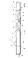
図1に示すように、切削装置1は、コンクリート構造物である橋台2の天端面3と、天端面3に上下方向で対向するコンクリート構造物であるの橋桁4の裏面5との間の狭隘な空間スペース6に挿入され、互いに対向する対向面としての天端面3と裏面5のうち、一方の対向面としての裏面5を溝形成面として、所定幅で所定の長さの溝7を形成する装置である。なおこの場合、溝7は、溝底面と、溝底面から立ち上がって横方向で対向する側面とから形成される。   As shown in FIG. 1, the cutting apparatus 1 includes a narrow space between a top end surface 3 of an abutment 2 that is a concrete structure and a back surface 5 of a bridge girder 4 that is a concrete structure facing the top end surface 3 in the vertical direction. A groove 7 having a predetermined width and a predetermined length is formed by using the back surface 5 as one opposing surface as a groove forming surface among the top end surface 3 and the back surface 5 as opposing surfaces that are inserted into a clear space 6. It is a device to do. In this case, the groove 7 is formed of a groove bottom surface and side surfaces that rise from the groove bottom surface and face each other in the lateral direction.

溝7の形成方向は、図1において矢線8で示すように、橋桁4のスパンに沿う直線方向である。したがって、以下、溝形成方向のうち、橋台2のパラペット9側を前方、その反対側である向かい合う橋台(図示せず)側を後方と定義する。また、前方に向かって左右方向(溝幅方向)を定義し、右側を一方側とし、左側を他方側とする。   The formation direction of the groove 7 is a linear direction along the span of the bridge beam 4 as indicated by an arrow 8 in FIG. Therefore, in the groove forming direction, the parapet 9 side of the abutment 2 is defined as the front side, and the opposite abutment (not shown) side as the opposite side is defined as the rear side. Moreover, the left-right direction (groove width direction) is defined toward the front, the right side is one side, and the left side is the other side.

切削装置1は、裏面5に当接するようにして使用されるレール体10と、レール体10を裏面5側(上方)に向けて押圧する押圧手段11A,11Bと、レール体10に沿って溝形成方向(前後方向)に移動可能な溝形成部12とを備えている。   The cutting device 1 includes a rail body 10 that is used so as to contact the back surface 5, pressing means 11 </ b> A and 11 </ b> B that press the rail body 10 toward the back surface 5 side (upward), and a groove along the rail body 10. And a groove forming portion 12 movable in the forming direction (front-rear direction).

図2ないし図4に示すように、前記レール体10は、天板部13と、胴部14と、案内レール15A,15Bとを備えている。特に、天板部13は3つの天板構成部材から一体的に形成されている。すなわち天板部13は、一方側の右天板部16と、他方側の左天板部17と、左右の天板部16,17の前端部どうしを一体に連結固定する連結体18とから構成され、平面視して後部を開放したコ字形に形成されることによって、左右方向の中央部分に切削刃突出用空間19を有している(特に図4参照)。   As shown in FIGS. 2 to 4, the rail body 10 includes a top plate portion 13, a body portion 14, and guide rails 15 </ b> A and 15 </ b> B. In particular, the top plate portion 13 is integrally formed from three top plate components. That is, the top plate portion 13 includes a right top plate portion 16 on one side, a left top plate portion 17 on the other side, and a connecting body 18 that integrally connects and fixes the front end portions of the left and right top plate portions 16 and 17 together. It is configured and is formed in a U shape having a rear portion opened in plan view, thereby having a cutting blade protruding space 19 in the center portion in the left-right direction (see particularly FIG. 4).

左右両側の天板部16,17どうしは、切削刃突出用空間19を介して左右方向に離間して配置されている。右天板部16は、左天板部17に比べて左右幅が小さく設定されている(左天板部17は右天板部16に比べて左右幅が大きく設定されている)。   The top and bottom plate portions 16 and 17 on both the left and right sides are spaced apart in the left-right direction via the cutting blade protruding space 19. The right top plate portion 16 is set to have a smaller left / right width than the left top plate portion 17 (the left top plate portion 17 is set to have a larger left / right width than the right top plate portion 16).

この構成により、切削刃突出用空間19の他方側端部19aが、レール体10の左右方向略中心に位置するよう、切削刃突出用空間19全体は、レール体10の左右方向中心から一方側に位置ずれして形成されている。なお、天板部13は、その上面20が平面であり、この上面20が橋桁4の裏面5に下方から当接する当接部となっている。具体的には、左右両側の天板部16,17が、切削刃突出用空間19を介して左右方向に離間して配置される一対の当接部となっており、各天板部16,17の上面が橋桁4の裏面5に下方から当接する。   With this configuration, the entire cutting blade protruding space 19 is located on one side from the center of the rail body 10 in the left-right direction so that the other end 19a of the cutting blade protrusion space 19 is positioned at the substantially center in the left-right direction of the rail body 10. The position is shifted. The top plate portion 13 has a flat upper surface 20, and the upper surface 20 is a contact portion that contacts the back surface 5 of the bridge girder 4 from below. Specifically, the top plate portions 16 and 17 on both the left and right sides are a pair of contact portions that are spaced apart in the left and right direction via the cutting blade protruding space 19, and each top plate portion 16, The upper surface of 17 contacts the back surface 5 of the bridge girder 4 from below.

胴部14は、天板部13の下側において、溝形成部12を収容するための溝形成部収容空間を形成すべく枠状に構成されており、右天板部16と左天板部17のそれぞれの下側に配置された胴部骨格部材21A,21Bを備えている。各胴部骨格部材21A,21Bは、同一の構成のものを左右対称使いしている。各胴部骨格部材21A,21Bは、具体的には溝型鋼の断面形状に形成されている。   The trunk portion 14 is configured in a frame shape to form a groove forming portion accommodating space for accommodating the groove forming portion 12 below the top plate portion 13, and includes a right top plate portion 16 and a left top plate portion. 17, body skeleton members 21 </ b> A and 21 </ b> B are provided on the lower side of each. Each trunk | skeleton part member 21A, 21B uses the thing of the same structure symmetrically. Each trunk | skeleton part member 21A, 21B is specifically formed in the cross-sectional shape of channel steel.

すなわち、各胴部骨格部材21A,21Bは、天板部13に平行な底板22,23と、底板22,23に平行で右天板部16、左天板部17のそれぞれの裏面に固定された固定板24,25と、底板22,23および固定板24,25を一体化するよう底板22,23の端部から立設(固定板24,25から垂下)する側板26,27とから正面視して断面コ字形に形成されている。   In other words, the body skeleton members 21A and 21B are fixed to the bottom plates 22 and 23 parallel to the top plate portion 13 and the back surfaces of the right top plate portion 16 and the left top plate portion 17 parallel to the bottom plates 22 and 23, respectively. The fixed plates 24, 25 and the side plates 26, 27 standing from the ends of the bottom plates 22, 23 so as to integrate the bottom plates 22, 23 and the fixed plates 24, 25 (hanging down from the fixed plates 24, 25). As viewed, it is formed in a U-shaped cross section.

また、胴部14は、各側板26,27の左右方向外側に、板状の補強リブ28を備えている。補強リブ28は、前後方向に所定間隔ごとに配置され、各補強リブ28は、底板22,23(固定板24,25)から側方に突出しない幅に設定されている。   The body portion 14 includes plate-like reinforcing ribs 28 on the outer sides in the left-right direction of the side plates 26 and 27. The reinforcing ribs 28 are arranged at predetermined intervals in the front-rear direction, and each reinforcing rib 28 is set to a width that does not protrude laterally from the bottom plates 22 and 23 (fixed plates 24 and 25).

胴部骨格部材21A,21Bは、それぞれ右天板部16と左天板部17のそれぞれの下側に配置されていることに伴い、胴部骨格部材21A,21Bどうしは、左右方向に離間して配置されている(図3参照)。各胴部骨格部材21A,21Bは、後述する理由により、前後方向途中部分を省いており、この省いている部分は、左右の胴部骨格部材21A,21Bで前後に位置ずれしている。なお、他方側の胴部骨格部材21Bは、左天板部17の左右方向略中心部に配置されている。   As the trunk skeleton members 21A and 21B are arranged below the right top plate portion 16 and the left top plate portion 17, respectively, the trunk skeleton members 21A and 21B are separated from each other in the left-right direction. (See FIG. 3). Each of the trunk skeleton members 21A and 21B omits a middle part in the front-rear direction for reasons described later, and the omitted parts are displaced forward and backward by the left and right trunk skeleton members 21A and 21B. The other side body skeleton member 21 </ b> B is disposed at a substantially central portion in the left-right direction of the left top plate portion 17.

胴部14は、胴部骨格部材21A,21Bの側板26,27の後端部に、レール間隔保持部材30(図5参照)を取付けるための取付け板部材31,32を、それぞれ左右方向外側に突出するよう一体的に備えている。取付け板部材31,32は、それぞれ側板26,27の後端部の上下方向途中に配置されている。一方側の取付け板部材31は、単純な矩形形状の下部を切除して、上部の右方への突出量に比べて、下部の右方への突出量が少ない形状に形成されている。他方側の取付け板部材32は、正面視して単純な矩形形状に形成されている。   The body part 14 has mounting plate members 31 and 32 for attaching rail spacing members 30 (see FIG. 5) on the rear ends of the side plates 26 and 27 of the body frame members 21A and 21B, respectively, on the outer sides in the left-right direction. It is provided integrally so as to protrude. The mounting plate members 31 and 32 are arranged in the middle of the rear ends of the side plates 26 and 27, respectively. The attachment plate member 31 on one side is formed in a shape that has a simple rectangular lower portion cut out and has a lower protrusion amount to the right as compared with the upper protrusion amount to the right. The mounting plate member 32 on the other side is formed in a simple rectangular shape when viewed from the front.

また、レール間隔保持部材30は、一方側の取付け板部材31と相対形状に形成されて取付け板部材31に後方から重ねられる一方側部30Aと、他方側の取付け板部材32と相対形状に形成されて取付け板部材32に後方から重ねられる他方側部30Bと、一方側部30Aおよび他方側部30Bの間の中間部30Cとから、板状に一体的に形成されている。また、一方側部30Aおよび他方側部30Bのそれぞれの板面には、取付け板部材31,32にそれぞれ形成された取付け前孔31a,32aに前後方向で合致する取付け後孔30a,30bが形成されている。   Further, the rail spacing member 30 is formed in a relative shape with the one side mounting plate member 31 and is overlapped with the mounting plate member 31 from the rear side, and the other side mounting plate member 32 is formed in a relative shape. The other side portion 30B that is superimposed on the mounting plate member 32 from the rear and the intermediate portion 30C between the one side portion 30A and the other side portion 30B are integrally formed in a plate shape. Further, post-mounting holes 30a and 30b are formed on the plate surfaces of the one side portion 30A and the other side portion 30B so as to match the pre-mounting holes 31a and 32a formed in the mounting plate members 31 and 32, respectively, in the front-rear direction. Has been.

なお、中間部30Cの途中上部は左右方向に亘って切欠かれ、後述する杆状の押圧具を挿入するための挿入用切欠30cが形成されている。そして、後孔30a,30bにそれぞれ後方から取付けボルト(図示せず)を挿入して、取付け前孔31a,32aに螺合することで、レール間隔保持部材30を取付け板部材31,32に渡すように取付けることができる。   An intermediate upper portion of the intermediate portion 30C is cut out in the left-right direction, and an insertion cutout 30c for inserting a hook-shaped pressing tool described later is formed. Then, mounting bolts (not shown) are inserted into the rear holes 30a and 30b from the rear and screwed into the mounting front holes 31a and 32a, so that the rail interval holding member 30 is passed to the mounting plate members 31 and 32. Can be installed as.

胴部14は、断面が山形鋼(不等辺山形鋼)状に形成されたカバー33A,33Bをさらに備えている。すなわちカバー33A,33Bは、上下を逆転したL字形断面に形成されており、長辺側部分34,35を左右方向外側に、短辺側部分36,37を左右方向内側にして配置されている。一方のカバー33Aは、短辺側部分36の上面が固定板24の裏面に固定されている。他方のカバー33Bは、短辺側部分37の内側端面を固定板25の外側端面に当接させるようにして、上面を左天板部17の裏面に固定されている。   The trunk | drum 14 is further provided with cover 33A, 33B in which the cross section was formed in the shape of angle iron (unequal side angle iron). That is, the covers 33A and 33B are formed in an L-shaped cross section that is upside down, and are arranged with the long side portions 34 and 35 on the outside in the left and right direction and the short side portions 36 and 37 on the inside in the left and right direction. . In one cover 33 </ b> A, the upper surface of the short side portion 36 is fixed to the back surface of the fixing plate 24. The other cover 33 </ b> B has an upper surface fixed to the back surface of the left top plate portion 17 so that the inner end surface of the short side portion 37 is in contact with the outer end surface of the fixing plate 25.

カバー33A,33Bは、それぞれ胴部骨格部材21A,21Bの後端部から、胴部骨格部材21A,21Bの前後方向途中部分を省いている位置まで延長されており、したがって、一方側と他方側のカバー33A,33Bでは、前後方向の長さが異なっている。すなわち、一方側のカバー33Aは他方側のカバー33Bよりも長い寸法に形成されている。   The covers 33A and 33B are respectively extended from the rear end portions of the trunk skeleton members 21A and 21B to positions where middle portions in the front-rear direction of the trunk skeleton members 21A and 21B are omitted. The covers 33A and 33B have different lengths in the front-rear direction. That is, the cover 33A on one side is formed to have a longer dimension than the cover 33B on the other side.

前記案内レール15A,15Bは、胴部14で形成される溝形成部収容空間内で溝形成部12を案内すべく溝形成部収容空間内に配置されている。具体的には、案内レール15A,15Bは左右一対で設けられ、それぞれ胴部骨格部材21A,21Bの対向する内側面(側板26,27)に固定されている。各案内レール15A,15Bは、左右方向に沿う上壁38,39と、上壁38,39の下側にあって上壁38,39と平行な下壁(案内壁)40,41と、上壁38,39および下壁40,41を一体に連結する縦壁42,43とから、断面コ字形に形成されている。   The guide rails 15 </ b> A and 15 </ b> B are disposed in the groove forming portion receiving space so as to guide the groove forming portion 12 in the groove forming portion receiving space formed by the body portion 14. Specifically, the guide rails 15A and 15B are provided as a pair on the left and right sides, and are fixed to the opposing inner side surfaces (side plates 26 and 27) of the trunk skeleton members 21A and 21B, respectively. Each guide rail 15A, 15B has an upper wall 38, 39 along the left-right direction, a lower wall (guide wall) 40, 41 below the upper wall 38, 39 and parallel to the upper wall 38, 39, The walls 38, 39 and the lower walls 40, 41 are formed in a U-shaped cross section from the vertical walls 42, 43 that integrally connect the walls 38, 39.

なお、本実施形態では、下壁40,41の上面は、溝形成部12を溝形成方向に案内する案内面40a,41aであり、当接部としての左右両側の天板部16,17に対して、他方の対向面としての天端面3側に離間して配置されている。また、縦壁42,43の内面は、後述の第一台車60の両側面部60a,60aで第一台車60を溝形成方向に案内するための側部案内面42a,43aである。これら案内レール15A,15Bは、胴部骨格部材21A,21Bの高さに比べて低く形成され、且つ内側面の上下方向途中の同じ高さ位置に配置され、コ字形断面の開放側が左右方向で対向(内向きで対向)している。   In the present embodiment, the upper surfaces of the lower walls 40 and 41 are guide surfaces 40a and 41a for guiding the groove forming portion 12 in the groove forming direction, and are provided on the top plate portions 16 and 17 on both the left and right sides as contact portions. On the other hand, it is spaced apart and arranged on the top end face 3 side as the other facing surface. Further, the inner surfaces of the vertical walls 42 and 43 are side guide surfaces 42a and 43a for guiding the first cart 60 in the groove forming direction with both side surfaces 60a and 60a of the first cart 60 described later. These guide rails 15A and 15B are formed lower than the height of the trunk skeleton members 21A and 21B, and are arranged at the same height position in the middle of the inner surface in the vertical direction. Opposite (facing inward).

案内レール15Aの上壁38と右天板部16との間、案内レール15Bの上壁39と左天板部17との間には、それぞれスペーサ44,45が介装されている。また、案内レール15Aの下壁40の下面と胴部骨格部材21Aの側板26の下部に亘るように、下壁40を支持するリブ状の支持部材46が一体的に取付けられている。案内レール15Bの下壁41の下面と胴部骨格部材21Bの側板27の下部に亘るように、下壁41を支持するリブ状の支持部材47が一体的に取付けられている。これら支持部材46,47は前後方向所定間隔置きに複数配置されている。   Spacers 44 and 45 are interposed between the upper wall 38 of the guide rail 15A and the right top plate portion 16, and between the upper wall 39 of the guide rail 15B and the left top plate portion 17, respectively. Further, a rib-like support member 46 that supports the lower wall 40 is integrally attached so as to cover the lower surface of the lower wall 40 of the guide rail 15A and the lower portion of the side plate 26 of the trunk skeleton member 21A. A rib-like support member 47 that supports the lower wall 41 is integrally attached so as to cover the lower surface of the lower wall 41 of the guide rail 15B and the lower portion of the side plate 27 of the trunk skeleton member 21B. A plurality of these support members 46 and 47 are arranged at predetermined intervals in the front-rear direction.

次に、前記押圧手段11A,11Bについて説明する。押圧手段11A,11Bは、レール体10の左右両側にそれぞれ一個ずつ設けられている(左右一対で設けられている)。これら押圧手段11A,11Bは、ジャッキである(図2参照)。さらに詳しくは、押圧手段11A,11Bは、リンク部材55,56,57,58を組合せてなるパンタグラフ式ジャッキである。   Next, the pressing means 11A and 11B will be described. One pressing means 11A, 11B is provided on each of the left and right sides of the rail body 10 (provided as a pair of left and right). These pressing means 11A and 11B are jacks (see FIG. 2). More specifically, the pressing means 11A and 11B are pantograph jacks in which link members 55, 56, 57, and 58 are combined.

押圧手段11A,11Bは、胴部骨格部材21A,21Bのうち、前後方向途中部分を省いた領域に配置されており、前述したように該省いた部分は、左右の胴部骨格部材21A,21Bで前後に位置ずれしているから、左右の押圧手段11A,11Bも前後方向(溝形成方向)で位置ずれして配置されている。これら一対の押圧手段11A,11Bは、何れが前で何れが後ろでもよい。本実施形態では、一方側の押圧手段11Aが他方側の押圧手段11Bに対して前方に配置されている。   The pressing means 11A, 11B are arranged in the region of the trunk skeleton members 21A, 21B where the middle part in the front-rear direction is omitted. As described above, the omitted parts are the left and right trunk skeleton members 21A, 21B. Therefore, the left and right pressing means 11A, 11B are also displaced in the front-rear direction (groove forming direction). Any one of the pair of pressing means 11A and 11B may be front and any may be rear. In the present embodiment, the pressing means 11A on one side is disposed in front of the pressing means 11B on the other side.

押圧手段11A,11Bは、その上部48,49が、それぞれ右天板部16、左天板部17の裏面の左右方向外側部分に固定されている。つまり押圧手段11A,11Bは、天板部13の左右幅内に納まっている。これによって、切削装置1がレール体10とは別に押圧手段11A,11Bを備えていても、切削装置1全体の左右幅は、レール体10の左右幅を超えないようになっている。なお、押圧手段11A,11Bの下部50,51は、レール体10には固定されることなくフリーになっている。   The upper portions 48 and 49 of the pressing means 11A and 11B are fixed to the left and right outer portions of the back surfaces of the right top plate portion 16 and the left top plate portion 17, respectively. That is, the pressing means 11 </ b> A and 11 </ b> B are contained within the left and right width of the top plate part 13. Thereby, even if the cutting device 1 includes the pressing means 11 </ b> A and 11 </ b> B separately from the rail body 10, the lateral width of the entire cutting device 1 does not exceed the lateral width of the rail body 10. The lower portions 50 and 51 of the pressing means 11A and 11B are free without being fixed to the rail body 10.

切削装置1は、押圧手段11A,11Bの上下高さ(伸縮)を操作するための操作部材52,53を備えている。この操作部材52,53は、ねじ軸部材であり、押圧手段11Aが供えたナット部材である操作ブロック54(図2の一方側の押圧手段11Aについてのみ図示する)に後方から螺合している。操作部材52,53の軸心回りの回転によって、押圧手段11A,11Bは、そのリンク部材55,56,57,58どうしの連結角度が変更されて、上下方向に伸縮するものである。また、操作部材52,53は、その軸方向途中部分がカバー33A,33Bの内側を挿通して、レール体10に回転自在に支持されている。   The cutting device 1 includes operation members 52 and 53 for operating the vertical height (extension / contraction) of the pressing means 11A and 11B. The operation members 52 and 53 are screw shaft members and are screwed from the rear to an operation block 54 (only the pressing means 11A on one side in FIG. 2 is shown) which is a nut member provided by the pressing means 11A. . By the rotation of the operation members 52 and 53 around the axis, the pressing means 11A and 11B are expanded and contracted in the vertical direction by changing the connecting angle between the link members 55, 56, 57 and 58. Further, the operation members 52 and 53 are supported by the rail body 10 so that the middle portions in the axial direction pass through the insides of the covers 33A and 33B.

次に、図6ないし図9に基づいて、前記溝形成部12について説明する。溝形成部12は、第一台車60と、第一台車60に固定された駆動モータ部61と、駆動モータ部61に備えたモータ(図示せず)の駆動軸に連結された切削刃62と、支軸保持部材63と、コンクリートの粉塵を吸引するためのダクト部64とを備える。   Next, the groove forming portion 12 will be described with reference to FIGS. The groove forming part 12 includes a first carriage 60, a drive motor part 61 fixed to the first carriage 60, and a cutting blade 62 connected to a drive shaft of a motor (not shown) provided in the drive motor part 61. The support shaft holding member 63 and a duct portion 64 for sucking concrete dust are provided.

第一台車60は、案内レール15A,15Bの下壁40,41の上面である案内面40a,41a(図7、図8参照)に沿って移動可能な被案内体である。図6に示すように、第一台車60は、平面視して前後方向を長手方向とする矩形状の板部材から形成されている。第一台車60の裏面四隅部には左右横向きの車輪軸回りに回転可能なキャスタ(車輪)65A,65Bが取付けられている。したがって、キャスタ65A,65Bは、第一台車60の裏面の前後に配置されており、また、左右両側面部にも配置されている。これらキャスタ65A,65Bが、案内レール15A,15Bの案内面40a,41aに載置されて、第一台車60が前後方向に案内される。   The first carriage 60 is a guided body that is movable along guide surfaces 40a and 41a (see FIGS. 7 and 8) that are upper surfaces of the lower walls 40 and 41 of the guide rails 15A and 15B. As shown in FIG. 6, the first carriage 60 is formed of a rectangular plate member having a longitudinal direction in the front-rear direction when seen in a plan view. Casters (wheels) 65 </ b> A and 65 </ b> B are attached to the four corners of the back surface of the first carriage 60 so as to be rotatable around the left and right lateral wheel shafts. Therefore, the casters 65A and 65B are disposed on the front and back of the back surface of the first carriage 60, and are also disposed on the left and right side surfaces. These casters 65A and 65B are placed on the guide surfaces 40a and 41a of the guide rails 15A and 15B, and the first carriage 60 is guided in the front-rear direction.

図7に示すように、第一台車60を水平に倣わせた状態において、前側にある左右一対のキャスタ65Aは、その回転中心軸(車輪軸)が、後側にある左右一対のキャスタ65Bの回転中心軸(車輪軸)よりも下方に位置するよう、取付け部材(符号省略)を介して第一台車60に取付けられている。なお、何れのキャスタ65A,65Bも同一径に設定されている。   As shown in FIG. 7, in a state in which the first carriage 60 is moved horizontally, the pair of left and right casters 65A on the front side has a rotation center axis (wheel axis) of the pair of left and right casters 65B on the rear side. It is attached to the first carriage 60 via an attachment member (not shown) so as to be positioned below the rotation center axis (wheel axis). Both casters 65A and 65B are set to have the same diameter.

第一台車60の左右両側の側端面(側面部)60a,60aは、上下方向に沿う平面(平滑面)である。これら左右両側の側端面60a,60aは、案内レール15A,15Bの縦壁42,43の内面(側部案内面に相当する)42a,43aに接触し得る面である。換言すれば、第一台車60をレール体10に装着すると、縦壁42,43の内面42a,43aによって、左右方向での変位を遊嵌的に規制される。   Side end surfaces (side portions) 60a, 60a on the left and right sides of the first carriage 60 are flat surfaces (smooth surfaces) along the vertical direction. These left and right side end surfaces 60a, 60a are surfaces that can come into contact with inner surfaces (corresponding to side guide surfaces) 42a, 43a of the vertical walls 42, 43 of the guide rails 15A, 15B. In other words, when the first carriage 60 is attached to the rail body 10, the displacement in the left-right direction is regulated loosely by the inner surfaces 42a, 43a of the vertical walls 42, 43.

図6に示すように、第一台車60の一部に、その長手方向に長く切欠かれた切欠部66が形成されている。この切欠部66は、一方側寄りの前部から後方へ向けて形成された平面視して矩形状に形成されている。また、切欠部66の前端部に、側方(左側)に向けて延長した小切欠67が連続して形成されている。   As shown in FIG. 6, a cutout portion 66 that is long in the longitudinal direction is formed in a part of the first carriage 60. The notch 66 is formed in a rectangular shape in a plan view formed from the front part closer to one side toward the rear. Further, a small notch 67 extending toward the side (left side) is continuously formed at the front end of the notch 66.

第一台車60は、これを前方に押圧するのに用いられる被押圧部材68を備えている。被押圧部材68は、第一台車60の上面60bの後端部の左右方向中心部にあって、第一台車60の上面60bに固定された基部69と、基部69の後端部から上方へ向けて延長された被押圧板70とから一体的に形成されている。被押圧板70には、左右方向に離間して一対のナット部材71が、それぞれ後方に突出するよう取付けられている。   The first cart 60 includes a pressed member 68 that is used to press it forward. The pressed member 68 is in the center in the left-right direction of the rear end portion of the upper surface 60 b of the first carriage 60, and has a base 69 fixed to the upper surface 60 b of the first carriage 60, and upward from the rear end of the base 69. It is integrally formed from the pressed plate 70 extended toward the surface. A pair of nut members 71 are attached to the pressed plate 70 so as to protrude rearward from each other while being spaced apart in the left-right direction.

駆動モータ部61は、円柱状の胴体72と、胴体72を第一台車60に固定する固定手段73と、胴体72の先端部に配置された突出部74と、突出部74から延長された非回転の軸部材75とを備える。   The drive motor unit 61 includes a cylindrical body 72, fixing means 73 that fixes the body 72 to the first carriage 60, a protrusion 74 disposed at the tip of the body 72, and a non-extension extended from the protrusion 74. A rotating shaft member 75.

胴体72は円柱状に形成されており、その内部に不図示の駆動モータが内装されている。胴体72は、駆動モータの駆動軸心72aを前後方向に沿わせて切欠部66に挿入されている。   The body 72 is formed in a columnar shape, and a drive motor (not shown) is housed therein. The body 72 is inserted into the notch 66 with the drive shaft center 72a of the drive motor extending along the front-rear direction.

固定手段73は、駆動モータ部61の駆動等による振動を緩衝する緩衝体76と、取付けベルト77とを備えている。緩衝体76は環状(筒状)の合成ゴムから形成され、胴体72全体を周方向(駆動モータの駆動軸回り)で外嵌するよう胴体72に取付けられている。緩衝体76は、胴体72の前後方向に離間して一対で設けられている。   The fixing means 73 includes a buffer body 76 that buffers vibrations caused by driving of the drive motor unit 61 and the like, and an attachment belt 77. The buffer body 76 is formed of an annular (cylindrical) synthetic rubber, and is attached to the body 72 so as to externally fit the entire body 72 in the circumferential direction (around the drive shaft of the drive motor). The buffer bodies 76 are provided as a pair spaced apart in the front-rear direction of the body 72.

取付けベルト77は、緩衝体76ごとに設けられ、緩衝体76を介して、胴体72を第一台車60に取付けるものである。各取付けベルト77は、各緩衝体76を上半分で固定する上外嵌部78と、下半分で固定する下外嵌部79とから構成されている。上外嵌部78は、緩衝体76を上半分で外嵌する円弧状部80と、第一台車60の上面60bに固定され円弧状部80の左右両側に一体的に形成された固定部81とから構成されている。下外嵌部79は、上外嵌部78と対称使いであって、緩衝体76を下半分で外嵌する円弧状部80と、第一台車60の下面に固定され円弧状部80の左右両側に一体的に形成された固定部81とから構成されている。   The attachment belt 77 is provided for each shock absorber 76 and attaches the body 72 to the first carriage 60 via the shock absorber 76. Each attachment belt 77 includes an upper outer fitting portion 78 that fixes each buffer body 76 at the upper half, and a lower outer fitting portion 79 that fixes the buffer body 76 at the lower half. The upper outer fitting portion 78 includes an arc-shaped portion 80 that externally fits the buffer body 76 in the upper half, and a fixed portion 81 that is fixed to the upper surface 60 b of the first carriage 60 and is integrally formed on the left and right sides of the arc-shaped portion 80. It consists of and. The lower outer fitting portion 79 is used symmetrically with the upper outer fitting portion 78, and has an arcuate portion 80 that externally fits the buffer body 76 in the lower half, and is fixed to the lower surface of the first carriage 60, and the left and right sides of the arcuate portion 80. It is comprised from the fixing | fixed part 81 integrally formed in both sides.

上外嵌部78と下外嵌部79の固定部81は、第一台車60の板面を貫通するボルト82により、互いに強固に第一台車60に固定されている。この構成により、取付けベルト77は、緩衝体76をその弾性に抗して圧縮するように緩衝体76に巻かれて、胴体72は第一台車60に保持されている。なお、胴体72は、緩衝体76が切欠部66の左右対向面に接触することで、該左右対向面に所定のクリアランス83を介して配置されている。   The fixing portions 81 of the upper outer fitting portion 78 and the lower outer fitting portion 79 are firmly fixed to the first cart 60 with bolts 82 that penetrate the plate surface of the first cart 60. With this configuration, the attachment belt 77 is wound around the shock absorber 76 so as to compress the shock absorber 76 against its elasticity, and the body 72 is held by the first carriage 60. The body 72 is disposed on the left and right facing surfaces with a predetermined clearance 83 when the buffer body 76 contacts the left and right facing surfaces of the notch 66.

突出部74は、胴体72の先端部に設けられており、切欠部66から前方に突出するように配置されている。この突出部74には、不図示の傘歯車機構等が内装されている。そして、該傘歯車機構等を介して前記駆動軸に連結された回転軸84(切削刃62の支軸に相当する)が、他方側に向けて水平に突出している。   The projecting portion 74 is provided at the distal end portion of the body 72 and is disposed so as to project forward from the notch portion 66. The projecting portion 74 includes a bevel gear mechanism (not shown). A rotating shaft 84 (corresponding to a support shaft of the cutting blade 62) connected to the drive shaft via the bevel gear mechanism or the like protrudes horizontally toward the other side.

すなわち、回転軸84は、その基端部側を胴体72側で片持ち支持されていて、駆動モータの駆動力は、駆動軸から回転軸84に伝達されることによって、前後方向に沿う(溝形成方向に沿う)軸心72a回りの駆動力から、左右方向に沿う(溝形成方向に直交して溝形成面である裏面5に沿う)軸心84a回りの駆動力に変換される。そして、回転軸84には、回転軸84に比べて大径の、前記軸部材75が外嵌固定されている。この軸部材75は、第一台車60の前面60cに対してさらに前方に位置付けられている。   That is, the rotary shaft 84 is cantilevered at the base end side on the body 72 side, and the driving force of the drive motor is transmitted from the drive shaft to the rotary shaft 84, thereby extending along the front-rear direction (groove). The driving force around the axis 72a (along the forming direction) is converted into the driving force around the axis 84a along the left-right direction (along the back surface 5 which is the groove forming surface perpendicular to the groove forming direction). The shaft member 75, which has a larger diameter than the rotation shaft 84, is fitted and fixed to the rotation shaft 84. The shaft member 75 is positioned further forward with respect to the front surface 60 c of the first carriage 60.

切削刃62は、形成する溝7の幅に対応する厚みを備えている。図7に示すように、切削刃62は、円盤部85と、円盤部85の外周部に周方向に所定間隔置きに、該外周部からさらに径方向外方に突出するよう形成された複数個の刃部86とから一体的に形成されている。切削刃62は、その回転中心部が、軸部材75の先端部寄りに外嵌固定されている。すなわち切削刃62は、回転軸84および軸部材75を介することで、間接的に駆動軸に連結されている。   The cutting blade 62 has a thickness corresponding to the width of the groove 7 to be formed. As shown in FIG. 7, the cutting blade 62 has a disk portion 85 and a plurality of cutting edges 62 formed on the outer peripheral portion of the disc portion 85 so as to protrude further radially outward from the outer peripheral portion at predetermined intervals in the circumferential direction. The blade portion 86 is integrally formed. The cutting blade 62 is fitted and fixed with its center of rotation close to the tip of the shaft member 75. That is, the cutting blade 62 is indirectly connected to the drive shaft through the rotating shaft 84 and the shaft member 75.

切削刃62の回転中心である支軸としての回転軸84は、前側のキャスタ65Aの回転中心である車輪軸に比べて高い位置になるよう配置されている。また、回転軸84は、前側のキャスタ65Aの車輪軸に対して前方に配置されることで、切削刃62の少なくとも外周上端部がキャスタ65Aよりも前方に位置するよう構成されている(図7参照)。   The rotation shaft 84 as a support shaft that is the rotation center of the cutting blade 62 is arranged to be higher than the wheel shaft that is the rotation center of the front caster 65A. Further, the rotation shaft 84 is arranged forward with respect to the wheel shaft of the front caster 65A, so that at least the outer peripheral upper end of the cutting blade 62 is positioned forward of the caster 65A (FIG. 7). reference).

また、切削刃62は、軸部材75の先端部に取付けられることで、第一台車60の左右方向中心に対して左側に位置ずれしている。但し、溝形成部12をレール体10に装着すると、切削刃62はレール体10の左右方向略中心に位置して、切削刃62の外周部87が切削刃突出用空間19から上方へ突出するように構成されている(図8参照)。切削刃62の切削刃突出用空間19からの突出量は、形成する溝7の深さに略一致する。そして溝7の深さは、コンクリート構造物中の鉄筋に接触しない深さで、できるだけ鉄筋に接近する状態が好ましい。   Further, the cutting blade 62 is attached to the distal end portion of the shaft member 75, so that the cutting blade 62 is displaced to the left with respect to the center of the first cart 60 in the left-right direction. However, when the groove forming portion 12 is mounted on the rail body 10, the cutting blade 62 is positioned substantially at the center in the left-right direction of the rail body 10, and the outer peripheral portion 87 of the cutting blade 62 protrudes upward from the cutting blade protruding space 19. (See FIG. 8). The protruding amount of the cutting blade 62 from the cutting blade protruding space 19 substantially matches the depth of the groove 7 to be formed. And the depth of the groove | channel 7 is the depth which does not contact the reinforcing bar in a concrete structure, and the state which approaches a reinforcing bar as much as possible is preferable.

切削刃62の径、回転軸84の位置、小切欠67の位置は、切削刃62の刃部86を含む外周部87が小切欠67に入るよう、設定されている。また切削刃62は、その径が駆動モータ部61の厚さ(上下方向の高さ)に比べて大きいものが用いられている。すなわち、切削刃62の外周部87の上端部は、駆動モータ部61の上端部よりも高い位置に位置付けられ、切削刃62の外周部87の下端部は、キャスタ65A,65Bよりも低い位置になるよう設定されている。   The diameter of the cutting blade 62, the position of the rotary shaft 84, and the position of the small notch 67 are set so that the outer peripheral portion 87 including the blade portion 86 of the cutting blade 62 enters the small notch 67. Further, the cutting blade 62 having a diameter larger than the thickness (vertical height) of the drive motor unit 61 is used. That is, the upper end portion of the outer peripheral portion 87 of the cutting blade 62 is positioned higher than the upper end portion of the drive motor portion 61, and the lower end portion of the outer peripheral portion 87 of the cutting blade 62 is positioned lower than the casters 65A and 65B. It is set to be.

支軸保持部材63は、前述のように、片持ち支持された回転軸84を保持するためのものである。換言すれば支軸保持部材63は、軸部材75を介して、切削刃62の支軸である回転軸84を保持するためのものである。   As described above, the support shaft holding member 63 is for holding the rotating shaft 84 that is cantilevered. In other words, the support shaft holding member 63 is for holding the rotating shaft 84 that is a support shaft of the cutting blade 62 via the shaft member 75.

図7および図9に示すように、支軸保持部材63は、一枚の板状に形成されており、切削刃62に対して回転軸84の軸心方向に並ぶように配置されている。具体的には、支軸保持部材63は、側面視して前後方向を長手方向とする矩形形状に形成され、長手方向の一端部側としての前部側が回転軸84を保持し、他端部側としての後部側が第一台車60に固定されるように構成されている。また、支軸保持部材63前部側の上面は、水平方向に対して前方に向けて下傾斜する傾斜面88に形成されている。傾斜面88の後側は第一台車60の上面60bに平行な面に形成され、支軸保持部材63の下面も、第一台車60の上面60bに平行な面に形成されている。   As shown in FIGS. 7 and 9, the support shaft holding member 63 is formed in a single plate shape and is arranged so as to be aligned with the cutting blade 62 in the axial direction of the rotation shaft 84. Specifically, the support shaft holding member 63 is formed in a rectangular shape whose longitudinal direction is the front-rear direction when viewed from the side, the front side as one end side in the longitudinal direction holds the rotating shaft 84, and the other end The rear side as the side is configured to be fixed to the first carriage 60. Further, the upper surface on the front side of the support shaft holding member 63 is formed as an inclined surface 88 that is inclined downward toward the front with respect to the horizontal direction. The rear side of the inclined surface 88 is formed on a surface parallel to the upper surface 60 b of the first carriage 60, and the lower surface of the support shaft holding member 63 is also formed on a surface parallel to the upper surface 60 b of the first carriage 60.

支軸保持部材63は、切削刃62の外周部87の上端部に対して上方に突出しないように、且つ切削刃62の外周部87の下端部に対して下方に突出しないように寸法設定されている。しかし支軸保持部材63は、切削刃62の外周部87の前端部に対しては、さらに前方に突出するよう設定されている。即ち、支軸保持部材63の前部の先端部としての前端部は、切削刃62よりもさらに前方に突出している。この前方に突出した前端部の前端面63aは、第一台車60を水平にした場合、上下方向に沿う平面であり、この前端面63aは、前記連結体18に後方から当接可能な面である。   The support shaft holding member 63 is dimensioned so that it does not protrude upward with respect to the upper end portion of the outer peripheral portion 87 of the cutting blade 62 and does not protrude downward with respect to the lower end portion of the outer peripheral portion 87 of the cutting blade 62. ing. However, the support shaft holding member 63 is set so as to protrude further forward with respect to the front end portion of the outer peripheral portion 87 of the cutting blade 62. In other words, the front end portion as the front end portion of the support shaft holding member 63 protrudes further forward than the cutting blade 62. The front end surface 63a of the front end portion protruding forward is a plane along the vertical direction when the first carriage 60 is leveled, and the front end surface 63a is a surface that can contact the connecting body 18 from the rear. is there.

支軸保持部材63の板面には、第一保持穴89が形成されている。第一保持穴89の前部は円弧状に形成され、後部は矩形に形成されている。前部の径は、軸部材75の径に略一致している。さらに、支軸保持部材63の後部の上下方向途中部分には、第一保持穴89に連続する第二保持穴90が形成されている。第二保持穴90は、第一保持穴89から支軸保持部材63の後端面まで延長されている。また、支軸保持部材63は、第一台車60に対して直交する上下方に沿って配置され、しかも支軸保持部材63の一部は、第一台車60から前方に突出するよう設けられている。   A first holding hole 89 is formed on the plate surface of the support shaft holding member 63. The front portion of the first holding hole 89 is formed in an arc shape, and the rear portion is formed in a rectangular shape. The diameter of the front portion substantially matches the diameter of the shaft member 75. Further, a second holding hole 90 that is continuous with the first holding hole 89 is formed in the middle portion of the rear portion of the support shaft holding member 63 in the vertical direction. The second holding hole 90 extends from the first holding hole 89 to the rear end surface of the support shaft holding member 63. Further, the support shaft holding member 63 is disposed along an upper and lower direction orthogonal to the first carriage 60, and a part of the support shaft holding member 63 is provided so as to protrude forward from the first carriage 60. Yes.

このような支軸保持部材63は、第一保持穴89の前部に軸部材75および回転軸84が内嵌されて該軸部材75および回転軸84を保持し、第一台車60の前一部601が第二保持穴90に挿通され、該前一部601と第二保持穴90形成領域の板面部分とが溶接等されて第一台車60に強固に固定されている。   In such a support shaft holding member 63, the shaft member 75 and the rotation shaft 84 are fitted inside the front portion of the first holding hole 89 to hold the shaft member 75 and the rotation shaft 84. The part 601 is inserted into the second holding hole 90, and the front part 601 and the plate surface portion of the second holding hole 90 formation region are welded or the like and firmly fixed to the first carriage 60.

ダクト部64は、第一台車60の裏面に配置されており、切削刃62に対して直ぐ後方位置で裏面に固定されたダクト91と、ダクト91に連通接続された吸塵ホース92とから構成されている。ダクト91は、切削刃62側を開口とするよう第一台車60の裏面に配置固定され、吸塵ホース92はダクト91の後端部に接続されている。そして吸塵ホース92には、不図示の吸入装置が着脱自在に接続される。   The duct portion 64 is disposed on the back surface of the first carriage 60, and includes a duct 91 fixed to the back surface at a position immediately behind the cutting blade 62, and a dust suction hose 92 connected to the duct 91. ing. The duct 91 is disposed and fixed on the back surface of the first carriage 60 so that the cutting blade 62 side is open, and the dust suction hose 92 is connected to the rear end portion of the duct 91. A suction device (not shown) is detachably connected to the dust suction hose 92.

上記構成の溝形成部12は、切削刃62を除いた全体の上下方向高さが、案内レール15A,15Bの下壁40,41の案内面40a,41aから上壁38,39の下面までの高さに比べて小さくなるよう設定されている。換言すると、溝形成部12は、切削刃62が天板部13の切削刃突出用空間19から上方に突出した状態で、天板部13の下側において胴部14で形成される溝形成部収容空間に収容されて案内レール15A,15Bに保持されている。このことにより、溝形成部12をそのキャスタ65A,65Bが案内面40a,41aに載置されるようレール体10に装着すると、上壁38,39の下面と溝形成部12(被押圧板70)の間にクリアランスが生じるようになっている。   The groove forming part 12 having the above-described configuration has an overall vertical height excluding the cutting blade 62 from the guide surfaces 40a, 41a of the lower walls 40, 41 of the guide rails 15A, 15B to the lower surfaces of the upper walls 38, 39. It is set to be smaller than the height. In other words, the groove forming portion 12 is a groove forming portion formed by the body portion 14 below the top plate portion 13 with the cutting blade 62 protruding upward from the cutting blade protruding space 19 of the top plate portion 13. It is accommodated in the accommodation space and held by the guide rails 15A and 15B. Thus, when the groove forming portion 12 is mounted on the rail body 10 so that the casters 65A and 65B are placed on the guide surfaces 40a and 41a, the lower surface of the upper walls 38 and 39 and the groove forming portion 12 (the pressed plate 70) ) Between them.

以上が、溝形成面である橋桁4の裏面5に溝7を形成するための切削装置1である。次に、上記構成の切削装置1を用いて、橋桁4の裏面5に陽極95を設置(埋設)する手順、すなわち橋桁4に対して電気防食工法を実施する手順を説明する。まず、切削装置1を用いて溝7を形成する溝形成の手順を説明する。溝形成に際しては、第一台車60と、溝形成部12を組合せて用いる。   The above is the cutting device 1 for forming the groove 7 on the back surface 5 of the bridge girder 4 which is the groove forming surface. Next, a procedure for installing (embedding) the anode 95 on the back surface 5 of the bridge girder 4 using the cutting apparatus 1 having the above-described configuration, that is, a procedure for carrying out the cathodic protection method on the bridge girder 4 will be described. First, a groove forming procedure for forming the groove 7 using the cutting device 1 will be described. In forming the groove, the first carriage 60 and the groove forming part 12 are used in combination.

まず、該溝形成の手順の概略を述べると、下記(1)〜(8)のとおりである。
(1)橋桁4の裏面5に、溝7を形成する部位を明示するためのマーキングを施す。
(2)橋台2の天端面3から後方に外れた部位に、これから形成する溝7のきっかけとなる予掘(例えば前後方向に所定の長さを有する溝状)4aを形成する。
(3)互いに対向する橋台2の天端面3と橋桁4の裏面5との間の空間スペース6にレール体10を挿入する。また、溝形成部12をレール体10の後端部側に沿わせる(挿入する)。
(4)予堀4aに切削刃62がほぼ合致するように、レール体10を空間スペース6の前後方向、左右方向で移動させる。
(5)ジャッキを伸長させてレール体10を持上げて、レール体10の当接部としての天板部13の上面20を橋桁4の裏面5に圧接させる。
(6)駆動モータ部61を駆動させて切削刃62を回転させ、溝形成部12をレール体10に沿わせて前方に移動させる。
(7)さらに溝形成部12をレール体10に沿って、前方に移動させる。
(8)溝形成部12をレール体10の最奥部(前端部)まで移動させて、なお溝7の前後方向長さを必要とする場合、ジャッキを縮めてレール体10の上面20を橋桁4の裏面5から離間させ、レール体10をさらに前方に移動して(5)〜(7)を実施する。
というものである。
First, the outline of the procedure for forming the groove is as follows (1) to (8).
(1) On the back surface 5 of the bridge girder 4, marking for clearly indicating a site where the groove 7 is formed is applied.
(2) A pre-excavation (for example, a groove shape having a predetermined length in the front-rear direction) 4a that is a trigger for the groove 7 to be formed is formed in a portion that is rearwardly removed from the top end surface 3 of the abutment 2.
(3) The rail body 10 is inserted into the space 6 between the top end surface 3 of the abutment 2 and the back surface 5 of the bridge girder 4 facing each other. Further, the groove forming portion 12 is placed (inserted) along the rear end side of the rail body 10.
(4) The rail body 10 is moved in the front-rear direction and the left-right direction of the space 6 so that the cutting blade 62 substantially matches the pre-drilling 4a.
(5) The jack is extended to lift the rail body 10, and the top surface 20 of the top plate portion 13 as a contact portion of the rail body 10 is pressed against the back surface 5 of the bridge girder 4.
(6) The drive motor unit 61 is driven to rotate the cutting blade 62, and the groove forming unit 12 is moved forward along the rail body 10.
(7) Further, the groove forming portion 12 is moved forward along the rail body 10.
(8) When the groove forming part 12 is moved to the innermost part (front end part) of the rail body 10 and the length in the front-rear direction of the groove 7 is still required, the jack is shrunk so that the upper surface 20 of the rail body 10 is bridged. 4 is separated from the back surface 5 of the No. 4, and the rail body 10 is further moved forward to carry out (5) to (7).
That's it.

次に、上記(1)〜(8)の工程について、順に詳述する。まず、(1)の工程について説明する。マーキングを施す位置は、橋桁4に埋設してある鉄筋の位置を予め知って、電気防食工法を施す鉄筋の配置に基づいた必要な位置に、橋桁4の幅員方向に所定間隔で施すことが好ましい。   Next, the steps (1) to (8) will be described in detail in order. First, the step (1) will be described. The position to be marked is preferably given at a predetermined interval in the width direction of the bridge girder 4 at a required position based on the arrangement of the reinforcing bars to which the anticorrosion method is applied by knowing in advance the position of the reinforcing bar embedded in the bridge girder 4 .

次に、(2)の工程を説明する。前記マーキング位置に、例えばコンクリートカッターなどによって予堀4aを形成する(図10参照)。なお、図10において、橋台2の天端面3に対して橋桁4を支持するヒンジ等の支持部材は省略してある。この予堀4aとしては、例えば、前端部がマーキングに連なるように前後方向に形成した所定長さの溝が考えられる。   Next, the step (2) will be described. A pre-drilling 4a is formed at the marking position by, for example, a concrete cutter (see FIG. 10). In FIG. 10, a support member such as a hinge that supports the bridge girder 4 with respect to the top end surface 3 of the abutment 2 is omitted. As this preliminary excavation 4a, for example, a groove having a predetermined length formed in the front-rear direction so that the front end portion is continuous with the marking can be considered.

予掘4aは、これから形成する溝7の本数に応じて予め形成しておくことが好ましい。また予堀4aの形成領域として、橋桁4の裏面5の橋台2の天端面3に対向する部位(空間スペース6を形成している部位)よりも後方側に外れた部位から、空間スペース6の後端部(後部入口程度)まで延長して形成しておくことが好ましい。予掘4aを形成しておく理由は、裏面5に対する切削刃62の噛込み(切削を開始するためのきっかけ)を確保するためである。   The pre-dig 4a is preferably formed in advance according to the number of grooves 7 to be formed. Moreover, as a formation area of the pre-drilling 4a, from the site | part which remove | deviated from the site | part (site | part which forms the space 6) facing the top end surface 3 of the abutment 2 of the back surface 5 of the bridge girder 4, It is preferable to extend the rear end (about the rear entrance). The reason for forming the pre-dig 4a is to secure the biting of the cutting blade 62 with respect to the back surface 5 (an opportunity to start cutting).

(3)の工程について説明する。作業者は、レール体10を、レール体10の天板部13が上側、案内レール15A,Bが下側に位置するようにして、空間スペース6の所望の位置に後方から前方に向けて挿入する(図11参照)。このとき、ジャッキは縮めておけば、切削装置1全体としての高さは低い状態であるから、空間スペース6が狭隘であったとしても、レール体10を空間スペース6に容易に挿入することができる。   The process (3) will be described. The operator inserts the rail body 10 from the rear to the front at a desired position in the space 6 so that the top plate portion 13 of the rail body 10 is on the upper side and the guide rails 15A and 15B are on the lower side. (See FIG. 11). At this time, if the jack is contracted, the height of the cutting device 1 as a whole is low. Therefore, even if the space space 6 is narrow, the rail body 10 can be easily inserted into the space space 6. it can.

また、レール体10を空間スペース6に挿入すると、ジャッキの下部50,51は、橋台2の天端面3に載置される。このとき、レール体10をその前後方向の全ての領域で空間スペース6に挿入してしまわず、レール体10の後端部が空間スペース6から後方に突出しているようにする。   When the rail body 10 is inserted into the space 6, the lower portions 50 and 51 of the jack are placed on the top end surface 3 of the abutment 2. At this time, the rail body 10 is not inserted into the space 6 in all the regions in the front-rear direction, and the rear end portion of the rail body 10 protrudes rearward from the space 6.

続いて作業者は、溝形成部12を、そのキャスタ65A,65Bが案内レール15A,15Bの下壁40,41の案内面40a,41aに載るように、溝形成部12をレール体10に後方から挿入する(即ち、溝形成部12をレール体10の溝形成部収容空間に後方から収容する)(図12参照)。このとき、レール体10をその前後方向の全ての領域で空間スペース6に挿入しておらず、レール体10の後端部が空間スペース6から後方に突出しているから、レール体10に対して溝形成部12を装着し易くすることができる。   Subsequently, the operator places the groove forming portion 12 in the rear of the rail body 10 so that the casters 65A and 65B are placed on the guide surfaces 40a and 41a of the lower walls 40 and 41 of the guide rails 15A and 15B. (That is, the groove forming portion 12 is accommodated in the groove forming portion accommodating space of the rail body 10 from the rear) (see FIG. 12). At this time, the rail body 10 is not inserted into the space space 6 in all the regions in the front-rear direction, and the rear end portion of the rail body 10 protrudes rearward from the space space 6. The groove forming portion 12 can be easily attached.

そして、上記のように溝形成部12をレール体10に挿入すると、切削刃62の外周部87のうち上方側に位置している部分が、切削刃突出用空間19から、レール体10の天板部13の上面20に対して上方に突出した状態となる。また、第一台車60の側端面60a,60aが案内レール15A,15Bの縦壁42,43の内面42a,43aに対し、若干離間して遊嵌的に対向する。   When the groove forming portion 12 is inserted into the rail body 10 as described above, the portion of the outer peripheral portion 87 of the cutting blade 62 located on the upper side is separated from the cutting blade protruding space 19 by the top of the rail body 10. It will be in the state protruded upwards with respect to the upper surface 20 of the board part 13. FIG. Further, the side end surfaces 60a, 60a of the first carriage 60 face the inner surfaces 42a, 43a of the vertical walls 42, 43 of the guide rails 15A, 15B slightly spaced apart so as to be loosely fitted.

溝形成部12をレール体10に挿入し終えたら、レール間隔保持部材30を溝形成部12に取付ける。この場合、前述したように、後孔30a,30bにそれぞれ後方から取付けボルトを挿入して、取付け前孔31a,32aに螺合することで、レール間隔保持部材30を取付け板部材31,32に渡すように取付けることができる。   When the insertion of the groove forming portion 12 into the rail body 10 is completed, the rail interval holding member 30 is attached to the groove forming portion 12. In this case, as described above, mounting rails are inserted into the rear holes 30a and 30b from the rear and screwed into the mounting front holes 31a and 32a, so that the rail interval holding member 30 is attached to the mounting plate members 31 and 32. Can be installed to deliver.

(4)の工程について説明する。作業者は、レール体10に挿入した溝形成部12の切削刃62が、(2)の工程で形成した予堀4aにほぼ合致するよう、空間スペース6でのレール体10の前後方向及び左右方向位置の見当をつけて、移動させる。この位置決めが終われば、(5)の工程に進む。   The process (4) will be described. The operator can move the rail body 10 in the front-rear direction and the left-right direction in the space 6 so that the cutting blade 62 of the groove forming portion 12 inserted into the rail body 10 substantially matches the preliminary excavation 4a formed in the step (2). Move with the direction position in mind. When this positioning is completed, the process proceeds to step (5).

すなわち、(5)の工程では、押圧手段としてのジャッキの操作部材52,53を、例えば電動工具などの操作具(図示せず)を用いて回転させる。そうすると、ジャッキの下部50,51は、橋台2の天端面3に載置されているから、ジャッキが上方に向けて伸長し、その揚力(押上げ力)により、溝形成部12が装着されたレール体10そのものが、橋桁4の裏面5に向けて上昇する(図13参照)。すなわち、ジャッキの伸長により、レール体10が橋桁4の裏面5側に移動し、この移動に伴って、レール体10に保持されている溝形成部12も橋桁4の裏面5側に移動する。なお、レール体10が上昇し切った高さ位置は、レール体10の天板部13の上面20が橋桁4の裏面5に圧接された位置として特定される。そして、切削刃62の切削刃突出用空間19から上方に突出した外周部87は、予堀4aに入り込んで押し当てられる。   That is, in the step (5), the operation members 52 and 53 of the jack as the pressing means are rotated using an operation tool (not shown) such as an electric tool. Then, since the lower portions 50 and 51 of the jack are placed on the top end surface 3 of the abutment 2, the jack extends upward, and the groove forming portion 12 is mounted by the lifting force (pushing force). The rail body 10 itself rises toward the back surface 5 of the bridge girder 4 (see FIG. 13). That is, due to the extension of the jack, the rail body 10 moves to the back surface 5 side of the bridge girder 4, and the groove forming portion 12 held by the rail body 10 also moves to the back surface 5 side of the bridge girder 4 with this movement. The height position at which the rail body 10 is fully raised is specified as the position at which the upper surface 20 of the top plate portion 13 of the rail body 10 is pressed against the back surface 5 of the bridge girder 4. And the outer peripheral part 87 which protruded upwards from the cutting blade protrusion space 19 of the cutting blade 62 enters the pre-dig 4a and is pressed against it.

(6)の工程について説明する。作業者が駆動モータ部61を電気的に駆動させることで、駆動モータの駆動力が駆動軸を介して回転軸84に伝達され、切削刃62が回転軸84とともに、左右方向に沿う軸心84a回りに回転をする。この場合、切削刃62は、図1において時計方向回りに回転する。そして、レール体10に溝形成部12を沿わせて前方に移動させる。このとき、前記杆状の押圧具等を準備しておいて、これを用いて溝形成部12を前方に押圧する。あるいは、別途の駆動機構を利用して電動で押すようにしてもよい。   The process (6) will be described. When the operator electrically drives the drive motor unit 61, the driving force of the drive motor is transmitted to the rotary shaft 84 via the drive shaft, and the cutting blade 62 and the rotary shaft 84 have an axial center 84 a along the left-right direction. Rotate around. In this case, the cutting blade 62 rotates clockwise in FIG. Then, the rail body 10 is moved forward along the groove forming portion 12. At this time, the hook-shaped pressing tool or the like is prepared, and the groove forming portion 12 is pressed forward using this. Alternatively, it may be pushed electrically by using a separate drive mechanism.

この実施形態では、第一台車60は、被押圧部材68を備えており、その被押圧板70には、左右方向に離間した一対のナット部材71を備えている。このナット部材71に、前記押圧具の先端部を取付けて押圧することが好ましい。この押圧具は、レール間隔保持部材30の挿入用切欠30cにその後方から挿入する。そして、押圧具によって溝形成部12を前方に押圧することで、溝7の形成がスタートする。   In this embodiment, the first cart 60 includes a pressed member 68, and the pressed plate 70 includes a pair of nut members 71 spaced apart in the left-right direction. It is preferable to attach and press the tip of the pressing tool to the nut member 71. This pressing tool is inserted into the insertion notch 30c of the rail interval holding member 30 from behind. And the formation of the groove | channel 7 starts by pressing the groove | channel formation part 12 ahead with a pressing tool.

ところで前述したように、溝形成部12の第一台車60は水平に倣わせた状態において、前側にある左右一対のキャスタ65Aの回転中心軸が、後側にある左右一対のキャスタ65Bの回転中心軸よりも下方に位置し、何れのキャスタ65A,65Bも同一径に設定されている。この構成によれば、溝形成部12をレール体10に後方から挿入し、前後のキャスタ65A,65Bがともに案内面40a,41aに載置されると、第一台車60は、キャスタ65A,65Bの高さの差分だけ前部が上傾斜(後部が下傾斜)姿勢となる。そして作業者が溝形成部12を前方に押圧する場合に、後側のキャスタ65Bが案内面40a,41bから離れないように押圧することで、切削刃62は前側のキャスタ65Aを支点部として上方(橋桁4の裏面5側)に押された状態が保持される。この状態を保持しつつ第一台車60を押圧することで、溝7の深さを一定に確保することができる。   By the way, as described above, in the state where the first carriage 60 of the groove forming portion 12 is moved horizontally, the rotation center axis of the pair of left and right casters 65A on the front side is the rotation center of the pair of left and right casters 65B on the rear side. The casters 65A and 65B are positioned below the shaft and have the same diameter. According to this configuration, when the groove forming portion 12 is inserted into the rail body 10 from the rear and both the front and rear casters 65A and 65B are placed on the guide surfaces 40a and 41a, the first carriage 60 is caster 65A and 65B. The front portion is inclined upward (the rear portion is inclined downward) by the height difference. When the operator presses the groove forming portion 12 forward, the rear caster 65B presses so as not to separate from the guide surfaces 40a and 41b, so that the cutting blade 62 moves upward with the front caster 65A as a fulcrum. The state of being pushed by (the back surface 5 side of the bridge girder 4) is maintained. By pressing the first carriage 60 while maintaining this state, the depth of the groove 7 can be secured constant.

なお、溝形成部12を前方に押圧する力は、切削刃62がその回転によってコンクリートの表面部を切削できるよう、コンクリートの硬度に抗する必要がある。溝7の形成作業のスタートの際に、レール間隔保持部材30を装着しないほうが作業をし易い場合には、レール間隔保持部材30を装着せず、溝形成部12を作業者自らの手で押すようにすることも可能である。レール間隔保持部材30は、溝7をある程度の長さまで形成した後に用いることができる。   In addition, the force which presses the groove | channel formation part 12 ahead needs to resist the hardness of concrete so that the cutting blade 62 can cut the surface part of concrete by the rotation. If it is easier to perform the work without mounting the rail interval holding member 30 at the start of the groove 7 forming operation, the rail forming portion 12 is pushed by the operator's own hand without mounting the rail interval holding member 30. It is also possible to do so. The rail spacing member 30 can be used after the grooves 7 are formed to a certain length.

(7)の工程について説明する。さらに溝形成部12をレール体10に沿って、前方に移動させることで、前後方向に沿う溝7が裏面5に形成される。溝形成部12は、支軸保持部材63の前端面63aが連結体18に当接するまで、移動させることができる(図14参照)。また、支軸保持部材63の前端面63aが連結体18に当接することで溝形成部12はそれ以上前方に移動しないから、切削刃62が連結体18に当ることがなく、もって切削刃62の破損を防止することができる。また、支軸保持部材63の前端面63aが連結体18に当接することで、不測に溝形成部12がレール体10の前端部から離脱してしまうといった状況を回避することができ、安全性を確保することができる。   The step (7) will be described. Furthermore, the groove | channel 7 along the front-back direction is formed in the back surface 5 by moving the groove formation part 12 along the rail body 10 ahead. The groove forming portion 12 can be moved until the front end face 63a of the support shaft holding member 63 contacts the connecting body 18 (see FIG. 14). Further, since the groove forming portion 12 does not move further forward when the front end surface 63a of the support shaft holding member 63 abuts on the connecting body 18, the cutting blade 62 does not hit the connecting body 18, and therefore the cutting blade 62 Can be prevented from being damaged. Further, since the front end surface 63a of the support shaft holding member 63 is in contact with the connecting body 18, it is possible to avoid a situation in which the groove forming portion 12 is unexpectedly detached from the front end portion of the rail body 10, and safety is ensured. Can be secured.

ところで、前述したように、溝形成部12を前方に押圧する力は、切削刃62がその回転によってコンクリートの表面部を切削できるよう、コンクリートの硬度に抗する必要がある。したがって、切削刃62にはコンクリートの切削に応じた負荷(外力)が働く。そして、回転軸84は片持ち式であるため、前記外力は、支点回り(駆動軸の軸心回り)に大きなモーメントや、コンクリートの切削に伴う振動等となって、切削中に回転軸84がブレてしまう虞がある。   By the way, as described above, the force that presses the groove forming portion 12 forward needs to resist the hardness of the concrete so that the cutting blade 62 can cut the surface portion of the concrete by its rotation. Therefore, a load (external force) corresponding to the cutting of concrete acts on the cutting blade 62. Since the rotary shaft 84 is cantilevered, the external force becomes a large moment around the fulcrum (around the axis of the drive shaft), vibrations associated with concrete cutting, etc. There is a risk of blurring.

しかしながら、切削刃62の支軸としての回転軸84は、第一台車60に固定された支軸保持部材63によって保持されているから、前述のような外力が切削刃62を介して回転軸84に働いたとしても、回転軸84のブレを抑制して、切削刃62の回転挙動を安定させることができる。よって、切削刃62の外周部87の断面形状に対応して溝底面と対向する側面とから形成される溝7の成形精度を確保することができる。   However, since the rotation shaft 84 as a support shaft of the cutting blade 62 is held by the support shaft holding member 63 fixed to the first carriage 60, the external force as described above is applied to the rotation shaft 84 via the cutting blade 62. Even if it works, the rotation behavior of the cutting blade 62 can be stabilized by suppressing the shake of the rotating shaft 84. Therefore, it is possible to ensure the forming accuracy of the groove 7 formed from the side surface facing the groove bottom surface corresponding to the cross-sectional shape of the outer peripheral portion 87 of the cutting blade 62.

また、第一台車60の左右両側の側端面60a,60aは、案内レール15A,15Bの縦壁42,43の内面42a,43aに接触し得る面であり、案内レール15A,15Bの縦壁42,43の内面42a,43aは、第一台車60が左右方向で変位するのを遊嵌的に規制し得る面である。このため、内面42a,43aは、側部案内面として、第一台車60の案内レール15A,15Bに沿った前方への移動において、第一台車60の両側端部を前方(溝形成方向)へ向けて円滑に案内することができる。したがって、レール体10においては、第一台車60を前後方向に確実に沿わせた状態で案内できるから、溝7も前後方向に沿って直線状に形成することができ、溝7の成形精度を確保することができる。   Further, the side end surfaces 60a, 60a on both the left and right sides of the first carriage 60 are surfaces that can come into contact with the inner surfaces 42a, 43a of the vertical walls 42, 43 of the guide rails 15A, 15B, and the vertical walls 42 of the guide rails 15A, 15B. , 43 are surfaces which can loosely restrict the displacement of the first carriage 60 in the left-right direction. For this reason, the inner surfaces 42a and 43a serve as side guide surfaces in the forward movement along the guide rails 15A and 15B of the first carriage 60, so that both end portions of the first carriage 60 are forward (groove forming direction). It can guide smoothly towards. Accordingly, in the rail body 10, the first carriage 60 can be guided in a state where the first carriage 60 is reliably aligned in the front-rear direction, so the groove 7 can also be formed linearly along the front-rear direction, and the molding accuracy of the groove 7 can be increased. Can be secured.

また、レール体10の前端部には連結体18があって、案内レール15A,15Bどうしの位置関係が変位しないように確実に位置保持しているが、案内レール15A,15Bの後端部は、溝形成部12を挿入する都合上、連結体18のような機能を備えた部材を予め設けることはできない。このため、図5に示すレール間隔保持部材30を、溝形成部12をレール体10に挿入した後に、取付け板部材31,32に渡すようにして固定することで、溝形成時に、案内レール15A,15Bに、案内レール15A,15Bの後端部どうしを左右方向に離間させる外力が働いたとしても、レール間隔保持部材30の保持力により、案内レール15A,15Bの後端部どうしの離間距離を保持することができる。   In addition, there is a connecting body 18 at the front end portion of the rail body 10, and the position is reliably held so that the positional relationship between the guide rails 15A and 15B is not displaced. However, the rear end portions of the guide rails 15A and 15B are For the convenience of inserting the groove forming portion 12, a member having a function such as the connecting body 18 cannot be provided in advance. For this reason, the rail interval holding member 30 shown in FIG. 5 is fixed by passing the groove forming portion 12 into the rail body 10 and then passing it to the mounting plate members 31 and 32, so that the guide rail 15A is formed at the time of groove formation. 15B, even if an external force that separates the rear end portions of the guide rails 15A and 15B in the left-right direction is applied, the separation distance between the rear end portions of the guide rails 15A and 15B due to the holding force of the rail interval holding member 30 Can be held.

したがって、案内レール15A,15Bの案内面40a,41aもまた、前端部側が連結体18によって保持され、後端部側がレール間隔保持部材30によって保持されることで、全体として離間距離が不測に変化しないので、溝形成部12を、左右方向をぶれることなく移動させることができ、溝成形精度を確保することができる。   Therefore, the guide surfaces 40a and 41a of the guide rails 15A and 15B also have their front end side held by the connecting body 18 and their rear end side held by the rail interval holding member 30, so that the separation distance changes unexpectedly as a whole. Therefore, the groove forming portion 12 can be moved without shifting in the left-right direction, and the groove forming accuracy can be ensured.

ところで、コンクリート構造物には、粒径の異なる骨材が配合されている。このため、切削刃62の外周部が粒径の大きい骨材に当ると、切削刃62が回転しても、粒径の大きい骨材を切削できず、切削刃62に大きな負荷が働く場合が考えられる。しかしながら前述したように、切削刃62の回転軸84は、前側のキャスタ65Aの車輪軸に比べて高い位置になるよう配置され、回転軸84が前側のキャスタ65Aの車輪軸に対して前方に配置されることで、切削刃62の少なくとも外周上端部(コンクリートに当てられている部分)がキャスタ65Aよりも前方に位置しており、上壁38,39の下面と溝形成部12(被押圧板70)の間にクリアランスが存在しているため、   By the way, aggregates having different particle sizes are blended in the concrete structure. For this reason, when the outer peripheral portion of the cutting blade 62 hits an aggregate having a large particle size, even if the cutting blade 62 rotates, the aggregate having a large particle size cannot be cut, and a large load may be applied to the cutting blade 62. Conceivable. However, as described above, the rotating shaft 84 of the cutting blade 62 is disposed at a higher position than the wheel shaft of the front caster 65A, and the rotating shaft 84 is disposed in front of the wheel shaft of the front caster 65A. As a result, at least the outer peripheral upper end portion (the portion applied to the concrete) of the cutting blade 62 is positioned in front of the casters 65A, and the lower surfaces of the upper walls 38 and 39 and the groove forming portion 12 (pressed plate) 70) because there is a clearance between

骨材の存在によって、切削刃62に対してこれを押し下げるような大きな負荷が働くと、その分だけ第一台車60の後部(後側のキャスタ65B,65B)がクリアランスに応じた範囲内で、前側のキャスタ65Aを支点部として、案内面40a,41aから浮き上がるように移動する(揺動する)ことになることにより、切削刃62への負荷を吸収することができ、切削刃62に対する過大な負荷による回転中のブレや破損、損傷を抑制することができ、もって溝7の成形精度(溝7の形状)を確保することができ、また、切削刃62の耐久性を向上させることができる。   If a large load is applied to the cutting blade 62 due to the presence of the aggregate, the rear portion of the first carriage 60 (the rear casters 65B and 65B) is within the range corresponding to the clearance, accordingly. By moving (swinging) from the guide surfaces 40a and 41a using the front caster 65A as a fulcrum, the load on the cutting blade 62 can be absorbed, and the cutting blade 62 is excessively large. The blurring, breakage, and damage during rotation caused by the load can be suppressed, so that the forming accuracy of the groove 7 (the shape of the groove 7) can be secured, and the durability of the cutting blade 62 can be improved. .

そして、前後のキャスタ65A,65Bの高さを同じにした場合では、上壁38,39の下面と被押圧板70の上端面との間のクリアランスを必要な量だけ確保するためには、そのクリアランスの量に応じて上壁38,39を上方に位置させる必要がある。そして、上壁38,39を上方に位置させると、その分だけレール体10が大型化してしまう(レール体10の高さが高くなってしまう)。   When the front and rear casters 65A and 65B have the same height, in order to ensure a necessary amount of clearance between the lower surfaces of the upper walls 38 and 39 and the upper end surface of the pressed plate 70, The upper walls 38 and 39 need to be positioned upward according to the amount of clearance. And if the upper walls 38 and 39 are located upwards, the rail body 10 will enlarge that much (the height of the rail body 10 will become high).

しかしながら、溝形成部12では、後側のキャスタ65Bの回転中心軸を、前側のキャスタ65Aの回転中心軸よりも上方に配置しているから、キャスタ65A,65Bが案内面40a,41aに載置されると、第一台車60は、キャスタ65A,65Bの高さの差分だけ後部が下傾斜姿勢となる。このため、上壁38,39の高さ位置が同じだとすれば、前後のキャスタ65A,65Bを同一高さにした場合に比べて、被押圧板70の上端面から上壁38,39の下面までの距離を大きく確保することができる。つまり、上壁38,39の高さを高い位置に設定することでレール体10全体が大型化するのを回避しつつ、しかも必要なクリアランスを確保することができる。   However, in the groove forming portion 12, since the rotation center axis of the rear caster 65B is disposed above the rotation center axis of the front caster 65A, the casters 65A and 65B are placed on the guide surfaces 40a and 41a. Then, the rear portion of the first cart 60 is inclined downward by the difference in height between the casters 65A and 65B. For this reason, if the height positions of the upper walls 38 and 39 are the same, the upper walls 38 and 39 can be moved from the upper end surface of the pressed plate 70 as compared to the case where the front and rear casters 65A and 65B have the same height. A large distance to the bottom surface can be secured. That is, by setting the height of the upper walls 38 and 39 at a high position, it is possible to prevent the entire rail body 10 from becoming large and to secure the necessary clearance.

(8)の工程について説明する。溝形成部12をレール体10の最奥部(前端部)まで移動させて、なお溝7の前後方向長さを必要とする場合、ジャッキを一旦縮めてレール体10の上面20を橋桁4の裏面5から離間させる。そうすると、レール体10を位置決めしていたジャッキの押圧力が解除されることから、レール体10の前後方向への移動を阻止するものがなくなる。したがって、レール体10をさらに奥側(前方)に容易に移動することができ、作業者は、(5)〜(7)の工程を再度実施することで、さらに長い溝7を形成することができる。   The step (8) will be described. When the groove forming part 12 is moved to the innermost part (front end part) of the rail body 10 and the length of the groove 7 in the front-rear direction is required, the jack is once shrunk and the upper surface 20 of the rail body 10 is Separated from the back surface 5. If it does so, since the pressing force of the jack which has positioned the rail body 10 will be cancelled | released, there will be nothing which prevents the movement of the rail body 10 in the front-back direction. Therefore, the rail body 10 can be easily moved further to the back side (front), and the operator can form the longer groove 7 by performing the steps (5) to (7) again. it can.

そして、一本の溝7を形成し終えたら、次のマーキング位置に切削刃62が一致するよう、切削装置1を左方向あるいは右方向へ移動し、(3)〜(8)又は(5)〜(8)の作業を繰り返す。このようにすることで、必要な本数の溝7を順次形成する。   When the formation of the single groove 7 is completed, the cutting device 1 is moved leftward or rightward so that the cutting blade 62 matches the next marking position, and (3) to (8) or (5) Repeat steps (8) to (8). In this way, the necessary number of grooves 7 are sequentially formed.

以上が溝形成のための工程である。溝7を形成し終えたら、続いて陽極95を溝7に埋設する工程を行う。陽極95の埋設の工程では、まず、形成した溝7内への鉄筋の結束金属等の金属露出を知る必要がある。これは、溝7内に導電性部材が露出していて、これが埋設した陽極95と接触すると導電性部材と陽極95との間で短絡して、電気防食の効果が得られないからである。そこで、形成し終えた溝7内に、磁石(図示せず)を入れて溝7に沿って移動させる。そして磁石の吸引力が生じた領域に短絡防止処理(例えば、金属除去処理や絶縁処理)を施す。   The above is the process for forming the groove. When the formation of the groove 7 is completed, a step of burying the anode 95 in the groove 7 is subsequently performed. In the process of embedding the anode 95, first, it is necessary to know the metal exposure such as the binding metal of the reinforcing bar in the groove 7 formed. This is because the conductive member is exposed in the groove 7, and when the conductive member comes into contact with the embedded anode 95, a short circuit occurs between the conductive member and the anode 95, so that the effect of anticorrosion cannot be obtained. Therefore, a magnet (not shown) is placed in the groove 7 that has been formed and moved along the groove 7. And the short circuit prevention process (for example, metal removal process or insulation process) is performed to the area | region where the attractive force of the magnet produced.

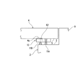
上記のように、必要に応じて短絡防止処理を施した後に、図15に示すように、溝7に第一モルタル(グラウト材)115を所定の厚みになるよう充填する。第一モルタル115は、セメントに細骨材と水のみを配合したものである。充填の際は、第一モルタル115をある程度の量だけ収容し得るモルタル注入具Mを用いて、溝7の奥(溝底面)まで充填する。そして、第一モルタル115が硬化しないうちに、図16および図17に示すように、陽極95を溝7に挿入する。   As described above, after performing the short-circuit prevention treatment as necessary, as shown in FIG. 15, the groove 7 is filled with the first mortar (grouting material) 115 to a predetermined thickness. The first mortar 115 is a mixture of fine aggregate and water only in cement. At the time of filling, the depth of the groove 7 (groove bottom surface) is filled using a mortar injection tool M that can accommodate the first mortar 115 in a certain amount. Then, before the first mortar 115 is cured, the anode 95 is inserted into the groove 7 as shown in FIGS.

ここで、陽極95は、網目を有する長尺帯状の金属体から構成され、該金属体が幅方向(短手方向)中心で折り曲げられた形状である。このように折り曲げた状態の陽極95の幅は、溝7の幅に比べて大きく設定されている。なお、網目は陽極95をエキスパンドメタル状に加工する際の延伸時に形成された菱形状である。   Here, the anode 95 is composed of a long band-shaped metal body having a mesh, and the metal body is bent at the center in the width direction (short direction). The width of the anode 95 in the bent state is set larger than the width of the groove 7. The mesh has a rhombus shape formed during stretching when the anode 95 is processed into an expanded metal shape.

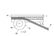
陽極95を、第一モルタル115を充填した溝7に装着するには、前述の溝形成部12において切削刃62を取り外し、図16および図17に示す電極押圧体99に取り替えた溝形成部12(図16、図17では、電極押圧体99のみを記載している)を利用して行うことができる。電極押圧体99は回転中心部に、中心孔99aが形成された円盤状に形成されている。電極押圧体99の外周部106は、刃厚の中心部が最も径方向外方になるよう(最大径になるよう)、厚み方向両側が厚み方向中心へ向かって傾斜する傾斜面によって形成されて外周尖端部となっている。この電極押圧体99の径は、切削刃62に比べてわずかに小さく設定されている。   In order to mount the anode 95 in the groove 7 filled with the first mortar 115, the cutting blade 62 is removed from the groove forming part 12 described above, and the groove forming part 12 is replaced with the electrode pressing body 99 shown in FIGS. (In FIG. 16, FIG. 17, only the electrode pressing body 99 is described). The electrode pressing body 99 is formed in a disk shape with a center hole 99a formed at the center of rotation. The outer peripheral portion 106 of the electrode pressing body 99 is formed by an inclined surface in which both sides in the thickness direction are inclined toward the center in the thickness direction so that the center portion of the blade thickness is radially outward (maximum diameter). It is the outer peripheral tip. The diameter of the electrode pressing body 99 is set slightly smaller than that of the cutting blade 62.

陽極95を、その折曲げ部分が上方になるようにして溝7に対して後方から前方へ向けてある程度の長さだけ挿入した状態で、上述の(3)〜(5)で示した作業を行い、続いて(7)で示した作業を行う。そうすると、電極押圧体99の外周尖端部が陽極95の折曲げ部分に挿入されて、陽極95がその長手方向に順次上方(溝底面側)へ押圧される。第一モルタル115は細骨材のみを配合しているから、陽極95の菱形の網目の間に第一モルタル115が入り込んで、第一モルタル115の保持力と、溝7の幅に比べて大きい幅を有する陽極95を溝7に挿入することによる陽極95そのものの横方向への弾性力とにより、陽極95を溝7から落下させることなく保持できる。   With the anode 95 inserted into the groove 7 in a certain length from the rear to the front with the bent portion facing upward, the operations shown in the above (3) to (5) are performed. Then, the operation shown in (7) is performed. Then, the outer peripheral tip of the electrode pressing body 99 is inserted into the bent portion of the anode 95, and the anode 95 is sequentially pressed upward (in the groove bottom side) in the longitudinal direction. Since the first mortar 115 contains only fine aggregate, the first mortar 115 enters between the rhombic meshes of the anode 95 and is larger than the holding force of the first mortar 115 and the width of the groove 7. The anode 95 can be held without dropping from the groove 7 due to the lateral elastic force of the anode 95 itself by inserting the anode 95 having a width into the groove 7.

このような作業を、各溝7に対して行い、続いて図18に示すように、溝7の埋めきれていないスペースに第二モルタル116を、第一モルタル115の充填と同様にして充填する。この第二モルタル116は、第一モルタル115に配合した骨材に比べて粗い骨材を用いたモルタルであってもよいし、第一モルタル115と同じモルタルであってもよい。   Such an operation is performed on each groove 7 and then, as shown in FIG. 18, the second mortar 116 is filled in the unfilled space of the groove 7 in the same manner as the filling of the first mortar 115. . The second mortar 116 may be a mortar using a coarser aggregate than the aggregate blended in the first mortar 115 or the same mortar as the first mortar 115.

また、陽極設置作業としては、全ての溝7を予め形成し、各溝7に対して、第一モルタル115の充填、陽極95の設置、第二モルタル116の充填を順に行うものであるが、溝7を形成するごとに第一モルタル115の充填、陽極95の設置、第二モルタル116の充填を行ってもよいし、全ての溝7に対して順次第一モルタル115を充填した後、全ての溝7に対して順次陽極95を設置し、さらにその後に全ての溝7に対して順次第二モルタル116を充填してもよい。これの手順の選択は、作業環境によって任意に選択し得る。   In addition, as the anode installation work, all the grooves 7 are formed in advance, and the filling of the first mortar 115, the installation of the anode 95, and the filling of the second mortar 116 are sequentially performed for each groove 7. Each time the groove 7 is formed, the first mortar 115 may be filled, the anode 95 may be installed, and the second mortar 116 may be filled. The anodes 95 may be sequentially installed in the grooves 7, and then the second mortar 116 may be sequentially filled in all the grooves 7. The selection of the procedure can be arbitrarily selected according to the work environment.

以上のように、本発明の実施形態の切削装置1は、押圧手段としてのジャッキ11A,11Bを用いてレール体10を上昇させ、その押圧力でもってレール体10の天板部13の上面20を溝形成面としての橋桁4の裏面5に押し当てて、レール体10を位置決め固定し、しかもその押圧力によって切削刃62を溝形成面に押圧する(押し当てる)ことのできる構成である。このように、レール体10を固定する手段と、切削刃62を溝形成面に押圧する手段とを別個に設けることなく、押圧手段11A,11Bで兼用している構成によれば、その分だけ切削装置1の構成を簡素化することができ、小型化することができる。   As described above, the cutting apparatus 1 according to the embodiment of the present invention raises the rail body 10 using the jacks 11A and 11B as pressing means, and the upper surface 20 of the top plate portion 13 of the rail body 10 with the pressing force. Is pressed against the back surface 5 of the bridge girder 4 as a groove forming surface, the rail body 10 is positioned and fixed, and the cutting blade 62 can be pressed (pressed) against the groove forming surface by the pressing force. As described above, according to the configuration in which the pressing means 11A and 11B are used together without separately providing the means for fixing the rail body 10 and the means for pressing the cutting blade 62 against the groove forming surface, only that much. The configuration of the cutting device 1 can be simplified and the size can be reduced.

さらに、切削装置1は、溝形成部12のうち切削刃62の外周部87のみをレール体10から露出させて、他の部分はレール体10の内部(溝形成部収容空間)に収納するような形態であるから、その分だけ切削装置1全体の高さが嵩むのを抑えることができ、高さの低い狭隘なスペースにも極めて有効に用いることができる。   Further, the cutting device 1 exposes only the outer peripheral portion 87 of the cutting blade 62 of the groove forming portion 12 from the rail body 10 and stores the other portion in the rail body 10 (groove forming portion receiving space). Therefore, it is possible to suppress the height of the entire cutting apparatus 1 from being increased by that much, and it can be used extremely effectively in a narrow space with a low height.

したがって、橋台2の天端面3と橋桁4の裏面5とで形成される空間スペース6のような、作業者が進入することが不可能な狭隘な空間において、コンクリート構造物内部に配置された鉄筋の腐食防止のために、陽極95を埋設する溝7を裏面5に形成するにあたり、例えば橋台2の天端面3を、作業スペースを確保すべく大きくはつる作業を要することなく、空間スペース6の形状を保持したまま、溝7を形成することができる。このように、作業者のはつり作業を省略することができることによれば、溝形成の施工が極めて楽になる。   Therefore, in a narrow space where an operator cannot enter, such as a space 6 formed by the top end surface 3 of the abutment 2 and the back surface 5 of the bridge girder 4, the reinforcing bars arranged inside the concrete structure In order to prevent corrosion, the groove 7 in which the anode 95 is embedded is formed on the back surface 5. For example, the top end surface 3 of the abutment 2 is not required to be hung to secure a work space. The groove 7 can be formed while maintaining the shape. Thus, according to the fact that the operator can omit the lifting work, the construction of the groove formation becomes extremely easy.

ところで、上記実施形態では、切削装置1を用いて溝7を形成した後に陽極95を溝7に装着するにあたり、溝形成部12を利用する場合を説明した。しかしながら、切削装置1を用いて溝7を形成した後に、陽極95を溝7に装着するにあたり、独自の装置である電極設置装置を用いてもよい。ここで、図19〜図22に基づいて、陽極95を溝7に設置するための電極設置装置96について説明する。電極設置装置96は、既に説明したレール体10と、レール体10に沿って前後方向に移動可能な電極設置部97とから構成される。レール体10の構成は前述のとおりであるのでその説明を省略し、以下に電極設置部97の説明をする。   By the way, in the said embodiment, when forming the groove | channel 7 using the cutting device 1 and attaching the anode 95 to the groove | channel 7, the case where the groove | channel formation part 12 was utilized was demonstrated. However, when the groove 7 is formed using the cutting device 1 and the anode 95 is attached to the groove 7, an electrode installation device that is a unique device may be used. Here, based on FIGS. 19-22, the electrode installation apparatus 96 for installing the anode 95 in the groove | channel 7 is demonstrated. The electrode installation device 96 includes the rail body 10 already described and an electrode installation portion 97 that can move in the front-rear direction along the rail body 10. Since the structure of the rail body 10 is as described above, the description thereof will be omitted, and the electrode installation portion 97 will be described below.

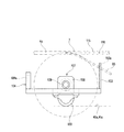
図示した電極設置部97は、台車(以下「第二台車」と称す)98と、電極押圧体99とを備えている。第二台車98は、レール体10に沿って溝形成方向に案内される、具体的には、案内レール15A,15Bの案内面40a,41aに沿って前後方向に移動可能な電極設置用被案内体であり、その左右幅は第一台車60と等しく設定されている。第二台車98は、キャスタ100(車輪)が取付けられる左右一対のキャスタ(車輪)取付け領域部101と、キャスタ(車輪)取付け領域部101の間に形成され、電極押圧体99が設置される設置領域部102とを有する板部材から形成されている。この第二台車98を構成する板部材は、左右方向中心に対する左右両側部分での重量バランス、および軽量化を考慮して、不要な部分を省いた形状に形成されている。特に、後述する電極支持壁103と押圧壁104との間の特定領域105は切欠かれている。   The illustrated electrode installation portion 97 includes a carriage (hereinafter referred to as “second carriage”) 98 and an electrode pressing body 99. The second carriage 98 is guided along the rail body 10 in the groove forming direction. Specifically, the second carriage 98 is guided for electrode installation that can move in the front-rear direction along the guide surfaces 40a and 41a of the guide rails 15A and 15B. The left and right widths of the body are set equal to those of the first carriage 60. The second carriage 98 is formed between a pair of left and right caster (wheel) attachment region 101 to which the caster 100 (wheel) is attached, and the caster (wheel) attachment region 101, and the electrode pressing body 99 is installed. It is formed from a plate member having a region portion 102. The plate member constituting the second carriage 98 is formed in a shape in which unnecessary portions are omitted in consideration of weight balance at the left and right side portions with respect to the center in the left-right direction and weight reduction. In particular, a specific region 105 between the electrode support wall 103 and the pressing wall 104 described later is cut away.

第二台車98の先端部(前端部)には、前記電極支持壁103が立設されている。電極支持壁103は、設置領域部102の前方突出部の先端部において上方に立ち上げて形成されており、上部の左右方向中心に、陽極95を前後方向に通すための挿通孔103aが形成されている。また、電極支持壁103は、第二台車98の左右幅に比べてかなり小さい幅に設定されており、第二台車98の左右幅中心に対して他方側に位置ずれして配置されている。よって、挿通孔103aも第二台車98の左右幅中心に対して他方側に位置ずれして配置されている。なお、挿通孔103aの第二台車98の左右方向中心からの位置ずれ量は、切削装置1における切削刃62の位置ずれ量と等しい。   The electrode support wall 103 is erected at the front end (front end) of the second carriage 98. The electrode support wall 103 is formed so as to rise upward at the front end portion of the front projecting portion of the installation region portion 102, and an insertion hole 103a for allowing the anode 95 to pass in the front-rear direction is formed at the center in the left-right direction. ing. In addition, the electrode support wall 103 is set to a width that is considerably smaller than the left and right width of the second carriage 98, and is disposed so as to be shifted to the other side with respect to the left and right width center of the second carriage 98. Therefore, the insertion hole 103a is also displaced from the center of the left and right width of the second carriage 98 on the other side. The amount of positional deviation of the insertion hole 103a from the center in the left-right direction of the second carriage 98 is equal to the amount of positional deviation of the cutting blade 62 in the cutting device 1.

第二台車98の後端部には、第二台車98を後方から前方へ向けて押圧するための前記押圧壁104が立設されている。押圧壁104は、第二台車98の左右幅と同一の幅に設定されており、上下高さは設置領域部102の上下高さよりも低く設定されている。また、押圧壁104には、押圧杆部材(図示せず)の先端部を取付けるための取付け孔104aが形成されている。取付け孔104aの左右方向位置は、第二台車98の左右幅中心に対して他方側に位置ずれして配置されており、その位置ずれ量は、設置領域部102の挿通孔103aの位置ずれ量と同じである。よって、取付け孔104aと挿通孔103aとは、左右方向の位置は対応した同じ位置にある。但し、取付け孔104aは、挿通孔103aに比べて上下方向では低い位置に形成されている。   At the rear end portion of the second carriage 98, the pressing wall 104 for pressing the second carriage 98 from the rear to the front is provided upright. The pressing wall 104 is set to have the same width as the left and right width of the second carriage 98, and the vertical height is set lower than the vertical height of the installation region portion 102. Further, the pressing wall 104 is formed with an attachment hole 104a for attaching a distal end portion of a pressing rod member (not shown). The position of the mounting hole 104a in the left-right direction is shifted to the other side with respect to the center of the left-right width of the second carriage 98, and the amount of position shift is the amount of position shift of the insertion hole 103a in the installation region portion 102. Is the same. Therefore, the mounting hole 104a and the insertion hole 103a are in the same position in the left-right direction. However, the mounting hole 104a is formed at a lower position in the vertical direction than the insertion hole 103a.

電極押圧体99は、図16および図17で説明したものと同一の構成である。すなわち、これらの図を参照して、電極押圧体99は、回転中心部に、中心孔99aが形成された円盤状に形成されている。中心孔99aの周面には、雌ねじが形成されている。電極押圧体99の外周部106は、刃厚の中心部が最も径方向外方にあるよう(最大径になるよう)、厚み方向両側が厚み方向中心へ向かって傾斜する傾斜面によって形成されて外周尖端部となっている。   The electrode pressing body 99 has the same configuration as that described with reference to FIGS. 16 and 17. That is, with reference to these drawings, the electrode pressing body 99 is formed in a disk shape in which a central hole 99a is formed at the center of rotation. An internal thread is formed on the peripheral surface of the center hole 99a. The outer peripheral portion 106 of the electrode pressing body 99 is formed by an inclined surface in which both sides in the thickness direction are inclined toward the center in the thickness direction so that the center portion of the blade thickness is the outermost in the radial direction (maximum diameter). It is the outer peripheral tip.

図21および図22に示すように、電極押圧体99は、電極支持壁103と押圧壁104との間に配置され、その略下半分が、電極支持壁103と押圧壁104との間の切欠かれた前記特定領域105から下方に突出するよう、支持手段107を介して第二台車98に取付けられている。そして電極押圧体99は、厚み方向中心が、挿通孔103aの左右方向の位置に一致するよう、第二台車98の左右方向中心に対して位置ずれした位置で、支持手段107に支持されている。電極押圧体99の上端部の高さ位置は、挿通孔103aに比べて高い位置にあるよう設定されている。   As shown in FIGS. 21 and 22, the electrode pressing body 99 is disposed between the electrode support wall 103 and the pressing wall 104, and a substantially lower half thereof is a notch between the electrode support wall 103 and the pressing wall 104. It is attached to the second carriage 98 via the support means 107 so as to protrude downward from the specified area 105. The electrode pressing body 99 is supported by the support means 107 at a position displaced from the center in the left-right direction of the second carriage 98 so that the center in the thickness direction coincides with the position in the left-right direction of the insertion hole 103a. . The height position of the upper end portion of the electrode pressing body 99 is set to be higher than the insertion hole 103a.

支持手段107は、電極支持壁103と押圧壁104との間の切欠かれた特定領域105の端面と面一となるよう第二台車98の上面に立設された支持片108と、支持片108を左右方向に貫通する支軸体109と、支軸体109の一方側端部を外嵌するブッシュ110とから構成されている。   The support means 107 includes a support piece 108 erected on the upper surface of the second carriage 98 so as to be flush with the end face of the specific region 105 notched between the electrode support wall 103 and the pressing wall 104, and the support piece 108. Is formed of a support shaft body 109 penetrating in the left-right direction and a bush 110 that externally fits one end portion of the support shaft body 109.

支軸体109は、左右方向に軸心が沿っており、他方側に雄ねじ109aが形成されるとともに、スナップ・リング112で支持片108から抜止めされている。電極押圧体99は、その中心孔99aが雄ねじに螺合することで、支軸体109に装着されている。電極押圧体99と支持片108との間に環状の緩衝部材113が介装されている。   The shaft body 109 has an axial center extending in the left-right direction, a male screw 109a is formed on the other side, and is secured from the support piece 108 by a snap ring 112. The electrode pressing body 99 is attached to the support shaft body 109 by the center hole 99a being screwed into the male screw. An annular buffer member 113 is interposed between the electrode pressing body 99 and the support piece 108.

キャスタ(車輪)100は、第二台車98の裏面から下方に突出しており、左右のキャスタ(車輪)取付け領域部101にそれぞれ設けられて、左右方向に離間して一対で配置されている。また、これらキャスタ100は、第二台車の裏面に、前後方向においては同位置に配置されている。   The casters (wheels) 100 protrude downward from the back surface of the second carriage 98, are provided in the left and right caster (wheel) attachment region portions 101, and are arranged in pairs in the left-right direction. These casters 100 are disposed on the back surface of the second carriage at the same position in the front-rear direction.

このような構成の電極設置部97は、レール体10に装着して用いられる。電極設置部97は、電極押圧体99が天板部13の切削刃突出用空間19から上方に突出した状態で、天板部13の下側において胴部14で形成される溝形成部収容空間(この場合、電極設置部収容空間)に収容されて案内レール15A,15Bに保持されている。具体的には、電極設置部97は、キャスタ100を案内レール15A,15Bの案内面40a,41aに載置するようにして、案内レール15A,15Bの間に挿入することで装着される。   The electrode installation portion 97 having such a configuration is used by being mounted on the rail body 10. The electrode installation portion 97 is a groove forming portion accommodation space formed by the body portion 14 below the top plate portion 13 in a state where the electrode pressing body 99 protrudes upward from the cutting blade protruding space 19 of the top plate portion 13. (In this case, it is accommodated in the electrode installation portion accommodating space) and is held by the guide rails 15A and 15B. Specifically, the electrode installation portion 97 is mounted by inserting the caster 100 between the guide rails 15A and 15B so that the caster 100 is placed on the guide surfaces 40a and 41a of the guide rails 15A and 15B.

電極設置部97を用いて陽極95を溝7に設置する場合では、既に溝7は形成済であるから、レール体10は予め空間スペース6に挿入して橋台2の天端面3と橋桁4の裏面5との間に概ね設置しておいてよい。但し、電極設置部97の電極押圧体99を溝7に位置合わせする必要があるから、レール体10に電極設置部97を装着した後での、レール体10の左右方向の微調整は、適宜必要である。   When the anode 95 is installed in the groove 7 using the electrode installation portion 97, the groove 7 has already been formed. Therefore, the rail body 10 is inserted into the space 6 in advance and the top end surface 3 of the abutment 2 and the bridge beam 4 are You may install in general between the back surfaces 5. However, since it is necessary to align the electrode pressing body 99 of the electrode installation portion 97 with the groove 7, fine adjustment in the left-right direction of the rail body 10 after the electrode installation portion 97 is mounted on the rail body 10 is appropriately performed. is necessary.

電極設置部97をレール体10に装着する際には、図22に示すように、予め電極支持壁103の挿通孔103aに、その前方から後方へ向けて陽極95を挿通しておき、電極押圧体99の上端部まで引込んでおく(導入しておく)。また、陽極95は、電極押圧体99の外周尖端部が折曲げ部に挿入されるよう保持しておく。そして、電極押圧体99を溝7に位置合わせし、ジャッキを伸長させて天板部13の上面20を橋桁4の裏面5に圧接したら、ジャッキの伸長(押し上げ)によって電極押圧体99の上端部が溝7内に入り込み、電極押圧体99の上端部にある陽極95の後端部が溝7への陽極95の装着のスタート地点に押し込まれた状態となるので、電極設置部97をレール体10に沿って前方へ押し込む。   When the electrode installation portion 97 is attached to the rail body 10, as shown in FIG. 22, the anode 95 is inserted through the insertion hole 103a of the electrode support wall 103 from the front to the rear in advance, The upper end of the body 99 is retracted (introduced). The anode 95 is held so that the outer peripheral tip of the electrode pressing body 99 is inserted into the bent portion. Then, when the electrode pressing body 99 is aligned with the groove 7 and the jack is extended so that the upper surface 20 of the top plate portion 13 is pressed against the back surface 5 of the bridge girder 4, the upper end of the electrode pressing body 99 is extended (pushing up). Enters the groove 7, and the rear end of the anode 95 at the upper end of the electrode pressing body 99 is pushed into the starting point of the mounting of the anode 95 in the groove 7. Push forward along 10.

このとき、作業者が直接的に電極設置部97を押し込んでもよいが、押圧壁104の取付け孔104aに、押圧杆部材の先端部を取付けて、該押圧杆部材を押すことで電極設置部97を容易に押し込むことができる。電極設置部97を押し込む移動に伴って、陽極95が、溝7の奥側(第一モルタル115)に押圧され、第一モルタル115と電極押圧体99の外周尖端部とで挟持(保持)されて、その挟持力により電極押圧体99が支軸体109回りに回転し、支軸体109の回転に伴って陽極95が挿通孔103aから順次引き込まれ、陽極95が順次溝7に装着される。   At this time, the operator may directly press the electrode installation part 97, but the electrode installation part 97 is attached by attaching the tip of the pressing rod member to the mounting hole 104a of the pressing wall 104 and pressing the pressing rod member. Can be pushed in easily. As the electrode installation portion 97 is pushed in, the anode 95 is pressed to the back side (first mortar 115) of the groove 7, and is held (held) between the first mortar 115 and the tip of the outer periphery of the electrode pressing body 99. Thus, the electrode pressing body 99 is rotated around the support shaft body 109 by the clamping force, and the anode 95 is sequentially drawn from the insertion hole 103 a as the support shaft body 109 rotates, and the anode 95 is sequentially mounted in the groove 7. .

一本の溝7について陽極95の装着が終了すれば、予め第一モルタル115が充填されている次の溝7に電極押圧体99を位置合わせするようにレール体10を移動させ、上記と同様の作業により、溝7ごとに陽極95を設置する。そして、溝7において陽極95の設置が終了したものから、第二モルタル116を溝7に充填して、電極設置作業を終了する。   When the mounting of the anode 95 for one groove 7 is completed, the rail body 10 is moved so as to align the electrode pressing body 99 with the next groove 7 filled with the first mortar 115 in advance. Through the above operation, the anode 95 is installed for each groove 7. Then, after the installation of the anode 95 in the groove 7 is completed, the second mortar 116 is filled in the groove 7 and the electrode installation work is completed.

レール体10を利用し、電極設置部97を用いて陽極95を溝7に設置する作業では、狭隘部において作業者が狭隘部に腕を挿入して陽極95を設置する必要がないので、陽極95の設置作業を極めて楽に、しかも効率良く行うことができる。   In the operation of using the rail body 10 and installing the anode 95 in the groove 7 using the electrode installation portion 97, it is not necessary for the operator to install the anode 95 by inserting an arm into the narrow portion in the narrow portion. 95 can be installed very easily and efficiently.

このように、電極設置部97は溝7に沿って移動可能な第二台車98と、溝形成方向に直交し溝形成面である裏面5に沿う軸心回りに回転可能な状態で第二台車98に取付けられた円盤状の電極押圧体99と、電極押圧体99の外周部に陽極95を導入案内する案内部としての電極支持壁103を備えている。そして、第二台車98を溝形成方向に移動させることで、電極押圧体99の外周部が、第二台車98の溝形成方向への移動に伴って、溝7に位置合わせされた陽極95を溝底面側に押圧しつつ、溝7に陽極95を設置することができる。   Thus, the electrode installation part 97 is movable in the groove 7 along the second carriage 98, and the second carriage in a state of being rotatable about the axis along the back surface 5 that is perpendicular to the groove forming direction and is the groove forming surface. A disk-shaped electrode pressing body 99 attached to 98 and an electrode support wall 103 as a guide portion for introducing and guiding the anode 95 to the outer peripheral portion of the electrode pressing body 99 are provided. Then, by moving the second carriage 98 in the groove forming direction, the outer peripheral portion of the electrode pressing body 99 moves the anode 95 aligned with the groove 7 as the second carriage 98 moves in the groove forming direction. The anode 95 can be installed in the groove 7 while pressing toward the groove bottom side.

上記実施形態では、陽極95を設置するための溝7を、橋台2の天端面3と橋桁4の裏面5の関係で形成される狭隘な空間スペース6において、橋桁4の裏面5に形成する場合で説明した。しかしながら、橋台2の他に、橋桁4が支持される橋脚の天端面と橋桁4の裏面5の関係で形成される狭隘な空間スペース6において、橋桁4の裏面5に溝7を形成する場合であっても、切削装置1を上記実施形態と同様にして使用することができる。この場合の前後方向の設定は、橋桁4の軸心に沿う方向であれば、両桁端のうち何れの桁端側を前としてもよい。電極設置装置96もまた、橋台2の他に、橋桁4が支持される橋脚の天端面と橋桁4の裏面5の関係で形成される狭隘な空間スペース6において橋桁4の裏面5に形成した溝7に陽極95を設置する場合に、上記実施形態と同様にして用いることができる。   In the above embodiment, the groove 7 for installing the anode 95 is formed in the back surface 5 of the bridge girder 4 in the narrow space 6 formed by the relationship between the top end surface 3 of the abutment 2 and the back surface 5 of the bridge girder 4. Explained. However, in addition to the abutment 2, the groove 7 is formed on the back surface 5 of the bridge girder 4 in the narrow space 6 formed by the relationship between the top end surface of the pier supporting the bridge girder 4 and the back surface 5 of the bridge girder 4. Even if it exists, the cutting device 1 can be used similarly to the said embodiment. In this case, as long as the setting in the front-rear direction is along the axial center of the bridge girder 4, any girder end of both girder ends may be the front. In addition to the abutment 2, the electrode installation device 96 also has a groove formed in the back surface 5 of the bridge girder 4 in a narrow space 6 formed by the relationship between the top end surface of the pier on which the bridge girder 4 is supported and the back surface 5 of the bridge girder 4. 7 can be used in the same manner as in the above embodiment.

上記実施形態では、橋桁4の裏面5に溝7を形成する場合で説明した。しかしながら、切削装置1は、狭隘な空間スペース6において橋台2の天端面3に溝7を形成することもできる。この場合では、レール体10および溝形成部12を上下逆転させるようにして用い、押圧手段11A,11Bの下部50,51を橋桁4の裏面5に押圧するようにして、天板部13の上面20を橋台2の天端面3に圧接して、レール体10を空間スペース6内に装着する。電極設置装置96もまた、レール体10および電極設置部97を上下逆転させるようにして用いることで、狭隘な空間スペース6において橋台2の天端面3に形成した溝7に陽極95を設置することができる。   In the said embodiment, it demonstrated by the case where the groove | channel 7 was formed in the back surface 5 of the bridge girder 4. FIG. However, the cutting device 1 can also form the grooves 7 in the top end surface 3 of the abutment 2 in a narrow space 6. In this case, the rail body 10 and the groove forming portion 12 are used so as to be reversed upside down, and the lower portions 50 and 51 of the pressing means 11A and 11B are pressed against the back surface 5 of the bridge girder 4 to 20 is pressed against the top end surface 3 of the abutment 2, and the rail body 10 is mounted in the space 6. The electrode installation device 96 also uses the rail body 10 and the electrode installation portion 97 so as to be turned upside down, so that the anode 95 is installed in the groove 7 formed in the top end surface 3 of the abutment 2 in the narrow space 6. Can do.

上記実施形態では、切削装置1は、狭隘部で用いる場合で説明した。しかしながら、切削装置1は狭隘部での空間スペース6のみに用いることに限定されず、切削装置1を上下に対向した面の間に固定可能であれば、狭隘部でなくとも、その対向した面に溝7を形成することができる。また、狭隘部での空間スペース6、あるいは狭隘部ではない空間スペース6における、横方向(水平方向)や縦方向で対向する面に溝7を形成するのに用いることも可能である。   In the said embodiment, the cutting device 1 demonstrated by the case where it uses in a narrow part. However, the cutting device 1 is not limited to being used only for the space 6 in the narrow portion, and if the cutting device 1 can be fixed between the vertically opposed surfaces, the facing surface is not limited to the narrow portion. A groove 7 can be formed in the groove. Further, it can be used to form the groove 7 on the surface facing in the horizontal direction (horizontal direction) or the vertical direction in the space space 6 in the narrow portion or in the space space 6 that is not the narrow portion.

電極設置装置96も同様であり、狭隘部での空間スペース6のみに用いる場合に限定されず、電極設置装置96を上下に対向した面の間に固定可能であれば、狭隘部でなくとも、その対向した面に形成した溝7に陽極95を設置することができる。また、狭隘部での空間スペース6、あるいは狭隘部ではない空間スペース6における、横方向(水平方向)や縦方向で対向する面に形成した溝7に陽極95を設置することも可能である。   The electrode installation device 96 is the same, and is not limited to the case where the electrode installation device 96 is used only in the space 6 in the narrow portion, and if the electrode installation device 96 can be fixed between the vertically opposed surfaces, An anode 95 can be installed in the groove 7 formed on the facing surface. It is also possible to install the anode 95 in the groove 7 formed on the surface facing in the horizontal direction (horizontal direction) or the vertical direction in the space space 6 in the narrow portion or in the space space 6 not in the narrow portion.

上記実施形態では、レール体10を空間スペース6に挿入する際、対向する面のうちの一方の面(例えば天端面3)に、直に載置した。しかしながら、例えば、レール体10の下部に車輪(図示せず)を取付けておき、レール体10を空間スペース6に挿入する際に、該車輪によって案内させるよう構成することもできる。車輪の設置場所としては特に限定されないが、レール体10全体のコンパクト化といった観点から、レール体10に対する車輪の突出量はできるだけ少なくなるようにすることが好ましく、レール体10の下部に車輪を取付けることにより、レール体10を空間スペース6内に、円滑且つ楽に挿入することができる。   In the said embodiment, when inserting the rail body 10 in the space space 6, it mounted directly on one surface (for example, top end surface 3) of the opposing surfaces. However, for example, a wheel (not shown) may be attached to the lower portion of the rail body 10, and the rail body 10 may be guided by the wheel when the rail body 10 is inserted into the space 6. Although the installation location of the wheel is not particularly limited, it is preferable that the protruding amount of the wheel with respect to the rail body 10 is as small as possible from the viewpoint of making the rail body 10 compact, and the wheel is attached to the lower part of the rail body 10. As a result, the rail body 10 can be smoothly and easily inserted into the space 6.

なお、上記実施形態では、コンクリート構造物の表面部に溝を形成する装置として切削装置1を説明したが、コンクリート構造物以外の、木材、石材による構造物の表面部に、電極(陽極)設置以外の目的の溝を形成する場合にも適用することが可能である。   In the above embodiment, the cutting apparatus 1 has been described as an apparatus for forming a groove in the surface portion of a concrete structure. However, an electrode (anode) is installed on the surface portion of a structure made of wood or stone other than the concrete structure. The present invention can also be applied to the case of forming a groove other than the purpose.

1…切削装置、2…橋台、3…天端面、4…橋桁、4a…予堀、5…裏面、6…空間スペース、7…溝、10…レール体、11A,11B…押圧手段、12…溝形成部、13…天板部、15A,15B…案内レール、19…切削刃突出用空間、31,32…板部材、40,41…下壁、40a,41a…案内面、60…第一台車、60a,60a…側端面、60c…前面、61…駆動モータ部、62…切削刃、63a…前端面、65A,65B…キャスタ、66…切欠部、72a…駆動軸心、73…固定手段、74…突出部、75…軸部材、76…緩衝体、77…ベルト、84…回転軸、88…傾斜面、89…第一保持穴、90…第二保持穴、95…陽極、97…電極設置部、98…第二台車、99…電極押圧体、103…電極支持壁、103a…挿通孔、115…第一モルタル、116第二モルタル   DESCRIPTION OF SYMBOLS 1 ... Cutting device, 2 ... Abutment, 3 ... Top end surface, 4 ... Bridge girder, 4a ... Pre-drilling, 5 ... Back surface, 6 ... Spatial space, 7 ... Groove, 10 ... Rail body, 11A, 11B ... Pressing means, 12 ... Groove forming portion, 13 ... top plate portion, 15A, 15B ... guide rail, 19 ... space for projecting cutting blade, 31,32 ... plate member, 40,41 ... lower wall, 40a, 41a ... guide surface, 60 ... first Cart, 60a, 60a ... side end face, 60c ... front face, 61 ... drive motor section, 62 ... cutting blade, 63a ... front end face, 65A, 65B ... casters, 66 ... notch, 72a ... drive shaft, 73 ... fixing means 74 ... Projection, 75 ... Shaft member, 76 ... Buffer, 77 ... Belt, 84 ... Rotating shaft, 88 ... Inclined surface, 89 ... First holding hole, 90 ... Second holding hole, 95 ... Anode, 97 ... Electrode installation portion, 98 ... second carriage, 99 ... electrode pressing body, 103 ... electrode support wall, 10 a ... insertion holes, 115 ... first mortar, 116 second mortar

Claims (3)

互いに対向する一対の対向面のうちの一方の対向面に、所定長さの溝を形成するための切削装置であって、
前記対向面の間に挿入されるレール体と、溝形成方向と直交するよう対向面と平行な支軸回りに回転駆動する切削刃を備えて、該切削刃を前記レール体に沿って溝形成方向に案内する溝形成部と、前記一方の対向面側に向けてレール体を押すための押圧手段とが設けられ、
前記レール体は前記押圧手段で一方の対向面側に押されることで該一方の対向面に当接する当接部を備え、
前記溝形成部は、前記切削刃の外周部が前記当接部に対して一方の対向面側に突出した状態で、レール体が押圧手段で押されて一方の対向面側へ向けて移動するのに伴ってレール体とともに一方の対向面側へ向けて移動するようレール体に保持されている、ことを特徴とする切削装置。
A cutting device for forming a groove of a predetermined length on one of the pair of opposed surfaces facing each other,
A rail body inserted between the facing surfaces, and a cutting blade that is driven to rotate around a spindle parallel to the facing surface so as to be orthogonal to the groove forming direction, the cutting blade is formed along the rail body. A groove forming portion that guides in the direction, and a pressing means for pressing the rail body toward the one opposing surface,
The rail body includes an abutting portion that abuts against the one opposing surface by being pressed toward the one opposing surface by the pressing means,
The groove forming portion moves toward the one opposing surface side when the rail body is pressed by the pressing means in a state where the outer peripheral portion of the cutting blade protrudes toward the one opposing surface side with respect to the contact portion. Accordingly, the cutting device is held by the rail body so as to move toward the one facing surface side together with the rail body.
当接部は切削刃に対して支軸の軸線方向の両側に配置され、レール体は、前記当接部に対して他方の対向面側に離間して配置されて溝形成部を溝形成方向に案内する案内面を備え、
溝形成部は当接部と案内面との間に保持されていることを特徴とする請求項1記載の切削装置。
The abutting portions are arranged on both sides in the axial direction of the support shaft with respect to the cutting blade, and the rail body is arranged apart from the abutting portion on the other facing surface side, and the groove forming portion is arranged in the groove forming direction. With a guide surface to guide
The cutting apparatus according to claim 1, wherein the groove forming portion is held between the contact portion and the guide surface.
切削刃は溝形成部に備えた駆動モータにより駆動される構成であり、溝形成部は前記駆動モータがその長手方向を溝形成方向に沿うようレール体に保持されていることを特徴とする請求項1または請求項2記載の切削装置。   The cutting blade is configured to be driven by a drive motor provided in a groove forming portion, and the groove forming portion is held by a rail body so that the drive motor follows a longitudinal direction of the drive motor along the groove forming direction. The cutting device according to claim 1 or 2.
JP2011078941A 2011-03-31 2011-03-31 Cutting equipment Active JP4783480B1 (en)

Priority Applications (1)

Application Number Priority Date Filing Date Title
JP2011078941A JP4783480B1 (en) 2011-03-31 2011-03-31 Cutting equipment

Applications Claiming Priority (1)

Application Number Priority Date Filing Date Title
JP2011078941A JP4783480B1 (en) 2011-03-31 2011-03-31 Cutting equipment

Publications (2)

Publication Number Publication Date
JP4783480B1 true JP4783480B1 (en) 2011-09-28
JP2012214971A JP2012214971A (en) 2012-11-08

Family

ID=44798119

Family Applications (1)

Application Number Title Priority Date Filing Date
JP2011078941A Active JP4783480B1 (en) 2011-03-31 2011-03-31 Cutting equipment

Country Status (1)

Country Link
JP (1) JP4783480B1 (en)

Cited By (1)

* Cited by examiner, † Cited by third party
Publication number Priority date Publication date Assignee Title
CN106695001A (en) * 2017-02-16 2017-05-24 北京金风科创风电设备有限公司 Slot forming device for blade, blade assembly and processing method for blade

Families Citing this family (1)

* Cited by examiner, † Cited by third party
Publication number Priority date Publication date Assignee Title
JP5985407B2 (en) * 2013-02-06 2016-09-06 三井住友建設株式会社 Reinforcing method for existing concrete structures

Citations (2)

* Cited by examiner, † Cited by third party
Publication number Priority date Publication date Assignee Title
JPH0312106U (en) * 1989-06-21 1991-02-07
JP2006192677A (en) * 2005-01-13 2006-07-27 J P Ii Kk U-shaped groove-cutting apparatus

Patent Citations (2)

* Cited by examiner, † Cited by third party
Publication number Priority date Publication date Assignee Title
JPH0312106U (en) * 1989-06-21 1991-02-07
JP2006192677A (en) * 2005-01-13 2006-07-27 J P Ii Kk U-shaped groove-cutting apparatus

Cited By (2)

* Cited by examiner, † Cited by third party
Publication number Priority date Publication date Assignee Title
CN106695001A (en) * 2017-02-16 2017-05-24 北京金风科创风电设备有限公司 Slot forming device for blade, blade assembly and processing method for blade
CN106695001B (en) * 2017-02-16 2018-08-14 北京金风科创风电设备有限公司 Slot forming device for blade, blade assembly and processing method for blade

Also Published As

Publication number Publication date
JP2012214971A (en) 2012-11-08

Similar Documents

Publication Publication Date Title
JP4825935B1 (en) Cutting equipment
JP5276842B2 (en) Free sliding drill
JP4783480B1 (en) Cutting equipment
JP5584812B1 (en) Tilt repair device
JP4904435B1 (en) Electrode installation device
JP5695954B2 (en) Method of burying electrodes for cathodic protection
JP5695953B2 (en) Short circuit prevention method in cathodic protection method
JP4988051B1 (en) Groove forming method and electrode installation method in concrete structure
JP6169739B1 (en) Tilt repair device
JP4739939B2 (en) Telephone pole cutting machine
JP5690456B1 (en) Upper and lower pile welding equipment
JP3210871U (en) Base plate installation jig
KR100912647B1 (en) Cutting apparatus for heavy equipment
JP5102654B2 (en) Tunnel construction method
KR200317062Y1 (en) An excavator head for using back hoe
JP2010196455A (en) Vibrating pile driving and drawing machine
CN218253922U (en) Drilling machine clamping device that excavator accessories used
JP3889677B2 (en) Pile or pillar cutting device
CN219327505U (en) Perforating device is used in hydraulic engineering construction
CN113771235B (en) Multilateral rope saw cutting machine
JP2916681B1 (en) Treading device and treading work vehicle
JP2007262677A (en) Self-propelling apparatus of full slewing machine
CN107762431B (en) Underground drilling machine, dust collecting head device and assembly thereof, and dust collecting method
JP4955478B2 (en) Pile ground improvement system
JPH0853993A (en) Underground buried pipe laying device

Legal Events

Date Code Title Description
TRDD Decision of grant or rejection written
A01 Written decision to grant a patent or to grant a registration (utility model)

Free format text: JAPANESE INTERMEDIATE CODE: A01

Effective date: 20110610

A01 Written decision to grant a patent or to grant a registration (utility model)

Free format text: JAPANESE INTERMEDIATE CODE: A01

A61 First payment of annual fees (during grant procedure)

Free format text: JAPANESE INTERMEDIATE CODE: A61

Effective date: 20110708

FPAY Renewal fee payment (event date is renewal date of database)

Free format text: PAYMENT UNTIL: 20140715

Year of fee payment: 3

R150 Certificate of patent or registration of utility model

Ref document number: 4783480

Country of ref document: JP

Free format text: JAPANESE INTERMEDIATE CODE: R150

Free format text: JAPANESE INTERMEDIATE CODE: R150

R250 Receipt of annual fees

Free format text: JAPANESE INTERMEDIATE CODE: R250

R250 Receipt of annual fees

Free format text: JAPANESE INTERMEDIATE CODE: R250

R250 Receipt of annual fees

Free format text: JAPANESE INTERMEDIATE CODE: R250

R250 Receipt of annual fees

Free format text: JAPANESE INTERMEDIATE CODE: R250

R250 Receipt of annual fees

Free format text: JAPANESE INTERMEDIATE CODE: R250

R250 Receipt of annual fees

Free format text: JAPANESE INTERMEDIATE CODE: R250

R250 Receipt of annual fees

Free format text: JAPANESE INTERMEDIATE CODE: R250

R250 Receipt of annual fees

Free format text: JAPANESE INTERMEDIATE CODE: R250

R250 Receipt of annual fees

Free format text: JAPANESE INTERMEDIATE CODE: R250

S531 Written request for registration of change of domicile

Free format text: JAPANESE INTERMEDIATE CODE: R313531

R350 Written notification of registration of transfer

Free format text: JAPANESE INTERMEDIATE CODE: R350

R250 Receipt of annual fees

Free format text: JAPANESE INTERMEDIATE CODE: R250