JP4782992B2 - Endoscope device - Google Patents
Endoscope device Download PDFInfo
- Publication number
- JP4782992B2 JP4782992B2 JP2004209849A JP2004209849A JP4782992B2 JP 4782992 B2 JP4782992 B2 JP 4782992B2 JP 2004209849 A JP2004209849 A JP 2004209849A JP 2004209849 A JP2004209849 A JP 2004209849A JP 4782992 B2 JP4782992 B2 JP 4782992B2
- Authority
- JP
- Japan
- Prior art keywords
- illumination window
- light
- excitation light
- endoscope apparatus
- insertion portion
- Prior art date
- Legal status (The legal status is an assumption and is not a legal conclusion. Google has not performed a legal analysis and makes no representation as to the accuracy of the status listed.)
- Expired - Fee Related
Links
Images


Classifications
-
- A—HUMAN NECESSITIES
- A61—MEDICAL OR VETERINARY SCIENCE; HYGIENE
- A61B—DIAGNOSIS; SURGERY; IDENTIFICATION
- A61B1/00—Instruments for performing medical examinations of the interior of cavities or tubes of the body by visual or photographical inspection, e.g. endoscopes; Illuminating arrangements therefor
- A61B1/06—Instruments for performing medical examinations of the interior of cavities or tubes of the body by visual or photographical inspection, e.g. endoscopes; Illuminating arrangements therefor with illuminating arrangements
- A61B1/0653—Instruments for performing medical examinations of the interior of cavities or tubes of the body by visual or photographical inspection, e.g. endoscopes; Illuminating arrangements therefor with illuminating arrangements with wavelength conversion
-
- A—HUMAN NECESSITIES
- A61—MEDICAL OR VETERINARY SCIENCE; HYGIENE
- A61B—DIAGNOSIS; SURGERY; IDENTIFICATION
- A61B1/00—Instruments for performing medical examinations of the interior of cavities or tubes of the body by visual or photographical inspection, e.g. endoscopes; Illuminating arrangements therefor
- A61B1/06—Instruments for performing medical examinations of the interior of cavities or tubes of the body by visual or photographical inspection, e.g. endoscopes; Illuminating arrangements therefor with illuminating arrangements
- A61B1/0661—Endoscope light sources
- A61B1/0676—Endoscope light sources at distal tip of an endoscope
-
- A—HUMAN NECESSITIES
- A61—MEDICAL OR VETERINARY SCIENCE; HYGIENE
- A61B—DIAGNOSIS; SURGERY; IDENTIFICATION
- A61B1/00—Instruments for performing medical examinations of the interior of cavities or tubes of the body by visual or photographical inspection, e.g. endoscopes; Illuminating arrangements therefor
- A61B1/06—Instruments for performing medical examinations of the interior of cavities or tubes of the body by visual or photographical inspection, e.g. endoscopes; Illuminating arrangements therefor with illuminating arrangements
- A61B1/07—Instruments for performing medical examinations of the interior of cavities or tubes of the body by visual or photographical inspection, e.g. endoscopes; Illuminating arrangements therefor with illuminating arrangements using light-conductive means, e.g. optical fibres
-
- A—HUMAN NECESSITIES
- A61—MEDICAL OR VETERINARY SCIENCE; HYGIENE
- A61B—DIAGNOSIS; SURGERY; IDENTIFICATION
- A61B1/00—Instruments for performing medical examinations of the interior of cavities or tubes of the body by visual or photographical inspection, e.g. endoscopes; Illuminating arrangements therefor
- A61B1/12—Instruments for performing medical examinations of the interior of cavities or tubes of the body by visual or photographical inspection, e.g. endoscopes; Illuminating arrangements therefor with cooling or rinsing arrangements
- A61B1/128—Instruments for performing medical examinations of the interior of cavities or tubes of the body by visual or photographical inspection, e.g. endoscopes; Illuminating arrangements therefor with cooling or rinsing arrangements provided with means for regulating temperature
-
- G—PHYSICS
- G02—OPTICS
- G02B—OPTICAL ELEMENTS, SYSTEMS OR APPARATUS
- G02B23/00—Telescopes, e.g. binoculars; Periscopes; Instruments for viewing the inside of hollow bodies; Viewfinders; Optical aiming or sighting devices
- G02B23/24—Instruments or systems for viewing the inside of hollow bodies, e.g. fibrescopes
- G02B23/2407—Optical details
- G02B23/2461—Illumination
- G02B23/2469—Illumination using optical fibres
-
- G—PHYSICS
- G02—OPTICS
- G02B—OPTICAL ELEMENTS, SYSTEMS OR APPARATUS
- G02B23/00—Telescopes, e.g. binoculars; Periscopes; Instruments for viewing the inside of hollow bodies; Viewfinders; Optical aiming or sighting devices
- G02B23/24—Instruments or systems for viewing the inside of hollow bodies, e.g. fibrescopes
- G02B23/2476—Non-optical details, e.g. housings, mountings, supports
Landscapes
- Health & Medical Sciences (AREA)
- Life Sciences & Earth Sciences (AREA)
- Physics & Mathematics (AREA)
- Surgery (AREA)
- Optics & Photonics (AREA)
- Biomedical Technology (AREA)
- Public Health (AREA)
- Heart & Thoracic Surgery (AREA)
- Pathology (AREA)
- Medical Informatics (AREA)
- Veterinary Medicine (AREA)
- Engineering & Computer Science (AREA)
- Molecular Biology (AREA)
- Nuclear Medicine, Radiotherapy & Molecular Imaging (AREA)
- Radiology & Medical Imaging (AREA)
- Biophysics (AREA)
- Animal Behavior & Ethology (AREA)
- General Health & Medical Sciences (AREA)
- General Physics & Mathematics (AREA)
- Astronomy & Astrophysics (AREA)
- Instruments For Viewing The Inside Of Hollow Bodies (AREA)
- Endoscopes (AREA)
Description
本発明は、内視鏡装置に関する。 The present invention relates to an endoscope apparatus.
従来、内視鏡装置の光源としては、ハロゲンランプ、キセノンランプ、メタルハライドランプといった比較的消費電力が大きいランプを使用していた。しかし、最近では発光ダイオード(LED)やレーザダイオード(LD)などの低消費電力の半導体発光素子を用いた光源が開発されている。その中で、LDから出射されるレーザ光を照明手段に用いて蛍光観察する内視鏡装置が提案されている(特許文献1参照。)。
またレーザ光を、白色光を含めた任意の波長に変換するために、発光部に蛍光体を設けた技術も提案されている(特許文献2参照。)。
In addition, in order to convert laser light into an arbitrary wavelength including white light, a technique in which a phosphor is provided in a light emitting unit has been proposed (see Patent Document 2).
特許文献1に記載されている内視鏡装置においては、被検体を目視にて観察するために、被検体に照射する光を可視領域外の波長を有するレーザ光から可視領域の光(可視光)に変換する必要があった。
特許文献2においては、上述したレーザ光を可視光に変換する技術として、レーザ光を蛍光体に照射することにより、蛍光体から所定波長の光を出射させる技術が記載されている。
In the endoscope apparatus described in Patent Document 1, in order to visually observe a subject, light irradiated on the subject is changed from laser light having a wavelength outside the visible region to light in the visible region (visible light). ) Had to be converted.
これら特許文献1および特許文献2を組み合わせることにより、内視鏡装置においてレーザ光を可視光に変換して被検体を目視にて観察することができた。
しかし、このように変換された可視光を照明光として用いて被検体を観察するには、明るさが不足していた。そのため、照明光として十分な明るさを有する可視光を得る方法として、レーザ光の出力を上げる方法や、レーザ光を出射するレーザダイオードの数を増やす方法が提案されていた。
By combining these Patent Document 1 and
However, the brightness is insufficient to observe the subject using the visible light thus converted as illumination light. Therefore, as a method for obtaining visible light having sufficient brightness as illumination light, a method for increasing the output of laser light and a method for increasing the number of laser diodes emitting laser light have been proposed.
しかしながら、レーザ光の出力を上げる方法では、蛍光体がレーザ光を可視光に変換する際に発生する熱量も増加し、蛍光体の温度が高くなっていた。つまり、蛍光体に入射したレーザ光のエネルギの一部が熱に変換され、残りのエネルギが可視光に変換されていた。蛍光体のレーザ光を可視光に変換する割合つまり発光効率は、蛍光体の温度が上昇すると低下するため、レーザ光の出力を上げても、蛍光体はある一定以上の光量の可視光を出射できないという問題があった。 However, in the method of increasing the output of laser light, the amount of heat generated when the phosphor converts laser light into visible light also increases, and the temperature of the phosphor increases. That is, a part of the energy of the laser light incident on the phosphor is converted into heat, and the remaining energy is converted into visible light. The rate at which the phosphor laser light is converted into visible light, that is, the light emission efficiency, decreases as the phosphor temperature rises. Therefore, even if the laser light output is increased, the phosphor emits a certain amount of visible light. There was a problem that I could not.
また、蛍光体の温度が高くなると、蛍光体の近傍に配置されている固体撮像素子が熱の影響でノイズを発生する恐れがあった。固体撮像素子は被検体の画像を電気信号に変換する素子なので、ノイズが発生すると被検体の画像にノイズが載ってしまう。そのため、正確な画像を得ることが困難になるという問題があった。
また、レーザダイオードを複数設ける方法では、レーザダイオードを配置する空間を確保する必要があるため、内視鏡装置が大きくなるという問題があった。
Further, when the temperature of the phosphor becomes high, there is a possibility that the solid-state imaging device arranged in the vicinity of the phosphor generates noise due to the influence of heat. Since a solid-state imaging device is an element that converts an image of a subject into an electrical signal, noise occurs in the subject image when noise occurs. Therefore, there is a problem that it is difficult to obtain an accurate image.
Further, in the method of providing a plurality of laser diodes, there is a problem that the endoscope apparatus becomes large because it is necessary to secure a space for arranging the laser diodes.
本発明は、上記の課題を解決するためになされたものであって、励起光の出力を上げても蛍光体の温度上昇を抑えることができるとともに、小型化・軽量化を図ることができる内視鏡装置を提供することを目的とする。 The present invention has been made to solve the above-described problems, and can suppress the temperature rise of the phosphor even when the output of the excitation light is increased, and can be reduced in size and weight. An object of the present invention is to provide an endoscope apparatus.
上記目的を達成するために、本発明は、以下の手段を提供する。
請求項1に係る発明は、励起光を出射する光源と、被検査対象空間内に挿入される可撓性を有する挿入部と、該挿入部の先端に配置され、前記光源から発せられた励起光を拡散させる拡散光学部材と、前記挿入部の先端面に配置された観察光学系と、該拡散光学部材の励起光の出射面側に配置され、前記励起光により励起されて一種類の蛍光を発する扇形に形成された板から構成されている蛍光体と、前記蛍光体の側面に配置された磁性体とから構成される照明窓と、前記挿入部の前記観察光学系を備えた面の略中央且つ前記扇形の要の位置に設けられた軸線回りに、前記挿入部の先端面に配置された電磁石により前記照明窓を回動させ、前記照明窓における前記励起光の照射位置を変化させる照射位置変更手段とを備える内視鏡装置を提供する。
In order to achieve the above object, the present invention provides the following means.
The invention according to claim 1 is a light source that emits excitation light, a flexible insertion portion that is inserted into the space to be inspected, and an excitation emitted from the light source that is disposed at the distal end of the insertion portion. A diffusing optical member for diffusing light, an observation optical system disposed on the distal end surface of the insertion portion, and an excitation light emitting surface side of the diffusing optical member, and excited by the excitation light to emit a single type of fluorescence An illumination window composed of a phosphor formed of a fan-shaped plate that emits light, a magnetic material disposed on a side surface of the phosphor, and a surface provided with the observation optical system of the insertion portion The illumination window is rotated by an electromagnet disposed on the distal end surface of the insertion portion about an axis provided at a substantially central position of the sector and the irradiation position of the excitation light in the illumination window is changed. An endoscope apparatus provided with irradiation position changing means is provided. That.
本発明によれば、照射位置変更手段の作動により、照明窓に対する励起光の照射位置を一カ所に固定することなく変化させることができる。これにより、励起光により蛍光を発する蛍光体を分散させることができる。その結果、励起光の照射領域で発生する熱が分散されるため、励起光の照射領域の温度上昇を抑えることができる。温度上昇が抑えられると、蛍光体における励起光から蛍光への変換効率低下を抑えることができ、蛍光体から出射される蛍光の光量低下を防止することができる。
また、蛍光体に照射される励起光の強度を上げても蛍光体の温度上昇を抑制することができるため、光源の出力を増加させて蛍光体から出射される蛍光の光量を上げることができる。さらに、励起光の強度を上げることができるため、光源の数を増やすことなく蛍光の光量を上げることができる。そのため、内視鏡装置の小型化・軽量化を図ることができる。
According to the present invention, the irradiation position of the excitation light with respect to the illumination window can be changed without being fixed at one place by the operation of the irradiation position changing means. Thereby, the fluorescent substance which emits fluorescence with excitation light can be disperse | distributed. As a result, heat generated in the excitation light irradiation region is dispersed, so that an increase in temperature of the excitation light irradiation region can be suppressed. When the temperature rise is suppressed, it is possible to suppress a decrease in conversion efficiency from excitation light to fluorescence in the phosphor, and it is possible to prevent a decrease in the amount of fluorescence emitted from the phosphor.
Further, since the temperature rise of the phosphor can be suppressed even when the intensity of the excitation light irradiated to the phosphor is increased, the light amount emitted from the phosphor can be increased by increasing the output of the light source. . Furthermore, since the intensity of the excitation light can be increased, the amount of fluorescent light can be increased without increasing the number of light sources. Therefore, the endoscope apparatus can be reduced in size and weight.
また、蛍光体における温度上昇を抑制することができるため、例えば、蛍光体の近傍領域にCCDなどの固体撮像素子が配置されていても、固体撮像素子において蛍光体の温度上昇によりノイズが発生する不具合を抑制することができる。
なお、蛍光体への照射位置の移動は、連続的に行ってもよいし、ステップ的に行ってもよい。さらに、蛍光体の温度を検出し、検出した温度に基づいて蛍光体への励起光の照射位置の変更を制御してもよい。
Further, since the temperature rise in the phosphor can be suppressed, for example, even if a solid-state image sensor such as a CCD is disposed in the vicinity of the phosphor, noise is generated due to the temperature rise of the phosphor in the solid-state image sensor. Problems can be suppressed.
In addition, the movement of the irradiation position to the phosphor may be performed continuously or stepwise. Furthermore, the temperature of the phosphor may be detected, and the change in the irradiation position of the excitation light on the phosphor may be controlled based on the detected temperature.
また、上記発明においては、照射位置変更手段が、前記照明窓を回転または回動させることが望ましい。
本発明によれば、照明窓を回転または回動することにより、照明窓の少なくとも一部を構成する蛍光体も回転または回動する。そのため、蛍光体への励起光の照射位置を簡易に、連続的に、またはステップ的に変化させることができる。
Moreover, in the said invention, it is desirable for an irradiation position change means to rotate or rotate the said illumination window.
According to the present invention, when the illumination window is rotated or rotated, the phosphor constituting at least a part of the illumination window is also rotated or rotated. Therefore, the irradiation position of the excitation light to the phosphor can be changed easily, continuously, or stepwise.
さらに、上記発明においては、前記照明窓が、前記挿入部の先端に着脱可能に取り付けられていることが望ましい。
本発明によれば、照明窓とともに蛍光体も挿入部の先端に着脱可能とされている。そのため、例えば、照明窓を取り替えることで、被検査対象空間内に向けて出射する蛍光の波長を容易に変えることができる。
Furthermore, in the said invention, it is desirable that the said illumination window is attached to the front-end | tip of the said insertion part so that attachment or detachment is possible.
According to the present invention, the phosphor can be attached to and detached from the distal end of the insertion portion together with the illumination window. Therefore, for example, by changing the illumination window, the wavelength of the fluorescence emitted toward the inspection object space can be easily changed.
上記発明においては、前記挿入部の先端に着脱可能な光学アダプタを更に備え、
前記照明窓が、この光学アダプタに設けられていることが望ましい。
本発明によれば、挿入部の先端に着脱可能な光学アダプタに照明窓が設けられている。そのため、光学アダプタを交換することで照明窓も同時に交換することができるので、照明窓を容易に交換することができ、被検査対象空間内に向けて出射する蛍光の波長を容易に変えることができる。
In the above invention, the optical adapter further detachable at the tip of the insertion portion,
The illumination window is preferably provided in the optical adapter .
According to this invention, the illumination window is provided in the optical adapter which can be attached or detached at the front-end | tip of an insertion part. Therefore, since the illumination window can be exchanged at the same time by exchanging the optical adapter, the illumination window can be easily exchanged, and the wavelength of the fluorescence emitted toward the space to be inspected can be easily changed. it can.
本発明の内視鏡装置によれば、照明窓に対する励起光の照射位置を変化させることにより、励起光が照射される蛍光体を切り替えることができる。そのため、励起光の出力を上げても蛍光体の温度上昇を抑えることができ、出射される蛍光の光量を増加させることができるという効果を奏する。
また、励起光の強度を上げて蛍光の光量を増加させることができるので、照明手段を複数備える必要がなくなる。そのため、内視鏡装置の小型化・軽量化を図ることができるという効果を奏することができる。
According to the endoscope apparatus of the present invention, the phosphor to be irradiated with the excitation light can be switched by changing the irradiation position of the excitation light with respect to the illumination window. For this reason, even if the output of the excitation light is increased, the temperature rise of the phosphor can be suppressed, and the amount of emitted fluorescence can be increased.
Moreover, since the intensity of excitation light can be increased to increase the amount of fluorescence, it is not necessary to provide a plurality of illumination means. As a result, the endoscope apparatus can be reduced in size and weight.
〔第1の実施の形態〕
以下、本発明の参考例として、第1の実施形態に係る内視鏡装置について、図1および図2を参照して説明する。
図1は、第1の実施形態に係る内視鏡装置の概略構成を説明する模式図である。
内視鏡装置1は、図1に示すように、励起光を出射する光源部(光源)2と、体腔や機械内部のような被検査対象空間内に挿入可能な細長い形態を有し、被検体Cの画像を撮像する挿入部5と、撮像された画像信号を処理する画像処理装置13と、処理された観察信号を表示するモニタ15と、から概略構成されている。
[First Embodiment]
Hereinafter, as a reference example of the present invention, an endoscope apparatus according to a first embodiment will be described with reference to FIGS. 1 and 2.
FIG. 1 is a schematic diagram illustrating a schematic configuration of the endoscope apparatus according to the first embodiment.
As shown in FIG. 1, the endoscope apparatus 1 has a light source unit (light source) 2 that emits excitation light and an elongated shape that can be inserted into a space to be inspected such as a body cavity or a machine interior. It is schematically configured from an
光源部2は、所定波長の励起光を出射するレーザダイオード(LD)3と、LD3から出射された励起光を後述する導光ファイバ6に集光する集光光学部材4と、後述する照明窓16を駆動するモータ(照射位置変更手段)20と、LD3およびモータ20を制御する制御ユニット21と、から概略構成されている。
LD3は、必要に応じて1個または複数個備えることができる。また、集光光学部材4もLD3の数に応じて1個または複数個備えることができる。図1中の破線で表されたLD3および集光光学部材4は、LD3および集光光学部材4が複数個備えられたときの配置を示すものである。集光光学部材4としては、例えば凸レンズを用いることができるが、凸レンズのような光学レンズに限られることなく励起光を集光するものであればよい。
The
One or a plurality of
挿入部5は、可撓性を有する細長い円柱形に形成され、その一方の端部は2つに分岐して光源部2と画像処理装置13とに接続されている。また、他方の端部は被検体Cが存在する空間内に挿入される挿入先端部7であって、挿入先端部7には、後述する照明窓16や固体撮像素子(CCD)10などが配置されている。
The
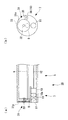
図2(a)は、内視鏡装置における挿入部先端部の断面図である。図2(b)は、挿入部先端部の平面図である。
挿入部先端部7には、図2(a),(b)に示すように、励起光を拡散させる拡散光学部材9と、拡散された励起光を所定波長の蛍光に変換する蛍光部材(蛍光体)16aを有する照明窓16と、被検体から反射された戻り光を受光する固体撮像素子(CCD)10と、戻り光をCCD10の受光面10aに集光して観察画像を結像させる観察光学部材11と、が配置されている。
拡散光学部材9は、挿入部先端部7の略中央に配置され、導光ファイバ6の出射端8から出射される励起光が入射されるように配置されている。拡散光学部材9としては、例えば凹レンズを用いることができるが、凹レンズのような光学レンズに限られることなく励起光を集光するものであればよい。
FIG. 2A is a cross-sectional view of the distal end portion of the insertion portion in the endoscope apparatus. FIG. 2B is a plan view of the distal end portion of the insertion portion.
As shown in FIGS. 2A and 2B, the insertion portion
The diffusing
照明窓16は、励起光により所定波長の蛍光を出射する円板形状に形成された蛍光部材16aから構成されている。照明窓16は、拡散光学部材9の励起光の出射面側に配置されているとともに、照明窓16の中心に配置された軸17により保持されている。軸17は、フレキシブルシャフト(照射位置変更手段)18を介してモータ20と接続されている。モータ20の回転力は、フレキシブルシャフト18および軸17を介して蛍光部材16aに伝達される。フレキシブルシャフト18は、挿入部5内に配置されたコイルパイプ19内を通して配置されている。コイルパイプ19は、回転するフレキシブルシャフト18が挿入部5の内蔵物と直接接触することを防止している。
The
観察光学部材11は、蛍光部材16aが配置されていない領域に配置されているとともに、CCD10の受光面10a側に配置されている。観察光学部材11は、図2(b)に示すように、挿入部5の中心軸線に対して蛍光部材16aから略180°の位相位置に配置されている。
なお、観察光学部材11の配置位置は、被検体からの戻り光が蛍光部材16aに影響されることなく観察光学部材11に入射できる位置であればよく、上述の配置位置に限定されるものではない。
また、観察光学部材11としては、例えば、図2(a)に示すように、一組の光学レンズを用いることができるが、光学レンズに限定されるものではなく、被検体からの戻り光をCCD10の受光面10a上に画像を結像させるものであればよい。
The observation
The arrangement position of the observation
As the observation
CCD10には、受光面10aに結像された画像に基づいて生成された電気信号を伝送するCCDケーブル12が接続されている。CCDケーブル12は挿入部5内に配置され、入力された電気信号を画像処理装置13に伝送するように配置されている。
画像処理装置13に入力された電気信号は、画像処理装置13においてモニタ15に表示できる信号に変換される。画像処理装置13において変換・処理された信号は、信号線14を経由してモニタ15に伝送され、観察画像としてモニタ15に表示される。
Connected to the
The electrical signal input to the
次に、上記の構成からなる内視鏡装置1における作用について説明する。
まず、図1に示すように、制御ユニット21の出力信号に基づき、LD3から蛍光体を励起する励起光(レーザ光)が出射される。出射された励起光は、集光光学部材4に入射して、導光ファイバ6の光入射側の端面に集光され、導光ファイバ6内に入射する。励起光は、図2(a)に示すように、導光ファイバ6により、挿入部5内を挿入部先端部7に配置された拡散光学部材9まで導かれる。拡散光学部材9に入射した励起光は、拡散されて照明窓16に入射する。
照明窓16に入射した励起光は蛍光部材16aにより蛍光に変換され、蛍光は被検体Cに向けて出射される。また、照明窓16に入射した励起光の一部のエネルギは熱に変換され、照明窓16の温度を上昇させる。
Next, the operation of the endoscope apparatus 1 having the above configuration will be described.
First, as shown in FIG. 1, excitation light (laser light) for exciting the phosphor is emitted from the
The excitation light that has entered the
このとき同時に、図1に示すように、制御ユニット21の出力信号に基づき、モータ20が回転駆動され、モータ20の回転はフレキシブルシャフト18に伝えられる。フレキシブルシャフト18に伝えられた回転は、図2(a)に示すように、軸17を介して照明窓16に伝えられる。その結果、照明窓16はモータ20により回転駆動される。
なお、照明窓16の回転方向は一方向に限られることなく、照明窓16が一方向および他方向の双方向に回転されるように構成されていてもよい。
At the same time, as shown in FIG. 1, the
The rotation direction of the
このように、照明窓16が軸17を中心にして回転すると、図2(b)に示すように、拡散光学部材9から射出された励起光が照明される領域を照明窓16が横切るように移動する。つまり、照明窓16の励起光が照射される領域は、照明窓16の同一円周上を移動する。
Thus, when the
観察光学部材11には、図1に示すように、蛍光により照明された被検体Cからの戻り光が入射される。戻り光は、観察光学部材11により、CCD10の受光面10aに結像するように集光される。CCD10は受光面10aに入射した戻り光に応じて電気信号を発生し、電気信号はCCDケーブル12を介して画像処理装置13に伝送される。電気信号は画像処理装置13により処理された信号は信号線14を介してモニタ15に伝送され、モニタ15により被検体Cの観察画像が表示される。
As shown in FIG. 1, return light from the subject C illuminated with fluorescence enters the observation
上記の構成によれば、照明窓16が回転しているため、照明窓16上の励起光が照射されている領域、つまり熱が発生する領域は常に移動している。そのため、発生した熱を分散させることができ、励起光が照射されている領域の温度上昇を抑えることができる。上記領域の温度上昇が抑えられると、蛍光部材16aにおける励起光から蛍光への変換効率低下を抑えることができ、蛍光部材16aから出射される蛍光の光量低下を防止することができる。
According to said structure, since the
また、蛍光部材16aに照射される励起光の強度を増大させても蛍光部材16aの温度上昇を抑制することができるため、蛍光部材16aから出射される蛍光の光量を上げることができる。
さらに、励起光の強度を増大させることができるため、LD3の配置数を増やすことなく蛍光の光量を上げることができる。そのため、内視鏡装置1の小型化・軽量化を図ることができる。
Further, since the temperature rise of the
Furthermore, since the intensity of the excitation light can be increased, the amount of fluorescence can be increased without increasing the number of LD3 arrangements. Therefore, the endoscope apparatus 1 can be reduced in size and weight.
また、蛍光部材16aにおける温度上昇を抑制することができるため、CCD10にける蛍光部材16aの温度上昇に起因するノイズの発生を抑制することができる。
さらに、蛍光部材16aの温度上昇による内視鏡装置1の拡散光学部材9などの構成要素の破損や、各構成要素を接合する接着部の破損などを抑制することができる。
Moreover, since the temperature rise in the
Furthermore, damage to components such as the diffusion
なお、本実施の形態では、照明窓16が軸17に直接固定されているが、ネジなどの固定部材を用いて、軸17に着脱可能に固定してもよい。このように、照明窓16と軸17とを着脱可能とすることにより、照明窓16の破損時における照明窓16の交換が容易となる。
また、照明窓16を交換することにより蛍光部材16aを交換することができる。そのため、所定の波長の蛍光を発する蛍光部材から、他の波長の蛍光を発する蛍光部材への交換を容易に行うことができる。
なお、光源部2と画像処理装置13とモニタ15は、別体であっても一体であってもよい。
In the present embodiment, the
Further, the
The
〔第2の実施の形態〕
次に、本発明の参考例として、第2の実施形態について図3を参照して説明する。
本実施の形態の内視鏡装置の基本構成は、第1の実施の形態と同様であるが、第1の実施の形態とは、挿入部先端部の構成が異なっている。よって、本実施の形態においては、図3を用いて挿入部先端部周辺のみを説明し、画像処理装置等の説明を省略する。
図3(a)は、本実施の形態に係る内視鏡装置の挿入部先端部を説明する断面図であり、図3(b)は、本実施の形態に係る内視鏡装置の挿入部先端部を説明する平面図である。
なお、第1の実施の形態と同一の構成要素には同一の符号を付し、その説明を省略する。
[Second Embodiment]
Next, as a reference example of the present invention, a second embodiment will be described with reference to FIG.
The basic configuration of the endoscope apparatus according to the present embodiment is the same as that of the first embodiment, but the configuration of the distal end portion of the insertion portion is different from that of the first embodiment. Therefore, in the present embodiment, only the vicinity of the distal end portion of the insertion portion will be described using FIG. 3, and the description of the image processing apparatus and the like will be omitted.
FIG. 3A is a cross-sectional view illustrating the distal end portion of the insertion portion of the endoscope apparatus according to the present embodiment, and FIG. 3B is the insertion portion of the endoscope apparatus according to the present embodiment. It is a top view explaining a front-end | tip part.
In addition, the same code | symbol is attached | subjected to the component same as 1st Embodiment, and the description is abbreviate | omitted.
内視鏡装置30の挿入部先端部7には、図3(a),(b)に示すように、励起光を拡散させる拡散光学部材9と、拡散された励起光を所定波長の蛍光に変換する蛍光部材(蛍光体)31aを有する照明窓31と、被検体から反射された戻り光を受光するCCD10と、戻り光をCCD10の受光面10aに集光して観察画像を結像させる観察光学部材11と、が配置されている。
As shown in FIGS. 3A and 3B, the insertion portion
照明窓31は、励起光により所定波長の蛍光を出射する円板形状に形成された蛍光部材31aから構成されている。照明窓31は、拡散光学部材9の励起光の出射面側に配置されているとともに、照明窓31の中心に配置された軸32により回転可能に保持されている。照明窓31の外周面にはギア部(照射位置変更手段)33が形成されており、後述する駆動歯車(照射位置変更手段)35と噛み合うように配置されている。
駆動歯車35は、挿入部先端部7の半径方向外方に配置されているとともに、その中心軸に配置された軸36により保持されている。軸36は挿入部5の半径方向外方に配置されたフレキシブルシャフト18を介してモータ20と接続され(図1参照)、駆動歯車35は、軸36、およびフレキシブルシャフト18を介してモータにより回転されるように配置されている。
The
The
上記の構成からなる内視鏡装置30における作用について説明する。
第1の実施の形態と同様に、制御ユニット21の出力信号に基づきLD3から励起光が出射されると、モータ20によりフレキシブルシャフト18が回転させられる(図1参照)。フレキシブルシャフト18の回転は、図3(b)に示すように、軸36を介して駆動歯車35に伝達される。駆動歯車35の回転はギア部33との噛み合わせにより照明窓31に伝達され、照明窓31は上記モータにより回転駆動される。
なお、照明窓31の回転方向は一方向に限られることなく、照明窓31が一方向および他方向の双方向に回転されるように構成されていてもよい。
The operation of the
Similar to the first embodiment, when excitation light is emitted from the
Note that the rotation direction of the
上記の構成によれば、フレキシブルシャフト18が挿入部5の半径方向外方に配置されているため、挿入部5の半径方向内方の空間を空けることができる。そのため、例えば、上記空間に鉗子などの処置具を挿入部先端部7に導くチャネルを形成することができる。または、上記空間に超音波振動子を配置して、超音波振動による被検体の観察を行うことができる。さらに、上記空間に温度センサを配置することにより、被検体の近傍領域における温度を測定することができる。他には重力方向センサを配置することにより、撮像画像の重力方向を得ることができる。そのため、挿入部先端部7がどの方向に向いているのか、モニタ15に表示されている被検体がどの方向に向いているかという情報を得ることができる。
According to said structure, since the
〔第3の実施の形態〕
次に、本発明の参考例として、第3の実施形態について図4および図5を参照して説明する。
本実施の形態の内視鏡装置の基本構成は、第1の実施の形態と同様であるが、第1の実施の形態とは、挿入部先端部の構成が異なっている。よって、本実施の形態においては、図4および図5を用いて挿入部先端部周辺のみを説明し、画像処理装置等の説明を省略する。
図4は、本実施の形態に係る内視鏡装置の概略を示す模式図である。
なお、第1の実施の形態と同一の構成要素には同一の符号を付し、その説明を省略する。
[Third Embodiment]
Next, a third embodiment will be described with reference to FIGS. 4 and 5 as a reference example of the present invention.
The basic configuration of the endoscope apparatus according to the present embodiment is the same as that of the first embodiment, but the configuration of the distal end portion of the insertion portion is different from that of the first embodiment. Therefore, in the present embodiment, only the vicinity of the distal end portion of the insertion portion will be described with reference to FIGS. 4 and 5, and description of the image processing apparatus and the like will be omitted.
FIG. 4 is a schematic diagram showing an outline of the endoscope apparatus according to the present embodiment.
In addition, the same code | symbol is attached | subjected to the component same as 1st Embodiment, and the description is abbreviate | omitted.
内視鏡装置40は、図4に示すように、励起光を出射する光源部2と、被検体Cの画像を撮像する挿入部5と、撮像された画像信号を処理する画像処理装置13と、処理された観察信号を表示するモニタ15と、から概略構成されている。
光源部2は、所定波長の励起光を出射するLD3と、LD3から出射された励起光を後述する導光ファイバ6に集光する集光光学部材4と、LD3および後述するモータ41を制御する制御ユニット21と、から概略構成されている。
As shown in FIG. 4, the
The
図5(a)は、図4の内視鏡装置における挿入部先端部の断面図である。図5(b)は、図4の内視鏡装置における挿入部先端部の平面図である。
挿入部先端部7には、図5(a),(b)に示すように、励起光を拡散させる拡散光学部材9と、拡散された励起光を所定波長の蛍光に変換する蛍光部材16aを有する照明窓16と、被検体から反射された戻り光を受光するCCD10と、戻り光をCCD10の受光面10aに集光して観察画像を結像させる観察光学部材11と、照明窓16を回転駆動するモータ(照射位置変更手段)41と、が配置されている。
Fig.5 (a) is sectional drawing of the insertion part front-end | tip part in the endoscope apparatus of FIG. FIG. 5B is a plan view of the distal end portion of the insertion portion in the endoscope apparatus of FIG.
As shown in FIGS. 5A and 5B, the insertion portion
照明窓16は、蛍光部材16aから構成され、照明窓16の中心に配置された軸17により保持されている。軸17は、フレキシブルシャフト18を介してモータ41と接続されている。モータ41は、挿入部先端部7内に配置され、信号線42により制御ユニット21と接続されている(図4参照)。
The
上記の構成からなる内視鏡装置40における作用について説明する。
内視鏡装置40は、図4に示すように、制御ユニット21の出力信号に基づきLD3から励起光が出射されると、制御ユニット21の出力信号が信号線42を介してモータ41に伝えられる。
モータ41は、図5(a)に示すように、フレキシブルシャフト18および軸17を介して照明窓41を回転させる。
The operation of the
As shown in FIG. 4, when the excitation light is emitted from the
The
上記の構成によれば、例えば、挿入部5と光源部2とを接続・離脱可能に構成する場合、信号線42および導光ファイバ6の接続のみを確保すればよい。これは、例えば、第1の実施の形態および第2の実施の形態のようなフレキシブルシャフト18の接続を確保する場合と比較して、信号線42および導光ファイバ6の接続は容易であることから、挿入部5と光源部2とを別体で構成することが容易となる。
According to the above configuration, for example, when the
〔第4の実施の形態〕
次に、本発明の参考例として、第4の実施形態について図6および図7を参照して説明する。
本実施の形態の内視鏡装置の基本構成は、第3の実施の形態と同様であるが、第3の実施の形態とは、挿入部先端部の構成が異なっている。よって、本実施の形態においては、図6および図7を用いて挿入部先端部周辺のみを説明し、画像処理装置等の説明を省略する。
図6(a)は、本実施の形態に係る内視鏡装置における挿入部先端部の断面図であり、図6(b)は、本実施の形態に係る内視鏡装置における挿入部先端部の平面図である。
なお、第3の実施の形態と同一の構成要素には同一の符号を付し、その説明を省略する。
[Fourth Embodiment]
Next, a fourth embodiment will be described with reference to FIGS. 6 and 7 as a reference example of the present invention.
The basic configuration of the endoscope apparatus of the present embodiment is the same as that of the third embodiment, but the configuration of the distal end portion of the insertion portion is different from that of the third embodiment. Therefore, in the present embodiment, only the periphery of the distal end portion of the insertion portion will be described using FIG. 6 and FIG.
6A is a cross-sectional view of the distal end portion of the insertion portion in the endoscope apparatus according to the present embodiment, and FIG. 6B is a distal end portion of the insertion portion in the endoscope apparatus according to the present embodiment. FIG.
In addition, the same code | symbol is attached | subjected to the component same as 3rd Embodiment, and the description is abbreviate | omitted.
内視鏡装置50の挿入部先端部7には、図6(a),(b)に示すように、励起光を拡散させる拡散光学部材9と、拡散された励起光を所定波長の蛍光に変換する蛍光部材(蛍光体)51aを有する照明窓51と、被検体から反射された戻り光を受光するCCD10と、戻り光をCCD10の受光面10aに集光して観察画像を結像させる観察光学部材11と、挿入部先端部7の端面を覆うカバーガラス52と、照明窓51を回転駆動する電磁石(照射位置変更手段)53と、が配置されている。
観察光学部材11およびCCD10は、挿入先端部7の略中央部に配置されている。観察光学部材11の周囲には円環状に凹部54が形成されている。
拡散光学部材9は、観察光学部材11の下方(図6(a),(b)中の下方向)に配置されるとともに、凹部54の底面54bに配置されている。
As shown in FIGS. 6A and 6B, the insertion portion
The observation
The diffusing
図7は、本実施の形態に係る内視鏡装置の照明窓を説明する斜視図である。
照明窓51は、図7に示すように、励起光により所定波長の蛍光を出射する円板形状に形成された蛍光部材51aと、蛍光部材51aの外周に配置された外周円筒59と、内周に配置された内周円筒55と、から構成されている。
外周円筒59には、略等間隔に磁性体(照射位置変更手段)56が複数個配置されている。磁性体56はその磁極の向きが一致するように配置されている。例えば、全ての磁性体56のN極が挿入部先端部7の軸線方向後方(図6(a)中の右方向)に向くように配置され、N極が電磁石53と対向するように配置されている。
なお、磁性体56は、図7に示すように、複数配置されていてもよいし、1つだけ配置されていてもよい。
FIG. 7 is a perspective view for explaining an illumination window of the endoscope apparatus according to the present embodiment.
As shown in FIG. 7, the
A plurality of magnetic bodies (irradiation position changing means) 56 are arranged on the outer
A plurality of
凹部54の内周側面54aは、図6(a),(b)に示すように、内周円筒55内に挿入され、照明窓51を回転可能に保持している。凹部54の底面54bは、外周円筒59および内周円筒55の一方の端面と当接することにより、照明窓51の挿入部先端部7の軸線方向後方への動きを規制している。
カバーガラス52は、蛍光および被検体からの戻り光を透過する透明材料から形成されている。また、カバーガラス52は、挿入部先端部7の端部に配置され、照明窓51の挿入部先端部7の軸線方向前方(図6(a)中の左方向)への動きを規制している。
As shown in FIGS. 6A and 6B, the inner
The
電磁石53は、磁性体56に対向する位置に配置されるとともに、同一円周上に等間隔に配置されている。磁性体53はコイルからなり、磁性体53は、コイルの軸線と挿入部先端部7の軸線とが略平行になるように配置されている。また、電磁石53は、配線57,58を介して制御ユニット21(図4参照)に接続されている。電磁石53に供給する電流の向きを制御することにより、電磁石53に発生する磁極の向きを制御することができる。
The
上記の構成からなる内視鏡装置50における作用について説明する。
まず、第1の実施の形態と同様に、制御ユニット21の出力信号に基づきLD3から励起光が出射され、励起光が照明窓51に照射される。
これと同時に、制御ユニット21は、電磁石53に供給する電流の向きを制御することで照明窓51を回転させる。
The operation of the
First, as in the first embodiment, excitation light is emitted from the
At the same time, the
具体的には、まず、磁性体56に対向する電磁石53に、電磁石53の磁性体56側の端部がS極となる電流を供給する。他の電磁石53には、磁性体56側の端部がN極となる電流を供給する。すると、磁性体56のN極と電磁石53のS極とが引き合う。
Specifically, first, a current is supplied to the
次に、電磁石53の照明窓51を回転させる方向に隣接した他の電磁石53に、電磁石53の磁性体56側の端部がS極となる電流を供給する。それと同時に電磁石53には、電磁石53の磁性体56側の端部がN極となる電流を供給する。すると、上記電磁石53に隣接した他の電磁石53と磁性体56とが引き合い、照明窓51が回転する。
上述の制御を繰り返すことにより、照明窓51は、電磁石53により回転駆動される。
Next, a current is supplied to the
By repeating the above control, the
上記の構成によれば、照明窓51の面積を、第1の実施の形態から第3の実施の形態までと比較して、さらに広く設けることができるため、蛍光部材51aの面積もさらに広く設けることができる。そのため、蛍光部材51aの励起光の照射領域で発生する熱をより広い面積に分散させることができ、蛍光部材51aの温度上昇をより効果的に抑制することができる。その結果、蛍光部材51aにおける励起光から蛍光への変換効率低下を効果的に抑えることができ、蛍光部材51aから出射される蛍光の光量低下を効果的に防止することができる。
また、蛍光部材51aに照射される励起光の強度を更に上げても蛍光部材51aの温度上昇を抑制することができるため、蛍光部材51aから出射される蛍光の光量を更に上げることができる。
According to said structure, since the area of the
Further, since the temperature rise of the
また、例えば、挿入部5と光源部2とを接続・離脱可能に構成する場合、配線57,58および導光ファイバ6の接続のみを確保すればよい。これは、例えば、第1の実施の形態および第2の実施の形態のようなフレキシブルシャフト18の接続を確保する場合と比較して、配線57,58および導光ファイバ6の接続は容易であることから、挿入部5と光源部2とを別体で構成することが容易となる。
Further, for example, when the
〔第5の実施の形態〕
次に、本発明の第5の実施形態について図8および図9を参照して説明する。
本実施の形態の内視鏡装置の基本構成は、第3の実施の形態と同様であるが、第3の実施の形態とは、挿入部先端部の構成が異なっている。よって、本実施の形態においては、図8および図9を用いて挿入部先端部周辺のみを説明し、画像処理装置等の説明を省略する。
図8(a)は、本実施の形態に係る内視鏡装置における挿入部先端部の断面図であり、図8(b)は、本実施の形態に係る内視鏡装置における挿入部先端部の平面図である。
[Fifth Embodiment]
Next, a fifth embodiment of the present invention will be described with reference to FIGS.
The basic configuration of the endoscope apparatus of the present embodiment is the same as that of the third embodiment, but the configuration of the distal end portion of the insertion portion is different from that of the third embodiment. Therefore, in this embodiment, only the periphery of the distal end portion of the insertion portion will be described with reference to FIGS.
FIG. 8A is a cross-sectional view of the distal end portion of the insertion portion in the endoscope apparatus according to the present embodiment, and FIG. 8B is a distal end portion of the insertion portion in the endoscope apparatus according to the present embodiment. FIG.
内視鏡装置60の挿入部先端部7には、図8(a),(b)に示すように、励起光を拡散させる拡散光学部材9と、拡散された励起光を所定波長の蛍光に変換する蛍光部材(蛍光体)61aを有する照明窓61と、被検体から反射された戻り光を受光するCCD10と、戻り光をCCD10の受光面に集光して観察画像を結像させる観察光学部材11と、照明窓61を回動駆動する電磁石(照射位置変更手段)62R,62Lと、が配置されている。
観察光学部材11およびCCD10は、挿入先端部7の下方(図8(b)中の下側)に配置されている。拡散光学部材9は、挿入先端部7の上方(図8(b)中の上側)に配置されている。
As shown in FIGS. 8A and 8B, the insertion portion
The observation
照明窓61は、励起光により所定波長の蛍光を射出する扇形に形成された板からなる蛍光部材61aと、蛍光部材61aの二辺に配置された磁性体(照射位置変更手段)63と、から構成されている。
照明窓61は、その頂点が挿入部先端部7の略中央に位置するように配置されているとともに、蛍光部材61aにより拡散光学部材9の前面を覆うように配置されている。また、照明窓61は、その頂点近傍領域において軸17に回転可能に保持されている。
磁性体63は、N極が下方(図8(b)の下側)に、S極が上方(図8(b)の上側)になるように配置されている。
The
The
The
電磁石62R,62Lは、コイルからなり、磁性体62R,62Lは、コイルの軸線と挿入部先端部7の軸線とが略平行になるように配置されている。電磁石62R,62Lの端部には、円筒形の金属からなるストッパ(照射位置変更手段)64R、64Lが配置されている。ストッパ64R、64Lの一方の端部はそれぞれ電磁石62R,62Lと接触するように配置され、他方の端部は挿入部先端部7の先端面から突出して配置されている。また、電磁石62R,62Lは、配線64,65を介して制御ユニット21(図4参照)に接続されている。電磁石62R,62Lに供給する電流の向きを制御することにより、ストッパ64R、64Lの端部に発生する磁極を制御することができる。
ストッパ64Rおよび電磁石62Rは、図8(b)に示すように、観察光学部材11の右斜め上に配置され、ストッパ64Lおよび電磁石62Lは、観察光学部材11の左斜め上に配置されている。
The
As shown in FIG. 8B, the stopper 64 </ b> R and the electromagnet 62 </ b> R are arranged diagonally on the right side of the observation
上記の構成からなる内視鏡装置60における作用について説明する。
まず、第1の実施の形態と同様に、制御ユニット21の出力信号に基づきLD3から励起光が出射され、励起光が照明窓51に照射される。
これと同時に、制御ユニット21は、電磁石62R,62Lに供給する電流の向きを制御することで照明窓51を回動制御する。
The operation of the
First, as in the first embodiment, excitation light is emitted from the
At the same time, the
図9(a)は、内視鏡装置の照明窓が一方に回動したときの挿入部先端部の平面図であり、図9(b)は、内視鏡装置の照明窓が他方に回動したときの挿入部先端部の平面図である。
具体的には、まず、制御ユニット21は、ストッパ64Rの端部にS極が形成される電流を電磁石62Rに供給する。それと同時にストッパ64Lの端部にN極が形成される電流を電磁石62Lに供給する。すると、磁性体63のN極とストッパ64RのS極とが引き合うとともに、ストッパ64LのN極とは反発して、図9(a)に示すように、照明窓61は右方向に回動する。照明窓61は、ストッパ64Rと当接して回動が止まる。
FIG. 9A is a plan view of the distal end portion of the insertion portion when the illumination window of the endoscope apparatus is rotated to one side, and FIG. 9B is a plan view of the illumination window of the endoscope apparatus that is rotated to the other side. It is a top view of an insertion part tip part when it moves.
Specifically, first, the
次に、ストッパ64Lの端部にS極が形成される電流を電磁石62Lに供給し、ストッパ64Rの端部にN極が形成される電流を電磁石62Rに供給する。すると、磁性体63のN極とストッパ64LのS極とが引き合うとともに、ストッパ64RのN極とは反発して、図9(b)に示すように、照明窓61は左方向に回動する。照明窓61は、ストッパ64Lと当接して回動が止まる。
上述の制御を繰り返すことにより、照明窓61は左右交互に回動駆動される。
Next, a current for forming the south pole at the end of the
By repeating the above-described control, the
上記の構成によれば、例えば、挿入部5と光源部2とを接続・離脱可能に構成する場合、配線64,65および導光ファイバ6の接続のみを確保すればよい。これは、例えば、第1の実施の形態および第2の実施の形態のようなフレキシブルシャフト18の接続を確保する場合と比較して、配線64,65および導光ファイバ6の接続は容易であることから、挿入部5と光源部2とを別体で構成することが容易となる。
According to the above configuration, for example, when the
〔第6の実施の形態〕
次に、本発明の参考例として、第6の実施形態について図10を参照して説明する。
本実施の形態の内視鏡装置の基本構成は、第1の実施の形態と同様であるが、第1の実施の形態とは、挿入部先端部の構成が異なっている。よって、本実施の形態においては、図10を用いて挿入部先端部周辺のみを説明し、画像処理装置等の説明を省略する。
図10(a)は、本実施の形態に係る内視鏡装置における挿入部先端部の断面図であり、図10(b)は、本実施の形態に係る内視鏡装置における挿入部先端部の平面図である。
なお、第1の実施の形態と同一の構成要素には同一の符号を付し、その説明を省略する。
[Sixth Embodiment]
Next, as a reference example of the present invention, a sixth embodiment will be described with reference to FIG.
The basic configuration of the endoscope apparatus according to the present embodiment is the same as that of the first embodiment, but the configuration of the distal end portion of the insertion portion is different from that of the first embodiment. Therefore, in the present embodiment, only the vicinity of the distal end portion of the insertion portion will be described using FIG. 10, and the description of the image processing apparatus and the like will be omitted.
FIG. 10A is a cross-sectional view of the distal end portion of the insertion portion in the endoscope apparatus according to the present embodiment, and FIG. 10B is a distal end portion of the insertion portion in the endoscope apparatus according to the present embodiment. FIG.
In addition, the same code | symbol is attached | subjected to the component same as 1st Embodiment, and the description is abbreviate | omitted.
内視鏡装置70の挿入部先端部7には、図10(a),(b)に示すように、励起光を拡散させる拡散光学部材9と、拡散された励起光を所定波長の蛍光に変換する蛍光部材(蛍光体)71aを有する照明窓71と、被検体から反射された戻り光を受光するCCD10と、戻り光をCCD10の受光面10aに集光して観察画像を結像させる観察光学部材11と、が配置されている。
As shown in FIGS. 10A and 10B, the insertion portion
照明窓71は、励起光により所定波長の蛍光を出射する円板形状に形成された蛍光部材71aから構成されている。照明窓71は、拡散光学部材9の励起光の出射面側に配置されているとともに、照明窓71の中心に配置された軸17により回転可能に保持されている。照明窓31の外周面には円筒状のフィン72が配置されており、フィン72の内周面には、凹部73が等間隔に形成されている。
The
上記の構成からなる内視鏡装置70における作用について説明する。
第1の実施の形態と同様に、制御ユニット21の出力信号に基づきLD3から励起光が出射されると、モータ20によりフレキシブルシャフト18が回転させられる(図1参照)。フレキシブルシャフト18の回転は、図10(b)に示すように、軸17を介して照明窓71に伝達される。
The operation of the
Similar to the first embodiment, when excitation light is emitted from the
上記の構成によれば、照明窓71が回転駆動されるとフィン72も回転駆動される。フィン72が回転駆動されると凹部73により風が発生し、挿入部先端部7周り、特に蛍光部材71aを冷却することができる。よって、さらに蛍光部材16aに照射する励起光の強度を増大させることができ、蛍光部材16aから出射される蛍光の光量を上げることができる。
According to said structure, if the
〔第7の実施の形態〕
次に、本発明の参考例として、第7の実施形態について図11を参照して説明する。
本実施の形態の内視鏡装置の基本構成は、第1の実施の形態と同様であるが、第1の実施の形態とは、挿入部先端部の構成が異なっている。よって、本実施の形態においては、図11を用いて挿入部先端部周辺のみを説明し、画像処理装置等の説明を省略する。
図11(a)は、本実施の形態に係る内視鏡装置における挿入部先端部の断面図であり、図11(b)は、本実施の形態に係る内視鏡装置における挿入部先端部の平面図である。
なお、第1の実施の形態と同一の構成要素には同一の符号を付し、その説明を省略する。
[Seventh Embodiment]
Next, as a reference example of the present invention, a seventh embodiment will be described with reference to FIG.
The basic configuration of the endoscope apparatus according to the present embodiment is the same as that of the first embodiment, but the configuration of the distal end portion of the insertion portion is different from that of the first embodiment. Therefore, in the present embodiment, only the vicinity of the distal end portion of the insertion portion will be described using FIG. 11, and the description of the image processing apparatus and the like will be omitted.
FIG. 11A is a cross-sectional view of the distal end portion of the insertion portion in the endoscope apparatus according to the present embodiment, and FIG. 11B is a distal end portion of the insertion portion in the endoscope apparatus according to the present embodiment. FIG.
In addition, the same code | symbol is attached | subjected to the component same as 1st Embodiment, and the description is abbreviate | omitted.
内視鏡装置80の挿入部先端部7には、図11(a),(b)に示すように、励起光を拡散させる拡散光学部材9と、拡散された励起光を所定波長の蛍光に変換する蛍光部材(蛍光体)81a、81bを有する照明窓81と、被検体から反射された戻り光を受光するCCD10と、戻り光をCCD10の受光面10aに集光して観察画像を結像させる観察光学部材11と、が配置されている。
As shown in FIGS. 11A and 11B, the insertion portion
照明窓81には、励起光により白色光蛍光を出射する蛍光部材81aと励起光により紫外光蛍光を出射する蛍光部材81bとが備えられている。照明窓81は、拡散光学部材9の励起光の出射面側に配置されているとともに、照明窓81の中心に配置された軸17により回転可能に保持されている
なお、上述のように、蛍光部材81a,81bから出射される蛍光が白色光と紫外光であってもよいし、観察する対象・観察する目的に合わせて他の波長の光の組み合わせとしてもよい。
The
上記の構成からなる内視鏡装置80における作用について説明する。
第1の実施の形態と同様に、制御ユニット21の出力信号に基づきLD3から励起光が出射されると、モータ20によりフレキシブルシャフト18が回転させられる(図1参照)。フレキシブルシャフト18の回転は、図10(b)に示すように、軸17を介して照明窓81に伝達される。
照明窓81の蛍光部材81aに励起光が入射すると、蛍光部材81aから白色光が出射される。照明窓81が回転して励起光が蛍光部材81bに入射すると、蛍光部材81bから紫外光が出射される。
The operation of the
Similar to the first embodiment, when excitation light is emitted from the
When excitation light enters the
上記の構成によれば、1本の内視鏡装置80から白色光と紫外光とを交番照射することができる。そのため、2種類の照射光を用いた観察を1本の内視鏡装置80を用いて行うことができる。
なお、上述のように、1つの照明窓81に2種類の蛍光部材81a,81bを配置してもよいし3種類以上の蛍光部材を配置してもよい。この構成によれば、1本の内視鏡装置でより多くの波長の照明光を用いた観察を行うことができる。
According to the above configuration, white light and ultraviolet light can be alternately irradiated from one
As described above, two types of
〔第8の実施の形態〕
次に、本発明の参考例として、第8の実施形態について図12を参照して説明する。
本実施の形態の内視鏡装置の基本構成は、第4の実施の形態と同様であるが、第4の実施の形態とは、挿入部先端部の構成が異なっている。よって、本実施の形態においては、図12を用いて挿入部先端部周辺のみを説明し、画像処理装置等の説明を省略する。
図12は、本実施の形態に係る内視鏡装置における挿入部先端部の断面図である。
なお、第4の実施の形態と同一の構成要素には同一の符号を付し、その説明を省略する。
[Eighth Embodiment]
Next, as a reference example of the present invention, an eighth embodiment will be described with reference to FIG.
The basic configuration of the endoscope apparatus of the present embodiment is the same as that of the fourth embodiment, but the configuration of the distal end portion of the insertion portion is different from that of the fourth embodiment. Therefore, in the present embodiment, only the vicinity of the distal end portion of the insertion portion will be described using FIG. 12, and the description of the image processing apparatus and the like will be omitted.
FIG. 12 is a cross-sectional view of the distal end portion of the insertion portion in the endoscope apparatus according to the present embodiment.
In addition, the same code | symbol is attached | subjected to the component same as 4th Embodiment, and the description is abbreviate | omitted.
内視鏡装置90の挿入部先端部7には、図12に示すように、光学アダプタ91が着脱可能に配置されている。
挿入部先端部7には、励起光を拡散させる拡散光学部材9と、被検体から反射された戻り光を受光するCCD10と、戻り光をCCD10の受光面10aに集光して観察画像を結像させる観察光学部材11と、照明窓51を回転駆動する電磁石53と、が配置されている。また、挿入部先端部7の外周面には光学アダプタ91と螺合するネジ部7aが形成されている。
As shown in FIG. 12, an optical adapter 91 is detachably disposed at the
At the
光学アダプタ91は、外周面を形成する円筒部92と、励起光から蛍光を出射する照明窓51と、戻り光を観察光学部材11に入射させるアダプタ光学部材93と、アダプタ光学部材93を保持する前方カバーガラス94と、前方カバーガラス94とともに照明窓51を回転可能に支持する後方カバーガラス95と、から概略構成されている。
円筒部92の一方の端部内面には、挿入部先端部7のネジ部7aと螺合する円筒部ネジ部92aが形成されている。他方の端部には前方カバーガラス94と後方カバーガラス95とが配置されている。
The optical adapter 91 holds a cylindrical portion 92 that forms an outer peripheral surface, an
A cylindrical portion screw portion 92 a that is screwed with the screw portion 7 a of the insertion portion
前方カバーガラス94は、CCD10と対向する位置に円筒94aが形成された透明円板から構成されている。円筒94aの内部にはアダプタ光学部材93が配置されている。円筒94aの外周には照明窓51が回転可能に配置されている。後方カバーガラス95は透明円板から構成されており、前方カバーガラス94の円筒94aと接触するように配置されている。このように配置することにより、照明窓51が光学アダプタ91から脱落することを防止している。
The front cover glass 94 is composed of a transparent disk having a cylinder 94 a formed at a position facing the
上記の構成からなる内視鏡装置90における作用について説明する。
まず、第1の実施の形態と同様に、制御ユニット21の出力信号に基づきLD3から励起光が出射され、励起光が照明窓51に照射される。これと同時に、制御ユニット21は、電磁石53に供給する電流の向きを制御することで照明窓51が回転される。
照明窓51からは所定波長の蛍光が出射され被検体を照明する。被検体からの戻り光はアダプタ光学部材93に入射して、観察光学部材11を介してCCD10に像を結像する。
The operation of the endoscope apparatus 90 having the above configuration will be described.
First, as in the first embodiment, excitation light is emitted from the
From the
上記の構成によれば、光学アダプタ91を交換することにより、光学アダプタ91内の照明窓51も同時に交換することができる。そのため、照明窓51を容易に交換することができ、照明する蛍光の波長を容易に変更することができる。
また、アダプタ光学部材93も容易に交換することができるため、1本の内視鏡装置90により複数の視野角による観察を容易に行うことができる。
According to said structure, the
In addition, since the adapter optical member 93 can also be easily replaced, observation with a plurality of viewing angles can be easily performed by the single endoscope device 90.
なお、本発明の技術範囲は上記実施形態に限定されるものではなく、本発明の趣旨を逸脱しない範囲において種々の変更を加えることが可能である。
例えば、上記の実施の形態においては、励起光の光源としてレーザダイオード(LD)を用いるものに適用して説明したが、励起光の光源はレーザダイオードに限られることなく、発光ダイオード(LED)等、その他各種の光源を用いたものに適用することができるものである。
The technical scope of the present invention is not limited to the above embodiment, and various modifications can be made without departing from the spirit of the present invention.
For example, in the above-described embodiment, the description is applied to the case where a laser diode (LD) is used as a light source of excitation light. However, the light source of excitation light is not limited to a laser diode, and a light emitting diode (LED) or the like. The present invention can be applied to other types using various light sources.
1、30、40、50、60、70、80、90 内視鏡装置
2 光源部(光源)
3 LD(レーザダイオード)
5 挿入部
16、31、51、61、71、81 照明窓
16a、31a、51a、61a、71a、81a、81b 蛍光部材(蛍光体)
18 フレキシブルシャフト(照射位置変更手段)
20、41 モータ(照射位置変更手段)
33 ギア部(照射位置変更手段)
35 駆動歯車(照射位置変更手段)
53、62R、62L 電磁石(照射位置変更手段)
56、63 磁性体(照射位置変更手段)
64R、64L ストッパ(照射位置変更手段)
1, 30, 40, 50, 60, 70, 80, 90
3 LD (Laser Diode)
5
18 Flexible shaft (irradiation position changing means)
20, 41 Motor (irradiation position changing means)
33 Gear part (irradiation position changing means)
35 Drive gear (irradiation position changing means)
53, 62R, 62L Electromagnet (irradiation position changing means)
56, 63 Magnetic body (irradiation position changing means)
64R, 64L stopper (irradiation position changing means)
Claims (4)
被検査対象空間内に挿入される可撓性を有する挿入部と、
該挿入部の先端に配置され、前記光源から発せられた励起光を拡散させる拡散光学部材と、
前記挿入部の先端面に配置された観察光学系と、
該拡散光学部材の励起光の出射面側に配置され、前記励起光により励起されて一種類の蛍光を発する扇形に形成された板から構成されている蛍光体と、前記蛍光体の側面に配置された磁性体とから構成される照明窓と、
前記挿入部の前記観察光学系を備えた面の略中央且つ前記扇形の要の位置に設けられた軸線回りに、前記挿入部の先端面に配置された電磁石により前記照明窓を回動させ、前記照明窓における前記励起光の照射位置を変化させる照射位置変更手段とを備える内視鏡装置。 A light source that emits excitation light;
A flexible insertion section to be inserted into the space to be inspected;
A diffusing optical member that is disposed at the tip of the insertion portion and diffuses the excitation light emitted from the light source;
An observation optical system disposed on the distal end surface of the insertion portion;
A phosphor arranged on the exit surface side of the excitation light of the diffusing optical member, and composed of a fan-shaped plate excited by the excitation light and emitting one kind of fluorescence, and disposed on the side of the phosphor An illumination window composed of a magnetic material made of
The illumination window is rotated by an electromagnet disposed on the distal end surface of the insertion portion around an axis provided at a substantially central position of the surface of the insertion portion including the observation optical system and at a position of the fan shape , An endoscope apparatus comprising irradiation position changing means for changing an irradiation position of the excitation light in the illumination window.
前記照明窓が、この光学アダプタに設けられている請求項1から3のいずれかに記載の内視鏡装置。 It further comprises an optical adapter that can be attached to and detached from the distal end of the insertion portion,
The endoscope apparatus according to claim 1, wherein the illumination window is provided in the optical adapter.
Priority Applications (1)
| Application Number | Priority Date | Filing Date | Title |
|---|---|---|---|
| JP2004209849A JP4782992B2 (en) | 2004-07-16 | 2004-07-16 | Endoscope device |
Applications Claiming Priority (1)
| Application Number | Priority Date | Filing Date | Title |
|---|---|---|---|
| JP2004209849A JP4782992B2 (en) | 2004-07-16 | 2004-07-16 | Endoscope device |
Publications (3)
| Publication Number | Publication Date |
|---|---|
| JP2006026135A JP2006026135A (en) | 2006-02-02 |
| JP2006026135A5 JP2006026135A5 (en) | 2007-08-16 |
| JP4782992B2 true JP4782992B2 (en) | 2011-09-28 |
Family
ID=35893148
Family Applications (1)
| Application Number | Title | Priority Date | Filing Date |
|---|---|---|---|
| JP2004209849A Expired - Fee Related JP4782992B2 (en) | 2004-07-16 | 2004-07-16 | Endoscope device |
Country Status (1)
| Country | Link |
|---|---|
| JP (1) | JP4782992B2 (en) |
Families Citing this family (15)
| Publication number | Priority date | Publication date | Assignee | Title |
|---|---|---|---|---|
| JP5185520B2 (en) * | 2006-09-22 | 2013-04-17 | オリンパス株式会社 | Electronic endoscope device |
| JP5384041B2 (en) * | 2008-06-19 | 2014-01-08 | 富士フイルム株式会社 | Endoscope |
| JP5150388B2 (en) * | 2008-07-01 | 2013-02-20 | 富士フイルム株式会社 | Endoscope |
| JP2010081957A (en) * | 2008-09-29 | 2010-04-15 | Olympus Corp | Light source device |
| WO2010064322A1 (en) | 2008-12-05 | 2010-06-10 | オリンパス株式会社 | Illuminating apparatus and endoscope apparatus |
| DE102009040095B4 (en) * | 2009-09-04 | 2013-07-04 | Olympus Winter & Ibe Gmbh | Medical lamp with fluorescent coating |
| JP5397684B2 (en) * | 2009-09-30 | 2014-01-22 | カシオ計算機株式会社 | Light source device and projector |
| JP2012098442A (en) * | 2010-11-01 | 2012-05-24 | Seiko Epson Corp | Wavelength conversion element, light source device, and projector |
| JP2012098438A (en) * | 2010-11-01 | 2012-05-24 | Seiko Epson Corp | Wavelength conversion element, light source device, and projector |
| JP2013048792A (en) * | 2011-08-31 | 2013-03-14 | Fujifilm Corp | Endoscopic device |
| EP2777482B1 (en) * | 2011-11-10 | 2016-09-14 | Fujifilm Corporation | Illumination optics unit for endoscope and method for producing same |
| JP5927011B2 (en) * | 2012-04-10 | 2016-05-25 | オリンパス株式会社 | Endoscope device |
| JP6103820B2 (en) * | 2012-05-11 | 2017-03-29 | オリンパス株式会社 | Endoscope illumination optical system and endoscope |
| JP5675911B2 (en) * | 2013-08-07 | 2015-02-25 | オリンパス株式会社 | Fiber optic lighting equipment |
| JP5997676B2 (en) * | 2013-10-03 | 2016-09-28 | 富士フイルム株式会社 | Endoscope light source device and endoscope system using the same |
Family Cites Families (8)
| Publication number | Priority date | Publication date | Assignee | Title |
|---|---|---|---|---|
| JPS63234941A (en) * | 1986-11-29 | 1988-09-30 | オリンパス光学工業株式会社 | Image pickup apparatus |
| JPS6474522A (en) * | 1987-09-16 | 1989-03-20 | Olympus Optical Co | Endoscope |
| JP2703679B2 (en) * | 1991-09-13 | 1998-01-26 | オリンパス光学工業株式会社 | Optical axis adjustment device of light source device |
| JPH09153645A (en) * | 1995-11-30 | 1997-06-10 | Toyoda Gosei Co Ltd | Group-iii nitride semiconductor light-emitting device |
| JPH11104060A (en) * | 1997-10-03 | 1999-04-20 | Olympus Optical Co Ltd | Fluorescent observation device |
| JP3278393B2 (en) * | 1998-02-03 | 2002-04-30 | オリンパス光学工業株式会社 | Endoscope device |
| JP5157029B2 (en) * | 2001-05-31 | 2013-03-06 | 日亜化学工業株式会社 | Light emitting device using phosphor |
| US6921920B2 (en) * | 2001-08-31 | 2005-07-26 | Smith & Nephew, Inc. | Solid-state light source |
-
2004
- 2004-07-16 JP JP2004209849A patent/JP4782992B2/en not_active Expired - Fee Related
Also Published As
| Publication number | Publication date |
|---|---|
| JP2006026135A (en) | 2006-02-02 |
Similar Documents
| Publication | Publication Date | Title |
|---|---|---|
| JP4782992B2 (en) | Endoscope device | |
| JP4837321B2 (en) | Endoscope device | |
| JP4812430B2 (en) | Endoscope device | |
| JP4689190B2 (en) | Endoscope device and endoscope adapter | |
| JP4370199B2 (en) | Endoscope device and endoscope adapter | |
| JP4782571B2 (en) | Illumination system for viewing devices with variable viewing direction | |
| US20110257484A1 (en) | Light source device and endoscope apparatus using the same | |
| US20110257483A1 (en) | Light source device and endoscope apparatus using the same | |
| JP2006296656A (en) | Endoscope apparatus | |
| JP2006521574A (en) | Arrangements for illuminating objects with light of different wavelengths | |
| JP6300890B2 (en) | Endoscope light source device | |
| JP2007021084A (en) | Endoscope | |
| JP2007044350A (en) | Endoscope | |
| JP4713922B2 (en) | Endoscope device | |
| JP2009072213A (en) | Endoscope light source unit and endoscope system | |
| JP6009792B2 (en) | Light source device | |
| JP5927086B2 (en) | Light source device | |
| JP2011050667A (en) | Optical scan type endoscope | |
| JP2005152131A (en) | Endoscope apparatus | |
| JP4709576B2 (en) | Endoscope device | |
| JP4540390B2 (en) | Endoscope device | |
| JP2002095624A (en) | Fluorescence endoscope system | |
| JP5145119B2 (en) | Endoscope light source device | |
| JP6359998B2 (en) | Endoscope | |
| JP2006158789A (en) | Endoscope |
Legal Events
| Date | Code | Title | Description |
|---|---|---|---|
| A521 | Written amendment |
Free format text: JAPANESE INTERMEDIATE CODE: A523 Effective date: 20070627 |
|
| A621 | Written request for application examination |
Free format text: JAPANESE INTERMEDIATE CODE: A621 Effective date: 20070627 |
|
| A977 | Report on retrieval |
Free format text: JAPANESE INTERMEDIATE CODE: A971007 Effective date: 20100224 |
|
| A131 | Notification of reasons for refusal |
Free format text: JAPANESE INTERMEDIATE CODE: A131 Effective date: 20100302 |
|
| A521 | Written amendment |
Free format text: JAPANESE INTERMEDIATE CODE: A523 Effective date: 20100506 |
|
| A131 | Notification of reasons for refusal |
Free format text: JAPANESE INTERMEDIATE CODE: A131 Effective date: 20100622 |
|
| A521 | Written amendment |
Free format text: JAPANESE INTERMEDIATE CODE: A523 Effective date: 20100820 |
|
| A131 | Notification of reasons for refusal |
Free format text: JAPANESE INTERMEDIATE CODE: A131 Effective date: 20101019 |
|
| A521 | Written amendment |
Free format text: JAPANESE INTERMEDIATE CODE: A523 Effective date: 20101220 |
|
| A131 | Notification of reasons for refusal |
Free format text: JAPANESE INTERMEDIATE CODE: A131 Effective date: 20110301 |
|
| A521 | Written amendment |
Free format text: JAPANESE INTERMEDIATE CODE: A523 Effective date: 20110502 |
|
| TRDD | Decision of grant or rejection written | ||
| A01 | Written decision to grant a patent or to grant a registration (utility model) |
Free format text: JAPANESE INTERMEDIATE CODE: A01 Effective date: 20110621 |
|
| A01 | Written decision to grant a patent or to grant a registration (utility model) |
Free format text: JAPANESE INTERMEDIATE CODE: A01 |
|
| A61 | First payment of annual fees (during grant procedure) |
Free format text: JAPANESE INTERMEDIATE CODE: A61 Effective date: 20110708 |
|
| FPAY | Renewal fee payment (event date is renewal date of database) |
Free format text: PAYMENT UNTIL: 20140715 Year of fee payment: 3 |
|
| R151 | Written notification of patent or utility model registration |
Ref document number: 4782992 Country of ref document: JP Free format text: JAPANESE INTERMEDIATE CODE: R151 |
|
| FPAY | Renewal fee payment (event date is renewal date of database) |
Free format text: PAYMENT UNTIL: 20140715 Year of fee payment: 3 |
|
| S531 | Written request for registration of change of domicile |
Free format text: JAPANESE INTERMEDIATE CODE: R313531 |
|
| R350 | Written notification of registration of transfer |
Free format text: JAPANESE INTERMEDIATE CODE: R350 |
|
| R250 | Receipt of annual fees |
Free format text: JAPANESE INTERMEDIATE CODE: R250 |
|
| LAPS | Cancellation because of no payment of annual fees |