JP4782277B2 - Infrared color image forming device - Google Patents
Infrared color image forming device Download PDFInfo
- Publication number
- JP4782277B2 JP4782277B2 JP2000363648A JP2000363648A JP4782277B2 JP 4782277 B2 JP4782277 B2 JP 4782277B2 JP 2000363648 A JP2000363648 A JP 2000363648A JP 2000363648 A JP2000363648 A JP 2000363648A JP 4782277 B2 JP4782277 B2 JP 4782277B2
- Authority
- JP
- Japan
- Prior art keywords
- infrared
- color
- image
- spectrum
- reflectance
- Prior art date
- Legal status (The legal status is an assumption and is not a legal conclusion. Google has not performed a legal analysis and makes no representation as to the accuracy of the status listed.)
- Expired - Fee Related
Links
Images


Description
【0001】
【発明の属する技術分野】
本発明は、対象物についての画像を赤外線カメラで取得するとともに、その対象物の赤外線放射強度又は赤外線反射率の値を検出し、この値からその対象物のカラー情報を得てカラー画像を形成する赤外線カラー画像形成装置に関する。
【0002】
【従来の技術】
従来の赤外線カメラでは赤外線強度を有する画像しか得られなかった。赤外線カメラで着色画像が得られるものとしては、人体温度や地球画像を、温度範囲を色情報として着色した画像がある。この種のカラー表示映像装置は、被測定物体上の各点を水平、垂直走査して、被測定物体から放射される赤外線を赤外線検出装置により電気的に検出し、この信号強度に応じた複数階調に色付けし、ブラウン管等の表示装置に擬似カラー映像として映出し、映出された画像を定量、定性的に測定して分析等に供する構成である。
【0003】
【発明が解決しようとする課題】
このように、従来は、赤外線カメラでは、赤外線強度画像しか得られない。そして、赤外線カメラで着色画像を作っても、疑似カラーであるため、対象物の実際に近いカラー画像は期待できないという問題があった。
【0004】
本発明は、このような従来の問題点を解決することを目的とするものであり、その具体的な課題は、対象物について赤外線カメラで得た画像に、適当なカラー情報を加えることによって、対象物の実際に近いカラー画像を得ることが可能な赤外線カラー画像形成装置を実現することである。
【0005】
【課題を解決するための手段】
本発明は上記課題を解決するために、対象物から放射又は反射される赤外線を受光し、赤外スペクトル画像を得る赤外線カメラと、該対象物について、色と、赤外スペクトル放射強度又は赤外スペクトル反射率との対応データを予め記憶する記憶装置と、該対応データに基づいて、前記赤外スペクトル画像の各位置における赤外スペクトルの放射強度又は赤外スペクトル反射率の値から、前記赤外スペクトル画像の各位置における色を決定する第1の処理手段と、前記第1の処理手段で得た色情報を基に、前記対象物の画像の各位置に人工的に着色を施す第2の処理手段と、を備えていることを特徴とする赤外線カラー画像形成装置を提供する。
【0006】
さらに、本発明は上記課題を解決するために、対象物に波長の異なる赤外線を照射する赤外線照射手段と、前記対象物からの反射光をそれぞれ別個に受光し画像を得る複数の赤外線カメラと、該対象物について、色と赤外スペクトル放射強度又は赤外スペクトル反射率との対応データを予め記憶する記憶装置と、前記各赤外線カメラ毎で取得した各波長毎の赤外スペクトル放射強度又は赤外スペクトル反射率の値から、前記対応データに基づいて、前記赤外スペクトル画像の各位置における色を決定する第1の処理手段と、前記第1の処理手段で得た色情報を基に、前記対象物の画像の各位置に人工的に着色を施す第2の処理手段と、を備えていることを特徴とする赤外線カラー画像形成装置を提供する。
【0007】
さらに、本発明は上記課題を解決するために、対象物に波長の異なる赤外線を照射する複数の赤外線照射手段と、前記対象物に波長の異なる赤外線を照射する際に、前記複数の赤外線照射手段を順番に動作させ、前記波長の異なる赤外線を時分割で照射するよう制御する赤外線照射制御手段と、前記対象物からの前記波長の異なる赤外線の各波長の反射光を受光し画像を得る赤外線カメラと、該対象物について、色と、赤外スペクトル放射強度又は赤外スペクトル反射率との対応データを予め記憶する記憶装置と、前記赤外線カメラで取得した各波長毎の画像に対する赤外ベクトル放射強度又は赤外ベクトル反射率の値から、前記対応データに基づいて、前記赤外スペクトル画像の各位置における色を決定する第1の処理手段と、前記第1の処理手段で得た色情報を基に、前記対象物の画像の各位置に人工的に着色を施す第2の処理手段と、を備えていることを特徴とする赤外線カラー画像形成装置を提供する。
【0008】
さらに、本発明は上記課題を解決するために、対象物に波長の異なる赤外線を照射する赤外線照射手段と、前記対象物からの前記波長の異なる赤外線の各波長の反射光を時分割で受光し画像を得る赤外線カメラと、前記対象物に波長の異なる赤外線を受光する際に、前記赤外線分光フィルタ装置のフィルタを順番に受光路に置き、前記波長の異なる赤外線を時分割で受光するよう制御する赤外線フィルタ切換制御手段と、該対象物について、色と、赤外スペクトル放射強度又は赤外スペクトル反射率との対応データを予め記憶する記憶装置と、前記赤外線カメラで取得した各波長毎の画像に対する赤外ベクトル放射強度又は赤外ベクトル反射率から、前記対応データに基づいて、前記赤外スペクトル画像の各位置における色を決定する第1の処理手段と、前記第1の処理手段で得たスペクトル情報を基に、前記対象物の画像の各位置に人工的に着色を施す第2の処理手段と、を備えていることを特徴とする赤外線カラー画像形成装置を提供する。
【0009】
色と赤外スペクトル放射強度又は赤外スペクトル反射率との対応データは、各色と、赤外スペクトル放射強度又は赤外スペクトル反射率の分布であるか、あるいは、可視領域におけるスペクトル放射強度又は反射率と、赤外スペクトル放射強度又は赤外スペクトル反射率との対応データである構成としてもよい。
【0010】
【発明の実施の形態】
本発明に係る赤外線カラー画像形成装置の実施の形態を実施例に基づいて図面を参照して説明する。
【0011】
本発明の基本的な考えは、予め対象物について、その色と、赤外スペクトル放射強度又は赤外スペクトル反射率を対応させたデータを取得しておき、対象物が放射及び/又は反射する赤外スペクトルを赤外分光光度計により測定して、上記対応させたデータに基づいて、対象物の色を判別し、対象物について色を付しカラー画像を得るようにしたことを特徴とする画像形成装置である。
【0012】
(実施例1)
図1は本発明に係る赤外線カラー画像形成装置の実施例1の全体構成を示すブロック図である。この実施例の赤外線カラー画像形成装置1では、対象物2(被測定物体)から放射される赤外線を、赤外線分光装置3で分光して赤外線カメラで検出して赤外スペクトル放射強度を求められるように構成されている。
【0013】
あるいは、赤外線光源5から波長分布を有する(異なる波長を有する)赤外線を対象物2に照射し、その反射光を赤外線分光装置3で分光し赤外線カメラ4で検出して赤外スペクトル放射強度又は赤外スペクトル反射率を求め求められるように構成されている。
【0014】
そして、予めその対象物2について、色と、赤外スペクトルの放射強度又赤外スペクトル反射率との対応データを予めコンピュータ6の記憶装置7に記憶しておく。そして、この対応データに基づいて、上記赤外スペクトル放射強度又は赤外スペクトル反射率をコンピュータ6において処理して、対象物2のカラー情報を得て、その色を確定するものである。
【0015】
このコンピュータ6は、赤外線カメラ4で取得した画像に対する赤外スペクトル放射強度又は赤外スペクトル反射率のデータからカラー情報を得る第1の処理手段8と、第1の処理手段8で得られたカラー情報を基に対象物2に人工的な着色を施す第2の処理手段9とを備えている。そして、この画像をディスプレーで表示できる。この赤外線カラー画像形成装置1の構成を、以下さらに詳細に説明する。
【0016】
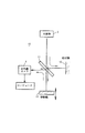
赤外スペクトルを測定する赤外線分光装置3として、フーリエ変換型赤外分光光度計を用いる。このフーリエ変換型赤外分光光度計10の原理を図2に示す。入射した赤外線をビームスプリッタ11で2つに分割し、一方の赤外線に対する反射鏡を固定鏡12とし、他方の赤外線に対する反射鏡を移動鏡13とする。
【0017】
これにより、分割された赤外線をそれぞれ固定鏡12と移動鏡13で反射させて、光路差を変化させて再度重ね合わせ、光路差で変化する干渉波形を作り、これを赤外線カメラ(赤外線検出器)で検出し、その干渉波形をフーリエ変換して、入射した赤外線の分光出力を計算で求め、赤外スペクトル放射強度又は赤外スペクトル反射率を測定する。
【0018】
なお、赤外スペクトル放射強度又は反射率は、プリズム、回折格子等を用いた周知の赤外分光光度計を用いて測定することも出来る。
【0019】
このような赤外スペクトル放射強度又は反射率の測定を、二次元的走査で行うことにより、対象物2の画像の二次元のxyの各位置における赤外スペクトル放射強度又は反射率分布を測定することができる。
【0020】
上記のフーリエ変換型赤外スペクトル検出において、結像光学系を用いて対象物2の画像スペクトル分布を、走査する事なしに同時に得ることも可能である。
【0021】
対象物2(例えば、顔料や染料、樹木等)の各色と、その赤外スペクトルの関連について、図3に示すような青、緑、赤の各色に対応する赤外スペクトル放射強度又は反射率を予め測定して取得し、この対応データをコンピュータ6の記憶装置7に記憶しておく。要するに色と、赤外スペクトル放射強度又は反射率のパターンを記憶装置7に記憶しておく。
【0022】
そして、対象物2から放射又は反射される赤外線を分光し赤外スペクトル放射強度又は赤外スペクトル反射率得て、コンピュータ6は、その記憶装置7に記憶された対象物の色と、赤外スペクトル放射強度又は赤外スペクトル反射率との対応データ(図3参照。)に基づいてパターン認識し色を決定できる。そして、この色を画像に着色することでカラー画像を形成することができる。
【0023】
対象物2の赤外スペクトル放射強度又は赤外スペクトル反射率を測定することで、その対象物2の色を判別するための別の手段について述べる。この別の手段では、対象物2(例えば、顔料や染料、樹木等)の可視領域スペクトル分布と、この可視スペクトル分布に対応する赤外スペクトル放射強度又は赤外スペクトル反射率をそれぞれ測定しておく。これを図4に示す。この図4において、可視領域スペクトルに対応する赤外スペクトル放射強度又は赤外スペクトル反射率を知り、図4(a)とこれに対応する図4(b)、そして図4(c)とこれに対応する図4(d)のように、可視光領域の各波長と、これに対応する赤外スペクトル強度のデータをコンピュータ6の記憶装置7に記憶しておく。
【0024】
そして、コンピュータ6は、その記憶装置7に記憶された対象物の可視スペクトルと、赤外スペクトル放射強度又は赤外スペクトル反射率との対応データ(図4参照。)に基づいて、可視スペクトル分布を推定し、色を確定できる。そして、その色情報により赤外線カメラで得た画像を着色する。
【0025】
なお、可視スペクトル色情報を決定する方法は従来の測色学の手段が利用出来る。また、効率的な赤外スペクトル分布と色情報の対応づけ手段としては、ニューラルネットワークを用いた学習法が利用できる。
【0026】
(実施例2)
図5は、本発明に係る赤外線カラー画像形成装置の実施例2を示すブロック図である。この実施例2は、波長の異なるいくつかの赤外線を実施例1のような赤外線分光装置で分光処理する煩雑さを無くす為、波長の異なる幾つかの赤外線を含む赤外線を対象物2に照射するとともに、その反射光を異なる波長の赤外光を受光する赤外線カメラで受光するものである。
【0027】
図5において、赤外線カラー画像形成装置14は、λ1用赤外線カメラ(受光手段)15、λ2用赤外線カメラ16及びλ3用赤外線カメラ17を備え、コンピュータ6は各波長用の赤外線カメラ15〜17からそれぞれ入力されるλ1用赤外線反射情報、λ2用赤外線反射情報及びλ3用赤外線反射情報を分析して色を確定し、ディスプレーでカラー画像を提供する。
【0028】
λ1用赤外線カメラ15は、波長λ1にピーク感度のある赤外線カメラからなっており、赤外線カメラの画像を得ると共に、波長λ1の赤外線反射強度又は反射率を得る。λ2用赤外線カメラ16は、波長λ2にピーク感度のある赤外線カメラからなっており、λ2の赤外線放射強度又は反射率を得る。λ3用赤外線カメラ17は、λ3にピーク感度のある赤外線カメラからなっており、波長λ3の赤外線放射強度又は反射率を得る。
【0029】
この実施例2では、コンピュータ6は、各対象物2についての色情報と、赤外スペクトル放射強度又は反射率との対応データを予め記憶している記憶装置を有している。さらに、コンピュータ6は、第1及び第2の処理手段を有している。第1の処理手段は、上記各赤外線カメラ毎で取得したλ1、λ2、λ3の各波長の画像に対する赤外スペクトル放射強度又は反射率を、上記色情報と赤外スペクトル放射強度又は反射率との対応データに基づいてパターン認識し、カラー情報を得る機能を有する。
【0030】
そして、第2の処理手段は、第1の処理手段で得たカラー情報を基に画像に着色を施す機能を有するものである。
【0031】
(実施例3)
図6は、本発明に係る赤外線カラー画像形成装置の実施例3を示すブロック図である。この実施例3の赤外線カラー画像形成装置18は、特定波長赤外線放射・受光手段を有する。この特定波長赤外線放射・受光手段は、複数の波長を時分割で順次放射する複数の赤外線光源と、対象物2からの反射光を受光する赤外線カメラ24とを備えている。
【0032】
赤外線光源装置は、複数の波長の赤外線を照射する複数の赤外線光源、例えば図6に示すように、λ1用赤外線光源19、λ2用赤外線光源20、λ3用赤外線光源21を備えている。そして、コンピュータ22は、対象物2に複数の波長の赤外線を時分割で照射するように制御する赤外線光源制御装置23を有しており、これらの複数の赤外線光源19〜21がコンピュータ22からの同期信号に同期して時分割で順次放射可能である。
【0033】
このように時分割で放射されたλ1、λ2、λ3の赤外線が対象物2で反射され、これを赤外線カメラ24で受光し、赤外スペクトル放射強度又は反射率の表現された画像として取り込むように構成されている。
【0034】
コンピュータ22は、各対象物2についての色情報と、赤外スペクトル放射強度又は反射率との対応データを予め記憶している記憶装置7を設けており、さらに画像のカラー情報を得る第1の処理手段8と、第1の処理手段で得たカラー情報を基に対象物2を人工的に着色を施す第2の処理手段9とを有している。
【0035】
上記赤外線カメラ24で受光した赤外線強度の表現された画像データを、コンピュータ22に入力し、第1の処理手段で、λ1、λ2、λ3の赤外線スペクトル放射強度又は反射率を、予め記憶装置7に記憶された対応データに基づいて、パターン認識して対象物2の色を確定し、第2の処理手段9で、画像に色を付けるデータ処理を行う。そして、ディスプレー25でカラー画像を視認することができる。
【0036】
(実施例4)
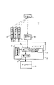
図7は、本発明に係る赤外線カラー画像形成装置の実施例4を示すブロック図である。この実施例4の赤外線カラー画像形成装置26は、複数の波長を含む赤外線を放射する赤外線光源装置27と、対象物2からの反射光を分光する赤外線分光フィルタ装置28と、赤外線分光フィルタ装置28で分光された赤外線を受光する赤外線カメラ29とから構成されている。
【0037】
そして、赤外線分光フィルタ装置28は、赤外線カメラの前の受光路中に設けられ、コンピュータ22のフィルタ切換制御装置30からの同期信号に同期して時分割で受光路中に置くように切換可能な複数のフィルタを有する。即ち、赤外線光源から放射される赤外線は、コンピュータ22のフィルタ切換制御装置30からの同期信号に同期して時分割で切り換えられるフィルタを通過し分光された、例えば、λ1、λ2、λ3の波長の赤外線を赤外線カメラで受光することが可能である。
【0038】
このように時分割で分光され受光されたλ1、λ2、λ3の赤外線を赤外線カメラ29で順次受光し、赤外スペクトル放射強度又は反射率で表現された画像として取り込むように構成されている。
【0039】
コンピュータ22は、各対象物2についての色情報と、赤外スペクトル放射強度又は反射率との対応データを予め記憶している記憶装置7を設けており、さらに画像のカラー情報を得る第1の処理手段8と、第1の処理手段で得たカラー情報を基に対象物2を人工的に着色を施す第2の処理手段9とを有している。
【0040】
上記赤外線カメラで受光した赤外線画像についてのλ1、λ2、λ3の赤外スペクトル放射強度又は反射率を処理手段8でコンピュータ22に入力し、λ1、λ2、λ3の赤外スペクトル放射強度又は反射率を、予め記憶装置に記憶された対応データに基づいてパターン認識し、対象物2の色を確定し、第2の処理手段で取り込んだ画像に色を付けるデータ処理を行う。ディスプレー25でカラー画像を視認することができる。
【0041】
以上本発明の実施の形態を実施例に基づいて説明したが、本発明は、特にこのような実施例に限定されるものではなく特許請求の範囲記載の技術的事項の範囲内でいろいろな実施例があることは言うまでもない。
【0042】
【発明の効果】
従来、赤外線カメラでは、赤外線強度画像しか得られず、たとえ赤外線カメラで着色画像を作っても、疑似カラーであるため、対象物の実際に近いカラー画像は期待できないという問題があったが、本発明に係る赤外線カラー画像形成装置計によれば、対象物について赤外線カメラで得た画像に、カラー情報を加えることができ、対象物の実際に近いカラー画像を得ることが可能である。
【図面の簡単な説明】
【図1】本発明に係る赤外線カラー画像形成装置の実施例1を示すブロック図である。
【図2】実施例1の赤外線分光装置として利用されるフーリエ変換型赤外分光光度計の原理を示す図である。
【図3】対象物に関する色別の赤外スペクトルの分布を示す図である。
【図4】対象物に関する可視スペクトル分布と赤外スペクトル分布の対応を示す図である。
【図5】本発明に係る赤外線カラー画像形成装置の実施例2を示すブロック図である。
【図6】本発明に係る赤外線カラー画像形成装置の実施例3を示すブロック図である。
【図7】本発明に係る赤外線カラー画像形成装置の実施例4を示すブロック図である。
【符号の説明】
1、14、18、26 赤外線カラー画像形成装置
2 対象物
3 赤外線分光装置
4、24、29 赤外線カメラ
5 赤外線光源
6、22 コンピュータ
7 記憶装置
8 第1の処理手段
9 第2の処理手段
10 フーリエ変換赤外分光光度計
11 ビームスプリッタ
23 赤外線光源制御装置
28 赤外線分光フィルタ装置
30 フィルタ切換制御装置[0001]
BACKGROUND OF THE INVENTION
The present invention acquires an image of an object with an infrared camera, detects an infrared radiation intensity or infrared reflectance value of the object, and obtains color information of the object from this value to form a color image. The present invention relates to an infrared color image forming apparatus.
[0002]
[Prior art]
Conventional infrared cameras can only obtain images having infrared intensity. As an image obtained with an infrared camera, there is an image obtained by coloring a human body temperature or an earth image by using a temperature range as color information. This type of color display video apparatus horizontally and vertically scans each point on the object to be measured, electrically detects infrared rays radiated from the object to be measured by an infrared detector, and a plurality of signals corresponding to the signal intensity. The gradation is colored, projected onto a display device such as a cathode ray tube as a pseudo color image, and the projected image is quantitatively and qualitatively measured and used for analysis or the like.
[0003]
[Problems to be solved by the invention]
Thus, conventionally, only an infrared intensity image can be obtained with an infrared camera. And even if a colored image is made with an infrared camera, since it is a pseudo color, a color image close to the actual object cannot be expected.
[0004]
The present invention aims to solve such conventional problems, and its specific problem is that by adding appropriate color information to an image obtained by an infrared camera for an object, An infrared color image forming apparatus capable of obtaining a color image close to the actual object is realized.
[0005]
[Means for Solving the Problems]
In order to solve the above problems, the present invention receives an infrared ray emitted or reflected from an object and obtains an infrared spectrum image, and the color, infrared spectrum radiant intensity or infrared of the object. Based on the correspondence data, a storage device that prestores the correspondence data with the spectral reflectance, and the infrared spectral radiant intensity or infrared spectral reflectance value at each position of the infrared spectral image. First processing means for determining a color at each position of the spectrum image; and second color for artificially coloring each position of the image of the object based on the color information obtained by the first processing means. And an infrared color image forming apparatus.
[0006]
Furthermore, in order to solve the above-mentioned problems, the present invention provides an infrared irradiation means for irradiating an object with infrared rays having different wavelengths, and a plurality of infrared cameras for separately receiving reflected light from the object and obtaining images, For the object, a storage device that stores in advance correspondence data between color and infrared spectrum radiant intensity or infrared spectral reflectance, and infrared spectrum radiant intensity or infrared for each wavelength acquired by each infrared camera. Based on the color information obtained by the first processing means for determining the color at each position of the infrared spectrum image based on the corresponding data from the value of the spectral reflectance, and the color information obtained by the first processing means, An infrared color image forming apparatus comprising: a second processing unit that artificially colors each position of an image of an object.
[0007]
Furthermore, in order to solve the above problems, the present invention provides a plurality of infrared irradiation means for irradiating an object with infrared rays having different wavelengths, and the plurality of infrared irradiation means when irradiating the object with infrared rays having different wavelengths. Infrared irradiation control means for controlling the infrared rays having different wavelengths to be irradiated in a time-sharing manner, and an infrared camera that receives reflected light of each wavelength of the infrared rays having different wavelengths from the object to obtain an image A storage device that stores in advance correspondence data of colors and infrared spectral radiant intensity or infrared spectral reflectance for the object; and infrared vector radiant intensity for each wavelength image acquired by the infrared camera. Or a first processing means for determining a color at each position of the infrared spectrum image based on the corresponding data from the value of the infrared vector reflectance, and the first An infrared color image forming apparatus comprising: a second processing unit that artificially colors each position of the image of the object based on color information obtained by the processing unit. .
[0008]
Furthermore, in order to solve the above-mentioned problems, the present invention receives, in a time division manner, an infrared irradiation means for irradiating an object with infrared rays having different wavelengths, and reflected light of each wavelength of the infrared rays with different wavelengths from the object. When receiving infrared rays having different wavelengths on the object and an infrared camera that obtains an image, the filters of the infrared spectral filter device are sequentially placed in the light receiving path, and control is performed so that infrared rays having different wavelengths are received in a time-sharing manner. Infrared filter switching control means, a storage device for preliminarily storing correspondence data of color and infrared spectrum radiant intensity or infrared spectrum reflectance for the object, and an image for each wavelength acquired by the infrared camera A first color for determining a color at each position of the infrared spectrum image based on the corresponding data from the infrared vector radiation intensity or the infrared vector reflectance. And a second processing means for artificially coloring each position of the image of the object based on the spectrum information obtained by the first processing means. An infrared color image forming apparatus is provided.
[0009]
Correspondence data between color and infrared spectral radiant intensity or infrared spectral reflectance is a distribution of each color and infrared spectral radiant intensity or infrared spectral reflectance, or spectral radiant intensity or reflectance in the visible region. And infrared spectrum radiant intensity or infrared spectrum reflectance.
[0010]
DETAILED DESCRIPTION OF THE INVENTION
DESCRIPTION OF THE PREFERRED EMBODIMENTS Embodiments of an infrared color image forming apparatus according to the present invention will be described based on examples with reference to the drawings.
[0011]
The basic idea of the present invention is to acquire data in which the color of an object is associated with the infrared spectrum radiant intensity or the infrared spectrum reflectance in advance, and the object is radiated and / or reflected red. An image obtained by measuring an outer spectrum with an infrared spectrophotometer, determining the color of the object based on the corresponding data, and adding a color to the object to obtain a color image. Forming device.
[0012]
Example 1
FIG. 1 is a block diagram showing the overall configuration of Embodiment 1 of an infrared color image forming apparatus according to the present invention. In the infrared color image forming apparatus 1 of this embodiment, the infrared radiation emitted from the object 2 (object to be measured) is dispersed by the
[0013]
Alternatively, infrared light having a wavelength distribution (having different wavelengths) is irradiated onto the
[0014]
For the
[0015]
The
[0016]
As the infrared
[0017]
Thereby, the divided infrared rays are reflected by the fixed
[0018]
The infrared spectrum radiant intensity or reflectance can also be measured using a known infrared spectrophotometer using a prism, a diffraction grating, or the like.
[0019]
By measuring the infrared spectrum radiant intensity or reflectance in a two-dimensional scan, the infrared spectrum radiant intensity or reflectance distribution at each two-dimensional xy position of the image of the
[0020]
In the Fourier transform infrared spectrum detection described above, it is also possible to simultaneously obtain the image spectrum distribution of the
[0021]
Regarding the relationship between each color of the object 2 (for example, pigment, dye, tree, etc.) and its infrared spectrum, the infrared spectrum radiant intensity or reflectance corresponding to each color of blue, green and red as shown in FIG. It is obtained by measuring in advance, and this correspondence data is stored in the
[0022]
Then, infrared rays emitted or reflected from the
[0023]
Another means for discriminating the color of the
[0024]
Then, the
[0025]
It should be noted that conventional colorimetric means can be used to determine the visible spectral color information. A learning method using a neural network can be used as means for efficiently associating infrared spectrum distribution with color information.
[0026]
(Example 2)
FIG. 5 is a block diagram showing Example 2 of the infrared color image forming apparatus according to the present invention. In the second embodiment, the
[0027]
In FIG. 5, the infrared color
[0028]
lambda 1 of
[0029]
In the second embodiment, the
[0030]
The second processing means has a function of coloring the image based on the color information obtained by the first processing means.
[0031]
(Example 3)
FIG. 6 is a block
[0032]
Infrared light source device includes a plurality of infrared light sources for irradiating infrared rays of a plurality of wavelengths, for example, as shown in FIG. 6, lambda 1 for the
[0033]
The infrared rays of λ 1 , λ 2 , and λ 3 radiated in a time division manner are reflected by the
[0034]
The
[0035]
The image data expressing the infrared intensity received by the
[0036]
Example 4
FIG. 7 is a block diagram showing Embodiment 4 of the infrared color image forming apparatus according to the present invention. The infrared color
[0037]
The infrared
[0038]
The infrared rays of λ 1 , λ 2 , and λ 3 that have been spectrally divided and received in this way are sequentially received by the infrared camera 29 and captured as an image expressed by infrared spectrum radiation intensity or reflectance. Yes.
[0039]
The
[0040]
The infrared spectrum radiant intensity or reflectance of λ 1 , λ 2 , λ 3 for the infrared image received by the infrared camera is input to the
[0041]
Although the embodiments of the present invention have been described based on examples, the present invention is not particularly limited to such examples, and various implementations can be made within the scope of the technical matters described in the claims. It goes without saying that there are examples.
[0042]
【The invention's effect】
Conventionally, an infrared camera can only obtain an infrared intensity image, and even if a colored image is created with an infrared camera, it is a pseudo color, so there is a problem that a color image close to the actual object cannot be expected. According to the infrared color image forming apparatus meter according to the invention, color information can be added to an image obtained by an infrared camera for an object, and a color image close to the actual object can be obtained.
[Brief description of the drawings]
FIG. 1 is a block diagram showing a first embodiment of an infrared color image forming apparatus according to the present invention.
FIG. 2 is a diagram illustrating the principle of a Fourier transform infrared spectrophotometer used as the infrared spectroscopic device of the first embodiment.
FIG. 3 is a diagram showing a distribution of infrared spectra by color for an object.
FIG. 4 is a diagram illustrating a correspondence between a visible spectrum distribution and an infrared spectrum distribution related to an object.
FIG. 5 is a block diagram showing Example 2 of an infrared color image forming apparatus according to the present invention.
FIG. 6 is a block diagram showing Example 3 of an infrared color image forming apparatus according to the present invention.
FIG. 7 is a block diagram showing Example 4 of the infrared color image forming apparatus according to the present invention.
[Explanation of symbols]
1, 14, 18, 26 Infrared color
Claims (1)
波長分布を有する前記赤外線を対象物に照射する赤外線照射手段と、
対象物から反射される赤外線を分光する赤外線分光装置と、
分光された赤外線を受光し、赤外スペクトル画像を検出する赤外線カメラと、
対象物について、色と、赤外スペクトル反射率のパターンとの対応データを予め記憶する記憶装置と、
前記赤外線照射手段で対象物に照射し、その反射光を前記赤外線分光装置で分光して赤外線カメラで検出した赤外スペクトル画像について、該画像の各位置における赤外スペクトル反射率のパターンから、前記対応データに基づいてパターン認識して、前記赤外スペクトル画像の各位置における色を決定する第1の処理手段と、
前記第1の処理手段で得た色情報を基に、前記対象物の画像の各位置に人工的に着色を施す第2の処理手段と、を備えており、
前記対応データは、予め前記赤外線照射手段で対象物に照射し、その反射光を前記赤外線分光装置で分光して赤外線カメラで検出した赤外スペクトル画像について、該画像の赤外スペクトル反射率のパターンを予め得て、該対象物の色と、予め得た赤外スペクトル反射率のパターンの対応データであることを特徴とする赤外線カラー画像形成装置。 By measuring the infrared spectral reflectance from the infrared rays irradiated and reflected by the two-dimensional scanning for the object, a two-dimensional spectrum image of the object is obtained, and each of the spectrum images is obtained. An infrared color image forming apparatus for artificially coloring a position,
An infrared irradiation means for irradiating an object with the infrared having a wavelength distribution;
An infrared spectroscopic device that splits infrared rays reflected from an object;
An infrared camera that receives the dispersed infrared light and detects an infrared spectrum image;
A storage device that stores in advance correspondence data between colors and infrared spectral reflectance patterns for the object;
For an infrared spectrum image that is irradiated onto an object with the infrared irradiation means, the reflected light is dispersed with the infrared spectrometer and detected with an infrared camera, from the pattern of infrared spectral reflectance at each position of the image, First processing means for recognizing a pattern based on corresponding data and determining a color at each position of the infrared spectrum image ;
Second processing means for artificially coloring each position of the image of the object based on the color information obtained by the first processing means ,
The correspondence data is a pattern of infrared spectral reflectance of an infrared spectral image that is pre-irradiated on an object with the infrared irradiating means, and the reflected light is dispersed with the infrared spectroscopic device and detected with an infrared camera. The infrared color image forming apparatus is obtained by preliminarily obtaining data corresponding to the color of the object and the infrared spectral reflectance pattern obtained in advance .
Priority Applications (1)
| Application Number | Priority Date | Filing Date | Title |
|---|---|---|---|
| JP2000363648A JP4782277B2 (en) | 2000-11-29 | 2000-11-29 | Infrared color image forming device |
Applications Claiming Priority (1)
| Application Number | Priority Date | Filing Date | Title |
|---|---|---|---|
| JP2000363648A JP4782277B2 (en) | 2000-11-29 | 2000-11-29 | Infrared color image forming device |
Publications (2)
| Publication Number | Publication Date |
|---|---|
| JP2002171519A JP2002171519A (en) | 2002-06-14 |
| JP4782277B2 true JP4782277B2 (en) | 2011-09-28 |
Family
ID=18834725
Family Applications (1)
| Application Number | Title | Priority Date | Filing Date |
|---|---|---|---|
| JP2000363648A Expired - Fee Related JP4782277B2 (en) | 2000-11-29 | 2000-11-29 | Infrared color image forming device |
Country Status (1)
| Country | Link |
|---|---|
| JP (1) | JP4782277B2 (en) |
Families Citing this family (13)
| Publication number | Priority date | Publication date | Assignee | Title |
|---|---|---|---|---|
| JP4080812B2 (en) * | 2002-08-09 | 2008-04-23 | 浜松ホトニクス株式会社 | System that can measure chromaticity in visible and invisible regions |
| JP2006109120A (en) | 2004-10-06 | 2006-04-20 | Funai Electric Co Ltd | Infrared imaging device |
| JP2007263829A (en) * | 2006-03-29 | 2007-10-11 | Jfe Steel Kk | Leakage monitoring method of co gas |
| JP5874116B2 (en) | 2009-07-30 | 2016-03-02 | 国立研究開発法人産業技術総合研究所 | Image photographing apparatus and image photographing method |
| TWI581638B (en) * | 2011-01-28 | 2017-05-01 | Yasushi Nagamune | Image photographing apparatus and image photographing method |
| JP6011778B2 (en) * | 2012-05-22 | 2016-10-19 | 株式会社富士通ゼネラル | Night vision imaging apparatus, infrared irradiation apparatus, and night vision imaging system |
| JP6055681B2 (en) | 2013-01-10 | 2016-12-27 | 株式会社 日立産業制御ソリューションズ | Imaging device |
| KR101604541B1 (en) * | 2014-07-21 | 2016-03-18 | 대진대학교 산학협력단 | Apparatus and Method for Reproduction of Color Image using Light of multi-wavelength |
| JP6260512B2 (en) * | 2014-10-24 | 2018-01-17 | 株式会社Jvcケンウッド | Imaging apparatus, imaging method, and imaging program |
| JP6361500B2 (en) * | 2014-12-24 | 2018-07-25 | ソニー株式会社 | Image processing apparatus, image processing method, and program |
| CN107431791B (en) * | 2015-03-31 | 2019-08-13 | 株式会社尼康 | Filming apparatus |
| JP6459808B2 (en) * | 2015-07-08 | 2019-01-30 | オムロン株式会社 | Image processing apparatus and traffic violation management system provided with the same |
| WO2017061432A1 (en) * | 2015-10-05 | 2017-04-13 | 株式会社ニコン | Imaging device and imaging program |
Family Cites Families (16)
| Publication number | Priority date | Publication date | Assignee | Title |
|---|---|---|---|---|
| JPS563033A (en) * | 1979-06-21 | 1981-01-13 | Olympus Optical Co | Endoscope device |
| JPS60164717A (en) * | 1984-02-07 | 1985-08-27 | Hamamatsu Photonics Kk | Direct viewing type observing device by artificial color |
| JPH0679594B2 (en) * | 1987-08-11 | 1994-10-12 | オリンパス光学工業株式会社 | Electronic endoscopic device |
| JPH047992A (en) * | 1990-04-25 | 1992-01-13 | Sony Corp | Dark color image pickup device |
| JPH0486075A (en) * | 1990-07-27 | 1992-03-18 | Mitsubishi Electric Corp | Infrared image pickup device |
| JPH04329340A (en) * | 1991-05-01 | 1992-11-18 | Tokyu Constr Co Ltd | Activity measuring method for plant |
| FI88768C (en) * | 1991-11-27 | 1993-06-28 | Valtion Teknillinen | Foerfarande och anordning Foer bildning av felfaergbild |
| JPH08293025A (en) * | 1995-04-20 | 1996-11-05 | Olympus Optical Co Ltd | Image sorting device |
| JPH0968466A (en) * | 1995-08-31 | 1997-03-11 | Toray Ind Inc | Method and device for measuring coloring concentration of fiber |
| US5903712A (en) * | 1995-10-05 | 1999-05-11 | Goss Graphic Systems, Inc. | Ink separation device for printing press ink feed control |
| JPH10148580A (en) * | 1996-11-19 | 1998-06-02 | Nippon Avionics Co Ltd | Method and device for monitoring temperature using pseudo color thermal image for alarm display |
| US5808303A (en) * | 1997-01-29 | 1998-09-15 | Art Aerospace Research Technologies Inc. | Infrared screening and inspection system |
| JPH11243538A (en) * | 1998-02-25 | 1999-09-07 | Nissan Motor Co Ltd | Visually recognizing device for vehicle |
| JP4039751B2 (en) * | 1998-10-20 | 2008-01-30 | 日本分光株式会社 | Image data collection microspectrophotometer |
| JP2000155379A (en) * | 1998-11-19 | 2000-06-06 | Konica Corp | Image processing method, printing method, image processor, printing device, image processing system, printing system, photographic film and camera |
| JP2001137828A (en) * | 1999-11-12 | 2001-05-22 | Takeshi Hashimoto | Method for judging kind of material of waste |
-
2000
- 2000-11-29 JP JP2000363648A patent/JP4782277B2/en not_active Expired - Fee Related
Also Published As
| Publication number | Publication date |
|---|---|
| JP2002171519A (en) | 2002-06-14 |
Similar Documents
| Publication | Publication Date | Title |
|---|---|---|
| US6690466B2 (en) | Spectral imaging system | |
| RU2535640C2 (en) | Forming multispectral images | |
| JP4782277B2 (en) | Infrared color image forming device | |
| US10161796B1 (en) | LED lighting based multispectral imaging system for color measurement | |
| Cao et al. | A prism-mask system for multispectral video acquisition | |
| US11436871B2 (en) | Living body determination device, living body determination method, and living body determination program | |
| US7276719B2 (en) | Device for a goniometric examination of the optical properties of surfaces | |
| RU2457447C2 (en) | Apparatus and method of testing hair sample | |
| US7692784B2 (en) | Apparatus and methods relating to enhanced spectral measurement systems | |
| US7180588B2 (en) | Devices and method for spectral measurements | |
| US7433055B2 (en) | Device for the examination of optical properties of surfaces | |
| US7189984B2 (en) | Object data input apparatus and object reconstruction apparatus | |
| Du et al. | A prism-based system for multispectral video acquisition | |
| KR101604424B1 (en) | Apparatus for Measuring Luminance and Chrominance Distribution | |
| US6556706B1 (en) | Three-dimensional surface profile imaging method and apparatus using single spectral light condition | |
| KR20130103821A (en) | Image capturing device and image capturing method | |
| JP6917761B2 (en) | Image inspection equipment | |
| US20150098092A1 (en) | Device and Method For the Simultaneous Three-Dimensional Measurement of Surfaces With Several Wavelengths | |
| CN107076611A (en) | Spectrum imaging method and system | |
| CN103630240A (en) | Object surface color measuring device and method | |
| US10616458B2 (en) | Imaging apparatus and image processing method | |
| US3508051A (en) | Employing a plurality of dichroic mirrors to produce a three-color image | |
| JPH11326057A (en) | Measuring method and device for three-dimensional object | |
| JP2000009440A (en) | Method and device for measuring 3-dimensional object | |
| JP4672498B2 (en) | Concrete degradation factor detection method and detection apparatus |
Legal Events
| Date | Code | Title | Description |
|---|---|---|---|
| A621 | Written request for application examination |
Free format text: JAPANESE INTERMEDIATE CODE: A621 Effective date: 20070919 |
|
| A977 | Report on retrieval |
Free format text: JAPANESE INTERMEDIATE CODE: A971007 Effective date: 20100610 |
|
| A131 | Notification of reasons for refusal |
Free format text: JAPANESE INTERMEDIATE CODE: A131 Effective date: 20100622 |
|
| A521 | Request for written amendment filed |
Free format text: JAPANESE INTERMEDIATE CODE: A523 Effective date: 20100805 |
|
| A521 | Request for written amendment filed |
Free format text: JAPANESE INTERMEDIATE CODE: A523 Effective date: 20100805 |
|
| TRDD | Decision of grant or rejection written | ||
| A01 | Written decision to grant a patent or to grant a registration (utility model) |
Free format text: JAPANESE INTERMEDIATE CODE: A01 Effective date: 20110705 |
|
| A01 | Written decision to grant a patent or to grant a registration (utility model) |
Free format text: JAPANESE INTERMEDIATE CODE: A01 |
|
| A61 | First payment of annual fees (during grant procedure) |
Free format text: JAPANESE INTERMEDIATE CODE: A61 Effective date: 20110707 |
|
| FPAY | Renewal fee payment (event date is renewal date of database) |
Free format text: PAYMENT UNTIL: 20140715 Year of fee payment: 3 |
|
| R150 | Certificate of patent or registration of utility model |
Free format text: JAPANESE INTERMEDIATE CODE: R150 |
|
| R250 | Receipt of annual fees |
Free format text: JAPANESE INTERMEDIATE CODE: R250 |
|
| S531 | Written request for registration of change of domicile |
Free format text: JAPANESE INTERMEDIATE CODE: R313531 |
|
| R350 | Written notification of registration of transfer |
Free format text: JAPANESE INTERMEDIATE CODE: R350 |
|
| LAPS | Cancellation because of no payment of annual fees |