JP4777093B2 - Motor drive device and electric apparatus using the same - Google Patents
Motor drive device and electric apparatus using the same Download PDFInfo
- Publication number
- JP4777093B2 JP4777093B2 JP2006055227A JP2006055227A JP4777093B2 JP 4777093 B2 JP4777093 B2 JP 4777093B2 JP 2006055227 A JP2006055227 A JP 2006055227A JP 2006055227 A JP2006055227 A JP 2006055227A JP 4777093 B2 JP4777093 B2 JP 4777093B2
- Authority
- JP
- Japan
- Prior art keywords
- inertia
- moment
- drive motor
- motor
- correction amount
- Prior art date
- Legal status (The legal status is an assumption and is not a legal conclusion. Google has not performed a legal analysis and makes no representation as to the accuracy of the status listed.)
- Active
Links
Images


Landscapes
- Control Of Washing Machine And Dryer (AREA)
- Control Of Motors That Do Not Use Commutators (AREA)
Description
本発明は、モータを駆動制御するためのモータ駆動装置に関し、さらには、この駆動装置を用いた洗濯機、洗濯乾燥機等の電気機器に関するものである。 The present invention relates to a motor driving device for driving and controlling a motor, and further relates to an electric device such as a washing machine and a washing / drying machine using the driving device.
洗濯機または洗濯乾燥機は、洗濯槽に注ぐ水量や洗濯槽を回転させるための駆動モータの回転トルク等を設定するために、始動時に洗濯槽に収容された洗濯物の容量を判定する必要がある。そこで、特許文献1では、ベクトル制御によってトルク電流を制御し、出力トルクと回転数の関係から慣性モーメントを求め、慣性モーメントと容量の関係から洗濯槽内に収容された収容物の容量を判定する方法が開示されている。
ところで、駆動モータを制御するには、駆動モータの巻線抵抗やインダクタンス等のモータ定数からトルク電流を演算し、駆動モータを制御する電流センサレスベクトル制御がある。 By the way, in order to control the drive motor, there is current sensorless vector control for controlling the drive motor by calculating a torque current from motor constants such as winding resistance and inductance of the drive motor.
しかし、この電流センサレスベクトル制御で用いるモータ定数は、駆動モータの精度や温度変化等によって変化する。そのため、モータ定数と実際の定数値が異なり、出力電圧にずれが生じて出力トルクに必要なトルク電流が得られない問題がある。また、駆動モータへの出力電圧が指令電圧と異なり、出力トルクが変わってしまう問題もある。 However, the motor constant used in this current sensorless vector control varies depending on the accuracy of the drive motor, temperature change, and the like. Therefore, there is a problem that the motor constant is different from the actual constant value, and the output voltage is deviated and a torque current necessary for the output torque cannot be obtained. Further, there is a problem that the output torque to the drive motor is different from the command voltage and the output torque is changed.
そこで、本発明は、上記に鑑み、駆動モータの動作状況から、収容された収容物の容量を正確に判定できる簡易的な構造のモータ駆動装置の提供を目的とする。 In view of the above, an object of the present invention is to provide a motor drive device having a simple structure that can accurately determine the capacity of a stored item from the operation state of the drive motor.
上記目的を達成するために、本発明では、収容物を収容する容器を回転させるための駆動モータに印加電圧を出力するインバータ回路と、前記インバータ回路を制御する制御装置と、前記駆動モータの動作状況を検出する動作状況検出手段とを備え、前記制御装置は、前記駆動モータの動作状況に基づいて、前記駆動モータの回転数から演算された前記容器の慣性モーメントを補正することを特徴とする。 In order to achieve the above object, according to the present invention, an inverter circuit that outputs an applied voltage to a drive motor for rotating a container that contains a stored item, a control device that controls the inverter circuit, and an operation of the drive motor Operating condition detecting means for detecting the condition, and the control device corrects the moment of inertia of the container calculated from the rotational speed of the drive motor based on the operation condition of the drive motor. .
ここで、動作状況とは、例えば、駆動モータが回転駆動させるための容器の大きさ、駆動モータを動作させている環境(外気温や湿度等)、あるいは、駆動モータやモータ駆動装置そのもののばらつきによる動作の変動等である。 Here, the operation status refers to, for example, the size of the container for the drive motor to rotate, the environment in which the drive motor is operated (outside temperature, humidity, etc.), or variations in the drive motor and the motor drive device itself. The fluctuation of the operation due to
動作状況検出手段は、これらの動作状況を、例えば、インバータ回路の電源電圧、駆動モータの巻線温度、あるいは、駆動モータのモータケースの温度等を検出し、検出結果から駆動モータの動作状況を判断する。 The operation status detection means detects these operation statuses, for example, the power supply voltage of the inverter circuit, the winding temperature of the drive motor, or the temperature of the motor case of the drive motor, and the operation status of the drive motor is detected from the detection result. to decide.
上記構成のモータ駆動装置は、駆動モータの回転数から慣性モーメントを演算し、演算した慣性モーメントに対して駆動モータの動作状況に応じた補正を行なっている。これにより、慣性モーメントは、駆動モータの動作状況に関係なく正確な値を算出することができる。 The motor drive device having the above configuration calculates the moment of inertia from the rotational speed of the drive motor, and corrects the calculated moment of inertia according to the operating condition of the drive motor. Thus, an accurate value of the moment of inertia can be calculated regardless of the operation state of the drive motor.
モータ駆動装置の具体的な構成としては、収容物を収容する容器を回転させるための駆動モータに印加電圧を出力するインバータ回路と、前記インバータ回路を制御する制御装置と、前記駆動モータの動作状況を検出する動作状況検出手段とを備え、前記制御装置は、前記駆動モータの回転数から前記容器の慣性モーメントを演算する慣性モーメント演算手段と、検出された前記駆動モータの動作状況に基づいて前記慣性モーメントを補正する慣性モーメント補正手段と、前記補正された慣性モーメントから前記容器に収容された収容物の容量を判定する判定手段とを備える。 As a specific configuration of the motor drive device, an inverter circuit that outputs an applied voltage to a drive motor for rotating a container that contains a stored item, a control device that controls the inverter circuit, and an operation state of the drive motor The control device is configured to calculate an inertia moment of the container from the rotational speed of the drive motor, and based on the detected operation status of the drive motor. Inertia moment correcting means for correcting the inertia moment, and determination means for determining the capacity of the container accommodated in the container from the corrected inertia moment.
駆動モータの動作状況に基づいて前記慣性モーメントを補正する慣性モーメント補正手段を備えることで、駆動モータに取り付けられた容器に収容された収容物の慣性モーメントを求める際、駆動モータの動作状況によって生じる慣性モーメントの誤差をなくすことができる。これにより、モータ動作状況によらず、正確な慣性モーメントを算出することができる。 Providing an inertia moment correction means for correcting the inertia moment based on the operation state of the drive motor, it is caused by the operation state of the drive motor when obtaining the inertia moment of the container accommodated in the container attached to the drive motor. The error of the moment of inertia can be eliminated. As a result, an accurate moment of inertia can be calculated regardless of the motor operating condition.
そこで、動作状況検出手段としてインバータ回路の電源電圧を検出する電源電圧検出手段を備え、慣性モーメント補正手段が前記電源電圧から慣性モーメントの補正量を演算することを特徴とする。 In view of this, the present invention is characterized in that a power supply voltage detection means for detecting the power supply voltage of the inverter circuit is provided as the operation status detection means, and the inertia moment correction means calculates a correction amount of the inertia moment from the power supply voltage.
演算された慣性モーメントを補正量によって補正することにより、インバータ回路の電源電圧の増減とは関係なく、正確な慣性モーメントに基づいて収容物の容量を判定することができる。 By correcting the calculated moment of inertia with the correction amount, the capacity of the accommodation can be determined based on the accurate moment of inertia regardless of the increase or decrease of the power supply voltage of the inverter circuit.
また、駆動モータは、動作状況検出手段として駆動モータの巻線温度を検出する巻線温度検出手段を備え、慣性モーメント補正手段が検出した前記駆動モータの巻線温度から慣性モーメントの補正量を演算することを特徴とする。 The drive motor also includes winding temperature detection means for detecting the winding temperature of the drive motor as operation status detection means, and calculates a correction amount of the inertia moment from the winding temperature of the drive motor detected by the inertia moment correction means. It is characterized by doing.
演算された慣性モーメントを補正量によって補正することにより、駆動モータの巻線温度の変化とは関係なく、正確な慣性モーメントに基づいて収容物の容量を判定することができる。 By correcting the calculated moment of inertia with the correction amount, the capacity of the container can be determined based on the accurate moment of inertia regardless of the change in the winding temperature of the drive motor.
また、駆動モータは、駆動モータがモータケースに内装され、動作状況検出手段として前記モータケース内の温度を検出するモータケース温度検出装置を備え、慣性モーメント補正手段が検出した前記モータケースの温度から慣性モーメントの補正量を演算することを特徴とする。 Further, the drive motor includes a motor case temperature detection device that detects the temperature in the motor case as an operation state detection means, and is provided from the temperature of the motor case detected by the inertia moment correction means. A correction amount of the moment of inertia is calculated.
演算された慣性モーメントを補正量によって補正することにより、モータケースの温度変化によって生じる駆動モータの巻線抵抗の変化とは関係なく、正確な慣性モーメントに基づいて収容物の容量を判定することができる。なお、モータケース温度検出手段は、モータケース外部の温度、モータケースの温度、または、モータケース内部の温度のいずれかを測定するが、特に好適には、モータケース内部の温度を測定することが良い。 By correcting the calculated moment of inertia with the correction amount, the capacity of the package can be determined based on the accurate moment of inertia regardless of the change in the winding resistance of the drive motor caused by the temperature change of the motor case. it can. The motor case temperature detecting means measures either the temperature outside the motor case, the temperature of the motor case, or the temperature inside the motor case, but it is particularly preferable to measure the temperature inside the motor case. good.
また、慣性モーメント補正手段は、製品ごとに定められるばらつき補正量に基づいて、慣性モーメントを補正することを特徴とする。 Further, the inertia moment correction means corrects the moment of inertia based on a variation correction amount determined for each product.
ここで、製品ごとに定められるばらつきとは、製造許容範囲内で製造されることで生じる各モータ駆動装置の誤差、あるいは、組み立て時における取り付けによって生じる誤差等である。このばらつきは、基準となる駆動モータを動作させたときに得られる慣性モーメントを基準値とし、駆動モータを動作させたときの慣性モーメントと基準値とから演算される。 Here, the variation determined for each product is an error of each motor driving device caused by being manufactured within the allowable manufacturing range or an error caused by attachment at the time of assembly. This variation is calculated from the moment of inertia and the reference value when the drive motor is operated with the moment of inertia obtained when the reference drive motor is operated as a reference value.
上記構成によると、モータ駆動装置は、動作手段によって回転した駆動モータの回転数から慣性モーメントを演算する。慣性モーメント補正手段は、演算された慣性モーメントからばらつき補正量を演算する。 According to the above configuration, the motor drive device calculates the moment of inertia from the rotational speed of the drive motor rotated by the operating means. The inertia moment correction means calculates a variation correction amount from the calculated inertia moment.
具体的には、慣性モーメント補正手段によって、基準となる駆動モータを動作させたときに得られる慣性モーメントを基準値とし、動作手段によって駆動モータを動作させたときの慣性モーメントと基準値とからばらつき補正量を演算する。 Specifically, the inertia moment obtained when the reference drive motor is operated by the inertia moment correction means is used as a reference value, and the inertia moment when the drive motor is operated by the operation means is varied from the reference value. Calculate the correction amount.
ここで、基準慣性モーメントとは、各部品が規格通りに製造されたモータ駆動装置が動作したときに得られる慣性モーメントである。 Here, the reference moment of inertia is a moment of inertia obtained when a motor driving device in which each part is manufactured according to the standard operates.
演算された慣性モーメントをばらつき補正量によって補正することにより、駆動モータや容器等のばらつきとは関係なく、正確な慣性モーメントに基づいて収容物の容量を判定することができる。 By correcting the calculated moment of inertia with the variation correction amount, the capacity of the contained item can be determined based on the accurate moment of inertia regardless of variations in the drive motor, container, and the like.
また、動作手段は、容器に収容物が入っていないときに駆動モータを回転させることを特徴とする。容器に収容物が入っていない状態で駆動モータを回転させることで、収容物や周辺環境等の補正動作実施条件が常に同じ条件となる。そのため、慣性モーメント補正手段は、収容物に依存することなく、モータ駆動装置ごとのばらつき補正量を正確に演算することができる。 Further, the operating means is characterized in that the drive motor is rotated when no container is in the container. By rotating the drive motor in a state in which no container contains anything, the correction operation execution conditions such as the contents and the surrounding environment are always the same. Therefore, the moment of inertia correction means can accurately calculate the variation correction amount for each motor drive device without depending on the contents.
また、ばらつき補正量が閾値を超えるか否かを検出する異常検出手段を備え、異常検出手段は、前記ばらつき補正量が閾値を超えた場合、異常と判断することを特徴とする。この場合、モータ駆動装置の異常と判断し、装置の組み立て直しや整備点検等をする。ばらつき補正量が閾値を超えない場合は、演算された慣性モーメントをばらつき補正量によって補正し、補正された慣性モーメントから収容物の容量を判定する。 Further, an abnormality detection unit is provided for detecting whether or not the variation correction amount exceeds a threshold value, and the abnormality detection unit determines that an abnormality is present when the variation correction amount exceeds the threshold value. In this case, it is determined that the motor drive device is abnormal, and the device is reassembled or serviced. When the variation correction amount does not exceed the threshold value, the calculated moment of inertia is corrected by the variation correction amount, and the capacity of the contained item is determined from the corrected inertia moment.
また、上記の電源電圧、巻線温度、モータケース温度、基準慣性モーメントとの差から求めた補正量のうちいずれか1つあるいは複数を加えて、慣性モーメントを補正してもよい。これにより、正確な容量判定をすることができる。 Further, the moment of inertia may be corrected by adding any one or a plurality of correction amounts obtained from the differences from the power supply voltage, the winding temperature, the motor case temperature, and the reference moment of inertia. Thereby, an accurate capacity determination can be performed.
また、上記記載のモータ駆動装置を電気機器、例えば、洗濯機または洗濯乾燥機に備えたことを特徴とする。この構成により、慣性モーメントから容器に収容された容量を検知する洗濯機もしくは洗濯乾燥機においては、慣性モーメントの演算精度が高くすることができるので容量の判定精度が向上する。この結果、洗剤の投入量を正確にユーザに伝えることができると同時に、容量に応じて洗濯動作を変化させ、容量に最も適した洗濯動作の実現が可能となる。 Further, the motor drive device described above is provided in an electric device, for example, a washing machine or a washing / drying machine. With this configuration, in a washing machine or a washing / drying machine that detects the capacity accommodated in the container from the moment of inertia, the calculation accuracy of the moment of inertia can be increased, so that the capacity determination accuracy is improved. As a result, it is possible to accurately notify the user of the amount of detergent to be introduced, and at the same time, it is possible to change the washing operation according to the capacity and to realize the washing operation most suitable for the capacity.
本発明によると、インバータ回路の電源電圧、駆動モータの巻線温度、モータケース内温度等の駆動モータの動作状況から慣性モーメントの補正量を算出することができる。また、製品ごとのばらつきがある場合でも、そのばらつきの影響を受けることなく慣性モーメントの補正量を演算することができる。 According to the present invention, the correction amount of the moment of inertia can be calculated from the operation state of the drive motor such as the power supply voltage of the inverter circuit, the winding temperature of the drive motor, and the temperature in the motor case. Further, even if there is a variation for each product, the correction amount of the moment of inertia can be calculated without being affected by the variation.
このような補正を可能とすることにより、慣性モーメントの演算精度が高くすることができる。そのため、収容物の容量を正確に検出でき、さらに、駆動モータにより駆動される電気機器の運動制御を正確に伝えることができる。特に、洗濯機や洗濯乾燥機に適用することにより、多様な運転に対応でき、電気機器の性能向上につながる。 By enabling such correction, the calculation accuracy of the moment of inertia can be increased. Therefore, it is possible to accurately detect the capacity of the stored item, and to accurately transmit the motion control of the electric device driven by the drive motor. In particular, by applying it to a washing machine and a washing / drying machine, it is possible to cope with a variety of operations and to improve the performance of electrical equipment.
[第1実施形態]
以下、本発明の第1実施形態について図1〜図5に基づいて詳細に説明する。第1実施形態に係るモータ駆動装置は、電気機器に搭載された3相ブラシレスモータである駆動モータ1をインバータ回路2によるインバータ制御によって駆動制御する。なお、電気機器は、収容物を収容する容器に直接駆動モータ1を取り付けたダイレクトドライブ方式を採用する。
[First Embodiment]
Hereinafter, a first embodiment of the present invention will be described in detail with reference to FIGS. The motor drive device according to the first embodiment drives and controls a
インバータ回路2は、制御装置としてのマイクロコンピュータ3(以下、マイコン3とする)から印加電圧信号が供給され、この信号に基づいて駆動モータ1に印加電圧を出力する。
The
駆動モータ1は、極対数を10とされる。また、駆動モータ1は、モータケース1aに内装される。さらに、駆動モータ1には、ロータの位置を検出するロータ位置検出部4と、駆動モータ1の巻線の温度を検出する巻線温度検出部16とが設けられる。
The
ロータ位置検出部4は、永久磁石のN極とS極との入れ替わりの瞬間を検出するホールセンサを有している。ホールセンサは、電気角120度間隔で3個配置されている。1個のホールセンサによって駆動モータ1の機械角36degの回転を検出できる。したがって、3個の各ホールセンサにより6通りの組み合わせが得られ、ロータ位置検出部4は、駆動モータ1の回転位置を機械角6degごとに検出して、磁極位置信号をマイコン3に出力する。
The rotor
巻線温度検出部16は、駆動モータ1の内部に備えられており、駆動モータ1のコイル端子のうちいずれか1つの特定相の巻線温度を検出する。巻線温度検出部16は、検出した駆動モータ1の巻線温度をマイコン3に出力する。
The winding
マイコン3は、洗濯機に対する操作によって入力された指令モータ回転数、あるいは、指令トルクに基づいて駆動モータ1を駆動制御するとともに、運転中は、界磁電流に基づいて駆動モータ1を駆動制御する。これらの制御は、プログラムにしたがってソフト的に行われる。
The
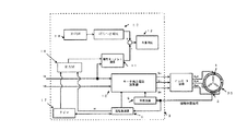
ここで、モータ駆動装置は、駆動モータ1を駆動制御するために、駆動モータ1のロータ位置を検出するロータ位置検出手段と、検出されたロータ位置から駆動モータ1の回転角度を演算する回転角度演算手段と、検出されたロータ位置から駆動モータ1の回転数を演算するモータ回転数演算手段と、回転角度とモータ回転数とからインバータ回路2に出力する印加電圧信号を演算するモータ出力電圧演算手段と、モータ回転数と駆動モータ1の電流をdq軸からなる2相電圧に変換した際のトルク電流Iqとから同期駆動モータ1に備えられた容器の慣性モーメントJを演算する慣性モーメント演算手段と、駆動モータ1の動作状況を検出する動作状況検出手段と、検出された駆動モータの動作状況に基づいて慣性モーメントJの補正する慣性モーメント補正手段と、補正された慣性モーメントから容器に収容された収容物の容量を判定する判定手段とを備える。
Here, the motor drive device is configured to detect the rotor position of the
動作状況検出手段は、2つの検出手段によって駆動モータ1の動作状況を検出する。第1検出手段は、インバータ回路2の電源電圧を検出する電源電圧検出手段である電源電圧検出部14である。電源電圧検出部14は、インバータ回路2内の電源電圧を検出する。第2検出手段は、駆動モータ1の巻線の温度を検出する巻線温度検出手段である巻線温度検出部16である。なお、ロータ位置検出手段は、ロータ位置検出部4である。
The operation state detection unit detects the operation state of the
マイコン3は、回転角度演算手段である回転角度演算部5と、モータ回転数演算手段である回転数演算部6と、モータ出力電圧演算手段であるモータ出力電圧演算部7と、慣性モーメント演算手段である慣性モーメント演算部11と、慣性モーメント補正手段である電源電圧補正演算部13および巻線温度補正演算部15と、判定手段である容量判定部12と、時間測定をするタイマ17と、データを記憶するメモリであるRAM18およびROM19とを備える。
The
モータ回転数演算部6は、ロータ位置検出部4から出力された磁極位置信号の検出間隔を計測し、計測された時間から駆動モータ1の回転数を演算する。各ホールセンサの検出間隔は一定であり、磁極切り替わり位置を検出した瞬間の駆動モータ1の回転角度を6degごとに検知できる。ここで、6deg以外の角度を得るためには、ホールセンサの磁極位置信号の間隔を計測することにより、磁極位置信号の無い時間でのモータ回転数と回転角度を演算する。
The motor rotation
例えば、同一のホールセンサにおいては、駆動モータ1が機械角36deg回転するのに経過した時間を測定することにより回転数を演算できる。3個のホールセンサの場合は、駆動モータ1が機械角6deg回転するのに必要とした時間からもモータ回転数の演算は可能である。
For example, in the same Hall sensor, the rotation speed can be calculated by measuring the time elapsed for the
回転角度演算部5は、ロータ位置検出部4から入力された磁極位置信号とモータ回転数演算部6によって演算されたモータ回転数とに基づいて駆動モータ1の回転角度を演算する。詳しくは、駆動モータ1に配設された3個のホールセンサの内いずれか1つが検出した磁極切り替わり位置を基準位置とし、この基準位置から、現在検出された磁極切り替わり位置までの経過時間と演算されたモータ回転数とに基づいて駆動モータ1の回転角度を演算する。
The rotation
本実施形態のマイコン3では、ホールセンサの磁極位置信号の出力変化を最小時間の管理である2μsecごとの整数倍の時間間隔で検出する。この検出したホールセンサの信号検出間隔時間を用いてモータ回転数を演算している。
In the
モータ出力電圧演算部7は、駆動モータ1の電流をdq軸からなる2相電圧に変換した際の界磁電流Idと、駆動モータ1の電流をdq軸からなる2相電圧に変換した際のトルク電流Iqと、モータ回転数演算部6で演算されたモータ回転数と、回転角度演算部5で演算された回転角度とに基づいて印加電圧信号を演算し、演算した印加電圧信号をインバータ回路2に出力する。
The motor output
慣性モーメント演算部11は、モータ回転数と駆動モータ1の電流をdq軸からなる2相電圧に変換した際のトルク電流Iqとから容器の慣性モーメントJを演算する。電源電圧補正演算部13は、電源電圧検出部14によって検出されたインバータ回路2の電源電圧に基づいて、慣性モーメント演算部11で演算された慣性モーメントJの補正量を演算する。巻線温度補正演算部15は、巻線温度検出部16によって検出された駆動モータ1の巻線温度に基づいて、慣性モーメント演算部11で演算された慣性モーメントJの補正量を演算する。
The inertia moment calculator 11 calculates the inertia moment J of the container from the motor rotation speed and the torque current Iq when the current of the
容量判定部12は、慣性モーメント演算部11で演算された慣性モーメントJに、巻線温度から演算された補正量、電源電圧から演算された補正量のうちいずれか一方あるいは両方を加算した慣性モーメントJmから容器の容量を判定する。
The
次に、慣性モーメントJの演算手法について説明する。この慣性モーメントJの演算手法は、次のような駆動モータ1を駆動するための電圧の関係式を用いる。なお、3相モータ1の電圧をdq軸からなる2相電圧に変換したときのd軸の電圧をVd、q軸の電圧をVqとする。
Next, a method for calculating the moment of inertia J will be described. This inertia moment J calculation method uses the following voltage relational expression for driving the
Vd=(R×Id)−(ω×Lq×Iq) (1)
Vq=(ω×Ld×Id)+(R×Iq)+(ω×Φ) (2)
Idは駆動モータ1の電流をdq軸からなる2相電圧に変換した際の界磁電流、Iqは駆動モータ1の電流をdq軸からなる2相電圧に変換した際のトルク電流、LqおよびLdは駆動モータ1のインダクタンス、Rは駆動モータ1の巻線抵抗、ωは駆動モータ1の角速度、Φは駆動モータ1の永久磁石による鎖交磁束数を示す。
Vd = (R × Id) − (ω × Lq × Iq) (1)
Vq = (ω × Ld × Id) + (R × Iq) + (ω × Φ) (2)
Id is a field current when the current of the
ここで、(1)式および(2)式において、Lq、Ld、R、Φといったモータ定数は、駆動モータ1自体の固有値であるため、変更することができない。また、角速度ωは、ホールセンサからの磁極位置信号に基づいて演算したモータ回転数を流用する。しかし、モータ回転数は、駆動モータ1に電圧を印加して回転させた結果であるため、任意に設定することができない。したがって、指令電圧であるd軸の電圧Vdとq軸の電圧Vqは、界磁電流指令Idとトルク電流Iqで制御される。
Here, in the equations (1) and (2), the motor constants such as Lq, Ld, R, and Φ are eigenvalues of the
また、駆動モータ1の出力トルクTとモータ電流との関係は、
T=P×{(Φ×Iq)+(Ld−Lq)×Id×Iq} (3)
となる。Pは極対数である。
The relationship between the output torque T of the
T = P × {(Φ × Iq) + (Ld−Lq) × Id × Iq} (3)
It becomes. P is the number of pole pairs.
ここで、駆動モータ1が起動する時には、界磁電流がId=0となるので、この値を(3)式に代入すると、
T=P×Φ×Iq (4)
となる。すなわち、駆動モータ1を起動するとき、駆動モータ1の出力トルクTは、トルク電流Iqのみで決定することができる。また、出力トルクTとモータ回転数rとの関係は、
T−Tr=J×(dr/dt) (5)
となる。なお、Trは負荷トルク、Jは慣性モーメント、dr/dtは駆動モータ1の加速度を示す。
Here, when the
T = P × Φ × Iq (4)
It becomes. That is, when starting the
T−Tr = J × (dr / dt) (5)
It becomes. Note that Tr represents load torque, J represents moment of inertia, and dr / dt represents acceleration of the
ここで、駆動モータ1の加速時の出力トルクをT(+)に制御し、減速時の出力トルクをT(−)に制御し、それぞれの測定したトルク電流をIq(+)、Iq(−)、回転加速度をω(+)、ω(−)として、(4)式に代入すると、
T(+)=P×Φ×Iq(+) (6)
T(−)=P×Φ×Iq(−) (7)
となり、(5)式に代入すると、
T(+)−Tr=J×(dω(+)/dt) (8)
T(−)−Tr=J×(dω(−)/dt) (9)
となる。駆動モータ1の加減速時において、負荷トルクTrが殆ど変化しないとすれば、(8)式、(9)式より、
T(+)−T(−)=J×{(dω(+)/dt)−(dω(−)/dt)} (10)
となる。したがって、慣性モーメントJは、
J={T(+)−T(−)}/{(dω(+)/dt)−(dω(−)/dt)} (11)
となり、この(11)式に(6)式および(7)式を代入すると
J={P×Φ×(Iq(+)−Iq(−))}/{(dω(+)/dt)−(dω(−)/dt)} (12)
となる。この(12)式において、極対数Pと鎖交磁束数Φは駆動モータ1の固有値であり、加速時の加速トルク電流Iq(+)と減速時の減速トルク電流Iq(−)は任意に設定することが可能な指令値である。すなわち、駆動モータ1の加速区間と減速区間の加速度を検出することで慣性モーメントJが演算できる。
Here, the output torque at the time of acceleration of the
T (+) = P × Φ × Iq (+) (6)
T (−) = P × Φ × Iq (−) (7)
And substituting into equation (5),
T (+) − Tr = J × (dω (+) / dt) (8)
T (−) − Tr = J × (dω (−) / dt) (9)
It becomes. If the load torque Tr hardly changes at the time of acceleration / deceleration of the
T (+) − T (−) = J × {(dω (+) / dt) − (dω (−) / dt)} (10)
It becomes. Therefore, the moment of inertia J is
J = {T (+) − T (−)} / {(dω (+) / dt) − (dω (−) / dt)} (11)
When substituting the equations (6) and (7) into the equation (11), J = {P × Φ × (Iq (+) − Iq (−))} / {(dω (+) / dt) − (Dω (−) / dt)} (12)
It becomes. In this equation (12), the number of pole pairs P and the number of flux linkages Φ are eigenvalues of the
ここで、(dω(+)/dt)と(dω(−)/dt)は、駆動モータ1の回転数ωの時間微分であるから、微小時間での回転数の変化として表すことができる。そこで、加速区間の開始回転数をω1、終了回転数をω2、経過時間をt1とし、減速区間の開始回転数をω3、終了回転数をω4、経過時間をt2とすると、
dω(+)/dt=(ω1−ω2)/t1 (13)
dω(−)/dt=(ω3−ω4)/t2 (14)
となり、この(13)式および(14)式を(12)式に代入すると、
J={P×Φ×(Iq(+)−Iq(−))}/{((ω1−ω2)/t1)−((ω1−ω2)/t1)} (15)
となる。これにより、慣性モーメント演算部11は、慣性モーメントJを演算することができ。なお、回転数ω1、ω2、ω3、ω4は任意に決定できる変数である。
Here, (dω (+) / dt) and (dω (−) / dt) are time derivatives of the rotational speed ω of the
dω (+) / dt = (ω1−ω2) / t1 (13)
dω (−) / dt = (ω3−ω4) / t2 (14)
When substituting these equations (13) and (14) into equation (12),
J = {P × Φ × (Iq (+) − Iq (−))} / {((
It becomes. As a result, the moment of inertia calculation unit 11 can calculate the moment of inertia J. The rotational speeds ω1, ω2, ω3, and ω4 are variables that can be arbitrarily determined.
ところで、本実施形態のような電流センサを使用せずに電圧出力型のインバータ回路2を使用した回路構成では、駆動モータ1に印加されているトルク電流Iqを観測していない。そのため、実際には、駆動モータ1への出力電圧と駆動モータ1の巻線抵抗Rから決定される駆動モータ1に印加されるトルク電流Iqにずれが存在し、その結果、駆動モータ1の出力トルクの指令通りに出力できていない。
Incidentally, in the circuit configuration using the voltage output
すなわち、トルク電流Iqを設定して駆動モータ1の出力電圧を演算する際において、モータ巻線抵抗値Rと実際の駆動モータ1の巻線抵抗とのずれ、または、駆動モータ1への3相指令電圧と実際の駆動モータ1の3相出力電圧とのずれによって、実際に駆動モータ1内を流れるトルク電流と指令値として与えたトルク電流Iqとにずれが発生する。
That is, when setting the torque current Iq and calculating the output voltage of the
このずれを解決しなければ、同じ容量の収容物を収容した容器でも駆動モータ1の動作状況が異なると慣性モーメントJが異なり、容量判定の結果が異なる。
If this deviation is not solved, the moment of inertia J will be different and the result of the capacity determination will be different if the operation state of the
そこで、ずれを生じさせる原因を検討すると、巻線抵抗Rの値とのずれは、駆動モータ1ごとの特性のばらつきによるずれや、巻線の温度変化による駆動モータ1の巻線抵抗値の変化によるずれが考えられる。出力電圧のずれの原因は、電圧出力型インバータ回路の駆動モータ1への出力電圧を電源電圧に対する割合で設定されるので、電源電圧にずれがあると出力される電圧にもずれが発生することが考えられる。
Therefore, when the cause of the deviation is examined, the deviation from the value of the winding resistance R is caused by a variation in characteristics of each drive
解決手段として、駆動モータ1の動作状況が異なっていても慣性モーメントJの結果に補正量を付加することで、容量と慣性モーメントJの関係がモータ動作状況によらず同一となるようにする。
As a solution, even if the operation status of the
これら慣性モーメントJのずれの原因に対する補正手段として、(15)式に示す慣性モーメント演算式のトルク電流Iqの値を補正するのではなく、演算の完了した慣性モーメントJに補正量を加算することで適正な容量判定をする。 As a correction means for the cause of the deviation of the moment of inertia J, the correction amount is added to the calculated moment of inertia J instead of correcting the value of the torque current Iq in the moment of inertia calculation formula shown in the equation (15). Use to determine the appropriate capacity.
次に、インバータ回路2の電源電圧のずれを補正する手順について説明する。本実施形態のように駆動モータ1への3相出力電圧をPWM波形で出力するインバータ回路2を用いて駆動モータ1を駆動する場合は、PWM信号幅に応じて電圧を出力する。ところが、モータ動作状況によって決定された電源電圧からずれている場合は、PWM信号幅が同じでも出力する電圧が増減し、結果としてトルク電流にずれが生じてしまう。
Next, a procedure for correcting a shift in the power supply voltage of the
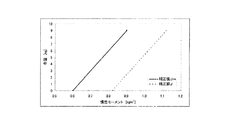
そこで、インバータ回路2の電源電圧を電源電圧検出部14によって検出し、検出した電源電圧を電源電圧補正演算部13に出力する。電源電圧補正演算部13は、入力された電源電圧と決定された電源電圧とを比較し、ROM19に記憶しておいたインバータ回路2の電源電圧と慣性モーメントJの補正量との関係を表すデータテーブル(図2参照)から補正量J1を読み出して決定する。例えば、図2に示すように、電源電圧が250〔V〕の場合は、補正量J1は0.10〔kgm2〕となり、電源電圧が280〔V〕の場合は、補正量J1は0〔kgm2〕となる。すなわち、インバータ回路2の電源電圧が上昇するにつれて補正量J1は徐々に減少する。
Therefore, the power supply voltage of the
次に、駆動モータ1の巻線抵抗のずれを補正する手順について説明する。駆動モータ1の巻線温度が変化すると、駆動モータ1の伝導率が変化し巻線抵抗Rが変化する。そのため、ベクトル演算で使用しているモータ動作状況によって決定された巻線抵抗値と異なってしまう。その結果、トルク電流が指令通りに流れず、出力トルクにもずれが生じる。
Next, the procedure for correcting the winding resistance deviation of the
そこで、駆動モータ1の巻線温度を巻線温度検出部16によって検出し、検出した巻線温度を巻線温度補正演算部15に出力する。巻線温度補正演算部15は、入力された巻線温度と決定された巻線温度とを比較し、ROM19に記憶しておいた駆動モータ1の巻線温度と慣性モーメントJの補正量との関係を表すデータテーブル(図3参照)から補正量J2を読み出して決定する。例えば、図3に示すように、巻線温度が10〔℃〕の場合は、補正量J2は0.05〔kgm2〕となり、巻線温度が20〔℃〕の場合は、補正量J2は0〔kgm2〕となる。すなわち、駆動モータ1の巻線温度が上昇するにつれて補正量J2は徐々に減少する。
Therefore, the winding temperature of the
以上より、補正量J1、J2が決定された後、慣性モーメントJの補正を行なう。 As described above, after the correction amounts J1 and J2 are determined, the inertia moment J is corrected.
Jm=J+J1+J2 (16)
このとき、慣性モーメントJに加算する補正量は、電源電圧補正量J1と巻線温度補正量J2のいずれか一つ、もしくは、複数を加算しても良い。
Jm = J + J1 + J2 (16)
At this time, the correction amount to be added to the moment of inertia J may be one of the power supply voltage correction amount J1 and the winding temperature correction amount J2, or a plurality of correction amounts.
この慣性モーメントJの補正により、容量判定部12は、演算された慣性モーメントJmに基づいてROM19に記憶しておいた慣性モーメントと収容物の容量との関係を表すデータテーブル(図4参照)から容器に収容された収容物の容量を決定することができる。
By correcting the inertia moment J, the
次に、図5に示すフローチャートに基づいて、容量判定手段を説明する。先ず、電気機器に対する入力操作によって、容量判定部12は容器に収容された収容物の容量判定が開始する。
Next, capacity determination means will be described based on the flowchart shown in FIG. First, the
モータ出力電圧演算部7は、演算するために任意に決定した加速トルク電流Iq(+)が入力され、入力された加速トルク電流Iq(+)に基づいて印加電圧信号を生成しインバータ回路2に出力する。インバータ回路2は、印加電圧信号に基づいた印加電圧を駆動モータ1に出力し、駆動モータ1の回転が加速する(S1)。
The motor output
回転数演算部6は、入力された加速トルク電流Iq(+)に基づいて回転する駆動モータ1の回転数ωが開始回転数ω1に達するかを検出する(S2)。回転数ωが開始回転数ω1に達したら、その開始回転数ω1をRAM18に保存し(S3)、保存と同時にタイマ7の測定を開始する(S4)。次に、回転数演算部6は、回転数ωが終了回転数ω2に達するかを検出する(S5)。回転数ωが終了回転数ω2に達したら、その終了回転数ω2をRAM18に保存し(S6)、保存と同時にタイマ7の測定を終了させ、その経過時間t1をRAM18に保存する(S6、S7、S8)。
The rotational
回転数演算部6が駆動モータ1の回転数ωが任意に決定した上限の回転数に達したことを検出したら(S9)、モータ出力電圧演算部7に演算するために任意に決定した減速トルク電流Iq(−)が入力される。モータ出力電圧演算部7は、入力された減速トルク電流Iq(−)に基づいて印加電圧信号を生成しインバータ回路2に出力する。インバータ回路2は、印加電圧信号に基づいた印加電圧を駆動モータ1に出力し、駆動モータ1の回転が減速する(S10)。
When the rotational
回転数演算部6は、入力された減速トルク電流Iq(−)に基づいて回転する駆動モータ1の回転数ωが開始回転数ω3に達するかを検出する(S11)。回転数ωが開始回転数ω3に達したら、その開始回転数ω3をRAM18に保存し(S12)、保存と同時にタイマ7の測定を開始する(S13)。次に、回転数演算部6は、回転数ωが終了回転数ω4に達するかを検出する(S14)。回転数ωが終了回転数ω4に達したら、その終了回転数ω4をRAM18に保存し(S15)、保存と同時にタイマ7の測定を終了させ、その経過時間t2をRAM18に保存する(S16、S17、S18)。
The rotational
回転数演算部6が駆動モータ1の回転数ωが任意に決定した下限の回転数に達したことを検出したら、RAM18に保存した開始回転数ω1、ω3と、終了回転数ω2、ω4と、経過時間t1、t2を慣性モーメント演算部11に出力する(S18)。
When the rotational
慣性モーメント演算部11は、回転数演算部6から入力された開始回転数ω1、ω3と終了回転数ω2、ω4と経過時間t1、t2と、任意に設定された加速トルク電流Iq(+)および減速トルク電流Iq(−)と、駆動モータ1の固有値である極対数Pおよび鎖交磁束数Φとから慣性モーメントJを演算する(S19)。
The inertia moment calculation unit 11 includes start rotation speeds ω1, ω3, end rotation speeds ω2, ω4, elapsed times t1, t2 input from the rotation
次に、インバータ電源電圧測定部14がインバータ回路の電源電圧を検出し、検出した電源電圧を電源電圧補正演算部13に出力する(S20)。電源電圧補正演算部13は、入力された電源電圧に基づいてROM19に記憶されるインバータ回路2の電源電圧と慣性モーメントJの補正量との関係を表すデータテーブルから補正量J1を決定する(S21)。巻線温度検出部16は、巻線の温度を検出し、巻線温度補正演算部15に出力する(S22)。巻線温度補正演算部15は、入力された巻線温度に基づいてROM19に記憶される駆動モータ1の巻線温度と慣性モーメントJの補正量との関係を表すデータテーブルから補正量J2を決定する(S23)。
Next, the inverter power supply
慣性モーメント演算部11で演算された慣性モーメントJに補正量J1と補正量J2を加算して補正された慣性モーメントJmを算出する(S24)。容量判定部12は、算出された慣性モーメントJmに基づいてROM19に記憶される慣性モーメントと収容物の容量との関係を表すデータテーブルから容器に収容された収容物の容量を判定する。
The corrected inertia moment Jm is calculated by adding the correction amount J1 and the correction amount J2 to the inertia moment J calculated by the inertia moment calculator 11 (S24). The
次に、本実施形態のモータ駆動装置を電気機器である洗濯機に適用する。洗濯機は、容器である洗濯槽に直接駆動モータ1を取り付けたダイレクトドライブ方式とされ、駆動モータ1の回転数が直接洗濯槽の回転数となる。洗濯機は、低速で洗濯槽を回転させて収容物である洗濯物の洗濯を行なう洗い運転やすすぎ運転と、高速で洗濯槽を回転させて脱水を行なう脱水運転と、洗濯槽に入っている容量、すなわち、洗濯物の布量の検知を行なう布量検知運転と、洗濯機自体の振動の検知を行なう振動検知運転とを行なう。
Next, the motor drive device of the present embodiment is applied to a washing machine that is an electrical device. The washing machine is a direct drive system in which the
洗濯機の操作パネルには、洗いスイッチ、すすぎスイッチ、脱水スイッチ、コーススイッチ、水量スイッチ等が設けられている。各スイッチを操作することにより、洗濯機のメインマイコンが、モータ駆動装置のマイコン3に指令を出して、それぞれの運転が行われる。なお、コーススイッチの操作により、洗い、すすぎ、脱水の一連の運転が自動的に行われる。水量スイッチの操作により、洗濯物の布量を検出して、布量に応じて給水量が決められ、給水が行われる。
On the operation panel of the washing machine, a washing switch, a rinsing switch, a dehydration switch, a course switch, a water amount switch, and the like are provided. By operating each switch, the main microcomputer of the washing machine issues a command to the
洗濯機の運転を行なうとき、洗い運転の前に、布量検知運転が行われる。メインマイコンが、洗いスイッチからの入力を受けると、メインマイコンからの指令により、マイコン3は、駆動モータ1を一定トルクで回転させるようにトルク制御を開始する。このときのメインマイコンから入力された指令トルクは、予め設定されており、マイコン3は、指令トルクに基づいて駆動モータ1を駆動する。そして、洗濯槽の回転数から布量が検出される。続いて、布量に応じた給水が行われ、洗い運転が開始される。
When the washing machine is operated, the cloth amount detection operation is performed before the washing operation. When the main microcomputer receives an input from the washing switch, the
これにより、洗濯機は、電流センサを使用せずに洗濯槽に収容された洗濯物の布量を検出することができる。また、駆動モータ1の回転数ωと指令トルク電流Iqによって演算した慣性モーメントJに、インバータ回路2の電源電圧から演算した補正量J1と駆動モータ1の巻線温度から演算した補正量J2よって洗濯槽の布量を判定するので、布量検知の精度が向上し、洗剤量を正確に決定できる。この結果、洗い性能の良い洗濯機を提供することができる。
Thereby, the washing machine can detect the amount of clothes of the laundry accommodated in the washing tub without using the current sensor. Further, the inertia moment J calculated from the rotational speed ω of the
[第2実施形態]
以下、本発明の第2実施形態について図6および図7に基づいて詳細に説明する。このモータ駆動装置が第1実施形態のモータ駆動装置と相違する点は、図6に示すように、駆動モータ1の巻線温度を検出していた巻線温度検出部16と、検出した巻線温度から慣性モーメントJの補正量J2を演算する巻線温度補正演算部15を持たず、モータケース1a内の温度を検出するモータケース温度検出手段であるモータケース温度検出部20と、検出されたモータケース1a内部の温度から慣性モーメントJの補正量J3を演算するモータケース温度補正演算部21を備えている点である。
[Second Embodiment]
Hereinafter, the second embodiment of the present invention will be described in detail with reference to FIGS. 6 and 7. The motor driving device is different from the motor driving device of the first embodiment in that the winding
すなわち、本実施形態では、駆動モータ1の巻線温度から慣性モーメントJの補正量J2を演算していたのを、モータケース1a内部の温度から慣性モーメントJの補正量J3を演算していることである。これにより、駆動モータ1の構造に関係なく温度を検出する検出部を設けることができる。
That is, in this embodiment, the correction amount J2 of the inertia moment J is calculated from the winding temperature of the
次に、モータケース温度検出部20とモータケース温度補正演算部21による慣性モーメントJの補正量J3の演算方法を説明する。なお、その他の演算部分は、第1実施形態と同様であるので、その説明は省略する。
Next, a calculation method of the correction amount J3 of the moment of inertia J by the motor case
先ず、駆動モータ1が内装されたモータケース1a内部の温度をモータケース温度検出部20によって検出し、検出した内部の温度をモータケース温度補正演算部21に出力する。モータケース温度補正演算部21は、入力された内部の温度と予め決定された内部の温度とを比較し、ROM19に記憶しておいたモータケース1a内部の温度と慣性モーメントJの補正量との関係を表すデータテーブル(図7参照)から補正量J3を読み出して決定する。
First, the temperature inside the
決定された補正量J3を第1実施形態と同様に、(16)式に代入して補正した慣性モーメントJmを算出し、容量を判定する。 Similar to the first embodiment, the corrected moment of inertia Jm is calculated by substituting the determined correction amount J3 into the equation (16) to determine the capacity.
[第3実施形態]
以下、本発明の第3実施形態について、図8〜図11に基づいて詳細に説明する。
[Third Embodiment]
Hereinafter, the third embodiment of the present invention will be described in detail with reference to FIGS.
モータ駆動装置の構成部品である駆動モータ1や容器等には、それぞれにおいて製造許容範囲が存在する。各部品は、その製造許容範囲内で製造されているため、各部品で製造許容範囲内のばらつきが生じる。そのような部品で構成されるモータ駆動装置が複数存在する場合、例えば、容器の収容物の容量や駆動する周辺環境等を一致させたとしても、各モータ駆動装置で異なる慣性モーメントが演算される。この結果、演算された慣性モーメントから容器の収容物の容量を判定する場合、各モータ駆動装置で異なった容量を判定してしまう問題がある。
Each of the
そこで、本実施形態では、基準とする慣性モーメントJ0を決め、この基準慣性モーメントJ0と使用するモータ駆動装置の慣性モーメントJとの差分からばらつき補正量J4を演算し、このばらつき補正量J4をモータ駆動装置の慣性モーメントJに加算することにより、いずれのモータ駆動装置であっても、製造許容範囲で存在するばらつきによって生じる装置間の慣性モーメントJの誤差を解消する。 Therefore, in this embodiment, a reference inertia moment J0 is determined, a variation correction amount J4 is calculated from the difference between this reference inertia moment J0 and the inertia moment J of the motor driving device to be used, and this variation correction amount J4 is calculated as the motor. By adding to the inertia moment J of the drive device, any motor drive device eliminates the error of the inertia moment J between the devices caused by variations existing in the manufacturing tolerance.
次に、本実施形態のモータ駆動装置の構造を説明する。本発明のモータ駆動装置は、図8に示すように、慣性モーメントJと基準慣性モーメントJ0とから慣性モーメント補正量であるばらつき補正量J4を演算するばらつき補正演算部22を備える。また、動作状況検出手段である動作手段は、ロータ位置検出部4と、モータ回転数演算部6と、慣性モーメント演算部11とから構成される。なお、その他の構成は、第1実施形態および第2実施形態のモータ駆動装置と同様の構成とされる。
Next, the structure of the motor drive device of this embodiment will be described. As shown in FIG. 8, the motor drive device of the present invention includes a variation
次に、ばらつき補正演算部22のばらつき補正量J4の演算方法を説明する。なお、その他の演算部分は、第1実施形態および第2実施形態と同様であるので、その説明は省略する。
Next, a method of calculating the variation correction amount J4 of the variation
規格値通りに製造されたモータ駆動装置を基準装置として、容器の慣性モーメントJ0を前述の(15)式より演算する。この演算結果をまとめると、図9に示すように、慣性モーメントJ0と容量とが比例した一次関数となる。 Using the motor drive device manufactured according to the standard value as a reference device, the moment of inertia J0 of the container is calculated from the aforementioned equation (15). When the calculation results are summarized, as shown in FIG. 9, a linear function in which the moment of inertia J0 and the capacity are proportional is obtained.
同じ規格で製造されたモータ駆動装置において、同様に容器の慣性モーメントJを前述の(15)式より演算する。この演算結果をまとめると、基準駆動モータ1sと同様に慣性モーメントJと容量とが比例した一次関数となる。 Similarly, in the motor drive device manufactured according to the same standard, the inertia moment J of the container is calculated from the above-described equation (15). Summarizing the calculation results, a linear function in which the moment of inertia J and the capacity are proportional to each other is obtained as in the case of the reference drive motor 1s.
しかし、図10に示すように、基準モータ駆動装置の慣性モーメントJ0と他のモータ駆動装置の慣性モーメントJは異なる。本来ならば、同じ構造、同じ部品で構成されているので、それぞれから演算された慣性モーメントは一致する。ところが、モータ駆動装置を構成する部品は、それぞれにおいて製造許容範囲内のばらつきを有している。そのため、製造許容範囲内で異なる部品で組み立てられたモータ駆動装置は、製品としての重量や摩擦力等が異なる。結果として、図10に示すように、基準モータ1駆動装置の慣性モーメントJ0と他のモータ駆動装置の慣性モーメントJとが異なる。
However, as shown in FIG. 10, the moment of inertia J0 of the reference motor driving device is different from the moment of inertia J of other motor driving devices. Originally, they are composed of the same structure and the same parts, so that the moments of inertia calculated from them match. However, the components constituting the motor drive device have variations within the manufacturing tolerance. For this reason, motor drive devices assembled with different parts within the manufacturing tolerance range differ in product weight, frictional force, and the like. As a result, as shown in FIG. 10, the moment of inertia J0 of the
しかしながら、慣性モーメントJと容量の関係は、モータ駆動装置が異なっても同じ傾きを持つ一次関数である。すなわち、基準モータ駆動装置の慣性モーメントJ0と他のモータ駆動装置の慣性モーメントJとの差は、常に一定となる。したがって、基準モータ駆動装置の慣性モーメントJ0と他のモータ駆動装置の慣性モーメントJとの差から慣性モーメントJのばらつき補正量J4を演算し、演算したばらつき補正量J4を測定した慣性モーメントJに加算する。これにより、図11に示すように、基準モータ駆動装置の慣性モーメントJ0と一致した正確な慣性モーメントJmを演算することができる。そこで、慣性モーメントJに加算するばらつき補正量J4は、
J4=J0−J (17)
となる。この(17)式より演算された補正量J4を第1実施形態および第2実施形態と同様に、(16)式に代入して補正した慣性モーメントJmを算出し、容量を判定する。これにより、異なるモータ駆動装置の慣性モーメントJが基準モータ駆動装置の慣性モーメントJ0と一致するので、正確な容量を判定することができる。
However, the relationship between the moment of inertia J and the capacity is a linear function having the same inclination even if the motor driving device is different. That is, the difference between the moment of inertia J0 of the reference motor driving device and the moment of inertia J of other motor driving devices is always constant. Therefore, the variation correction amount J4 of the inertia moment J is calculated from the difference between the inertia moment J0 of the reference motor driving device and the inertia moment J of the other motor driving device, and the calculated variation correction amount J4 is added to the measured inertia moment J. To do. As a result, as shown in FIG. 11, an accurate moment of inertia Jm that coincides with the moment of inertia J0 of the reference motor driving device can be calculated. Therefore, the variation correction amount J4 to be added to the moment of inertia J is
J4 = J0-J (17)
It becomes. Similar to the first and second embodiments, the correction amount J4 calculated from the equation (17) is substituted into the equation (16) to calculate the corrected inertia moment Jm, and the capacity is determined. Thereby, since the inertia moment J of a different motor drive device corresponds with the inertia moment J0 of a reference | standard motor drive device, an exact capacity | capacitance can be determined.
なお、このばらつき補正量J4は、製品を流通する前にあらかじめ演算しておき、モータ駆動装置に備えられたROM19に保存しておく。これにより、収容量を判定する際、ばらつき補正演算部21は、ROM19に記憶されたばらつき補正量J4を読み出し、演算した慣性モーメントJに加算することで補正した慣性モーメントJmを演算することができる。したがって、収容物を判定する度に、使用駆動モータ1cの慣性モーメントJを演算することがないため、演算処理による負荷を低減することができる。
The variation correction amount J4 is calculated in advance before the product is distributed, and is stored in the
また、ばらつき補正量J4を書き換え可能な不揮発性メモリに保存してもよい。これにより、使用による経時劣化等によってばらつき補正量J4を修正することができる。 The variation correction amount J4 may be stored in a rewritable nonvolatile memory. As a result, the variation correction amount J4 can be corrected due to deterioration over time due to use or the like.
ところで、このばらつき補正量J4の演算は、モータ駆動装置の生産工程における製品の組み立てが終わり、使用する部品が各製品で決定された後に行なう。これにより、利用者の手を煩わせることなく慣性モーメントJのばらつき補正量J4を演算することができる。また、ばらつき補正量J4を演算するまでの環境を同一の環境で行なえるため、製品ごとのばらつきを最も正しく補正することができる。 By the way, the calculation of the variation correction amount J4 is performed after the assembly of the product in the production process of the motor drive device is completed and the parts to be used are determined for each product. Thereby, the variation correction amount J4 of the moment of inertia J can be calculated without bothering the user. In addition, since the environment up to the calculation of the variation correction amount J4 can be performed in the same environment, the variation for each product can be corrected most accurately.
また、マイコン3は、ばらつき補正量が閾値を超えるか否かを検出する異常検出手段とを備える。この異常検出手段によって、モータ駆動装置が規格通りに製造されているかを検査することができる。
In addition, the
すなわち、各モータ駆動装置のばらつきは、各部品に存在する製造許容範囲によって生じるものである。そのため、製造許容範囲よりも大きなばらつきがある場合は、部品組み立ての異常、あるいは、モータ駆動装置内への異物混入等の不具合があると考えられる。そこで、本実施形態のモータ駆動装置は、あらかじめ製造許容範囲である閾値を設定し、演算されらばらつき補正量J4がその閾値を超えるか否かを検出する。これにより、マイコン3は、不具合があるか否かを判断することができる。
That is, the variation of each motor drive device is caused by the manufacturing tolerance that exists in each component. For this reason, if there is a variation larger than the allowable manufacturing range, it is considered that there is a problem such as an abnormality in parts assembly or a foreign matter mixed in the motor drive device. Therefore, the motor drive device of this embodiment sets a threshold value that is a manufacturing allowable range in advance, and detects whether or not the calculated variation correction amount J4 exceeds the threshold value. Thereby, the
また、使用による経時劣化等によってモータ駆動装置のばらつき補正量J4が変化する。この場合、あらかじめ基準慣性モーメントJ0をROM19あるいは不揮発性メモリに記憶させておく。
In addition, the variation correction amount J4 of the motor drive device changes due to deterioration with use or the like. In this case, the reference moment of inertia J0 is stored in advance in the
先ず、ばらつき補正量J4の補正モードを実行する。補正モードでは、上記と同様の動作を実行し、慣性モーメントJを演算する。演算した慣性モーメントと記憶された基準慣性モーメントJ0からばらつき補正量を演算する。演算したばらつき補正量J4は、ROM19あるいは不揮発性メモリに記憶され、その値が更新される。これにより、現状に対して常に的確な補正量を加算することができるので、正確な容器の収容物の容量を演算することができる。
First, the correction mode for the variation correction amount J4 is executed. In the correction mode, the same operation as described above is executed to calculate the moment of inertia J. A variation correction amount is calculated from the calculated inertia moment and the stored reference inertia moment J0. The calculated variation correction amount J4 is stored in the
なお、本発明は、上記実施形態に限定されるものではなく、本発明の範囲内で上記実施形態に多くの修正および変更を加え得ることは勿論である。 In addition, this invention is not limited to the said embodiment, Of course, many corrections and changes can be added to the said embodiment within the scope of the present invention.
例えば、本発明のモータ駆動装置を洗濯機に適用するだけでなく、洗濯乾燥機や電子レンジといった、収容された収容物の容量を検出し、その検出結果に基づいて運転方法を変更してモータ駆動する電気機器に適用することが可能である。なお、電子レンジの場合の容器とは、収容物を載置する載置皿である。 For example, not only the motor driving device of the present invention is applied to a washing machine, but also the capacity of a contained item such as a washing / drying machine or a microwave oven is detected, and the operation method is changed based on the detection result to change the motor It can be applied to an electric device to be driven. In addition, the container in the case of a microwave oven is a mounting tray which mounts a stored item.
また、本実施形態において駆動モータによる容器の駆動方式はダイレクトドライブ方式を採用しているが、特にこの限りではなく、例えば、傘歯車やベルト等の連結装置を用いて容器を回転させるものであっても良い。 Further, in this embodiment, the drive system of the container by the drive motor adopts the direct drive system. However, this is not particularly limited, and for example, the container is rotated using a connecting device such as a bevel gear or a belt. May be.
また、本発明は、演算された慣性モーメントに加算する補正量が、電源電圧と巻線温度から求めた補正量、電源電圧とモータケース温度から求めた補正量、あるいは、基準慣性モーメントとの差から求めたばらつき補正量を加えて補正しているが、特にこの限りではない。例えば、ばらつき補正量によって補正された慣性モーメントに、電源電圧から求めた補正量を加算して慣性モーメントを補正するように、求めた補正量のうちいずれか1つ、あるいは、複数を加えて慣性モーメントを補正してもよい。 Further, according to the present invention, the correction amount to be added to the calculated moment of inertia is the difference between the correction amount obtained from the power supply voltage and the winding temperature, the correction amount obtained from the power supply voltage and the motor case temperature, or the reference inertia moment. Although the correction is performed by adding the variation correction amount obtained from the above, this is not particularly limited. For example, in order to correct the moment of inertia by adding the correction amount obtained from the power supply voltage to the inertia moment corrected by the variation correction amount, the inertia is obtained by adding one or more of the obtained correction amounts. The moment may be corrected.
1 駆動モータ
1a モータケース
2 インバータ回路
3 マイコン
4 ロータ位置検出部
5 回転角度演算部
6 モータ回転数演算部
7 モータ出力電圧演算部
12 容量判定部
13 電源電圧補正演算部
14 電源電圧検出部
15 巻線温度補正演算部
16 巻線温度検出部
17 タイマ
18 RAM
19 ROM
20 モータケース温度検出部
21 モータケース温度補正演算部
22 ばらつき補正演算部
DESCRIPTION OF
19 ROM
20 Motor
Claims (5)
前記制御装置は、前記駆動モータの動作状況に基づいて、前記駆動モータの回転数から演算された前記容器の慣性モーメントを補正する慣性モーメント補正手段を備え、前記慣性モーメント補正手段は、基準となる駆動モータを動作させたときに得られる慣性モーメントを基準値とし、駆動モータを動作させたときの慣性モーメントと基準値とから演算されるばらつき補正量に基づいて慣性モーメントを補正することを特徴とするモータ駆動装置。 An inverter circuit that outputs an applied voltage to a drive motor for rotating a container that accommodates the contents; a control device that controls the inverter circuit; and an operation state detection unit that detects an operation state of the drive motor,
The control device includes an inertia moment correction unit that corrects the inertia moment of the container calculated from the rotational speed of the drive motor based on an operation state of the drive motor , and the inertia moment correction unit serves as a reference. The moment of inertia obtained when the drive motor is operated is set as a reference value, and the moment of inertia is corrected based on a variation correction amount calculated from the moment of inertia when the drive motor is operated and the reference value. A motor drive device.
前記制御装置は、前記駆動モータの回転数から前記容器の慣性モーメントを演算する慣性モーメント演算手段と、検出された前記駆動モータの動作状況に基づいて 前記慣性モーメントを補正する慣性モーメント補正手段と、前記補正された慣性モーメントから前記容器に収容された収容物の容量を判定する判定手段とを備え、
前記慣性モーメント補正手段は、基準となる駆動モータを動作させたときに得られる慣性モーメントを基準値とし、駆動モータを動作させたときの慣性モーメントと基準値とから演算されるばらつき補正量に基づいて慣性モーメントを補正することを特徴とするモータ駆動装置。 An inverter circuit that outputs an applied voltage to a drive motor for rotating a container that accommodates the contents; a control device that controls the inverter circuit; and an operation state detection unit that detects an operation state of the drive motor,
The control device includes an inertia moment calculating means for calculating an inertia moment of the container from the rotational speed of the drive motor, an inertia moment correcting means for correcting the inertia moment based on the detected operation state of the drive motor, Determination means for determining the capacity of the container accommodated in the container from the corrected moment of inertia,
The inertia moment correction means uses the inertia moment obtained when the reference drive motor is operated as a reference value, and is based on a variation correction amount calculated from the inertia moment when the drive motor is operated and the reference value. And a motor drive device for correcting the moment of inertia .
慣性モーメント補正手段は、前記電源電圧から慣性モーメントの補正量を演算することを特徴とする請求項1または2に記載のモータ駆動装置。 The operating state detection means includes power supply voltage detection means for detecting the power supply voltage of the inverter circuit,
The motor driving apparatus according to claim 1, wherein the inertia moment correction unit calculates a correction amount of the inertia moment from the power supply voltage.
慣性モーメント補正手段は、前記巻線温度またはモータケースの温度から慣性モーメントの補正量を演算することを特徴とする請求項2または3に記載のモータ駆動装置。 The operating state detecting means includes temperature detecting means for detecting the winding temperature of the drive motor or the temperature of the motor case,
4. The motor driving apparatus according to claim 2, wherein the inertia moment correction means calculates a correction amount of the inertia moment from the winding temperature or the temperature of the motor case.
Priority Applications (1)
| Application Number | Priority Date | Filing Date | Title |
|---|---|---|---|
| JP2006055227A JP4777093B2 (en) | 2006-03-01 | 2006-03-01 | Motor drive device and electric apparatus using the same |
Applications Claiming Priority (1)
| Application Number | Priority Date | Filing Date | Title |
|---|---|---|---|
| JP2006055227A JP4777093B2 (en) | 2006-03-01 | 2006-03-01 | Motor drive device and electric apparatus using the same |
Publications (3)
| Publication Number | Publication Date |
|---|---|
| JP2007229256A JP2007229256A (en) | 2007-09-13 |
| JP2007229256A5 JP2007229256A5 (en) | 2008-09-18 |
| JP4777093B2 true JP4777093B2 (en) | 2011-09-21 |
Family
ID=38550445
Family Applications (1)
| Application Number | Title | Priority Date | Filing Date |
|---|---|---|---|
| JP2006055227A Active JP4777093B2 (en) | 2006-03-01 | 2006-03-01 | Motor drive device and electric apparatus using the same |
Country Status (1)
| Country | Link |
|---|---|
| JP (1) | JP4777093B2 (en) |
Families Citing this family (7)
| Publication number | Priority date | Publication date | Assignee | Title |
|---|---|---|---|---|
| JP4666662B2 (en) * | 2007-10-19 | 2011-04-06 | パナソニック株式会社 | Washing machine |
| JP2009240548A (en) * | 2008-03-31 | 2009-10-22 | Panasonic Corp | Washing machine |
| JP5104670B2 (en) * | 2008-09-02 | 2012-12-19 | パナソニック株式会社 | Washing machine |
| JP5104672B2 (en) * | 2008-09-02 | 2012-12-19 | パナソニック株式会社 | Washing machine |
| JP5104671B2 (en) * | 2008-09-02 | 2012-12-19 | パナソニック株式会社 | Washing machine |
| JP5104669B2 (en) * | 2008-09-02 | 2012-12-19 | パナソニック株式会社 | Washing machine |
| JP7463635B2 (en) * | 2016-09-30 | 2024-04-09 | ニデックパワートレインシステムズ株式会社 | Control device, control method, motor, and electric oil pump |
Family Cites Families (3)
| Publication number | Priority date | Publication date | Assignee | Title |
|---|---|---|---|---|
| JP2003210888A (en) * | 2002-01-25 | 2003-07-29 | Sharp Corp | Method for detecting amount of cloths in washing machine, device for detecting amount of cloths in washing, and washing machine |
| JP4007161B2 (en) * | 2002-11-01 | 2007-11-14 | 松下電器産業株式会社 | Washing and drying machine |
| JP3977762B2 (en) * | 2003-03-06 | 2007-09-19 | 株式会社東芝 | Drum washing machine |
-
2006
- 2006-03-01 JP JP2006055227A patent/JP4777093B2/en active Active
Also Published As
| Publication number | Publication date |
|---|---|
| JP2007229256A (en) | 2007-09-13 |
Similar Documents
| Publication | Publication Date | Title |
|---|---|---|
| JP4777093B2 (en) | Motor drive device and electric apparatus using the same | |
| US9983253B2 (en) | Method and apparatus for identifying the winding short of bar wound electric machine at standstill condition | |
| US6163912A (en) | Washing machine | |
| CN100417004C (en) | Motor controlling equipment and washer and dryer using the same | |
| JP3962668B2 (en) | Drum washing machine | |
| EP2397600B1 (en) | Method for measuring the moment of inertia of a drum of a washing machine and washing machine arranged to implement said method | |
| US8324847B2 (en) | Motor for washer, method for controlling the motor, and method for controlling the washer | |
| CN104631052A (en) | Motor driving apparatus and laundry treatment machine including the same | |
| JP4527596B2 (en) | MOTOR CONTROL DEVICE AND ELECTRIC DEVICE USING THE SAME | |
| JP4242263B2 (en) | Washing machine | |
| JPH11319367A (en) | Washing machine | |
| JP7518818B2 (en) | Method, control device and inverter for determining a correction value representative of the angular difference between the estimated position and the actual position of the d-axis - Patents.com | |
| JP4666662B2 (en) | Washing machine | |
| CN101005262A (en) | Ac generator sensor-less vector control method and control device thereof | |
| JP2010154588A (en) | Motor controller with magnetic flux angle correcting function | |
| JP2008154314A (en) | Motor driving apparatus and washing machine equipped with same | |
| JP4584723B2 (en) | Motor drive device for washing machine | |
| JP2010187537A (en) | Motor drive unit | |
| EP3701076B1 (en) | Washing machine and control method of the same | |
| KR102471917B1 (en) | A control method of the laundry apparatus | |
| JP2020054785A (en) | Washing machine | |
| JP4679629B2 (en) | Washing machine | |
| US20220372687A1 (en) | Washer and control method thereof | |
| JP2021044938A (en) | Motor control device and control method thereof | |
| JP4196660B2 (en) | Electric motor control device |
Legal Events
| Date | Code | Title | Description |
|---|---|---|---|
| A521 | Written amendment |
Free format text: JAPANESE INTERMEDIATE CODE: A523 Effective date: 20080804 |
|
| A621 | Written request for application examination |
Free format text: JAPANESE INTERMEDIATE CODE: A621 Effective date: 20080804 |
|
| A977 | Report on retrieval |
Free format text: JAPANESE INTERMEDIATE CODE: A971007 Effective date: 20100913 |
|
| A131 | Notification of reasons for refusal |
Free format text: JAPANESE INTERMEDIATE CODE: A131 Effective date: 20100921 |
|
| A521 | Written amendment |
Free format text: JAPANESE INTERMEDIATE CODE: A523 Effective date: 20101116 |
|
| TRDD | Decision of grant or rejection written | ||
| A01 | Written decision to grant a patent or to grant a registration (utility model) |
Free format text: JAPANESE INTERMEDIATE CODE: A01 Effective date: 20110607 |
|
| A01 | Written decision to grant a patent or to grant a registration (utility model) |
Free format text: JAPANESE INTERMEDIATE CODE: A01 |
|
| A61 | First payment of annual fees (during grant procedure) |
Free format text: JAPANESE INTERMEDIATE CODE: A61 Effective date: 20110629 |
|
| R150 | Certificate of patent or registration of utility model |
Ref document number: 4777093 Country of ref document: JP Free format text: JAPANESE INTERMEDIATE CODE: R150 Free format text: JAPANESE INTERMEDIATE CODE: R150 |
|
| FPAY | Renewal fee payment (event date is renewal date of database) |
Free format text: PAYMENT UNTIL: 20140708 Year of fee payment: 3 |