JP4776646B2 - Image processing apparatus, image processing method, program, and recording medium - Google Patents
Image processing apparatus, image processing method, program, and recording medium Download PDFInfo
- Publication number
- JP4776646B2 JP4776646B2 JP2008059274A JP2008059274A JP4776646B2 JP 4776646 B2 JP4776646 B2 JP 4776646B2 JP 2008059274 A JP2008059274 A JP 2008059274A JP 2008059274 A JP2008059274 A JP 2008059274A JP 4776646 B2 JP4776646 B2 JP 4776646B2
- Authority
- JP
- Japan
- Prior art keywords
- color
- colorant
- image
- usage amount
- data
- Prior art date
- Legal status (The legal status is an assumption and is not a legal conclusion. Google has not performed a legal analysis and makes no representation as to the accuracy of the status listed.)
- Expired - Fee Related
Links
Images


Classifications
-
- H—ELECTRICITY
- H04—ELECTRIC COMMUNICATION TECHNIQUE
- H04N—PICTORIAL COMMUNICATION, e.g. TELEVISION
- H04N1/00—Scanning, transmission or reproduction of documents or the like, e.g. facsimile transmission; Details thereof
- H04N1/46—Colour picture communication systems
- H04N1/56—Processing of colour picture signals
- H04N1/60—Colour correction or control
- H04N1/6016—Conversion to subtractive colour signals
- H04N1/6019—Conversion to subtractive colour signals using look-up tables
Description
本発明は、画像形成に関し、より詳細には、色域を縮小して画像形成する、画像処理装置、画像処理方法、プログラム、およびに記録媒体に関する。 The present invention relates to image formation, and more particularly to an image processing apparatus, an image processing method, a program, and a recording medium that form an image with a reduced color gamut.
電子写真複写機、プリンタなどは、近年、パーソナルコンピュータなどの普及に伴い、1つのオフィスに複数台設置されるのが通常になってきている。このような理由から、画像処理装置をオフィスに展開する場合、画質に加え、画像形成のコストも重要視される方向にあるということができる。 In recent years, with the spread of personal computers and the like, a plurality of electrophotographic copying machines, printers, and the like are usually installed in one office. For this reason, when the image processing apparatus is deployed in an office, it can be said that in addition to the image quality, the cost of image formation is in the direction of importance.
画像形成を行う場合、モノクロ印刷とカラー印刷とが可能であり、モノクロ印刷の場合、レーザ走査方式であろうとインクジェット方式であろうと、基本的に使用する色剤は、K(黒)1色である。一方、カラー印刷の場合、通常では、色剤の黒再現性を向上させ、また他の色材量を低減させるため、C(シアン)、M(マゼンタ)、Y(イエロー)、K(ブラック)の4色で色再現が行われる。また、ユーザの要求に応じて、場合によっては、CMYK以外の特殊なカラーを含めて4色以上の色剤が使用される。 When image formation is performed, monochrome printing and color printing are possible. In monochrome printing, whether the laser scanning method or the inkjet method is used, the colorant used is basically one color of K (black). is there. On the other hand, in the case of color printing, C (cyan), M (magenta), Y (yellow), and K (black) are usually used to improve the black reproducibility of the colorant and reduce the amount of other color materials. Color reproduction is performed with these four colors. Further, depending on the user's request, in some cases, four or more colorants including special colors other than CMYK are used.
画像をカラー表現する場合、各色は、単独で使用されるだけでなく、同一箇所で色剤を重ね合わせ、色混合を使用して様々な色相、明度などを表現することが必要である。このため、カラー画像の印刷に要するコストは、モノクロ印刷に比較して数倍に跳ね上がる場合もある。 When expressing an image in color, each color is not only used alone, but it is necessary to superimpose colorants at the same location and express various hues, brightness, etc. using color mixing. For this reason, the cost required for printing a color image may jump several times as compared with monochrome printing.
カラー画像形成を行う場合の上述したコスト増に対し、コストを抑制する目的から種々の検討が行われている。カラー画像形成のためのコスト削減は、通常、色剤の使用量を減らす、エコノモード、省インクモードなどとして参照されることもある「色剤使用量低減モード」を、画像処理装置に搭載することにより対応されている。 Various studies have been made for the purpose of suppressing the cost against the above-described increase in cost when color image formation is performed. Cost reduction for color image formation is usually implemented in the image processing device with a “coloring agent usage reduction mode” that is sometimes referred to as an econo mode, an ink saving mode, etc. It is supported by.
例えば、特開2006−270927号公報(特許文献1)では、印刷データから特定のパターンで間引き処理し、実際に使用される色剤量を低減する方法が開示されている。また、特開平09−216419号公報(特許文献2)では、入力データに対して一定の比率で階調を減らすことで、色剤使用量の大きいシャドウ側の成分を減らし、色材量を低減する方法が提案されている。特開2004−80266号公報(特許文献3)では、CMM(Color Matching Method:カラーマッチング色変換処理)を利用して、より細かな調整を可能とする方法も提案されている。 For example, Japanese Patent Laying-Open No. 2006-270927 (Patent Document 1) discloses a method of reducing the amount of colorant actually used by thinning out print data with a specific pattern. In Japanese Patent Laid-Open No. 09-216419 (Patent Document 2), by reducing the gradation at a constant ratio with respect to input data, the shadow side component with a large amount of colorant used is reduced, and the amount of color material is reduced. A method has been proposed. Japanese Patent Laid-Open No. 2004-80266 (Patent Document 3) also proposes a method that enables finer adjustment using CMM (Color Matching Method).
また、CMMを使用して色剤使用量を削減する方法は、特開2006−68982号公報(特許文献4)、国際出願WOA2003−043306号パンフレット(特許文献5)、特開2007−235661号公報(特許文献6)、特開2004−80266号公報(特許文献7)にも開示されている。 Also, methods for reducing the amount of colorant used using CMM are disclosed in Japanese Patent Application Laid-Open No. 2006-68982 (Patent Document 4), International Application WOA 2003-043306 Pamphlet (Patent Document 5), and Japanese Patent Application Laid-Open No. 2007-235661. (Patent Document 6) and Japanese Patent Application Laid-Open No. 2004-80266 (Patent Document 7).
特許文献4、特許文献6、特許文献7は、CMMを使用して色剤使用量を低減する点を開示し、特許文献5では、CMMを使用してハイライト・シャドーに関連して明度のことなる色剤について、異なる階調処理を行う点については開示する。しかしながら、特許文献4〜特許文献7は、いずれも色剤使用量を低減させることは、画像形成により再現される色域が削減されてしまうこと、および当該色域の削減による色再現性の劣化を最小にすることを課題とするものではない。
すなわち、特許文献1〜特許文献7に記載された画像形成技術は、あくまでも色材を低減するという処理そのものを解決課題とするか、またシャドー・ハイライトの色再現性をCMMを使用して向上させるものであり、カラー画像を色剤を削減しながら高精細に再現するため、実際にどの程度まで色剤を低減すべきか、また、その際の画質劣化をいかにして最小化させるかという技術について、解決課題とするものではない。具体的には、コストを重視するあまりに色剤を低減しすぎると、画像全体が薄くぼやけた画質となり、本来カラー化によって得られるはずであった画像の印象や心理的効果が損なわれ、結局の所、ユーザが画質およびコストを両方考慮した場合に満足することができる画像を形成することはできないのである。
In other words, the image forming techniques described in
本発明は、上述した従来技術の問題点に鑑み、色剤量の減少に伴う色域の減少が、画像に与える心理物理的影響を最小限としつつ、色剤量の削減を可能とする画像処理装置、画像処理方法、プログラムおよび記録媒体を提供することを目的とする。
本発明では、低減すべき色剤量の基準として、モノクロ印刷時の色剤使用量、すなわちモノクロ印刷時の色剤コストをできるだけ再現するように、色剤使用量削減モードを実装する。カラー画像形成時のトータルコストが、モノクロ印刷時のコストと同等となれば、モノクロ印刷からカラー印刷に切り換えた場合でも、ユーザが負担すべき消耗品(色剤)費用は、ユーザの希望により調節可能となり、コストおよび画質の両面でユーザのカラー画像形成要求に応えることが可能となる。 In the present invention, as a reference for the amount of colorant to be reduced, the colorant usage reduction mode is implemented so as to reproduce as much as possible the colorant usage during monochrome printing, that is, the colorant cost during monochrome printing. If the total cost for color image formation is equivalent to the cost for monochrome printing, even if switching from monochrome printing to color printing, the cost of consumables (colorants) to be borne by the user is adjusted according to the user's wishes. Therefore, it is possible to meet the user's color image formation request in both cost and image quality.
また、モノクロ印刷の画質は、階調特性のみで全情報が表現されているので、モノクロ印刷時の色剤量を基準として使用することで、各色相における階調バランスについても、そのために別のカラーマッチング処理を導入することなく最適に保つことができ、画像ドットの単純な間引き処理や、階調シフト演算による一律な階調ダウン処理よりも高品質な画像形成が実現可能となる。 In addition, the image quality of monochrome printing expresses all information with only the gradation characteristics. Therefore, using the amount of colorant at the time of monochrome printing as a reference, the gradation balance in each hue is also different. Optimum can be maintained without introducing color matching processing, and higher quality image formation can be realized than simple thinning processing of image dots or uniform gradation down processing by gradation shift calculation.
一方、本発明では、モノクロ印刷で色剤使用量が少ない高明度色、例えばYなどについては、色剤量を削減することにより、モノクロ印刷の色剤使用量に全色を統一すると、高明度色では視認性が悪くなり、カラー画像がユーザに対して与える心理的効果を損なうことになる。そこで、本発明では、色剤使用量と色相に関連して色剤使用量を制御するためのしきい値を採用する。しきい値よりも色剤使用量が少ない色相については、モノクロ印刷の色剤使用量よりも色剤使用量を増加させて視認性を確保する。 On the other hand, in the present invention, for high-lightness colors with a small amount of colorant used in monochrome printing, such as Y, if all colors are unified with the amount of colorant used for monochrome printing by reducing the amount of colorant, high brightness Visibility deteriorates in color, and the psychological effect that the color image gives to the user is impaired. Therefore, the present invention employs a threshold value for controlling the colorant usage amount in relation to the colorant usage amount and the hue. For hues that use less colorant than the threshold, visibility is ensured by increasing the colorant usage over monochrome printing.
色剤削減量の基準値としては、RGBデータを、例えばNTSC変換することにより与えられるモノクロ印刷時の色剤使用量が使用され、対応する画像データの印刷により、モノクロ印刷時に使用される色剤量の総量に可能な限り近くなるように、色剤使用量を制御する。 As the reference value of the color material reduction amount, the color material usage amount in monochrome printing given by, for example, NTSC conversion of RGB data is used, and the color material used in monochrome printing by printing corresponding image data The colorant usage is controlled to be as close as possible to the total amount.
このため、本発明では、ユーザに対し、出力画像が与える心理的効果の大きな色相領域、具体的にはハイライト色から中間色までについては、色剤使用量を基準値よりも増加させ、中間色からシャドウ色までは、基準値よりも減少させることで、全色剤使用量を、可能な限り基準値が与える全色剤量に近づくように設定する。 For this reason, in the present invention, for the hue area having a large psychological effect given to the output image to the user, specifically, from the highlight color to the intermediate color, the colorant usage amount is increased from the reference value, By reducing the shadow color from the reference value, the total colorant usage is set as close as possible to the total colorant given by the reference value.
また、本発明では、色剤使用量の特性曲線を切換えるためのしきい値を挟んだ両側で階調飛びなどの画像欠陥を生じさせないように、しきい値を挟んだ色剤使用量の特性曲線がなめらかに連続するように、しきい値よりもシャドウ色側で色剤使用量を提供するために、補正関数を使用して色剤使用量を計算し、色剤削減用データ構造に登録し、色変換処理のために使用する。 Further, in the present invention, the characteristics of the colorant usage amount with the threshold value interposed therebetween so as not to cause image defects such as gradation skipping on both sides of the threshold value for switching the characteristic curve of the colorant usage amount. In order to provide the colorant usage on the shadow color side of the threshold so that the curve is smoothly continuous, the colorant usage is calculated using the correction function and registered in the data reduction data structure. And used for color conversion processing.
さらに、本発明では、中間調画像と、文字・線オブジェクトとに対して異なる色剤削減量とすることで、カラー画像がユーザに与える心理的効果を最小化させながら、色剤量を削減し、低コスト化を可能とする。 Furthermore, the present invention reduces the amount of colorant while minimizing the psychological effect that the color image has on the user by using different amounts of colorant reduction for halftone images and character / line objects. , Enabling cost reduction.
以下、本発明を実施形態をもって説明するが、本発明は、後述する実施形態に限定されるものではない。 Hereinafter, although this invention is demonstrated with embodiment, this invention is not limited to embodiment mentioned later.
<セクションI:画像処理装置のハードウェア構成>
図1は、画像処理装置100の実施形態の機能ブロック図である。画像処理装置100は、制御部110と、制御部によりその動作が制御される画像形成部140とを含んで構成されている。制御部110は、中央処理装置(CPU)112と、ROM114と、RAM116と、NVRAM118とを含んでいる。CPU112は、画像処理装置100全体の処理を管理する。また、ROM114は、CPU112が実行するアプリケーションプログラムやデータを格納している。RAM116は、CPU112のプログラム実行のための実行空間を提供する。また、RAM116は、画像データを処理するための画像RAM116として実装することができる。NVRAM118は、RAM116に格納されたデータなどの一時退避させたり、また長期間にわたり保持するべき、データなどを格納している。
<Section I: Hardware Configuration of Image Processing Device>
FIG. 1 is a functional block diagram of an embodiment of the
画像処理装置100は、操作入力部126からのユーザ入力を受取り、ユーザI/F120に送付する。ユーザ入力を受領したユーザI/F120は、CPU112に対してユーザ指令を実行するためのコマンドなどを発行する。さらに画像処理装置100は、画像処理を専用に実行するためのASIC(Application Specific Integrated Circuit)122を含んでいる。ASIC122は、スキャナアプリケーションなどのアプリケーション手段から取得した画像データに対して各種画像処理を施して、プリント出力可能な出力データを生成する。なお、ASIC122は、本実施形態では、色変換手段およびPostScript(登録商標)などのPDL(Page Description Language)などのフォーマットとして出力データを生成する出力データ生成手段の機能を併せて実装する。
The
制御部110は、外部I/F130を含んでおり、外部I/F130を介して、外部接続されたパーソナルコンピュータなどの情報処理装置から、画像データを受領し、受領した画像データに対してASIC122による画像処理を施してプリント出力可能な出力データを生成する。外部I/F130としては、特に限定はされないが、Ethernet(登録商標)、USB(Universal Serial Buss)、IEEE1294、IEEE802.X、公衆電話網、ISDNなどのデータコネクションが可能なインタフェースを挙げることができる。
The
なお、画像処理装置100がスタンドアロンで各種アプリケーション処理が可能な実施形態では、外部I/F130は、公衆電話網、ISDNなどに接続されるモデム、TA/DSUなどとして実装することもできる。画像処理装置130は、ファクシミリの圧縮データを受領して、画像処理後、出力データを生成させることもできる。制御部110は、さらに入出力I/O124を備えている。入出力I/O124は、各種センサ128または後述するロータリエンコーダなどの出力信号を受領して、画像処理装置100の制御にフィードバックする。
In the embodiment in which the
画像形成部140は、制御部110の出力データをプリント出力するべく、制御部110から出力データおよび制御データを受け取り、各種ハードウェアを動作させて印刷物を出力する。画像形成部140は、インクジェットプリンタ、電子写真プリンタなど、これまで知られた画像形成プロセスを使用する画像形成エンジン148を含んでいる。
The
さらに、画像形成部130は、印刷制御部142と、駆動系制御部144と、高電圧制御部146とを含んでいる。画像形成部140が電子写真方式を使用する場合、印刷制御部142は、出力データを受け取り、出力データが含む画素ビットに対応して半導体レーザおよびボリゴンミラーなどの制御を行う。また、画像形成部140がインクジェット方式の画像形成エンジン148を実装する場合、印刷制御部142は、出力データに対応したインクジェットノズルの駆動パルスを生成し、ノズルを駆動する。
Further, the
駆動系制御部144は、画像形成エンジン148の画像形成処理に対応して印刷用紙などを搬送する搬送モータ、クラッチ、または分離爪などの駆動を管理する。駆動制御部144は、主走査モータ150および副走査モータ156の駆動パルスを生成し、ノズルヘッドを主走査方向へと移動させ、搬送モータを駆動して、印刷用紙を画像形成部140に供給する。印刷後の印刷用紙は、副走査モータ158の駆動により、画像形成部140の外部に排出され、印刷物としてユーザに提供される。各エンコーダ152、154は、主走査モータ150および副走査モータ156の回転数を検出し、出力を入出力I/O124に送付する。
The drive
なお、画像処理装置100が、電子写真方式を使用して画像形成を行う場合、高電圧制御部146が生成したバイアス電位は、帯電ローラ、転写ローラ、搬送ベルトなどに印加され、潜像形成および転写などのプロセスを可能とする。また、画像処理装置100が、インクジェットプリンタとして構成される場合、受像紙を搬送するための搬送ベルトに静電荷をチャージするため、高電圧が供給される。
When the
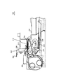
図2は、画像処理装置100を、インクジェットプリンタとして実装する場合の実施形態を示す。画像処理装置200は、ガイドロッド202と、ガイドレール204とによりキャリッジ206を主走査方向に摺動自在に保持する。ガイドロッド202とガイドレール204とは、ガイド部材として機能する。キャリッジ206は、主走査モータ208の回転が複数の駆動プーリにより構成される駆動部材214へと伝達され、主走査方向(図2の紙面上下方向に相当する。)に移動する。
FIG. 2 shows an embodiment in which the
このキャリッジ206は、例えば、イエロー(Y)、シアン(C)、マゼンタ(M)、ブラック(K)のインク滴を吐出する4個の吐出ヘッド212を含んで構成されている。吐出ヘッド212は、複数のインク吐出口が主走査方向と交叉する方向に配列されて構成され、そのインク滴吐出方向が下方に向くようにして配設されている。
The
吐出ヘッド212は、これまで知られたいかなる構成でも採用することができる。例えば、吐出ヘッド212は、圧電素子などの圧電アクチュエータ、発熱抵抗体などの電気熱変換素子を用いて液体の膜沸騰による相変化を利用するサーマルアクチュエータ、温度変化による金属相変化を用いる形状記憶合金アクチュエータ、静電荷を用いる静電アクチュエータなどを、液滴を吐出するための圧力発生手段として備えることができる。また、吐出ヘッド212は、各色毎に独立したヘッド構成に限るものではなく、複数の色の液滴を吐出する複数のノズルが一体化された構成とすることもできる。
The
キャリッジ206は、吐出ヘッド212に各色のインクを供給するための各色のサブタンク214を搭載している。サブタンク214は、色剤を溶解または分散させたインクを収容していて、吐出ヘッド212を介して上質紙や専用紙などの受像紙228に対するインクの吐出を可能としている。
The
受像紙228は、給紙カセット218に載置され、給紙ローラ220および分離パッド222などを含む給紙部から、吐出ヘッド212へと搬送される。受像紙228は、搬送ベルト224に静電吸着された後、吐出ヘッド212へと搬送され、さらに、吐出ヘッド212からの色剤により画像が形成された後、排出トレイ226上に排出される。
The
図3は、画像処理装置200を、主走査方向を紙面左右方向として配置し、平面構成を示した図である。画像処理装置200は、キャリッジ206を紙面上の矢線方向の主走査方向に往復移動させながら、画像信号に応じて吐出ヘッド212を駆動する。画像形成プロセスは、キャリッジ206の往復運動の間、受像紙228を静止させ、受像紙228に対してインクヘッド212からインク液滴を吐出して1行分を記録し、受像紙228を所定量搬送後、次の行の記録を行なう。なお、図3中、4色に対応するノズルを、212a−212dで示す。画像処理装置200は、印刷制御部142から送付される記録終了信号または受像紙228の後端が記録領域に到達した信号を検出して、記録動作を終了させ、受像紙228を排紙トレイ226上に排紙する。
FIG. 3 is a diagram showing a planar configuration in which the
画像処理装置200は、両面印刷処理機能を含むこともできる。両面印刷の場合には、表面(最初に印刷する面)の記録が終了したときに、駆動系制御部144を制御し、副走査方向を反転するように搬送部材を逆回転させ、鏡面給紙ユニット内に受像紙を送り、両面給紙ユニット内で受像紙228を反転させる。その後、駆動系制御部144の搬送方向を順方向に切換えて再度受像紙228を吐出ヘッド212に送った後、吐出ヘッド212に駆動信号を供給して画像形成を行うことにより実行される。
The
また、印字(記録)待機中、画像処理装置200は、キャリッジ206を、維持回復機構230側に移動し、キャップ232で吐出ヘッド212のノズル面をキャッピングすることによりノズルを湿潤状態に保ち、インク乾燥による吐出不良を防止している。
Further, while waiting for printing (recording), the
図4および図5は、吐出ヘッド212の概略的な断面構成400を示す。図4は、吐出ヘッド212の液室長手方向に沿った断面図であり、図5は、吐出ヘッド212の液室短手方向(ノズルの並び方向)に沿った断面図である。
4 and 5 show a schematic
吐出ヘッド212は、例えば単結晶シリコン基板を異方性エッチングして形成した流路板402と、この流路板402の下面に接合した例えばニッケル電鋳で形成した振動板404と、流路板402の上面に接合したノズル板406とが接合されて形成される。各要素は、液滴(インク滴)を吐出するノズル408、ノズル408へのノズル連通路410、圧力発生室である液室412を画成する。また、各要素は、液室410にインクを供給するための共通液室414を画成して、共通液室414から各液室410へのインク供給を可能としている。
The
吐出ヘッド212は、インクの吐出を行うため、図示した実施形態では、積層型の圧電素子416と、この圧電素子416を接合固定するベース基板420とを備えている。圧電素子416は、振動板404を変形させ、液室412内のインクを加圧するための圧力発生手段(アクチュエータ手段)として機能する。また、圧電素子416には、印刷制御部142が搭載するノズル駆動回路からの駆動信号を供給するための信号ケーブル422が接続されていて、印刷制御部142からの信号に応答して圧電素子416が駆動される。
In the illustrated embodiment, the
また、図5に示すように、液室412は、複数並設されていて、主走査方向に沿って複数のインク液滴を吐出させている。また、図4に示す圧電素子416の間には支柱部430が設けられている。支柱部430は、分割加工された圧電素子を保持している。
Also, as shown in FIG. 5, a plurality of
図4および図5を使用して吐出ヘッド212の駆動シーケンスを説明すると、吐出ヘッド212は、圧電素子416に印加する電圧を基準電位から下げることによって圧電素子416を収縮させ、振動板404を下降させる。このとき、液室412の容積が増加するので、液室412内にインクが流入する。その後、圧電素子416に印加する電圧を上げて圧電素子416を積層方向に伸長させることにより、振動板404をノズル408方向に変形させる。インクは、液室412の収縮により、液室412内のインクに局所的な圧力が加えられ、ノズル408からインク液滴として吐出される。
The drive sequence of the
圧電素子416に印加する電圧を基準電位に戻すことによって振動板404が初期位置に復元し、液室412の容積が増加し、吸引圧が発生する。このとき、共通液室414から液室412内にインクが供給される。次回のインク吐出は、ノズル408のメニスカス面の振動が減衰して安定した後開始される。
By returning the voltage applied to the
図6は、本実施形態の画像処理システム600を示す。図6に示した実施形態は、画像処理装置610は、パーソナルコンピュータ、ワークステーションに対して本実施形態の画像処理を実行するプリンタドライバなどをインストールすることにより実装される。また、図6に示した実施形態では、画像形成部640は、独立したプリンタとして構成されている。プリンタ640は、画像処理装置610から、USB、Ethernet(登録商標)、IEEE1294、IEEE1394、IEEE802.xなどの接続要素650を使用して転送された、PDLなどのフォーマットで記述された画像データを、プリンタ制御言語などを使用して制御信号に変換し、プリントエンジン644から出力させている。
FIG. 6 shows an
画像処理装置610は、ワードプロセッサ、画像処理アプリケーション、表計算アプリケーションなどのアプリケーション手段として実装される、アプリケーション612を使用して各種ドキュメントを処理作成および編集する。アプリケーション612の実行は、オペレーティングシステム614により管理されていて、ドキュメントの出力、格納、読出しなどのシステムオペレーションが可能とされている。ユーザがアプリケーション612により作成したドキュメントは、ユーザのプリント指令に応答して、プリンタドライバに送付される。
The
ドキュメントが、画像データを含む場合、プリンタドライバ616は、本実施形態では、色変換処理手段として機能する色変換処理部618と、PostScript(登録商標)といったPDL(Page Description Language)などのフォーマットの出力データを生成する出力データ生成手段として機能するPDL処理部630とを含んで実装される。色変換処理部618は、入力色空間座標として、RGB、XYZ、CIE1976L*a*b*、HSVなどを使用してCMY(K)系への色変換処理を実行する。なお、パーソナルコンピュータなどでアプリケーションを作成する場合には、多くの場合、RGB系からCMY(K)系への色変換が利用される。
When the document includes image data, in this embodiment, the
CMY系への色変換は、LUTとして構成された色変換テーブル622を使用するCMMにより行われる。なお、通常では、減法混色を使用する色再現処理では、色剤の分光特性の調整、色剤量の削減などの観点から第4次元のK(ブラック)が導入される。第4次元のKの同入手法は種々想定できるが、いずれの場合でもCMY値が生成され、LUTには、3次元のCMY系または4次元のCMYK系として登録しておくことで、いずれの色変換にも対応することができる。 The color conversion to the CMY system is performed by the CMM using the color conversion table 622 configured as an LUT. Normally, in the color reproduction process using subtractive color mixture, the fourth dimension K (black) is introduced from the viewpoint of adjusting the spectral characteristics of the colorant and reducing the amount of the colorant. Various methods of obtaining the fourth dimension K can be assumed, but in any case, CMY values are generated, and by registering them in the LUT as a three-dimensional CMY system or a four-dimensional CMYK system, It can also support color conversion.
プリンタドライバ616は、色変換処理部618を含み、入力色空間座標データ、特定の実施形態では、RGBデータを、CMYデータとして変換する。また、プリンタドライバ616は、色剤量取得部620を含んでいて、色剤セーブモードで入力色空間座標に対応して使用しなければならない色剤使用量を取得し、色剤使用量について設定されたしきい値と比較し、色剤セーブモードの色剤使用量を制御する。
The
色変換テーブル622は、図6に示した実施形態では第1LUT624、第2LUT626、第3LUT628として実装される。第1LUT624は、最適色再現用データ構造を提供し、色剤をセーブしない通常モードで、RGBなどの入力色空間座標データを、最適に再現する色変換のために利用される。なお、入力色空間座標データを最適に再現するとは、入力色空間座標データを、色剤の色域再現範囲全体を使用して再現させる、デフォルト設定を意味する。
The color conversion table 622 is implemented as a
また、第2LUT626は、ユーザが色剤セーブモードを指令した場合に色変換処理部618がルックアップし、モノクロ基準モードで与えられる色剤使用量を基準として補正関数により与えられる色剤使用量を使用する色変換を行うために利用される。
The
さらに、第3LUT628は、固定係数モードでの色変換を行うために、色変換処理部618がルックアップする。本実施形態で固定係数モードとは、フルカラー画像に使用される色剤使用量に対して1以下の正の実数である固定係数を乗算して生成された色剤使用量に対応するCMK値を参照させる色剤セーブモードをいう。なお、固定係数は、リニアリティなどを適宜補正して適用する限り、入力色空間座標値に係数を乗算してCMY値を与える構成や、取得されたCMY値に対して係数を乗算する構成などを適宜、特的の実行環境に応じて選択することができる。
Further, the color
各LUT624、626、628は、画像処理装置600の起動時にハードディスク装置などからRAMなどに読出され、色変換処理部618の処理のために利用される。第2LUT626および第3LUT628は、図6に示すように、それぞれ独立した色剤削減用データ構造を構成していてもよい。また、他の実施形態では、第2LUT626および第3LUT628は、一体とされたデータ構造体とされていてもよい。
Each of the
本実施形態で、パーソナルコンピュータなどのプリンタドライバ616として実装する場合には、各LUTは、予めワークステーションなどのLUT作成装置を使用して生成しておき、画像処理装置100または画像処理装置600に対し、ROMまたはプログラムと共に頒布されるテータテーブルとして提供することができる。この場合、ユーザは、プリンタドライバ616のインストール時に、各色変換テーブルをハードディスク装置に格納する。また、他の実施形態で画像処理装置610が画像処理専用のワークステーション、サーバとして構成される場合、プリンタドライバ616は、他の画像処理アプリケーションのモジュールとして、ユーザ設定に応じて第2LUT626、第3LUT628をオンデマンドに作成させ、種々の色変換処理を提供させるために実装することができる。
In the present embodiment, when implemented as a
プリンタ640は、プリンタコントローラ642と、プリントエンジン644とを含む。プリンタコントローラ642は、濃度変換処理部646を使用して、γ補正後の階調データを、所定のディザパターンに対応付け、階調変換処理部648で階調データから面積変換して、プリンタ固有の出力データを生成し、プリントエンジン644に出力データを送付する。プリントエンジン644は、図1に示した画像形成部140と同と要の構成を含んで構成され、出力データに対応して、電子写真法またはインクジェット法を使用して受像紙上に画像を形成する。
The
図7は、本実施形態の色変換処理を含む出力データ作成処理の実施形態のフローチャートである。図7に示した処理は、図1に示した画像処理装置100では、ASIC122が担当し、図6に示した画像処理装置600の実施形態では、プリンタドライバ616が担当する。図7に示す処理は、ステップS700から開始し、ステップS701で指令された色剤量利用モードに対応するLUT624〜628を使用してCMM変換処理を実行する。ステップS701で色変換(CMM)処理が施された後、ステップS702でK(ブラック)量を決定するためのBG/UCR処理を実行してCMYの3次元色データを、CMYKの4次元色データに変換する。
FIG. 7 is a flowchart of an embodiment of output data creation processing including color conversion processing of the present embodiment. The processing shown in FIG. 7 is handled by the
ステップS703では、色剤の総量を規制する総量規制処理が実行され、その後ステップS704のγ補正処理、ステップS705の中間調処理を実行する。なお、中間調処理は、γ補正処理後の階調レベルデータに対応するディザマトリックスの識別値を選択し、面積表現に変換する処理である。その後、ステップS706でラスタ画像化およびフォントデータなどの識別、ページング・コマンド追加などの処理を行って、出力データを作成し、ステップS707で処理を終了させる。 In step S703, total amount restriction processing for restricting the total amount of colorant is executed, and thereafter, γ correction processing in step S704 and halftone processing in step S705 are executed. The halftone process is a process of selecting a dither matrix identification value corresponding to the gradation level data after the γ correction process and converting it into an area representation. Thereafter, in step S706, raster image formation, font data identification, paging command addition, and the like are performed to create output data, and in step S707, the process ends.
以上の処理プロセスは、ステップS701の色域変換処理が異なるだけで、フルカラー画像を、プリンタの色域再現範囲全体を表現することが可能な色剤量で出力する通常モードの他、色剤量を削減して出力させる色剤量削減モードについても適用することができる。 The above processing process is different from the normal mode in which the color gamut conversion processing in step S701 is different, and a full color image is output in a color material amount capable of expressing the entire color gamut reproduction range of the printer, and the color material amount. The present invention can also be applied to a colorant amount reduction mode in which output is reduced.
図8は、本実施形態のCMMを使用した色変換処理の概略図である。アプリケーションで作成されるドキュメントは、プリンタ非依存の入力色空間座標データ、例えばRGBデータとして作成される。他方、プリンタは、減法混色系であるCMY(K)データで印刷する必要がある。このため、ドキュメントのRGBデータを、プリンタ依存のCMYデータまたはCMYKデータに変換する際に、ルックアップテーブル(LUT)を作成しておき、RGB3次元色立体810からCMY3次元色立体820への変換を行う。図8では、RGB→CMYの最も直接的な色変換処理を例示する。図8に示されるように、通常、LUTのデータ量を削減するため、LUTは、図8に示される色立体のサンプルポイントについて作成され、適宜補間処理を行って、入力色データn(R、G、B)812から、出力色データn′(C、M、Y)822を取得する。なお、その後、通常では、プリンタは、CMYK系4次元色空間で印刷出力を行うので、BG/UCR処理が行われて、CMY→C′M′Y′K′としてプリンタ固有のデータが与えられる。
FIG. 8 is a schematic diagram of color conversion processing using the CMM of this embodiment. The document created by the application is created as input color space coordinate data independent of the printer, for example, RGB data. On the other hand, the printer needs to print with CMY (K) data which is a subtractive color mixing system. Therefore, when converting RGB data of a document into printer-dependent CMY data or CMYK data, a lookup table (LUT) is created and conversion from the RGB three-dimensional color solid 810 to the CMY three-dimensional color solid 820 is performed. Do. FIG. 8 illustrates the most direct color conversion process of RGB → CMY. As shown in FIG. 8, normally, in order to reduce the data amount of the LUT, the LUT is created for the sample points of the color solid shown in FIG. 8, and is subjected to appropriate interpolation processing to obtain the input color data n (R, Output color data n ′ (C, M, Y) 822 is acquired from (G,
本実施形態では、ユーザ指令に応答して画像処理装置は、通常モードと色剤使用量削減モードとを選択し、各モードに対応した色変換処理を実行する。なお、通常モードとは、画像形成部140またはプリンタ640の色域再現範囲全域を最適再現する色剤使用量での印刷モードを意味する。また、色剤使用量削減モードとは、プリンタの再現可能な色域を削減させても、印刷コストを重視し、最適再現のための色剤使用量よりも色剤使用量を減少させて印刷出力を行う印刷モードを意味する。色剤使用量削減モードでは、色再現範囲は縮小するものの、トナー、インキなどの消耗品の消費量を削減し、モノクロ出力程度の印刷コストで、カラー印刷を行うことが可能となる。
In the present embodiment, in response to a user command, the image processing apparatus selects a normal mode and a colorant usage amount reduction mode, and executes a color conversion process corresponding to each mode. The normal mode means a printing mode with a colorant usage amount that optimally reproduces the entire color gamut reproduction range of the
色域再現範囲を減少させることは、印刷画像にも影響を与え画像濃度が薄くなったり、コントラストが減少するなどの弊害も発生する。本実施形態では、色剤使用量削減モードでは、可能な限り色剤量を削減しながら、画質劣化を最小限に止める色変換処理を画像処理装置に実装させるものである。 Decreasing the color gamut reproduction range also affects the printed image, causing adverse effects such as a decrease in image density and a decrease in contrast. In this embodiment, in the colorant usage reduction mode, the image processing apparatus is mounted with a color conversion process that minimizes image quality degradation while reducing the amount of colorant as much as possible.
<セクション2:色剤使用量削減モード>
1.モノクロ基準モード
モノクロ基準モードは、本実施形態では、画像データの入力色空間座標データを、NTSC変換を施し、モノクロ中間調画像とした場合の色剤使用量を再現するようなCMYデータを使用する色剤使用量削減モードである。第2LUT626は、色相や画像データの特性によっては、そのままモノクロ基準モードで色剤使用量削減を行う場合に利用することができる。
<Section 2: Colorant usage reduction mode>
1. Monochrome reference mode In this embodiment, the monochrome reference mode uses CMY data that reproduces the amount of colorant used when the input color space coordinate data of the image data is subjected to NTSC conversion to obtain a monochrome halftone image. This is a colorant usage reduction mode. The
また、第2LUT626は、色剤使用量などについて設定されるしきい値を超えた場合にモノクロ基準モードでの色剤使用量を基準として色剤使用量を制御するために、補正関数などを使用して修正され、色変換に利用することもできる。なお、以下、モノクロ基準モードを、カラー画像をモノクロ変換した場合に出力するべきブラック色剤量であるK量を基準としてs(sは、0〜100の実数)%の範囲に相当する色剤使用量でカラー出力するモードとして定義する。なお、出力するべきK量は、特定の実施形態でカラー画像をモノクロ変換する場合に使用されるNTSC変換を使用する場合、下記式(1)で与えられる。
In addition, the
![]()
![]()
第3LUT628は、色剤削減モードとしての固定係数モードの色変換のために実装され、入力色空間座標を通常モードで出力させるべき色剤使用量に対して、固定係数Fix(0〜1の実数)を乗じた色剤量で印刷出力するモードとして定義する。なお、固定係数モードとして、色剤使用量に固定係数Fixを乗算する場合、通常モードで出力する場合の色剤使用量は、各階調について実測値を使用することもできるし、所定の階調レベルに割当てられた面積率に対して吐出するべきインキ液滴数または重量などを使用して計算しておくこともできる。 The third LUT 628 is implemented for color conversion in the fixed coefficient mode as the colorant reduction mode, and the fixed coefficient Fix (a real number of 0 to 1) with respect to the amount of colorant used to output the input color space coordinates in the normal mode. ) Is defined as a mode for printing out with the amount of colorant multiplied. When the colorant usage amount is multiplied by the fixed coefficient Fix as the fixed coefficient mode, the colorant usage amount in the case of outputting in the normal mode can use an actual measurement value for each gradation or a predetermined gradation. It is also possible to calculate using the number or weight of ink droplets to be ejected with respect to the area ratio assigned to the level.
2.第2LUTおよび第3LUTの作成およびデータ構造
以下、第2LUT626および第3LUT628の作成およびデータ構造について説明する。
2. Creation and Data Structure of Second LUT and Third LUT Hereinafter, creation and data structure of the
図9は、第2LUT626作成処理の実施形態のフローチャートである。図9の処理は、ステップS900から開始し、ステップS901で、第1LUT624の入力色空間座標(a、b、c)を取得する。ステップS902では、反復カウンタpおよび色剤量差変数Diffを初期化し、座標(a、b、c)で与えられるCMY座標の色剤使用量Dmono[m]を計算する。色剤使用量Dmono[m]は、モノクロ基準モードでは、式(1)で与えられるモノクロ出力時のK量に係数sを乗じ、c×K×s(cは、NTSC変換で与えられるK量からKの色剤使用量を与えるための比例定数である。)として、通常モードで色剤使用量Dcolorのレベルの値となるように計算される。
FIG. 9 is a flowchart of an embodiment of the
なお、同等の関係を与えることができる限り、いかなる方法を使用して色剤使用量Dmono[m]を計算することができる。なお、図9に示した実施形態は、モノクロ基準モードで色剤使用量を削減する場合の色変換処理についての処理であるが、使用する基準となるDmono[m]の値を例えば設定されたしきい値以上の色剤使用量の領域について補正関数で与えることで、固定係数モードと併用することが可能なデータ構造に修正することができる。 As long as an equivalent relationship can be given, the colorant usage amount Dmono [m] can be calculated using any method. Note that the embodiment shown in FIG. 9 is a process for color conversion processing in the case of reducing the amount of colorant used in the monochrome reference mode, but the value of Dmono [m] serving as a reference to be used is set, for example. By giving the colorant usage amount region above the threshold value by the correction function, the data structure can be corrected to be used together with the fixed coefficient mode.
ステップS903以下の処理が、第2LUT626生成処理に対応する。また、ステップS902からポイントAにより参照される図11で説明する処理により、固定係数モードで使用するべき第3LUT628が生成される。なお、色剤量差変数Diffの初期設定値は、最大の色剤量差を超える大きな数として設定される。
The processing after step S903 corresponds to the
ステップS903では、例えばRGB色空間からCIEL*a*b*均等色空間の値に変換し、座標(a、b、c)と同じか、それ以上の明度L*となる同色相の座標(e、f、g)を第1LUTを検索する。なお、同色相および座標(e、f、g)の検索は、第1LUT上のサンプルポイントについて、ΔHue<εとなるサンプルポイントの座標を取得し、集合変数または配列変数に登録することにより実行される。なお、上式中、ΔHueは、座標(a、b、c)と座標(e、f、g)との間の色相差であり、Δ{sqrt((a*)2+(b*)2)}で与えられ、εは、正の微少数である。ステップS904では、座標(e、f、g)での色剤使用量Dcolor[n]を計算し、|n−m|pの値を計算する。ステップS905で、|n−m|p≦Diffか否かを計算する。 In step S903, for example, to convert from the RGB color space to the values in the CIEL * a * b * uniform color space, coordinates (a, b, c) and the same or higher lightness L * to become the same color coordinates (e , F, g) to search the first LUT. Note that the search for the same hue and coordinates (e, f, g) is performed by obtaining the coordinates of the sample points satisfying ΔHue <ε for the sample points on the first LUT and registering them in the set variable or array variable. The In the above equation, ΔHue is a hue difference between coordinates (a, b, c) and coordinates (e, f, g), and Δ {sqrt ((a * ) 2 + (b * ) 2 )}, And ε is a positive fraction. In step S904, the colorant usage amount Dcolor [n] at the coordinates (e, f, g) is calculated, and the value of | n−m | p is calculated. In step S905, whether or not | n−m | p ≦ Diff is calculated.
ステップS905の判断が、肯定的な結果を返す場合(yes)、ステップS906でDiff=|n−m|p、OutCMY=(h、i、j)pを設定する。この段階で、入力色空間座標(abc)に対応し、色剤量差を最小とする同色相の第1LUT624でのサンプルポイントが検索されたことになる。ステップS908では、同色相上の全座標を計算終了したか否かを判断する。同色相として取得された座標全部について計算が終了していない場合(no)、ステップS912で、反復カウンタpをインクリメントし、処理をステップS903に戻し、登録された次の座標(e′、f′、g′)を取得し、ステップS908までの処理を反復させる。
If the determination in step S905 returns a positive result (yes), Diff = | nm− p and OutCMY = (h, i, j) p are set in step S906. At this stage, the sample point in the
一方、ステップS908で、全座標の計算が終了したと判断した場合(yes)、ステップS909で、その段階で登録されているOutCMY=(h,i,j)qを、座標(a、b、c)の出力CMY座標値として確定し、第2LUT626の座標(a、b、c)レコードに登録する。ステップS910では、第1LUT624にエントリされた全入力色空間座標について計算終了したか否かを判断する。ステップS910で、全入力色空間座標について処理が完了していない場合(no)、処理をステップS901に戻し、処理を繰り返す。また、ステップS910で全入力色空間座標について処理が完了したと判断された場合(yes)、ステップS911で第2LUT626作成を終了させる。
On the other hand, when it is determined in step S908 that the calculation of all coordinates has been completed (yes), in step S909, OutCMY = (h, i, j) q registered at that stage is changed to coordinates (a, b, The output CMY coordinate value of c) is determined and registered in the coordinate (a, b, c) record of the
この段階で、第2LUTには、(入力色空間座標−モノクロ基準モードでの濃度を与えるCMY座標)が登録される。したがって、第2LUTを参照した色変換によって、入力RGB座標から、明度が高く同色相であってモノクロ基準モードの色剤使用量を与えるCMY値が与えられることになる。その後、取得されたCMYの値に対してBG/UCR処理を実行し、対応する4次元色空間データC、M、Y、Kを生成し、以後、図7に示した処理を使用して出力データが作成される。なお、当該処理は、設定されたしきい値前後で固定係数モードと、補正関数により修正された第2LUTを使用するモノクロ基準モードの両方を使用する本実施形態の好ましい実施形態の色剤使用量削減モードでも同様にして実行される。 At this stage, (input color space coordinates—CMY coordinates giving density in the monochrome reference mode) are registered in the second LUT. Therefore, color conversion with reference to the second LUT gives CMY values having high brightness and the same hue and giving the amount of colorant used in the monochrome reference mode from the input RGB coordinates. Thereafter, BG / UCR processing is executed on the acquired CMY values to generate corresponding four-dimensional color space data C, M, Y, K, and thereafter output using the processing shown in FIG. Data is created. Note that the processing uses the colorant usage amount according to a preferred embodiment of the present embodiment that uses both the fixed coefficient mode around the set threshold value and the monochrome reference mode that uses the second LUT modified by the correction function. The same is executed in the reduction mode.
図10を使用して第2LUT作成処理のグラフィカルに説明する。第2LUTは、通常モードで使用する第1LUT624と同様に、色空間立体に対応する入力色空間座標1000を登録する。第2LUT626は、これに対応して出力値であるCMY座標値1004を対応して登録する。第2LUT626は、第1LUT624と比較して入力色空間座標1000に対応付けられるCMY値が、色剤使用量の低い値に置換された構成とされている。第2LUT626の生成は、画像処理装置100または画像処理装置600とは別に構成されたLUT作成装置によっても作成できるし、また画像処理装置100または画像処理装置600がユーザの指令によりオンザフライに生成することもできるが、いずれの場合にでも同様の処理を使用して作成できる。
The second LUT creation process will be described graphically with reference to FIG. Similar to the
第2LUT626の作成では、まず第1LUTのサンプルポイントのRGB値を入力色空間座標1000から選択し、対応するCMY色空間座標を取得する。また、第2LUT626は、取得したCMYでの通常モードで使用される色剤量であるDcolorおよびモノクロ基準モードで使用する色剤使用量を登録する色剤使用量対応データ1002を含んで構成されており、色剤使用量対応データ1002は、色剤量変換フィールド1006、1008が各階調レベルに対応して登録されている。
In creating the
入力色空間座標が取得されると、フィールド1008に対応するモノクロ基準モードでの色剤使用量Dmono[1]を取得する。その後、同色相で、かつ明度がより高い座標値を、入力色空間座標1000を検索してリストアップする。そして、リストアップされたサンプルポイントの中から、最も色剤使用量差Diffの小さいDcolor[min]の値をフィールド1006から取得し、当該Dcolor[min]に索引付けされた第1LUT624のCMYの値を取得し、フィールド1004に、第2LUT626の該当する入力色空間座標についての目標色空間座標として登録することで、第2LUT626が作成される。
When the input color space coordinates are acquired, the colorant usage amount Dmono [1] in the monochrome reference mode corresponding to the
したがって、第2LUT626は、第1LUT624のRGB−CMY対応関係ではなく、図10の破線で示されるように、RGBデータを、より色剤使用量の少ない色差最小のC′M′Y′に関連づけを行う用にして生成される。また、第2LUT626を補正関数を使用して修正する場合に付いてもDmomo[m]の値をモノクロ基準使用量から補正関数で与えられる使用量に設定することで、同様の処理を使用して修正することができる。
Therefore, the
以上説明した実施形態では、RGBデータから記録装置で扱えるCMY(K)の色剤量への変換を提示したが、RGBデータ以外にも、YuvやXYZなど、種々の表色データから実使用色剤量への変換に適用可能であり、記録装置で扱える色剤もCMYKに限定されるものではなく、薄色(ライトシアン、ライトマゼンタなど)のいわゆる特色と言われる色剤に適用することも可能である。 In the above-described embodiment, conversion from RGB data to CMY (K) colorant amount that can be handled by the recording apparatus is presented. However, in addition to RGB data, actual color used from various color data such as Yuv and XYZ. The colorant that can be used for the conversion to the amount of the agent is not limited to CMYK, and the colorant that can be handled by the recording apparatus is not limited to CMYK, but can also be applied to a so-called special colorant of light color (light cyan, light magenta, etc.) It is.
以下、図11を使用して第3LUT628の作成の実施形態についてフローチャートを使用して説明する。第3LUT628の作成処理は、図9のポイントAの後、ステップS1101で座標(a、b、c)に対応する座標値またはCMM変換後の座標値(CMY)の色剤使用量Dcolorに固定係数Fixを乗算する。その後、ステップS1102で固定係数Fixを乗算した色剤使用量に最も近いDcolor[near]を有するCMY座標値を取得し、座標(a、b、c)に対応付けて登録する。ステップS1103では、第1LUTにエントリされた全入力色空間座標について計算が終了したか否かを判断する。ステップS1103で全入力色空間座標について計算が終了した場合(yes)、処理をステップS1104で終了させる。また、ステップS1103で全入力色空間座標について計算が終了しない場合(no)、処理をステップS1105に分岐させ、再度ステップS901で、新たな入力色空間座標値(a′、b′、c′)を取得し、再度ポイントAから図11の処理に戻す。 Hereinafter, an embodiment of creating the third LUT 628 will be described using a flowchart with reference to FIG. The process of creating the third LUT 628 is performed after the point A in FIG. 9, in step S1101 the coordinate value corresponding to the coordinates (a, b, c) or the colorant usage amount Dcolor of the coordinate value (CMY) after CMM conversion is a fixed coefficient. Multiply Fix. Thereafter, in step S1102, a CMY coordinate value having Dcolor [near] closest to the colorant usage amount multiplied by the fixed coefficient Fix is acquired, and is registered in association with the coordinates (a, b, c). In step S1103, it is determined whether the calculation has been completed for all input color space coordinates entered in the first LUT. If the calculation has been completed for all input color space coordinates in step S1103 (yes), the process ends in step S1104. If the calculation is not completed for all input color space coordinates in step S1103 (no), the process branches to step S1105, and again in step S901, new input color space coordinate values (a ′, b ′, c ′). And the process returns from the point A to the process of FIG.
以上の処理が終了した後、第3LUT628には、(入力色空間座標−固定係数モードでの濃度を与えるCMY座標)が登録されることになる。なお、第2LUT626および第3LUT628を使用する色変換処理においても、サンプルポイント間の補間計算を、第1LUT624と同様の補間関数を使用して実行できることはいうまでもないことである。また、第3LUT628は、固定係数モードに使用する固定係数であるFixの値を、例えば10%間隔で変え固定係数の異なる第3LUT628のセットとしてを生成させておき、プリンタドライバなどのインストール時に複数の第3LUT628を設定させることもできる。この実施形態では、画像処理装置100または600のプリントウィザードから、ユーザが異なる固定係数を使用する色剤削減モードを選択することが可能となる。
After the above processing is completed, (input color space coordinates−CMY coordinates giving density in the fixed coefficient mode) are registered in the third LUT 628. Needless to say, even in the color conversion processing using the
第2LUT626および第3LUT628が作成された段階で、入力色空間座標値に関連して第2LUT626および第3LUT628が与える色剤使用量の特性曲線を計算する。第2LUT626が与える特性曲線と、第3LUT628が与える特性曲線に交点が存在する場合、交点以後の第2LUT626の色剤使用量と、交点以前の第3LUT628を使用した色剤使用量とが、第2LUT626での色剤使用量の総量との差を最小とするように、交点以後の色剤使用量について、モノクロ基準モードの色剤使用量よりも小さく設定する補正関数を作成し、当該補正関数で与えられる色剤使用量の差および色相差が最小のCMY値を第1LUT624から検索し、第2LUT626の値を修正する。なお、このとき、s%=(補正関数値/モノクロ基準モード値)×100として与えることになる。
When the
また、交点が存在しない場合や交点がハイライト色またはシャドウ色側に極端に偏っている場合などには、交点の代わりに予め色剤使用量を考慮して設定されたしきい値の前後で第2LUT626の値を修正する。なお、しきい値は色剤使用量について設定されてもよいし、画像のCMYについての階調レベルについて設定されてもよい。
In addition, when there is no intersection or when the intersection is extremely biased toward the highlight color or shadow color, before and after the threshold set in consideration of the amount of colorant used instead of the intersection The value of the
3.色剤使用量特性の検討
第2LUT626および第3LUT628を使用した色剤量削減モードにおける色剤削減量を、モノクロ基準モード(s=100%)および固定係数モード(Fix=0.5)について比較した。その結果を図12に示す。図12は、色剤使用モードに利用するための固定係数モードおよびモノクロ基準モードでの色剤使用量特性1200の観測データを示す。紙面をCMYおよびRGBの色相に分割し、色剤使用量を中心1202からの距離(中心1202からの距離が大きいほど、色剤使用量が増加することを意味する。)として示したプロットである。ライン1204が、NTSC変換を使用するモノクロ基準モードの色剤使用量であり、ライン1206が、固定係数モードの色剤使用量である。
3. Examination of colorant usage amount characteristics The colorant reduction amount in the colorant amount reduction mode using the
図12に示すように、ライン1206で示される固定係数モードは、どの色相についても概ね均等に削減されていることが示されている。一方、ライン1204で示されるモノクロ基準モードでは、Yに相当する色相で、顕著な色剤使用量減少が認めされる。また、ライン1204で示すモノクロ基準モードでは、Bに相当する色相では色剤削減効果が低いことが判明した。モノクロ基準モードでYの色剤削減量が過大となる理由は、NTSC変換では、入力RGB値に対して人間の視感特性に応じた係数が乗算され、Kのデータとして出力される。この時、最大に出力されていたとしても、Yといった明度の高い色相は、非常に薄いグレーとして処理される。一方、Bといった明度の低い色は、濃いグレーとして処理される。このため、モノクロ基準モードでは、色相間での色剤削減量が異なる結果を与える。
As shown in FIG. 12, it is shown that the fixed coefficient mode indicated by the
図12で説明したように、モノクロ基準モード単独での色剤使用量削減処理は、色剤使用量を低減することを可能とするが、色相による色剤削減量が大きく異なり、画質的に充分ではない結果を与える。一方、固定係数モードは、上述したような色相による大きな変動は発生しない。 As described with reference to FIG. 12, the colorant usage reduction process in the monochrome reference mode alone makes it possible to reduce the colorant usage, but the amount of colorant reduction due to hue differs greatly, and the image quality is sufficient. Not give results. On the other hand, in the fixed coefficient mode, the large fluctuation due to the hue as described above does not occur.
このため、固定係数モードでの色剤使用量削減が画像品質に与える影響を検討した。図13には、同一の画像に対し、異なる固定係数を乗算して生成した出力画像を示す。図13(a)および図13(c)が実施例となる出力画像であり、図13(b)が比較例とするべき出力画像である。 For this reason, the effect of reducing the amount of colorant used in the fixed coefficient mode on image quality was examined. FIG. 13 shows an output image generated by multiplying the same image by different fixed coefficients. FIG. 13A and FIG. 13C are output images as examples, and FIG. 13B is an output image as a comparative example.
図13(a)は、固定係数=1(100%)とした場合の出力画像であり、図13(c)は、固定係数=0.6(60%)とした場合の出力画像である。また、図13(b)は、固定係数=0.2(20%)の場合の出力画像である。固定係数が0.2となる場合、中間調処理後画像は、ほとんどドットのみが認識されるような出力画像となり、著しい画像劣化を生じさせる。一方、図13に示すように固定係数が0.2を超えた領域である0.3〜0.6の範囲では、固定係数を乗算した後の中間調処理後画像は、固定係数が小さくなるにつれ画質が低下するものの、画像として認識することが可能であることが確認された。 FIG. 13A shows an output image when the fixed coefficient = 1 (100%), and FIG. 13C shows an output image when the fixed coefficient = 0.6 (60%). FIG. 13B shows an output image when the fixed coefficient is 0.2 (20%). When the fixed coefficient is 0.2, the halftone-processed image is an output image in which almost only dots are recognized, causing significant image deterioration. On the other hand, as shown in FIG. 13, in the range of 0.3 to 0.6 where the fixed coefficient exceeds 0.2, the halftone processed image after multiplication by the fixed coefficient has a small fixed coefficient. However, it was confirmed that the image can be recognized as an image although the image quality deteriorates.
図13で示したように、固定係数モードでは、固定係数の選択マージンが広くなく、モノクロ印刷と同等の画質を与えるためには、固定係数モード単独で固定係数Fixを小さくすることでは対応することができないことが判明した。すなわち、中間調処理にハイライト飛びなどの画像劣化を発生させないためには、固定係数モードでは、モノクロ基準モードよりも高い色剤使用量を用いる必要があり、この結果、モノクロ相当の色剤使用量よりも色剤使用量が高くなり、全色剤削減量という点で充分な削減効果がないという問題があることが判明した。 As shown in FIG. 13, in the fixed coefficient mode, the fixed coefficient selection margin is not wide, and in order to give the same image quality as monochrome printing, it is possible to reduce the fixed coefficient Fix in the fixed coefficient mode alone. Turned out to be impossible. In other words, in order to prevent image degradation such as highlight skipping in halftone processing, it is necessary to use a higher amount of colorant in the fixed coefficient mode than in the monochrome reference mode. It has been found that there is a problem in that the amount of colorant used is higher than the amount, and there is no sufficient reduction effect in terms of the total colorant reduction amount.
4.色剤量削減モードと画質の検討
上述した通り、各色剤削減モードは、いずれも色剤削減という点は可能とするものの、それぞれ単独では色剤削減と画質とを両立させる点では充分ではない。
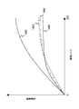
そこで、色剤量の削減を、モノクロプリントの色剤使用量を基準として最小限に抑制しながら、高画質化を行うため、以下の検討を行った。図14は、縦軸に色剤使用量、横軸にパッチに対して色相および明度の異なる印字を行い、当該パッチに対する色剤使用量順に、パッチを並べた色剤使用量特性グラフである。なお、色剤使用量の少ない側(紙面左手側)は、ハイライト色に相当し、色剤使用量の多い側(紙面右手側)が、シャドウ色に相当する。印刷モードは、ライン1200が通常モード、ライン1202がモノクロ基準モード、およびライン1204が固定係数=0.5としたときの固定係数モードに相当する。
4). Examination of Colorant Amount Reduction Mode and Image Quality As described above, each of the colorant reduction modes can reduce the colorant, but it is not sufficient to achieve both the reduction of the colorant and the image quality.
Therefore, in order to improve the image quality while minimizing the reduction in the amount of colorant based on the amount of colorant used for monochrome printing, the following examination was performed. FIG. 14 is a colorant usage characteristic graph in which patches are arranged in order of the colorant usage amount for the patch, in which the vertical axis indicates colorant usage amount, and the horizontal axis indicates a different hue and lightness for the patch. Note that the side with less colorant usage (the left hand side of the paper) corresponds to the highlight color, and the side with higher colorant usage (the right hand side of the paper) corresponds to the shadow color. The print mode corresponds to the normal mode for the
カラー印刷される出力画像の心理的効果について考えると、ハイライト色側は色が薄いので、使用される色剤量が少なくさらに減少させてしまうとハイライト色が飛んでしまうという問題が生じる。一方、シャドウ側は、心理的効果は大きいものの、色剤使用量が高いので色剤量を削減するマージンを確保しやすいということができる。また、シャドウ色側で色剤量を減少させても、ドットの潰れや飛びには直結しないので、出力画像の認識性を低下させるポリシーではない。 Considering the psychological effect of the color printed output image, the highlight color side is light in color, so that there is a problem that if the amount of the colorant used is small and further reduced, the highlight color will fly out. On the other hand, the shadow side has a great psychological effect, but the amount of colorant used is high, so it can be said that it is easy to secure a margin for reducing the amount of colorant. Further, even if the amount of the colorant is reduced on the shadow color side, it is not directly linked to dot crushing or skipping, so this is not a policy for reducing the recognizability of the output image.
ところで、ハイライト色とシャドウ色との間を連続するいわゆる中間色域は、カラー画像を最も特徴付ける領域であり、シェーディングの連続性および画像ドットの保存性は、図13に示すように、カラー画像がユーザに対して与える心理的効果に大きな影響を与えることが判明した。特に、画像データばかりではなく、ビジネス文章などでは、表の背景として中間濃度として与えられる淡い色が多用され、淡いながらも個々の色分けに意味を持たせる場合が多い。このため、ハイライト色から中間濃度領域で画像ドットおよびコントラストを保持することは、カラー画像の与える心理的効果にとって重要であり、色剤使用量低減モードにおけるハイライト色から中間色にかけて画像ドットを保存紙ながらコントラストを向上させることが、色剤量減少によるカラー画像に対する心理的影響を緩和することができることが判明した。 By the way, a so-called intermediate color gamut that is continuous between the highlight color and the shadow color is an area that characterizes the color image most. The continuity of shading and the preservation of image dots are as shown in FIG. It was found to have a great influence on the psychological effects on users. In particular, not only image data, but also business texts, etc., a light color given as an intermediate density is often used as a background of a table. For this reason, maintaining image dots and contrast in the intermediate density region from the highlight color is important for the psychological effects of color images, and image dots are stored from the highlight color to the intermediate color in the colorant usage reduction mode. It has been found that improving the contrast while using paper can mitigate the psychological effect on the color image due to the decrease in the amount of colorant.
ハイライト色から中間色にかけてのコントラストを向上させるためには、図12および図14に示すように単純にモノクロ基準モードの色剤量を基準として増加させるよりも、固定係数モードの色剤量を基準として使用することが望ましい。この理由は、図12に示されるように、モノクロ基準モードでは、色剤削減特性が階調だけでなく、色相にも影響されるので、色相、例えばYなどでは極端に色剤量が削減されてしまうなど、画像が含む色データにより補正効果のスケーラビリティが得られないためである。 In order to improve the contrast from the highlight color to the intermediate color, the colorant amount in the fixed coefficient mode is used as a reference rather than simply increasing the colorant amount in the monochrome reference mode as shown in FIGS. It is desirable to use as The reason for this is that, as shown in FIG. 12, in the monochrome reference mode, the colorant reduction characteristic is affected not only by the gradation but also by the hue. This is because the scalability of the correction effect cannot be obtained by the color data included in the image.
これに対して、固定係数を乗算した場合は、どの色相にも均等に補正効果がかかる。このため、色相によって階調バランスが崩れるといった中間色の色再現性に対する悪影響を最小限にすることができる。 On the other hand, when the fixed coefficient is multiplied, the correction effect is equally applied to any hue. For this reason, it is possible to minimize the adverse effect on the color reproducibility of the intermediate color, such as the gradation balance being lost depending on the hue.
また、固定係数の値については、30%〜60%に設定することで、図13に示すように、識別可能な画像を得ることができる。なお、固定係数を60%以上に設定する場合、モノクロ基準の色剤使用量までの色剤量削減が実質的に困難になる場合がある。なお、下限値は、画像の識別性が確保できる限り、特に制限はないが、画像品質的な観点から、モノクロ基準モードでの色剤使用量以上となる係数値とする必要がある。以上の点から、固定係数の範囲として、下記式(2)で示される範囲を採用することができる。 Further, by setting the value of the fixed coefficient to 30% to 60%, an identifiable image can be obtained as shown in FIG. When the fixed coefficient is set to 60% or more, it may be difficult to reduce the colorant amount up to the monochrome-based colorant usage amount. The lower limit value is not particularly limited as long as the image identifiability can be ensured. However, from the viewpoint of image quality, the lower limit value needs to be a coefficient value that is equal to or greater than the colorant usage amount in the monochrome reference mode. From the above points, the range represented by the following formula (2) can be adopted as the range of the fixed coefficient.

5.色剤使用量のスイッチング
画像品質を保存させながらモノクロ基準モードに近いインク使用量を実現するためには、ハイライト色から中間色までについての画質を確保する上でモノクロ基準モードを超える色剤使用量としなければならず、このためシャドウ色側で色剤使用量を削減する必要がある。この場合、所定のしきい値を超えたシャドウ色側でモノクロ基準モードでの色剤使用量よりも色剤使用量を減少させることで色剤使用量を管理するように、色剤使用量を切換える。
5). Colorant usage switching In order to achieve ink usage that is close to the monochrome standard mode while preserving image quality, the colorant usage that exceeds the monochrome standard mode is required to ensure image quality from highlight colors to intermediate colors. Therefore, it is necessary to reduce the amount of colorant used on the shadow color side. In this case, the amount of colorant used is controlled so that the amount of colorant used is managed by reducing the amount of colorant used on the shadow color side that exceeds a predetermined threshold, compared to the amount of colorant used in the monochrome reference mode. Switch.
本実施形態では、色剤使用量を、モノクロ基準モードを規準とし、モノクロ基準モードに最も近くなるように、ハイライト色から中間色にかけて色剤使用量を増加させ、シャドウ色側で色剤使用量を減少させる。図15は、本実施形態による色剤使用量削減処理の説明図である。フルカラー出力時の色剤使用量は、ライン1500で示される。モノクロ基準モードを使用する場合の色剤使用量は、ライン1502で与えられ、また、固定係数モードでの色剤使用量は、ライン1504で与えられる。
In the present embodiment, the colorant usage is based on the monochrome reference mode, and the colorant usage is increased from the highlight color to the intermediate color so as to be closest to the monochrome reference mode, and the colorant usage is on the shadow color side. Decrease. FIG. 15 is an explanatory diagram of the colorant usage reduction process according to the present embodiment. The amount of colorant used during full color output is indicated by
固定係数モードのライン1504は、モノクロ基準モードよりもハイライト色〜中間色の範囲では、色剤使用量が多く、この結果、画質的には、モノクロ基準モードよりも高画質を与える。一方で、ハイライト色からシャドウ色まで固定係数モードを利用すれば色剤削減による画質劣化を最小限とすることができるものの、色剤使用量の削減量という意味では充分ということができない。このため、本実施形態では、ハイライト色〜シャドウ色までの間で、色剤削減量をスイッチングする。以下、色剤使用量のスイッチング処理について説明する。
The fixed
モノクロ基準モードおよび固定係数モードの色剤使用量は、色相、明度により異なることが想定されるので、第2LUT626および第3LUT628の作成時、交点の存在を検査し、または予め設定されたしきい値を利用して、第2LUTを修正する。なお、本実施形態では、色剤使用量を切換えるための特徴ポイントという意味で、交点および外部設定されるしきい値について、以下、いずれもしきい値として参照する。なお、本実施形態では、しきい値レベルは、図中矢線で示す。また、トン実施形態では、しきい値は、色剤使用量について設定するものとして説明するが、所定の色相と、色剤使用量とが関連付けられている限り、色相ごと、入力色空間座標に関してしきい値を設定することもでき、この場合、色相ごとに異なるしきい値を設けてもよい。
Since the amount of colorant used in the monochrome reference mode and the fixed coefficient mode is assumed to vary depending on the hue and lightness, the existence of an intersection is inspected when the
図15(a)には、図14で説明した特性曲線が、ハイライト色からシャドウ色の間の適切なポイントで交点を与える場合の実施形態である。また、図15(b)、図15(c)は、ハイライト色からシャドウ色に至る適切なポイントに交点が存在しない場合の実施形態である。本実施形態では、交点が存在する場合、交点をシャドウ側に超えた領域について交点を共有し、かつなめらかに固定係数モードの特性曲線に連続する補間関数1506を生成し、当該補間関数1506で与えられる色剤使用量を与えるように、第2LUTの値を修正する。
FIG. 15A shows an embodiment in which the characteristic curve described in FIG. 14 gives an intersection at an appropriate point between the highlight color and the shadow color. FIG. 15B and FIG. 15C are embodiments in the case where no intersection exists at an appropriate point from the highlight color to the shadow color. In the present embodiment, when there is an intersection, an intersection function is shared for a region that exceeds the intersection on the shadow side, and an
また、色剤使用量に関して予め設定したしきい値を使用する場合、補間関数1506は、しきい値に相当する色剤使用量を挟んで、固定係数モードの特性曲線のポイントを供給し、かつなめらかに連続するように設定される。いずれの場合でも、補間関数1506は、使用する固定係数モードの特性曲線とポイントを共有し、当該ポイントで、なめらかに特性曲線に接続させながら、ハイライト色からシャドウ色までの色剤使用量の積分値CRealが、モノクロ基準モードの対応する範囲の積分値Cstandとの間の絶対値の差|CReal−Cstand|を最小化するように、補間関数、スプライン関数の各係数や関数種類を決定する。この補間関数は、第2LUT626の該当するサンプルポイントの入力色空間座標を、補間関数で与えられる色剤使用量の色差を最小とするCMYデータに変換させるように決定され、補間関数で与えられた色剤使用量を使用して、第2LUT626を作成すると同様の処理を使用してモノクロ基準モードの第2LUT626を修正するために使用される。なお、しきい値の設定は色剤使用量の他、入力色空間座標値、HSV、またはsqrt{(a*)2+(b*)2}などの色相値などに関して設定することができる。
Also, when using a preset threshold value for the colorant usage amount, the
さらに他の実施形態では、カラー画像のうち、文字オブジェクトや線画オブジェクトに対して色剤低減処理をしない設定を行うことも可能である。この処理は、本実施形態を、ラスタデータとフォントデータとを分離して出力データを作成する場合に好適に適用することができる。この実施形態では、さらに、文字オブジェクトや線画オブジェクトと、それ以外のラスタデータとについて、異なる色剤使用量削減処理を適用することもできる。文字オブジェクトや線画オブジェクトに対して異なる色剤使用量削減処理を適用し、コントラストを改善することで、色剤使用量の削減効果は若干劣化するものの、文字オブジェクトや線画オブジェクトの視認性を確保しつつ、画像データ全体では色剤使用量を削減させることができる。 In still another embodiment, it is possible to perform a setting not to perform colorant reduction processing on a character object or a line drawing object in a color image. This processing can be preferably applied to the case where the raster data and font data are separated to create output data. In this embodiment, it is also possible to apply different colorant usage reduction processing to character objects and line drawing objects, and other raster data. By applying different colorant usage reduction processing to text objects and line drawing objects and improving contrast, the effect of reducing colorant usage is slightly degraded, but the visibility of text objects and line drawing objects is ensured. On the other hand, the amount of colorant used can be reduced in the entire image data.
<セクション3:色剤使用量削減処理>
図16は、画像形成方法の色剤使用量削減モードの実施形態のフローチャートを示す。図16の処理は、ステップS1600から開始し、ステップS1601で入力色空間座標を取得する。ステップS1602では、入力色空間座標が固定係数モードでしきい値を超えた色剤使用量を必要とするか否かを判断する。なお、しきい値は、ユーザが任意に設定することもできるし、また固定係数モードの特性曲線とモノクロ基準モードの特性曲線との間に交点が存在する場合、当該交点を使用することもできる。ステップS1602で、入力色空間座標が、固定係数モードで、しきい値を超えた色剤使用量を要求する場合(yes)、処理をステップS1604に分岐させる。一方、ステップS1602で、入力色空間座標がしきい値を超えた色剤使用量以下の場合(no)、ステップS1603で第3LUT628を使用して固定係数モードで色剤削減した色変換を実行する。
<Section 3: Colorant usage reduction processing>
FIG. 16 shows a flowchart of an embodiment of a colorant usage reduction mode of the image forming method. The processing in FIG. 16 starts from step S1600, and input color space coordinates are acquired in step S1601. In step S1602, it is determined whether or not a colorant usage amount whose input color space coordinates exceed a threshold value in the fixed coefficient mode is required. Note that the threshold value can be arbitrarily set by the user, and when an intersection exists between the characteristic curve of the fixed coefficient mode and the characteristic curve of the monochrome reference mode, the intersection can be used. . In step S1602, when the input color space coordinate is in the fixed coefficient mode and a colorant usage amount exceeding the threshold is requested (yes), the process is branched to step S1604. On the other hand, if the input color space coordinate is less than or equal to the colorant usage amount exceeding the threshold value in step S1602 (no), color conversion with the colorant reduced in the fixed coefficient mode is executed using the third LUT 628 in step S1603. .
ステップS1602で、入力色空間座標が固定係数モードについて設定した、しきい値を超えた色剤使用量を要求する場合(yes)、ステップS1604で、第2LUT626を使用して色剤使用量を削減する色変換を実行する。なお、第2LUT626は、この段階ではモノクロ基準モードそのままのデータではなく、しきい値以上では、補間関数により与えられる色剤使用量に対応するCMYデータがエントリされている。
In step S1602, when the colorant usage amount that exceeds the threshold value set for the fixed coefficient mode in the input color space coordinates is requested (yes), the
その後、入力色空間座標のすべての色変換が終了した後、ステップS1605で後続の画像処理を施して、CMYK系の出力データを生成させ、プリンタに送信して印刷を実行させ、ステップS1606で処理を終了させる。図16に示した実施形態によれば、ハイライト色のコントラストを確保しながら、シャドウ色にかけてモノクロ基準モードに最も近い色剤使用量で印刷が可能となり、画質と色剤量削減との間のトレードオフの関係を改善することができる。 Thereafter, after all color conversions of the input color space coordinates are completed, subsequent image processing is performed in step S1605 to generate CMYK output data, which is transmitted to the printer to be printed, and processed in step S1606. End. According to the embodiment shown in FIG. 16, it is possible to perform printing with the colorant usage amount closest to the monochrome reference mode over the shadow color while ensuring the contrast of the highlight color, and between the image quality and the colorant amount reduction. The trade-off relationship can be improved.
図17は、本実施形態の色剤使用量削減モードと、固定係数モード、およびモノクロ基準モードの色剤使用量削減を、複数の画像について測定した場合の実施例を示す。図17では、色剤使用量削減の基準としてモノクロ基準モードの色剤使用量を使用し、固定係数モードおよび本実施形態の色剤量削減モードについて、相対的な削減量を示したものである。なお、図17では、紙面左手側から順に、同一の画像についてのモノクロ基準モード、固定係数モード、本実施形態のモードの色剤使用量が対として示されている。 FIG. 17 shows an example where the colorant usage reduction mode, the fixed coefficient mode, and the monochrome reference mode reduction in this embodiment are measured for a plurality of images. FIG. 17 shows the relative reduction amount for the fixed coefficient mode and the colorant amount reduction mode of the present embodiment, using the colorant usage amount of the monochrome reference mode as a reference for reducing the colorant usage amount. . In FIG. 17, the monochrome reference mode, the fixed coefficient mode, and the colorant usage amount of the mode of this embodiment for the same image are shown as a pair in order from the left hand side of the drawing.
図17に示すように、固定係数モードでは概ねモノクロ基準モードよりも色剤使用量が減少しているが、この理由は、シャドウ色部分についても固定係数が乗算されるため、ハイライト部分ではモノクロ基準モードよりも色剤使用量を増加させた場合でも積分値としては低くなるためと推定される。また、固定係数モードでは、画像によって色剤使用量の変動幅が約40%近く低い側に変動し、固定係数モード単独では、画像ごとの画質の保証性が充分ではないことがわかった。一方、本実施形態の色剤削減モードでは、モノクロ基準モードに対して色剤使用量が概ね±10%程度の範囲内で一致しており、ほぼモノクロ基準モードに対応する色剤使用量が与えられているのが示されている。 As shown in FIG. 17, in the fixed coefficient mode, the amount of colorant used is generally smaller than that in the monochrome reference mode. This is because the shadow color portion is also multiplied by a fixed coefficient. It is estimated that the integrated value is lower even when the colorant usage is increased than in the reference mode. Further, in the fixed coefficient mode, the variation range of the colorant usage amount varies depending on the image to the lower side of about 40%, and it was found that the image quality assurance for each image is not sufficient in the fixed coefficient mode alone. On the other hand, in the colorant reduction mode of the present embodiment, the colorant usage amount matches the monochrome standard mode within a range of about ± 10%, and the colorant usage amount corresponding to the monochrome standard mode is given. Is shown.
図17に示されるように、本実施形態の色剤削減モードでは、モノクロ基準モードまたは固定係数モード単独で色剤量を削減する場合に比較して、画像間での色剤削減量の安定性が改善でき、この結果、画質を保証しながら色剤を削減することができることがわかる。 As shown in FIG. 17, in the colorant reduction mode of the present embodiment, the stability of the colorant reduction amount between images is reduced as compared with the case of reducing the colorant amount in the monochrome reference mode or the fixed coefficient mode alone. As a result, it can be seen that the colorant can be reduced while ensuring the image quality.
なお、本実施形態では、ハイライト色〜中間色を固定係数モードとし、シャドウ色を補正関数で与えられるモノクロ基準モードとして色変換を行うものとして説明したが、いわゆる特色の場合、特色に応じた色再現特性が考えられ、CMYKおよび特色を含め、色相、明度などハイライト色〜中間色をモノクロ基準モードとし、シャドウ色を固定係数モードとして色変換することも可能である。 In the present embodiment, the highlight color to the intermediate color are set as the fixed coefficient mode, and the shadow conversion is performed as the monochrome reference mode given by the correction function. However, in the case of a so-called spot color, a color corresponding to the spot color is used. Reproduction characteristics are conceivable, and it is also possible to perform color conversion using highlight colors to intermediate colors such as hue and brightness, including CMYK and special colors, as a monochrome reference mode and a shadow color as a fixed coefficient mode.
図18は、本実施形態による色剤使用量を削減した画像を、フルカラー印刷、モノクロ基準モードおよび固定係数モードと共に比較した図である。図18(a)がフルカラーモード、図18(b)がモノクロ印刷、図18(c)が固定係数モード、図18(d)が本実施形態の色剤使用量削減モードである。図18に示されるように、モノクロ印刷(図18(b))の場合には、カラー情報が失われてしまっている。一方、固定計数モード(図18(c)では、フルカラー印刷の場合に比較してシャドウ色が、係数固定の分だけ著しく薄くなっているのがわかる。 FIG. 18 is a diagram comparing an image with a reduced amount of colorant used according to the present embodiment together with full-color printing, a monochrome reference mode, and a fixed coefficient mode. 18A shows the full color mode, FIG. 18B shows monochrome printing, FIG. 18C shows the fixed coefficient mode, and FIG. 18D shows the colorant usage reduction mode of this embodiment. As shown in FIG. 18, in the case of monochrome printing (FIG. 18B), the color information has been lost. On the other hand, in the fixed count mode (FIG. 18C), it can be seen that the shadow color is significantly lighter than the case of full color printing by the fixed coefficient.
一方、本実施形態の色剤使用量削減モードでは、ハイライト色から中間色までのコントラストが改善されており、固定係数モードと比較しても補間関数でシャドウ色の色剤使用量を大きく削減できる事に対応し、その分だけハイライト色から中間色の色剤使用量を高められるので、カラー画像が与える心理的効果は、フルカラー画像に近いものとなっていることが示された。 On the other hand, in the colorant usage reduction mode of the present embodiment, the contrast from the highlight color to the intermediate color is improved, and the colorant usage of the shadow color can be greatly reduced by the interpolation function even compared to the fixed coefficient mode. Corresponding to this, the amount of colorant used in the intermediate color can be increased from the highlight color accordingly, indicating that the psychological effect of the color image is close to that of a full color image.
図19は、本実施形態による階調再現特性の概略図を示す。図19では、縦軸に印刷出力の画像濃度(反射濃度)を取り、横軸に階調レベルを、8ビット分解能としたものとして示す。ライン1900は、フルカラー出力の階調再現特性であり、ライン1902が、NTSC変換を使用した場合のモノクロ基準モードによる画像濃度特性を示す。また、ライン1904は、固定係数モードでの画像濃度特性を示し、ライン1906が、本実施形態の色剤使用量削減モードの画像濃度特性を示す。
FIG. 19 is a schematic diagram of gradation reproduction characteristics according to the present embodiment. In FIG. 19, the vertical axis represents the image density (reflection density) of the print output, and the horizontal axis represents the gradation level with 8-bit resolution. A
図18に示すように、モノクロ基準モード、固定係数モード、および本実施形態の色剤使用量削減モードは、同一の階調レベルで見た場合、色剤使用量削減の結果、いずれもフルカラー出力よりも画像濃度が低くされている。また、固定係数モードでは、ライン1904で示されるように、ハイライト色から中間色までの色剤使用量をモノクロ基準モードよりも高くした場合、ハイライト色からシャドウ色まで同一の係数を乗算して色剤使用量をモノクロ基準モードに近づけようとすると、ハイライト色から中間色までの色剤使用量の増加量に制限を受けることになり、固定係数をハイライト色から中間色までのコントラストを保存させながら出力する点で制限を受ける。
As shown in FIG. 18, the monochrome reference mode, the fixed coefficient mode, and the colorant usage reduction mode of this embodiment are all output in full color as a result of the reduction of the colorant usage when viewed at the same gradation level. The image density is lower than that. In the fixed coefficient mode, as shown by a
一方、本実施形態の色剤使用量削減モードに対応するライン1906は、交点または設定されたしきい値を挟んで補正関数で、シャドウ色側の色剤使用量を、ハイライト色から中間色までの色剤使用量増加分に見合うように削減させることで、ハイライト色からシャドウ色までの全色剤使用量、すなわち積分色剤使用量を、モノクロ基準モードに最も近づけることが可能となる。この場合、ハイライト色から中間色にかけては固定係数モードよりも高いコントラストで画像形成されるので、固定係数モードに比較し、カラー画像がユーザに与える心理的効果をよりフルカラー画像に近似させることができるものと考えられる。
On the other hand, a
本実施形態の色剤削減モードは、画像形成装置の画像処理専用のASICとして実装することができる。また、他の実施形態では、パーソナルコンピュータ、ワークステーションその他情報処理装置のプリンタドライバとして実装することができる。さらに、本実施形態の色剤使用量削減処理を実行するモジュールは、CMM変換処理自体に実装させることができる。また、本実施形態の色剤使用量削減処理を実行するモジュールは、色剤使用量を削減させるための色相補正LUTとして実装することもでき、色相補正LUTとして実装する場合、BG/UCR処理の前処理モジュールまたは後処理モジュールとして実装することができる。 The colorant reduction mode of this embodiment can be implemented as an ASIC dedicated to image processing of the image forming apparatus. In other embodiments, it can be implemented as a printer driver for a personal computer, workstation, or other information processing apparatus. Furthermore, the module for executing the colorant usage reduction process of the present embodiment can be implemented in the CMM conversion process itself. Further, the module for executing the colorant usage reduction process of the present embodiment can be implemented as a hue correction LUT for reducing the colorant usage. When implemented as a hue correction LUT, the module for BG / UCR processing is implemented. It can be implemented as a pre-processing module or a post-processing module.
また、以上の処理は、LUTや補正式を画像処理過程において適用するものであるが、狙いとする色剤使用量(s%)や基準とする固定係数をユーザーによって記録装置のコントロールパネルや制御プログラム上から入力し、オンザフライでリアルタイムに補正LUTや補正式を演算させる、あるいは、予め作成しておいた複数の補正用LUTなどの中から、ユーザ入力に応じて、例えば固定係数値などを選択させるようにしてもよい。 In the above processing, the LUT and the correction formula are applied in the image processing process. However, the target colorant usage (s%) and the reference fixed coefficient are set by the user on the control panel of the recording apparatus or the control. Input from the program and calculate the correction LUT and correction formula in real time on-the-fly, or select a fixed coefficient value, for example, from a plurality of correction LUTs created in advance according to user input You may make it make it.
また、色剤使用量低減処理用の各種LUTや中間調処理のためのディザパターン、補間関数などについては、ソフトウエアとしてプログラム上から呼出すように実装することもできるし、画像処理速度やCPU処理能力に応じてROMやRAMに記憶させてハードウエア処理に使用することもできる。さらに、スタンドアロンで画像処理から印刷処理までをこなす記録装置や、複数の機器を組み合わせて印刷処理までをこなす記録システムなどの組込みアプリケーションとして実装することができる。 In addition, various LUTs for colorant usage reduction processing, dither patterns for halftone processing, interpolation functions, etc. can be implemented as software calls from the program, and image processing speed and CPU processing can be implemented. It can be stored in a ROM or RAM according to the capability and used for hardware processing. Furthermore, it can be implemented as a built-in application such as a recording apparatus that performs stand-alone processing from image processing to printing processing, or a recording system that performs printing processing by combining a plurality of devices.
本実施形態の色剤使用量低減処理に使用するLUT、補正関数、およびそれらを用いて色剤使用量低減処理を行うプログラムは、アセンブラ、Cなどのレガシープログラミング言語、C++、JAVA(登録商標)などのオブジェクト指向プログラミング言語等を使用して実装することができ、これらのプログラムは、CD−ROM、DVDといったコンピュータ可読な記録媒体に格納して頒布することができる。また、本実施形態のプログラムは、インターネットなどのネットワークを介し、HTTPまたはFTPなどのファイル転送プロトコルを使用して伝送により頒布することができる。 The LUT used for the colorant usage reduction process of this embodiment, the correction function, and the program for performing the colorant usage reduction process using them are legacy programming languages such as assembler and C, C ++, JAVA (registered trademark). The program can be implemented using an object-oriented programming language or the like, and these programs can be stored and distributed in a computer-readable recording medium such as a CD-ROM or a DVD. Further, the program of this embodiment can be distributed by transmission using a file transfer protocol such as HTTP or FTP via a network such as the Internet.
さらに、本実施形態の色剤使用量削減処理は、インクジェット方式による画像形成の他、電子写真方式、熱転写記録方式など、種々の記録方式を使用する画像形成装置に対しても実装することができる。 Furthermore, the colorant usage reduction process of the present embodiment can be implemented not only for image formation by the ink jet method but also for image forming apparatuses that use various recording methods such as an electrophotographic method and a thermal transfer recording method. .
以上説明したように、本発明によれば、フルカラー印刷の色剤使用量低減モードにおいて、ユーザが分かりやすい基準、具体的にはモノクロ印刷モードでの色剤使用量や色剤コストを目安に、色剤使用量、色剤コストを含む印刷コストを低減し、さらに色剤使用量低減による色の見えにくさなどのカラー画像の心理的効果の低下を抑制し、色剤使用量削減と、カラー画像の心理的効果を両立させることができる。 As described above, according to the present invention, in the colorant usage reduction mode of full-color printing, the user-friendly standard, specifically, the colorant usage and colorant cost in the monochrome printing mode as a guideline, Reduces printing costs, including colorant usage and colorant cost, and further suppresses the reduction of color image psychological effects such as difficulty in seeing color due to colorant usage reduction. Both psychological effects of images can be achieved.
これまで本実施形態につき説明してきたが、本発明は、上述した実施形態に限定されるものではなく、他の実施形態、追加、変更、削除など、当業者が想到することができる範囲内で変更することができ、いずれの態様においても本発明の作用・効果を奏する限り、本発明の範囲に含まれるものである。 Although the present embodiment has been described so far, the present invention is not limited to the above-described embodiment, and other embodiments, additions, changes, deletions, and the like can be conceived by those skilled in the art. It can be changed, and any aspect is within the scope of the present invention as long as the effects and effects of the present invention are exhibited.
100…画像処理装置、110…制御部、112…中央処理装置(CPU)、114…ROM、116…RAM、118…NVRAM、120…ユーザI/F、122…ASIC、126…操作入力部、128…各種センサ、130…外部I/F、140…画像形成部、142…印刷制御部、144…駆動制御部、146…高電圧制御部、600…画像処理システム、610…画像処理装置、612…アプリケーション、614…オペレーティングシステム、616…プリンタドライバ、618…色変換処理部、620…色剤量計算部、622…色変換テーブル、624〜628…各LUT、630…PDL処理部、640…画像形成部(プリンタ)
DESCRIPTION OF
Claims (10)
画像データを取得するアプリケーション手段と、
前記画像データの入力色空間座標データに基づいて少なくともCMYデータを取得する色変換手段と、
前記色変換手段の出力する前記CMYデータを使用してCMYKデータを作成し出力データを生成する出力データ生成手段とを備え、
前記色変換手段は、
前記入力色空間座標データを最適再現したフルカラー画像を与えるための前記少なくともCMYデータを与える最適色再現用データ構造と、
前記最適再現したフルカラー画像の出力時に、前記入力色空間座標データのNTSC変換により与えられるモノクロ出力時の色剤使用量を基準値として、前記基準値よりも色剤使用量を削減させて出力するための少なくともCMYデータを与える色材削減用データ構造とを含み、
前記色材削減用データ構造は、出力画像が与える心理的効果が大きな色相に対しては前記色剤使用量を前記基準値よりも増加させ、前記出力画像が与える心理的効果が小さい色相に対しては前記色剤使用量を前記基準値よりも減少させた前記CMYデータを与える、色材削減用データ構造であることを特徴とする、画像処理装置。 An image processing apparatus that performs color conversion of image data,
Application means for obtaining image data;
Color conversion means for acquiring at least CMY data based on input color space coordinate data of the image data;
Output data generation means for generating CMYK data using the CMY data output from the color conversion means and generating output data;
The color conversion means includes
An optimal color reproduction data structure for providing at least CMY data for providing a full color image optimally reproducing the input color space coordinate data;
When the optimally reproduced full color image is output, the colorant usage amount at the time of monochrome output given by NTSC conversion of the input color space coordinate data is used as a reference value, and the colorant usage amount is reduced from the reference value for output. A color material reduction data structure for providing at least CMY data for
The color material reduction data structure increases the amount of the colorant used for a hue having a large psychological effect given by the output image, and reduces the psychological effect given by the output image to a hue having a small psychological effect. An image processing apparatus having a color material reduction data structure that provides the CMY data in which the colorant usage is reduced from the reference value.
前記基準値よりも減少させた前記色剤使用量は、総色剤使用量と前記モノクロ基準モードにおける総色材使用量との差を最小にするように前記しきい値を挟んでなめらかに色剤使用量を変化させる補間関数により与えられる、請求項3に記載の画像処理装置。 The colorant usage amount increased from the reference value is given as a colorant usage amount in the fixed coefficient mode,
The colorant usage amount reduced from the reference value is a smooth color with the threshold value interposed therebetween so as to minimize the difference between the total colorant usage amount and the total colorant usage amount in the monochrome reference mode. The image processing apparatus according to claim 3, wherein the image processing apparatus is given by an interpolation function that changes the amount of agent used.
アプリケーション手段が作成した前記画像データを色変換手段に渡すステップと、
前記色変換手段により前記画像データの入力色空間座標データから、少なくともCMYデータを取得するステップと、
前記色変換手段が出力する前記CMYデータを使用してCMYKデータを作成し出力データを生成するステップとを実行し、
前記少なくともCMYデータを取得するステップは、
フルカラー画像を最適再現するモードか、またはフルカラー画像を色剤使用量を削減して再現するモードかを判断するステップと、
フルカラー画像を最適再現するモードと判断した場合には、前記入力色空間座標データのNTSC変換により与えられるモノクロ出力時の色剤使用量を基準値として、前記基準値よりも色剤使用量を削減させて出力するための少なくともCMYデータを与える色材削減用データ構造を参照するステップと、
前記フルカラー画像を色剤使用量を削減して再現するモードと判断した場合には、出力画像が与える心理的効果が大きな色相に対しては前記色剤使用量を前記基準値よりも増加させ、前記出力画像が与える心理的効果が小さい色相に対しては前記色剤使用量を前記基準値よりも減少させた前記CMYデータを与えるための色材削減用データ構造を参照するステップと
を含む、画像処理方法。 An image processing method for color-converting image data, wherein the image processing method includes:
Passing the image data created by the application means to the color conversion means;
Obtaining at least CMY data from input color space coordinate data of the image data by the color conversion means;
Generating CMYK data using the CMY data output by the color conversion means and generating output data;
Obtaining at least the CMY data comprises:
Determining whether to optimally reproduce a full-color image or to reproduce a full-color image with reduced colorant usage;
When it is determined that the mode is to reproduce the full color image optimally, the colorant usage amount is reduced from the reference value with the colorant usage amount at the time of monochrome output given by NTSC conversion of the input color space coordinate data as a reference value. Referring to a data structure for color material reduction that gives at least CMY data for output,
When it is determined that the full-color image is a mode for reproducing the colorant using a reduced amount, the hue used by the output image is increased for the hue having a large psychological effect. Referring to a color material reduction data structure for providing the CMY data in which the colorant usage amount is reduced from the reference value for a hue having a small psychological effect provided by the output image. Image processing method.
前記基準値よりも減少させた前記色剤使用量は、総色剤使用量と前記モノクロ基準モードにおける総色材使用量との差を最小にするように前記しきい値を挟んでなめらかに色剤使用量を変化させる補間関数により与えられる、請求項7に記載の画像処理方法。 The colorant usage amount increased from the reference value is given as a colorant usage amount in the fixed coefficient mode,
The colorant usage amount reduced from the reference value is a smooth color with the threshold value interposed therebetween so as to minimize the difference between the total colorant usage amount and the total colorant usage amount in the monochrome reference mode. The image processing method according to claim 7, wherein the image processing method is given by an interpolation function that changes the amount of agent used.
Priority Applications (5)
| Application Number | Priority Date | Filing Date | Title |
|---|---|---|---|
| JP2008059274A JP4776646B2 (en) | 2008-03-10 | 2008-03-10 | Image processing apparatus, image processing method, program, and recording medium |
| CN200980107945.0A CN101965726B (en) | 2008-03-10 | 2009-02-26 | Image processing apparatus, and image processing method |
| EP09719321.3A EP2250803B1 (en) | 2008-03-10 | 2009-02-26 | Image processing apparatus, image processing method, and computer-readable recording medium storing image processing program |
| PCT/JP2009/054119 WO2009113437A1 (en) | 2008-03-10 | 2009-02-26 | Image processing apparatus, image processing method, and computer-readable recording medium storing image processing program |
| US12/919,771 US8804219B2 (en) | 2008-03-10 | 2009-02-26 | Image processing apparatus, image processing method, and computer-readable recording medium storing image processing program for color conversion of image data |
Applications Claiming Priority (1)
| Application Number | Priority Date | Filing Date | Title |
|---|---|---|---|
| JP2008059274A JP4776646B2 (en) | 2008-03-10 | 2008-03-10 | Image processing apparatus, image processing method, program, and recording medium |
Publications (3)
| Publication Number | Publication Date |
|---|---|
| JP2009218779A JP2009218779A (en) | 2009-09-24 |
| JP2009218779A5 JP2009218779A5 (en) | 2010-05-13 |
| JP4776646B2 true JP4776646B2 (en) | 2011-09-21 |
Family
ID=41065106
Family Applications (1)
| Application Number | Title | Priority Date | Filing Date |
|---|---|---|---|
| JP2008059274A Expired - Fee Related JP4776646B2 (en) | 2008-03-10 | 2008-03-10 | Image processing apparatus, image processing method, program, and recording medium |
Country Status (5)
| Country | Link |
|---|---|
| US (1) | US8804219B2 (en) |
| EP (1) | EP2250803B1 (en) |
| JP (1) | JP4776646B2 (en) |
| CN (1) | CN101965726B (en) |
| WO (1) | WO2009113437A1 (en) |
Families Citing this family (10)
| Publication number | Priority date | Publication date | Assignee | Title |
|---|---|---|---|---|
| US8456720B2 (en) * | 2009-10-19 | 2013-06-04 | Xerox Corporation | Reducing noise induced by color mixing spot color recipe search |
| US8711453B2 (en) | 2010-05-24 | 2014-04-29 | Canon Kabushiki Kaisha | Data processing apparatus and data processing method for reducing an uneven color made up of two or more ink colors |
| JP5605094B2 (en) * | 2010-08-30 | 2014-10-15 | 株式会社リコー | Image processing apparatus, image processing method, image forming apparatus, program, and recording medium |
| US8947737B2 (en) * | 2011-01-31 | 2015-02-03 | Seiko Epson Corporation | Image processing that generates and density corrects ink amount data |
| JP5760469B2 (en) * | 2011-02-07 | 2015-08-12 | セイコーエプソン株式会社 | Image processing apparatus and image processing method |
| JP5494641B2 (en) * | 2011-12-27 | 2014-05-21 | コニカミノルタ株式会社 | Color conversion table creation device, color conversion table creation method and program |
| US10186705B2 (en) * | 2013-11-25 | 2019-01-22 | The Regents Of The University Of California | Instrumentation to dry-deliver SLMP particles to the lithium-ion electrode |
| WO2017159460A1 (en) * | 2016-03-17 | 2017-09-21 | セイコーエプソン株式会社 | Color correction table creating method, color correction table creating device, and program |
| JP2018069593A (en) * | 2016-10-31 | 2018-05-10 | 京セラドキュメントソリューションズ株式会社 | Monochromatic image formation apparatus |
| CN109410308A (en) * | 2018-09-29 | 2019-03-01 | Oppo广东移动通信有限公司 | Image processing method and device, electronic equipment, computer readable storage medium |
Family Cites Families (46)
| Publication number | Priority date | Publication date | Assignee | Title |
|---|---|---|---|---|
| JP3268712B2 (en) * | 1994-12-28 | 2002-03-25 | キヤノン株式会社 | Image forming method and apparatus |
| JP3376194B2 (en) * | 1995-12-15 | 2003-02-10 | キヤノン株式会社 | Image processing apparatus and method |
| JPH09216419A (en) * | 1996-02-09 | 1997-08-19 | Canon Inc | Image processor |
| JPH1086413A (en) | 1996-09-11 | 1998-04-07 | Brother Ind Ltd | Method and apparatus for limiting ink gross volume, ink gross volume limit display color converting method, and storage medium |
| US6578944B1 (en) | 1999-09-08 | 2003-06-17 | Ricoh Company, Ltd. | Image-recording device recording image on sheet in recording mode that is appropriate to type of sheet |
| JP3934442B2 (en) | 2001-03-16 | 2007-06-20 | 株式会社リコー | Mask creation method, image processing apparatus, and software program |
| JP2003001817A (en) | 2001-06-20 | 2003-01-08 | Ricoh Co Ltd | Head drive apparatus and image recording apparatus |
| US20040218221A1 (en) | 2001-09-21 | 2004-11-04 | Masanori Hirano | Threshold value matrix creating method, image output system, storage medium, gradation reproducing method, threshold value matrix, image processing method, image processing apparatus, image forming apparatus and printer driver |
| US7023584B2 (en) * | 2001-10-02 | 2006-04-04 | Hewlett-Packard Development Company, L.P. | Color calibration method and apparatus |
| EP1445941A4 (en) | 2001-11-13 | 2006-09-20 | Seiko Epson Corp | Color conversion device, color conversion method, color change program and recording medium |
| WO2003078169A1 (en) | 2002-03-19 | 2003-09-25 | Ricoh Company, Ltd. | Method for correcting color difference in bi-directional printing, printing apparatus, program, and storing medium |
| JP3840144B2 (en) | 2002-06-11 | 2006-11-01 | 株式会社リコー | Threshold matrix, image processing apparatus, image forming apparatus, and printer driver |
| JP2004017546A (en) | 2002-06-19 | 2004-01-22 | Ricoh Co Ltd | Imaging apparatus, image processor, printer driver and image processing method |
| JP3937977B2 (en) | 2002-08-14 | 2007-06-27 | コニカミノルタビジネステクノロジーズ株式会社 | Printer driver program and image processing system |
| JP2004160970A (en) | 2002-09-19 | 2004-06-10 | Ricoh Co Ltd | Image processing method, recording apparatus, ink jet recording apparatus, printer driver, image processor, image forming system, and image forming method |
| US7715042B2 (en) * | 2003-02-06 | 2010-05-11 | Seiko Epson Corporation | Color separation into a plurality of ink components including primary color ink and spot color ink |
| JP2004291267A (en) | 2003-03-25 | 2004-10-21 | Fuji Photo Film Co Ltd | Color material amount distribution device and method for forming color material amount distribution definition |
| CN100404785C (en) * | 2003-04-25 | 2008-07-23 | 国际壳牌研究有限公司 | Method of creating a borehole in an earth formation |
| JP2005035012A (en) | 2003-07-15 | 2005-02-10 | Ricoh Co Ltd | Color image forming apparatus, print control method, computer program and recording medium |
| US7600842B2 (en) | 2003-08-05 | 2009-10-13 | Ricoh Company, Ltd. | Image reproducing and forming apparatus, printer driver and data processing apparatus |
| JP4417687B2 (en) * | 2003-10-17 | 2010-02-17 | 京セラミタ株式会社 | Multicolor image recording device |
| JP4375783B2 (en) | 2003-12-08 | 2009-12-02 | 株式会社リコー | Image processing method, recording medium, image processing apparatus, image forming system, and program |
| JP2005193384A (en) | 2003-12-26 | 2005-07-21 | Ricoh Co Ltd | Image processing method, apparatus, and image forming apparatus |
| JP4148170B2 (en) * | 2004-03-23 | 2008-09-10 | セイコーエプソン株式会社 | Display driver and electronic device |
| JP4822712B2 (en) | 2004-04-19 | 2011-11-24 | 株式会社リコー | Image forming apparatus, image processing method, and program |
| JP4623630B2 (en) * | 2004-09-01 | 2011-02-02 | 株式会社リコー | Image processing apparatus, image processing method, program, image forming apparatus, and image forming system |
| JP2006074305A (en) | 2004-09-01 | 2006-03-16 | Ricoh Co Ltd | Method for reproducing gradation, image forming apparatus, and printer driver |
| JP4522801B2 (en) | 2004-09-14 | 2010-08-11 | 株式会社リコー | Image processing apparatus, image processing apparatus control method, image forming apparatus, image forming apparatus control apparatus, program, and recording medium |
| JP4114808B2 (en) | 2005-01-26 | 2008-07-09 | 京セラミタ株式会社 | Image forming apparatus |
| JP4640647B2 (en) * | 2005-02-22 | 2011-03-02 | 富士ゼロックス株式会社 | Image processing method, image processing apparatus, and image forming apparatus |
| JP4602805B2 (en) | 2005-03-16 | 2010-12-22 | 株式会社リコー | Image processing method, image forming apparatus, image processing apparatus, program, and image forming system |
| US7782486B2 (en) | 2005-09-01 | 2010-08-24 | Ricoh Company, Ltd. | Image processing method, program product, image processing device, image forming apparatus and image forming system for limiting ink quality when printing on both sides of a print medium |
| JP2007068001A (en) | 2005-09-01 | 2007-03-15 | Ricoh Co Ltd | Image processing method, program, image processor, and image formation system |
| JP2007110690A (en) | 2005-09-14 | 2007-04-26 | Ricoh Co Ltd | Image processing method, program, image processor, image forming apparatus and image forming system |
| JP2007137049A (en) | 2005-10-19 | 2007-06-07 | Ricoh Co Ltd | Image processing method and program, image processor, image forming apparatus and image forming system |
| JP4754936B2 (en) | 2005-10-25 | 2011-08-24 | 株式会社リコー | Image processing method, program, image processing apparatus, image forming apparatus, and image forming system |
| JP2007307885A (en) | 2005-11-04 | 2007-11-29 | Ricoh Co Ltd | Image processing method, recorded matter, program, image processing device, image formation device, image formation system, image formation method, and ink |
| JP2007235661A (en) | 2006-03-02 | 2007-09-13 | Fuji Xerox Co Ltd | Image processor, program, and color conversion condition setting method |
| JP2007276449A (en) | 2006-03-15 | 2007-10-25 | Ricoh Co Ltd | Setting method, image recording device, program, and recording medium |
| JP4656002B2 (en) * | 2006-05-31 | 2011-03-23 | 富士ゼロックス株式会社 | Image processing apparatus and image processing method |
| JP2008100485A (en) | 2006-07-25 | 2008-05-01 | Ricoh Co Ltd | Image forming apparatus, liquid discharge head, image forming method, recorded matter, and recording liquid |
| JP2008100497A (en) | 2006-09-19 | 2008-05-01 | Ricoh Co Ltd | Imaging method, image formation device, control program, and information recording medium carrying this program concerned, image forming system possessing these, recording medium for imaging, recorded matter that is imaged, and ink |
| JP2007050708A (en) * | 2006-09-21 | 2007-03-01 | Seiko Epson Corp | Image processor and printer |
| JP2008126453A (en) | 2006-11-17 | 2008-06-05 | Ricoh Co Ltd | Image processing method, program, storage medium, image processor, and image forming apparatus |
| US20080137147A1 (en) | 2006-12-07 | 2008-06-12 | Naoki Nakano | Image processing method, program, storage medium, image processing device, and image forming apparatus |
| JP4976266B2 (en) | 2007-12-05 | 2012-07-18 | 株式会社リコー | Image processing apparatus, image processing method, and program |
-
2008
- 2008-03-10 JP JP2008059274A patent/JP4776646B2/en not_active Expired - Fee Related
-
2009
- 2009-02-26 CN CN200980107945.0A patent/CN101965726B/en active Active
- 2009-02-26 EP EP09719321.3A patent/EP2250803B1/en not_active Not-in-force
- 2009-02-26 WO PCT/JP2009/054119 patent/WO2009113437A1/en active Application Filing
- 2009-02-26 US US12/919,771 patent/US8804219B2/en not_active Expired - Fee Related
Also Published As
| Publication number | Publication date |
|---|---|
| CN101965726A (en) | 2011-02-02 |
| JP2009218779A (en) | 2009-09-24 |
| EP2250803A1 (en) | 2010-11-17 |
| EP2250803B1 (en) | 2014-08-27 |
| WO2009113437A1 (en) | 2009-09-17 |
| CN101965726B (en) | 2013-03-27 |
| US20110051208A1 (en) | 2011-03-03 |
| EP2250803A4 (en) | 2012-05-09 |
| US8804219B2 (en) | 2014-08-12 |
Similar Documents
| Publication | Publication Date | Title |
|---|---|---|
| JP4776646B2 (en) | Image processing apparatus, image processing method, program, and recording medium | |
| JP5146424B2 (en) | Image processing apparatus, image processing method, program, recording medium, printing system, and image forming apparatus | |
| US8740343B2 (en) | Image correction system and image correction method | |
| US8626623B2 (en) | Image processing apparatus, image processing method, and recording medium | |
| JP5287040B2 (en) | Printing apparatus, printing method, program, and printed matter | |
| JPH11216881A (en) | Method for generating printer driver and color print system using the printer driver | |
| US7738141B2 (en) | Image processing device that processes color image data | |
| JP5062103B2 (en) | Image processing apparatus, image processing method, and image processing program | |
| EP2500176B1 (en) | Image forming apparatus and computer program product | |
| JP4240210B2 (en) | Print control apparatus, print control method, and print control program | |
| JP6171289B2 (en) | Image processing method, image processing apparatus, and program | |
| JP4003046B2 (en) | PRINT CONTROL DEVICE, PRINT CONTROL METHOD, PRINT SYSTEM, PRINT CONTROL PROGRAM, AND MEDIUM CONTAINING PRINT CONTROL PROGRAM | |
| JP2005014588A (en) | Printing device, printing method, and printing control program | |
| JP5315649B2 (en) | Image processing apparatus, image forming apparatus, and image processing method | |
| JP2007174125A (en) | Gray adjusting method and recording system | |
| JP5961988B2 (en) | Image forming apparatus, control method thereof, program, and computer-readable recording medium | |
| JP2007144677A (en) | Image forming method and printing system | |
| JP2005212246A (en) | Execution of color conversion processing according to environmental conditions | |
| JP2012095166A (en) | Image forming apparatus, image forming method, program, and recording medium | |
| JP2005231319A (en) | Printing device, printing system and printing program | |
| JP2010039976A (en) | Image processor, printing data generation method, and computer program | |
| JP2010068497A (en) | Image processor, image processing method, program, recording medium, printing system, and image forming apparatus | |
| JP2008263448A (en) | Image processing method and image processor | |
| JP6172252B2 (en) | Image processing apparatus, printing apparatus, image processing program, and image processing method | |
| KR100662211B1 (en) | Method for controlling raster image processing of large format printer |
Legal Events
| Date | Code | Title | Description |
|---|---|---|---|
| A521 | Request for written amendment filed |
Free format text: JAPANESE INTERMEDIATE CODE: A523 Effective date: 20100331 |
|
| A621 | Written request for application examination |
Free format text: JAPANESE INTERMEDIATE CODE: A621 Effective date: 20100518 |
|
| A131 | Notification of reasons for refusal |
Free format text: JAPANESE INTERMEDIATE CODE: A131 Effective date: 20110419 |
|
| A521 | Request for written amendment filed |
Free format text: JAPANESE INTERMEDIATE CODE: A523 Effective date: 20110610 |
|
| TRDD | Decision of grant or rejection written | ||
| A01 | Written decision to grant a patent or to grant a registration (utility model) |
Free format text: JAPANESE INTERMEDIATE CODE: A01 Effective date: 20110628 |
|
| A01 | Written decision to grant a patent or to grant a registration (utility model) |
Free format text: JAPANESE INTERMEDIATE CODE: A01 |
|
| A61 | First payment of annual fees (during grant procedure) |
Free format text: JAPANESE INTERMEDIATE CODE: A61 Effective date: 20110628 |
|
| R150 | Certificate of patent or registration of utility model |
Ref document number: 4776646 Country of ref document: JP Free format text: JAPANESE INTERMEDIATE CODE: R150 Free format text: JAPANESE INTERMEDIATE CODE: R150 |
|
| FPAY | Renewal fee payment (event date is renewal date of database) |
Free format text: PAYMENT UNTIL: 20140708 Year of fee payment: 3 |
|
| LAPS | Cancellation because of no payment of annual fees |