EP2250803B1 - Image processing apparatus, image processing method, and computer-readable recording medium storing image processing program - Google Patents
Image processing apparatus, image processing method, and computer-readable recording medium storing image processing program Download PDFInfo
- Publication number
- EP2250803B1 EP2250803B1 EP09719321.3A EP09719321A EP2250803B1 EP 2250803 B1 EP2250803 B1 EP 2250803B1 EP 09719321 A EP09719321 A EP 09719321A EP 2250803 B1 EP2250803 B1 EP 2250803B1
- Authority
- EP
- European Patent Office
- Prior art keywords
- amount
- color
- color material
- image
- data
- Prior art date
- Legal status (The legal status is an assumption and is not a legal conclusion. Google has not performed a legal analysis and makes no representation as to the accuracy of the status listed.)
- Not-in-force
Links
- 238000012545 processing Methods 0.000 title claims description 76
- 238000003672 processing method Methods 0.000 title claims description 5
- 239000000463 material Substances 0.000 claims description 324
- 230000001603 reducing effect Effects 0.000 claims description 90
- 238000006243 chemical reaction Methods 0.000 claims description 79
- 230000003247 decreasing effect Effects 0.000 claims description 28
- 230000002829 reductive effect Effects 0.000 claims description 27
- 230000004800 psychological effect Effects 0.000 claims description 23
- 230000007423 decrease Effects 0.000 claims description 8
- 238000000034 method Methods 0.000 description 105
- 230000008569 process Effects 0.000 description 95
- 239000000976 ink Substances 0.000 description 56
- 239000003086 colorant Substances 0.000 description 54
- 230000006870 function Effects 0.000 description 34
- 238000012937 correction Methods 0.000 description 21
- 238000010586 diagram Methods 0.000 description 20
- 239000007788 liquid Substances 0.000 description 18
- 235000019557 luminance Nutrition 0.000 description 11
- 230000015556 catabolic process Effects 0.000 description 7
- 238000006731 degradation reaction Methods 0.000 description 7
- 230000009467 reduction Effects 0.000 description 6
- 239000007787 solid Substances 0.000 description 4
- 238000012546 transfer Methods 0.000 description 4
- 230000008859 change Effects 0.000 description 3
- 230000010354 integration Effects 0.000 description 3
- 230000003068 static effect Effects 0.000 description 3
- PXHVJJICTQNCMI-UHFFFAOYSA-N Nickel Chemical compound [Ni] PXHVJJICTQNCMI-UHFFFAOYSA-N 0.000 description 2
- 230000000694 effects Effects 0.000 description 2
- 230000010365 information processing Effects 0.000 description 2
- 238000000926 separation method Methods 0.000 description 2
- 239000000758 substrate Substances 0.000 description 2
- 230000002238 attenuated effect Effects 0.000 description 1
- 230000005540 biological transmission Effects 0.000 description 1
- 238000009835 boiling Methods 0.000 description 1
- 238000005266 casting Methods 0.000 description 1
- 210000000078 claw Anatomy 0.000 description 1
- 230000000052 comparative effect Effects 0.000 description 1
- 230000008602 contraction Effects 0.000 description 1
- 230000007547 defect Effects 0.000 description 1
- 230000001419 dependent effect Effects 0.000 description 1
- 238000001035 drying Methods 0.000 description 1
- 238000005530 etching Methods 0.000 description 1
- 239000011159 matrix material Substances 0.000 description 1
- 230000007246 mechanism Effects 0.000 description 1
- 230000005499 meniscus Effects 0.000 description 1
- 238000012986 modification Methods 0.000 description 1
- 230000004048 modification Effects 0.000 description 1
- 229910021421 monocrystalline silicon Inorganic materials 0.000 description 1
- 229910052759 nickel Inorganic materials 0.000 description 1
- 230000036961 partial effect Effects 0.000 description 1
- 230000002265 prevention Effects 0.000 description 1
- 238000011084 recovery Methods 0.000 description 1
- 230000002441 reversible effect Effects 0.000 description 1
- 239000004065 semiconductor Substances 0.000 description 1
- 229910001285 shape-memory alloy Inorganic materials 0.000 description 1
- 230000003595 spectral effect Effects 0.000 description 1
- 230000000007 visual effect Effects 0.000 description 1
Images


Classifications
-
- H—ELECTRICITY
- H04—ELECTRIC COMMUNICATION TECHNIQUE
- H04N—PICTORIAL COMMUNICATION, e.g. TELEVISION
- H04N1/00—Scanning, transmission or reproduction of documents or the like, e.g. facsimile transmission; Details thereof
- H04N1/46—Colour picture communication systems
- H04N1/56—Processing of colour picture signals
- H04N1/60—Colour correction or control
- H04N1/6016—Conversion to subtractive colour signals
- H04N1/6019—Conversion to subtractive colour signals using look-up tables
Definitions
- the present invention generally relates to an image processing apparatus, an image processing method, and a computer-readable recording medium storing an image processing program in which an image is formed by reducing a color region.
- a monochrome image and a color image can be formed.
- the monochrome image is formed, only one color material black (K) is required in either a laser scanning system or an inkjet system.
- K color material black
- the color image is reproduced by using four color materials cyan (C), magenta(M), yellow (Y), and black (K) so that black reproducibility of the image is increased and amounts of the other color materials are reduced.
- C cyan
- M magenta
- Y yellow
- K black
- each color material When a color image is formed, not only may each color material be used alone, but also hue, luminance, and so on must be expressed by mixing the color materials by superposing different color material images. Therefore, in some cases, the cost of forming a color image is several times the cost of forming a monochrome image.
- a color material using amount decreasing mode for decreasing a using amount of a color material which is referred to as an economode or an ink reducing mode, is installed in an image processing apparatus.
- Patent Document 1 a thinning out process is applied to image data by using a specific pattern, and the actual using amount of color materials is decreased.
- Patent Document 2 the number of tones is decreased from input data with a predetermined ratio, components at a shadow side using a large amount of the color materials are decreased, and the total amount of the color materials is decreased.
- Patent Document 3 a CMM (color matching method) is used and the amount of the color material is finely adjusted.
- Patent Documents 4 and 6 the amount of the color materials is decreased by using CMM.
- Patent Document 5 a different tone process is applied to the color materials whose luminances are different from each other in highlight and shadow by using CMM.
- Patent Documents 4 through 6 when the amount of the color materials is decreased, a color region to be reproduced by image forming is decreased; however, and minimizing degradation of the color reproducibility caused by the decrease of the color region is not an objective.
- Patent Documents 1 through 6 the amount of the color material is decreased or the color reproducibility in highlight and shadow is increased by using CMM.
- the amount of the color material to be decreased while reproducing an image in high definition and minimizing the degradation of the image quality caused by the decrease of the color material are not described. Specifically, when the amount of the color material is decreased so as not be high cost, the reproduced image is blurred, and image impression and psychological effect to be originally obtained from the color image are decreased. Consequently, cost and image quality to be satisfied by a user cannot be obtained.
- an image processing apparatus an image processing method, and a computer-readable recording medium storing an image processing program in which an amount of a color material can be reduced while minimizing the psychological and physical influence on a user by the reduction of a color region caused by the reduction of the amount of the color material.
- an image processing apparatus which performs a color conversion of image data.
- the image processing apparatus includes an application unit which obtains the image data, a color conversion unit which obtains at least CMY data from input color space coordinates of input color space coordinate data of the image data, and an output data generating unit which generates output data by forming CMYK data with the use of an output result of the color conversion unit.
- the color conversion unit includes an optimum color reproduction data structure which obtains at least the CMY data for obtaining a full color image optimally reproduced from the input color space coordinate data, and a color material using amount reducing data structure which obtains at least the CMY data in which the color material using amount is increased from a reference value for a hue of an output image that gives a large psychological effect and the color material using amount is decreased from the reference value for a hue of the output image that gives a small psychological effect so that the color material using amount of the input color space coordinate data is reduced by using the reference value.
- a color material using amount reducing mode is installed in an image processing apparatus so that a color material cost at color printing becomes substantially near a cost at monochrome printing as much as possible with the material cost at the monochrome printing as the reference.
- the color material using amount is reduced by considering image quality of an output image and the reducing amount is different between hues. Therefore, the degradation of the image quality can be psychologically minimized.
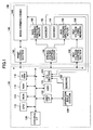
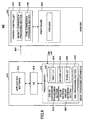
- FIG. 1 is a block diagram showing a hardware structure of an image processing apparatus 100 according to an embodiment of the present invention.
- the image processing apparatus 100 includes a control section 110 and an image forming section 140 whose operation is controlled by the control section 110.
- the control section 110 includes a CPU (central processing unit) 112, a ROM 114, a RAM 116, and an NVRAM 118.
- the CPU 112 controls the entire operations of the image processing apparatus 100.
- the ROM 114 stores application programs to be executed by the CPU 112 and data to be processed by the CPU 112.
- the RAM 116 supplies an execution space when the CPU 112 executes a program.
- the RAM 116 can be a storage unit for processing image data.
- the NVRAM 118 temporarily stores data for use in the RAM 116, and data to be stored for a long period of time.
- the image processing apparatus 100 receives a user input (instruction) from an operation input section 126 and sends the user input to a user I/F (interface) 120.
- a user I/F 120 receives the user input
- the user I/F 120 sends a command for executing the user instruction to the CPU 112.
- the control section 110 further includes an ASIC (application specific integrated circuit) 122 for executing image processes.
- the ASIC 122 applies the image processes to image data obtained from an application unit such as a scanner application unit and generates output image data to be printed out.
- the ASIC 122 also functions as a color conversion unit and as an output data generating unit which generates output data in a format such as PDL (page description language) of PostScript (trade mark).
- the control section 110 further includes an external I/F 130, and receives image data from an information processing apparatus, for example, a personal computer connected via the external I/F 130, and generates output data to be printed out by applying the image processes to the received image data at the ASIC 122.
- the external I/F 130 is not particularly limited; however, there are interfaces capable of data transmission such as Ethernet (trade mark), USB (universal serial bus), IEEE 1294, IEEE 802, X, a public telephone network, an ISDN (integrated services digital network), and so on.
- the external I/F 130 can be installed as a modem or a TA/DSU to be connected to the public telephone network or the ISDN.
- the image processing apparatus 100 can receive compressed data of facsimile, processes the received data, and generate output data.
- the control section 110 further includes an I/O (input/output) section 124.
- the I/O section 124 receives signals output from sensors 128 and a rotary encoder (described below) and feeds back the signals for control in the image processing apparatus 100.
- the image forming section 140 receives output data and control data from the control section 110 so that the output data from the control section 110 are to be printed out, operates the hardware in the image processing apparatus 100, and outputs the received data as a print document.
- the image forming section 140 includes an image forming engine 148 which uses an existing image forming process in, for example, one of an inkjet printer and an electrophotographic printer.
- the image forming section 140 further includes a print control section 142, a driving system control section 144, and a high voltage control section 146.
- the print control section 142 receives the data output from the control section 110 and controls a semiconductor laser (not shown), a polygon mirror (not shown), and so on corresponding to pixel bits included in the data output from the control section 110.
- the print control section 142 receives the data output from the control section 110 and drives nozzles of an inkjet head (not shown) by generating a driving pulse of the nozzles corresponding to the data output from the control section 110.
- the driving system control section 144 manages and drives of a paper carrying motor (not shown), a clutch (not shown), a separation claw (not shown), and so on for carrying paper for printing corresponding to an image forming process of the image forming engine 148.
- the driving system control section 144 generates driving pulses for a main scanning direction motor 150 and a sub scanning direction motor 156, moves the inkjet head in the main scanning direction, and supplies the paper for printing to the image forming section 140 by driving a not shown paper carrying motor.
- the paper is output to the outside of the image forming section 140 by driving the sub scanning direction motor 156, and the paper is supplied to a user as a printed document.
- An encoder 152 detects the number of rotations of the main scanning direction motor 150 and sends the detected result to the I/O section 124, and an encoder 154 detects the number of rotations of the sub scanning direction motor 156 and sends the detected result to the I/O section 124.
- a bias voltage generated by the high voltage control section 146 is applied to high voltage using members 158, for example, a charging roller (not shown), a transfer roller (not shown), and a carrying belt (not shown); and a latent image forming process and an image transferring process can be executed.
- members 158 for example, a charging roller (not shown), a transfer roller (not shown), and a carrying belt (not shown); and a latent image forming process and an image transferring process can be executed.
- the bias voltage generated by the high voltage control section 146 is applied to the transfer roller for carrying the paper on which the image is formed so that static electric charges are accumulated on the carrying belt.
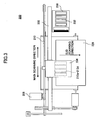
- FIG. 2 is a cut-away side view of an image processing apparatus 200 according to the embodiment of the present invention.
- the image processing apparatus 200 is an inkjet printer.
- the image processing apparatus 200 holds a carriage 206 that is slidable in the main scanning direction by a guide rod 202 and a guide rail 204.
- the guide rod 202 and the guide rail 204 function as guide members.
- the rotation of a main scanning direction motor 208 is transmitted to a driving member 214 formed of plural driving pulleys, and the carriage 206 is moved in the main scanning direction (orthogonal to the plane of the paper in FIG. 2 ).
- the carriage 206 includes four ink eject heads 212 which eject ink droplets of, for example, yellow (Y), cyan (C), magenta (M), and black (K), respectively.
- ink eject head 212 plural ink eject nozzles are arrayed in the direction orthogonal to the main scanning direction, and the ink droplet ejecting direction is the downward direction.
- the ink eject heads 212 any one of existing ink eject head types can be used in the image processing apparatus 200.
- the ink eject head 212 can include a piezoelectric actuator using a piezoelectric element, a thermal actuator which uses a phase change by liquid film boiling by using an electric-heat conversion element such as a heat generating resistor, a shape-memory alloy actuator which uses a metallic phase change due to a temperature change, or a static actuator which uses static electric charges, as a pressure generating unit for ejecting ink droplets.
- the image processing apparatus 200 can use plural ink eject heads 212 each of which ejects a single color or can use a single ink eject head 212 in which plural nozzles for ejecting corresponding plural colors are integrated.
- Sub tanks 214 are disposed in the carriage 206 and the sub tanks 214 supply corresponding color inks to the corresponding ink eject heads 212.
- the sub tank 214 stores ink in which a color material is dissolved or dispersed in liquid and the ink can be ejected on image receiving paper 228 such as high-quality paper or specially made paper.
- Image receiving paper 228 is stored in a paper feeding cassette 218, and is transported to a position of the ink eject heads 212 from a paper feeding section including a paper feeding roller 220 and a paper separation pad 222.
- the image receiving paper 228 is electrostatically adhered on a transport belt 224 and transported to the position of the ink eject heads 212.
- An image is formed on the image receiving paper 228 by ink from the ink eject head 212 and is output to a paper outputting tray 226.
- FIG. 3 is a plan view of a part of the image processing apparatus 200.
- the right and left direction is the main scanning direction, and as the ink eject heads 212, four ink eject head 212a through 212d for four colors are shown.
- the image processing apparatus 200 drives the ink eject head 212 (212a through 212d) based on image signals while reciprocally moving the carriage 206 in the arrow direction (the main scanning direction).
- the image receiving paper 228 is stopped during the reciprocal movement of the carriage 206, and one line of the image is recorded on the image receiving paper 228 by ejecting ink droplets onto the paper receiving paper 228.
- the image processing apparatus 200 detects a recording completion signal sent from the print control section 142 (see FIG. 1 ) or a signal showing that the end of the image receiving paper 228 reaches an image recording region, the image processing apparatus 200 stops the recording operation and outputs the image receiving paper 228 to the paper outputting tray 226 (see FIG. 2 ).
- the image processing apparatus 200 can include a duplex print function.
- the duplex print function when an image has been printed on a first surface of the image receiving paper 228, the image receiving paper 228 is transported to a duplex print unit by rotating transporting members in reverse with control of the driving system control section 144 (see FIG. 2 ) so that the sub scanning direction is reversed, and the image receiving paper 228 is reversed. After this, the image receiving paper 228 is transported to the position of the ink eject heads 212 by changing the paper transporting direction in the forward direction, and an image is printed on a second surface of the image receiving paper 228 by sending driving signals to the ink eject head 212.
- the image processing apparatus 200 moves the carriage 206 to the side of a maintain and recovery mechanism 230, caps nozzle surfaces of the ink eject heads 212, maintains the nozzle surfaces in a moistened condition, and prevents an ink eject defect caused by drying ink.
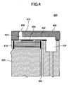
- FIG. 4 is a cut-away side view of the ink eject head 212 along a long length direction of a liquid chamber.
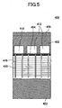
- FIG. 5 a cut-away side view of the ink eject head 212 along a short length direction (nozzle arraying direction) of the liquid chamber.
- FIGs. 4 and 5 as the ink eject head 212, an ink eject head 400 is shown. However, in the following, the ink eject head 212 is used in the description.
- the ink eject head 212 is formed by joining an ink flowing route plate 402, a vibration plate 404 formed on the lower surface of the ink flowing route plate 402, and a nozzle plate 406 formed on the upper surface of the ink flowing route plate 402.
- the ink flowing route plate 402 is formed by, for example, applying an anisotropic etching to a single-crystal silicon substrate.
- the vibration plate 404 is formed by a nickel electro-casting method.
- the above elements form a nozzle 408 for ejecting ink droplets, a nozzle connecting route 410 for connecting to the nozzle 408, and a liquid chamber 412 which is a pressure generating chamber.
- the ink eject head 212 includes a common liquid chamber 414 for supplying ink to the liquid chamber 412.
- the ink eject head 212 includes a stacked type piezoelectric element 416 and a base substrate 420 to which the stacked type piezoelectric element 416 is secured.
- the piezoelectric element 416 deforms the vibration plate 404 and functions to be a pressure generating unit (actuator unit) which applies pressure to ink in the liquid chamber 412.
- a signal cable 422 is connected to the piezoelectric element 416.
- the signal cable 422 supplies a driving signal from a nozzle driving circuit in the print control section 142 (see FIG. 2 ) to the piezoelectric element 416.
- the piezoelectric element 416 is driven corresponding to the signal supplied from the print control section 142.
- the plural liquid chambers 412 are arrayed and plural color ink droplets are ejected along the main scanning direction.
- plural supporting pillars 430 are disposed between the piezoelectric elements 416 for supporting the piezoelectric elements 416.
- a driving sequence of the ink eject head 212 is described.
- a voltage to be applied to the piezoelectric element 416 is decreased from a reference voltage, the piezoelectric element 416 contracts and the vibration plate 404 is lowered.
- the volume of the liquid chamber 412 is increased and ink flows into the liquid chamber 412.
- the piezoelectric element 416 expands in the stacked direction, and the vibration plate 404 is deformed in the direction of the nozzle 408.
- a partial pressure is applied to the ink in the liquid chamber 412, and the ink is ejected from the nozzle 408 as ink droplets.
- the vibration plate 404 When the voltage to be applied to the piezoelectric element 416 is returned to the reference voltage, the vibration plate 404 returns to an original position, the volume of the liquid chamber 412 is increased, and a suction (negative) pressure is generated. At this time, ink is supplied to the liquid chamber 412 from the common liquid chamber 414. The next time ink ejection is started after the vibration of the meniscus surface of the nozzle 408 is attenuated and becomes stable.
- FIG. 6 is a block diagram showing an image processing system 600 according to the embodiment of the present invention.
- an image processing apparatus 610 is shown.
- the image processing apparatus 610 is realized by installing a printer driver 616, which performs image processing in the embodiment of the present invention, in a personal computer, or a workstation.
- an image forming section 640 is an independent printer.
- the image forming section 640 (printer) converts image data transmitted from the image processing apparatus 610 into control signals by using a printer control language and outputs the signals from a print engine 644.
- the printer 640 receives the image data described in a format such as PDL (page description language) transmitted from the image processing apparatus 610 via a connection element 650 such as Ethernet, USB, IEEE 1394, IEEE 802, X, and so on.
- PDL page description language
- the image processing apparatus 610 processes, forms, and edits a lot of documents by using application software 612 which is installed as an application unit such as word processor software, image processing software, and spreadsheet software. Execution of the application software 612 is managed by an OS (operating system) 614, and the document can be output, stored, or read. A document formed by a user with the use of the application software 612 is sent to the printer driver 616 based on a user instruction.
- application software 612 which is installed as an application unit such as word processor software, image processing software, and spreadsheet software.
- Execution of the application software 612 is managed by an OS (operating system) 614, and the document can be output, stored, or read.
- a document formed by a user with the use of the application software 612 is sent to the printer driver 616 based on a user instruction.
- the printer driver 616 includes a color conversion processing section 618 which functions as a color conversion processing unit and a PDL processing section 630 which functions as an output data generating (forming) unit.
- the PDL processing section 630 forms output data of a format in PDL such as PostScript (trade mark).
- the color conversion processing section 618 performs a color conversion process to a CMY(K) system by using such as RGB, XYZ, CIE 1976L*a*b*, and HSV as an input color space coordinate.
- application software is formed by a personal computer, the color conversion is performed from a RGB system to the CMY(K) system.
- the color conversion to the CMY system is performed by CMM which uses a color conversion table 622 formed as a LUT (look up table).
- a color conversion table 622 formed as a LUT (look up table).
- a four-dimensional black (K) is introduced from a viewpoint of adjustment of a spectral characteristic of a color material and decrease of an amount of the color material.
- K four-dimensional black
- several methods are assumed; however, in any method, a CMY value is formed and a three-dimensional CMY system or a four-dimensional CMYK system is registered in the LUT. With this, any color conversion can be realized.
- the color conversion processing section 618 converts input color space coordinate data (in this specific case, RGB data) into CMY data.
- the printer driver 616 further includes a color material amount obtaining section 620.
- the color material amount obtaining section 620 obtains a color material using amount to be used corresponding to the input color space coordinate data in a color material using amount reducing mode, compares the obtained amount with a threshold value of the color material using amount, and controls the color material using amount in the color material using amount reducing mode.
- the color conversion table 622 includes a first LUT 624, a second LUT 626, and a third LUT 628.
- the first LUT 624 has an optimal color reproduction data structure and is used in color conversion in which input color space coordinate data such as RGB data are optimally reproduced in a normal mode not for reducing the color material.
- input color space coordinate data such as RGB data
- the input color space coordinate data are reproduced by using the entire color region reproduction range of the color material. That is, a default setting is established.
- the second LUT 626 is used when the user selects the color material using amount reducing mode.
- the color conversion processing section 618 refers to the second LUT 626, and performs the color conversion by using a color material using amount given by a correction function when a color material using amount given in a monochrome standard mode is made to be a reference.
- the third LUT 628 is used when the color conversion processing section 618 performs in a fixed coefficient mode by referring to the third LUT 628.
- the fixed coefficient mode is a color material using amount reducing mode which refers to a CMY value corresponding to a color material using amount formed by multiplying a color material using amount for a full color image by a fixed coefficient which is a positive value 1 or less.
- the fixed coefficient can be arbitrarily selected corresponding to a specific structure, for example, in a structure in which a CMY value is obtained by multiplying a coefficient by an input color space coordinate value, or in a structure in which a value is obtained by multiplying a coefficient by the obtained CMY value when the linearity of the mode is arbitrarily corrected.
- the first through third LUTs 624, 626 and 628 are loaded in a RAM and so on from an HDD when the image processing system 600 is started up, and are used by the color conversion processing section 618.
- the second and third LUTs 626 and 628 for the color material using amount reducing modes can be independently formed.
- the second and third LUTs 626 and 628 can be formed as an integrated unit.
- the printer driver 616 when the printer driver 616 is installed in a personal computer, the first through third LUTs 624, 626, and 628 have been formed beforehand by using a LUT forming device, for example, a workstation, and can be delivered to the personal computer together with a ROM or a program.
- a LUT forming device for example, a workstation
- the user of the personal computer stores the LUTs 624, 926, and 628 in an HDD.
- the printer driver 616 forms the LUTs 624, 626, and 628 as modules of image processing application software on demand based on the user setting.
- the image forming section (printer) 640 includes a printer controller 642 and the print engine 644.
- the printer controller 642 forms output data special for a printer and sends the output data to the print engine 644.
- the printer controller 642 correlates tone data after a ⁇ correction process to a predetermined dither pattern by using the density conversion processing section 646, and applies an area conversion to the tone data by using the tone conversion processing section 648.
- the print engine 644 has a structure similar to the structure of the image forming section 140 shown in FIG. 1 , and forms an image on image forming paper by using the output data with the use of an electrophotographic method or an inkjet method.
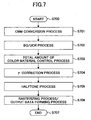
- FIG. 7 is a flowchart showing output data forming processes including a color conversion process according to the embodiment of the present invention.
- the processes shown in FIG. 7 are performed by the ASIC 122 shown in FIG. 1 , and are performed by the printer driver 616 shown in FIG. 6 .
- a CMM (color) conversion process is applied to image data based on a color material using mode selected by a user by using the LUT 624, 626, or 628 (S701).
- a BG/UCR process is applied to the image data for determining a black (K) amount and three-dimensional CMY data are converted into four-dimensional CMYK data (S702).
- a total amount of color material control process is applied to the CMYK data for controlling the total amount of the color materials (S703).
- a ⁇ correction process and a halftone process are applied to the CMYK data (S704 and S705).
- an identification value of a dither matrix corresponding to tone level data after the ⁇ correction process is selected and the image data are converted into area expression data.
- a rasterizing process, a font data identification process, and a paging and command adding process are applied to the image data and the output data are formed (S706).
- the above processes can be applied to the normal mode and the color material using amount reducing mode.
- the normal mode a full color image is output by using a color material amount in which the entire color region reproduction range of a printer can be expressed, and in the normal mode, the CMM conversion process (S701) is different from that in the color material using amount reducing mode.
- the color material using amount reducing mode the color material using amount is decreased.
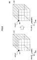
- FIG. 8 is a diagram showing a color conversion process using CMM according to the embodiment of the present invention.
- a document (image data) formed by application software is formed as input color space coordinate data independent from a printer, for example, as RGB data.
- the printer must print the document by using CMY(K) data of a subtractive color mixing system. Therefore, when the RGB data of the document are converted into CMY data or CMYK data dependent on the printer, a LUT has been prepared beforehand, and an RGB three-dimensional solid 810 is converted into a CMY three-dimensional solid 820 by using the LUT.
- FIG. 8 A most direct color conversion process from RGB data to CMY data is exemplified in FIG. 8 .
- the LUT is formed at sample points of color solids, and output color data n' (C,M,Y) 822 is obtained from input color data n (R,G,B) 812 by arbitrarily applying an interpolation process.
- the printer performs a printing output process in a four-dimensional color space of a CMKY system, the BG/UCR process is applied to the data, and printer specific data are converted from CMY data to C' M' Y' K' data.
- the image processing apparatus 100 selects the normal mode or the color material using amount reducing mode based on a user instruction, and performs a color conversion process corresponding to the selected mode.
- the normal mode means a print mode in which printing is performed by a color material using amount which optimally reproduces the entire color region reproduction range of the image forming section 140 or the printer 640.
- the color material using amount reducing mode means a print mode in which printing is performed by a color material using amount less than the color material using amount for optimal reproduction by considering reduction of print cost even if a reproducible color region of the image forming section 140 (640) is decreased.
- the color region reproduction range is reduced; however, the amount of consumed goods such as toners and ink is reduced, and color printing can be performed at a cost substantially equal to in monochrome print.
- a monochrome standard mode is a color material using amount reducing mode which uses CMY data to reproduce an image with a color material using amount when a monochrome halftone image is obtained by applying a NTSC conversion to input color space coordinate data.
- the second LUT 626 can be used when the color material using amount is reduced in the monochrome standard mode depending on hue and image data characteristics.
- the second LUT 626 can be also used in a color conversion in which the second LUT 626 is adjusted by using a correction function so as to control the color material using amount as the color material using amount in the monochrome standard mode is a reference when the color material using amount is more than a threshold value.
- the monochrome standard mode is defined to be a color output mode with a color material using amount in an "s"% (s is an integer 0 to 100) range with a "K” amount (black color material amount) as the reference to be output when a color image is converted into a monochrome image.
- the amount "K” to be output is obtained by Mathematical Formula (1) when a color image is converted into a monochrome image.
- the third LUT 628 is used for a color conversion of a fixed coefficient mode as a color material using amount reducing mode.
- the fixed amount mode is defined as a print mode in which a color material using amount when an input color space coordinate is to be output in a normal mode is multiplied by a fixed coefficient Fix (an integer of 0 to 100).
- a fixed coefficient Fix an integer of 0 to 100.
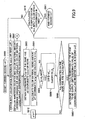
- FIG. 9 is a flowchart showing processes forming the second LUT 626.
- an input color space coordinate point (a, b, c) of the first LUT 624 is obtained (S901).
- a repetition counter "p" and a color material amount difference variable Diff are initialized and a color material using amount Dmono[m] of a CMY coordinate point corresponding to the coordinate point (a, b, c) is calculated (S902).
- the color material using amount Dmono[m] is calculated from (c ⁇ K ⁇ s) where "K” is obtained from Mathematical Formula (1) and "c” is a proportional constant to obtain the color material using amount of "K” given in the NTSC conversion in the monochrome standard mode, and the Dmono[m] is calculated to be a level value of the color material using amount Dcolor in the normal mode.
- the color material using amount Dmono[m] can be calculated by any method when the same relationship as that above is given.
- FIG. 9 the processes in the color conversion process are shown when the color material using amount is reduced in the monochrome standard mode; however, when the value of the Dmono[m] is given in a color material using amount range having a set threshold value or more by a correction function, a data structure can be established which can be commonly used within the fixed coefficient mode.
- the processes on and after S903 correspond to forming processes of the second LUT 626.
- the third LUT 628 to be used in the fixed coefficient mode is formed in processes shown in FIG. 11 connected to A point from S902.
- the initial value of the color material difference variable Diff is determined to be a value greater than the maximum color material difference.
- a coordinate point (e,f,g) is obtained from the first LUT 624 (S903)
- the coordinate point (e,f,g) has the same hue as that of the coordinate point (a,b,c) and its luminance L* is the luminance of the coordinate point (a,b,c) or more.
- the coordinates of a sample point having ⁇ Hue ⁇ ⁇ are obtained from sample points on the first LUT 624, and the obtained coordinate point is registered in a set variable or an array variable.
- ⁇ Hue is a hue difference between the coordinate point (a,b,c) and the coordinate point (e,f,g), and is given by ⁇ sqrt((a*) 2 + (b*) 2 ) ⁇ ; and " ⁇ " is a positive small decimal fraction.
- p is calculated (S904). Then
- OutCMY (h,i,j) p registered at the stage is determined to be an output CMY coordinate value of the coordinate point (a,b,c) and the determined CMY coordinate value is registered in a coordinate point (a,b,c) record of the second LUT 626 (S909).
- the input color space coordinate point and the CMY coordinate point which give a density of the monochrome standard mode are registered in the second LUT 626. Therefore, by the color conversion referred to the second LUT 626, the CMY value, which gives a color material using amount in the monochrome standard mode in which the luminance is high and the hue is the same, can be obtained from the input RGB coordinates.
- the BG/UCR process is applied to the obtained CMY value, four-dimensional color space data C,M, Y, K are formed, and output data are formed by the processes shown in FIG. 7 .
- the processes shown in FIG. 9 can be used in the color material using amount reducing mode.
- the color material using amount reducing mode uses both the fixed coefficient mode to be used near the predetermined threshold value and the monochrome standard mode which uses the second LUT 626 adjusted by a correction function.
- FIG. 10 is a diagram showing a second LUT forming processes.
- the processes are graphically shown. Similar to the first LUT 624 which is used in the normal mode, an input color space coordinates 1000 corresponding to a color space solid are registered in the second LUT 626. In addition, CMY coordinate values 1004 corresponding to the input color space coordinates 1000 are registered in the second LUT 626. When the second LUT 626 is compared with the first LUT 624, a low value of the color material using amount is substituted for the CMY value to be related to the input color space coordinates.
- the second LUT 626 can be formed by an LUT forming device independent from the image processing apparatus 100 (610), or can be formed by the image processing apparatus 100 (610) on the fly based on the user instruction.
- an RGB value of a sample point of the first LUT 626 is selected from the input color space coordinates 1000, and a CMY color space coordinate corresponding to the selected coordinates are obtained.
- the second LUT 626 includes a color material amount Dcolor to be used in the normal mode at the obtained CMY point, and color material using amount corresponding data 1002 which registers a color material using amount to be used in the monochrome standard mode. In the color material using amount corresponding data 1002, color material amount conversion fields 1006 and 1008 are registered corresponding to each tone level.
- a color material using amount Dmono [1] in the monochrome standard mode corresponding to the field 1008 is obtained.
- coordinate values whose hue is the same and whose luminance is higher than those in the coordinate values are listed up from the input color space coordinates 1000.
- a Dcolor[min] whose color material using difference Diff is a minimum value is obtained in the listed up sample points from the field 1006
- a CMY value in the first LUT 624 indexed to the Dcolor [min] is obtained, and the obtained CMY value is registered in the field of the CMY coordinate value 1004 as a target color space coordinate of the input color space coordinate corresponding to the second LUT 626.
- the second LUT 626 is formed.
- the second LUT 626 different from in the first LUT 624 in which the relationship between the RGB data and the CMY data is described, as shown by a dashed line in FIG. 10 , the RGB data are described in a relationship with the color difference minimum C'M'Y' data.
- the second LUT 626 is adjusted by using a correction function, since the value of Dmono[m] can be set to a using amount given from the monochrome normal using amount by the correction function, the second LUT 626 can be adjusted.
- the RGB data are converted into the CMY(K) data which can be used in a printing device.
- other data for example, Yuv data and XYZ data other than the RGB data can be converted into actually usable data in the printing device.
- the color materials are not limited to CMYK materials, and the present embodiment can be applied to special colors such as light cyan and light magenta.
- FIG. 11 is a flowchart showing processes forming the third LUT 628.
- the processes start from the connection point A in FIG. 9 .
- a fixed coefficient is multiplied by a color material using amount Dcolor of a coordinate value corresponding to a coordinate point (a,b,c) or a coordinate value (CMY) after the CMM conversion (S1101).
- CMY coordinate value having Dcolor[near] nearest to the color material using amount by which the fixed coefficient is multiplied and the obtained CMY coordinate value is registered by being related to the coordinate point (a,b,c) (S1102).
- the CMY coordinate point is registered in the third LUT 628 which gives a density in a relationship between the input color space coordinate point and the fixed coefficient mode.
- an interpolation calculation between the sample points can be performed by using the correction function used in the first LUT 624.
- a set of plural third LUTs 628 can be formed by changing the Fix value (fixed coefficient) with an interval of, for example, 10%.
- the Fix value fixed coefficient
- the set of the plural third LUTs 628 can be installed. Therefore, in this case, a user can select a color material using amount reducing mode having a different fixed coefficient from a print wizard of the image processing apparatus 100 (610).
- characteristic curves of the color material using amounts are calculated which are given by the second LUT 626 and the third LUT 628 related to the input color space coordinates.
- a difference between a color material using amount of the second LUT 626 after the intersection point and a total color material using amount of the second LUT 626 is minimized, and a difference between a color material using amount of the third LUT 628 before the intersection point and the total color material using amount of the second LUT 626 is minimized.
- a correction function is formed which determines that the color material using amount after the intersection point is to be smaller than the color material using amount in the monochrome standard mode, and a CMY value is obtained from the first LUT 624 in which the difference of the color material using amount given by the correction function and the hue difference are minimum values, and the second LUT 626 is adjusted.
- s% (a correction function value/a monochrome standard mode value) ⁇ 100 is given.
- the value in the second LUT 626 is adjusted near a threshold value which has been set beforehand by considering the color material using amount.
- the threshold value can be set in the color material using amount or in the tone level of the CMY of the image.
- FIG. 12 is a diagram showing the comparison example.
- observation data of color material using amount characteristics 1200 in the monochrome standard mode and the fixed coefficient mode are shown.
- a CMY hue and an RGB hue are shown on the paper surface, and the color material using amount is plotted as a distance from the center 1202. When the distance from the center 1202 is large, the color material using amount is increased.
- a line 1204 shows the color material using amount in the monochrome standard mode using an NTSC conversion, and a line 1206 shows the color material using amount in the fixed coefficient mode.
- the color material is substantially uniformly reduced in each hue.
- the color material is extremely reduced in the Y hue.
- the color material reducing effect is low in the B hue.
- a coefficient corresponding to a visual appreciation characteristic of a person is multiplied for the input RGB data, and the data is output as K data; therefore, the reducing amount in Y becomes great.
- the color material reducing amounts are different among the hues.
- the color material using amount can be reduced; however, the color material reducing amounts are largely different among the hues, and high image quality may not be obtained.
- the color material reducing amounts are not greatly different among the hues.
- FIG. 13 is a diagram showing output images formed by multiplying with different fixed coefficients for one image.
- (a) and (c) are examples in the embodiment of the present invention, and (b) is a comparative example.
- the output image after the halftone process becomes an image in which only dots are substantially recognized, and the image quality of the output image is remarkably lowered.
- the fixed coefficient is preferably in a range from 0.3 to 0.6.
- the fixed coefficient range to be selected is small; and in order that the image quality substantially equal to in monochrome printing is obtained, when the fixed coefficient is made to be small only in the fixed coefficient mode, the image quality cannot be high. That is, in order not to generate image degradation such as a highlight skip in the halftone process, in the fixed coefficient mode, a higher color material using amount than that in the monochrome standard mode is required. Consequently, a sufficient color material reducing effect is not obtained.
- the color material using amount can be reduced; however, when only one of the color material using amount reducing modes is used, the sufficiently high image quality may not be obtained.
- the color material using amount is minimized with the color material using amount in the monochrome printing as the reference, the following have been studied.
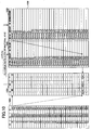
- FIG. 14 is a graph showing the color material using amount.
- the vertical axis shows the color material using amount (droplet amount) and the horizontal axis shows prints on patches in which hue and luminance are different from each other.
- the patches are arrayed in order of the color material using amount from low to high. That is, the left side corresponds to a highlight color side and the right side corresponds to a shadow color side.
- the same reference number as that shown in FIG. 12 is used. However, the contents of the reference number are different from those shown in FIG. 12 . That is, a line 1200 shows the normal mode, a line 1202 shows the monochrome standard mode, a line 1204 shows the fixed coefficient mode whose coefficient is 0.5, and a line 1206 shows the color material using amount reducing mode.
- a so-called medium color region connecting the highlight color and the shadow color is a most characterized region in a color image, and as shown in FIG. 13 , shading continuity and maintainability of dots of the color image greatly influence the psychological effect of users.
- light colors having a medium density are frequently used as the background of a table, and in many cases, each of the light colors may have a corresponding individual meaning.
- maintaining the image dots and contrast in the region from the highlight colors to the medium colors is very important for the psychological effect on users given from the color image.
- the contrast is increased while the image dots from the highlight colors to the medium colors are maintained in the color material using amount reducing mode, a bad psychological effect caused by the decrease of the color material using amount can be reduced.
- the color material using amount be increased with the color material using amount in the fixed coefficient mode as the reference rather than the color material using amount simply being increased with the color material using amount in the monochrome standard mode as the reference shown in FIGs. 12 and 14 .
- the decrease of the color material using amount affects not only the tone but also the hue; therefore, for example, the color material using amount in Y is extremely decreased, and scalability of a correction effect cannot be obtained by the image color data.
- the correction effect can be uniformly applied to each hue. Therefore, a bad influence on the color reproducibility of the medium colors, for example, tone balance being degraded between hues, can be minimized.
- the fixed coefficient when the fixed coefficient is determined to be 30% to 60%, as shown in FIG. 13 , a recognizable image can be obtained.
- the fixed coefficient is determined to be 60% or more, in some cases, it may be difficult for the color material using amount to be decreased to the color material using amount of the monochrome standard.
- the lower limit is not particularly limited when the ability to recognize the image is obtained.
- the fixed coefficient when the image quality is considered, the fixed coefficient must be determined to be a value so that the color material using amount becomes the amount in the monochrome standard mode or more. Therefore, the range of the fixed coefficient can be obtained by Mathematical Formula (2). [Mathematical Formula (2)] Value of Color Material Using Amount to be given in Monochrome standard mode or More ⁇ Fixed Coefficient ⁇ 0.6
- the color material using amount In order for the color material using amount to be substantially near the amount in the monochrome standard mode while maintaining the image quality, the color material using amount must be a value greater than the amount in the monochrome standard mode in the range between the highlight colors and the medium colors; consequently, the color material using amount at the shadow color side must be decreased. In this case, the color material using amount is decreased at the shadow color side where it exceeds a predetermined threshold value from the color material using amount in the monochrome standard mode. That is, the color material using amount is managed to be switched.
- the color material using amount is increased between the highlight colors and the medium colors, and the color material using amount is decreased at the shadow color side so that the color material using amount becomes a nearest amount in the monochrome standard mode.
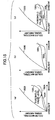
- FIG. 15 is a diagram showing a color material using amount reducing process according to the embodiment of the present invention.
- a line 1500 shows the color material, using amount at a full color image output
- a line 1502 shows the color material using amount in the monochrome standard mode
- a line 1504 shows the color material using amount in the fixed coefficient mode.
- the color material using amount is greater than that in the monochrome standard mode; consequently, the image quality is higher than that in the monochrome standard mode in the range.
- the fixed coefficient mode is used in the range between the highlight color and the medium colors, the degradation of the image quality can be minimized; however, the color material using amount cannot be sufficiently decreased. Therefore, in the embodiment of the present invention, a switching process is applied to the range between the highlight colors and the medium colors.
- each of the intersection point and the predetermined threshold value is referred to as a threshold value or a threshold value level.
- a threshold value level is shown by an arrow.
- the threshold value is determined for the color material using amount; however, the threshold value can be determined for the hue and the input color space coordinate point when the hue relates to the color material using amount. In this case, the threshold value is determined for each hue.
- FIG. 15 shows a case in which the characteristic curve described in FIG. 14 has an intersection point at a position between the highlight colors and the shadow colors
- (b) and (c) show cases in which the intersection point does not exist at a position between the highlight colors and the shadow colors.
- the interpolation function 1506 is formed from the threshold value of the color material using amount so as to smoothly connect to the line 1504 of the fixed coefficient mode.
- the interpolation function 1506 commonly uses the point with the characteristic curve of the fixed coefficient mode and determines coefficients and function type of the interpolation function 1506 and a spline function so that an absolute difference
- the interpolation function 1506 is determined so that an input color space coordinate value of a sample point in the second LUT 626 are converted into CMY data in which a color difference of the color material using amount given by the interpolation function 1506 is minimized. Then the interpolation function 1506 is used to adjust the second LUT 626 of the monochrome standard mode by using the color material using amount given by the interpolation function 1506.
- a threshold value can be determined for an input color space coordinate value or a hue value of HSV or sqrt ⁇ (a*) 2 +(b*) 2 ⁇ .
- the color material reducing process is not applied to a character object and a line art object of color images. This process can be suitably applied when output data are formed by separating raster data from font data.
- a different color material reducing process can be applied to the character object and the line art object from a color material reducing process to be applied to raster data.
- the color material reducing effect may be slightly lowered; however, the color material using amount can be reduced in all the image data while maintaining recognition ability of the character object and the line art object.
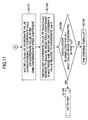
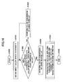
- FIG. 16 is a flowchart showing a color material using amount reducing process in a color material using amount reducing mode according to the embodiment of the present invention.
- an input color space coordinate is obtained (S1601).
- the threshold value can be arbitrarily determined by a user, or can be an intersection point between characteristic curves between fixed coefficient mode and the monochrome standard mode when the intersection point exists.
- the color conversion is performed by using the second LUT 626 in which the color material using amount is reduced (S1604).
- data of the monochrome standard mode are not stored, and CMY data corresponding to the color material using amount given by the interpolation function are stored.
- the color conversion is performed by using the third LUT 628 in which the color material using amount is reduced in the fixed coefficient mode (S1603).
- the output data can be printed by the color material using amount nearest to the monochrome standard mode in the shadow colors while maintaining contrast in the highlight colors, and the tradeoff between the image quality and the color material using amount can be lowered.
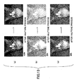
- FIG. 17 is a diagram showing the color material using amounts in the color material using amount reducing mode, the fixed coefficient mode, and the monochrome standard mode.
- the color material using amounts are shown with the color material using mount in the monochrome standard mode as the reference in several images.
- the left side shows the amount in the monochrome standard mode
- the center shows the amount in the fixed coefficient mode
- the right side shows the amount in the color material using amount reducing mode.
- the color material using amounts in the fixed coefficient mode are generally smaller than the amounts in the monochrome standard mode.
- the reason can be estimated from the following.
- the color material using amount is greater than the amount in the monochrome standard mode in the highlight color side, since a fixed coefficient is multiplied in the shadow color side, the total color material using amount is reduced as a integration value.
- the color material using amount is reduced by nearly 40%; therefore, it is understandable that high image quality may not be obtained only in the fixed coefficient mode.
- the color material using amount in the color material using amount reducing mode is substantially equal to the amount in the monochrome standard mode in the range ⁇ 10%, and substantially the same amount as in the monochrome standard mode can be obtained in the color material using amount reducing mode in the present embodiment.
- the color material using amount reducing mode in the present embodiment is compared with the cases in which the color material using amount is reduced by using the monochrome standard mode or the fixed coefficient mode, the color material reducing amount is stable; consequently, the color material using amount can be reduced while maintaining original image quality.
- the color conversion is performed when the fixed coefficient mode is applied from the highlight colors to the medium colors and the monochrome standard mode given by the interpolation function is applied to the shadow colors.
- the color conversion can be performed in which the monochrome standard mode is applied to from the highlight colors to the medium colors including hues and luminance and the fixed coefficient mode is applied to the shadow colors, in the special colors including CMYK data.
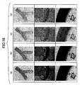
- FIG. 18 is a diagram showing printed images by a full color mode, the monochrome standard mode, the fixed coefficient mode, and the color material using amount reducing mode in the present invention.
- (a) shows printed images by the full color mode
- (b) shows printed images by the monochrome standard mode
- (c) shows printed images by the fixed coefficient mode
- (d) shows printed images by the color material using amount reducing mode in the present invention.
- color information is does not appear.
- FIG. 18(c) the shadow colors become remarkably lighter by a value of the fixed coefficient than in the full color mode.
- the contrast in the range from the highlight colors to the medium colors is increased, since the color material using amount in the shadow colors can be reduced greater than that in the fixed coefficient mode when compared with the fixed coefficient mode; the color material using amount from the highlight colors to the medium colors can be increased; and the psychological effect of the color material using amount reducing mode becomes substantially near that of the full color mode.
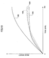
- FIG. 19 is a diagram showing tone reproducibility characteristics according to the embodiment of the present invention.
- the vertical axis shows the image density (reflection density) and the horizontal axis shows the tone level, in 8-bit resolution.
- a line 1900 shows the characteristics in the full color mode
- a line 1902 shows the characteristic in the monochrome standard mode using NTSC conversion
- a line 1904 shows the characteristics in the fixed coefficient mode
- a line 1906 shows the characteristics in the color material using amount reducing mode in the present invention.
- the image densities in the monochrome standard mode, the fixed coefficient mode, and the color material using amount reducing mode in the present invention are lower than the image density in the full color mode at the same tone level due to the reduction of the color material using amount.
- the amount to be applied is restricted, and the contrast to be maintained from the highlight colors to the medium colors is restricted.
- the color material using amount at the shadow side can be reduced by using the interpolation function so that the color material using amount at the range from the highlight colors to the medium colors is increased. Therefore, the total color material using amount from the highlight color side to the shadow color side, that is, the integrated color material using amount, can be almost the same amount as in the monochrome standard mode.
- the image is formed with higher contrast than in the fixed coefficient mode; therefore, the color image can be approximated to the full color image in the psychological effect.
- the color material using amount reducing mode according to the present embodiment can be installed in the ASIC 122 of the image processing apparatus 100.
- the color material using amount reducing mode according to the present embodiment can be installed in a printer driver of an information processing apparatus such as a personal computer and a workstation.
- the color material using amount reducing mode according to the present embodiment can be installed in a CMM conversion process, and can be installed in a hue correction LUT for reducing the color material using amount as a module.
- the module can be a preprocess module or a post process module of the BG/UCR process.
- a correction LUT or a correction equation can be executed on the fly in real time when a user inputs a target color material using amount (s%) and a fixed coefficient to be reference from a control panel or a control program.
- a fixed coefficient can be selected form predetermined fixed coefficients.
- the LUTs 624, 626, and 628 for reducing the color material using amount, dither patterns for the halftone process, and the interpolation function can be called up from a program as software; or can be stored in a ROM or a RAM corresponding to an image processing speed or CPU throughput.
- the above elements can be installed in a recording apparatus which processes from an image process to a print process as a standalone apparatus and in a recording system which processes from the image process to the print process by combining plural devices as application software.
- Programs for executing the color material using amount reducing process according to the present invention by using the LUTs and the correction functions are created in a legacy programming language such Assembler or C, or an object oriented programming language such as C++ or JAVA.
- the programs can be delivered by being installed in a computer-readable storing medium such as a CD-ROM or a DVD.
- the programs can be delivered via a network such as the Internet by using a file transfer protocol such as HTTP or FTP.
- the color material using amount reducing process according to the embodiment of the present invention can be applied to an image forming apparatus which uses a recording system such as an electrophotographic system, or a thermal transfer recording system, in addition to the inkjet system.
- a recording system such as an electrophotographic system, or a thermal transfer recording system, in addition to the inkjet system.
- printing cost including a color material using amount and color material cost
- a color material using amount and color material cost is reduced with user understandable values as a reference; that is, with the color material using amount and the color material cost in the monochrome print mode as the reference.
- lowering the psychological effect such as color invisibility caused by reduction of the color material using amount can be restrained. With this, the reduction of the color material using amount and the prevention of lowering the psychological effect can be achieve.
Description
- The present invention generally relates to an image processing apparatus, an image processing method, and a computer-readable recording medium storing an image processing program in which an image is formed by reducing a color region.
- Recently, plural electrophotographic copying apparatuses and plural printers have been installed in one office corresponding to wide availability of personal computers. Therefore, when plural image processing apparatus are installed in an office, costs of the image processing apparatuses have been greatly studied in addition to the study of image quality of the image processing apparatuses.
- When an image is formed, a monochrome image and a color image can be formed. When the monochrome image is formed, only one color material black (K) is required in either a laser scanning system or an inkjet system. On the other hand, when a color image is formed, generally, the color image is reproduced by using four color materials cyan (C), magenta(M), yellow (Y), and black (K) so that black reproducibility of the image is increased and amounts of the other color materials are reduced. In addition, when a user requests, five or more color materials including a special color material other than the CMYK materials are used.
- When a color image is formed, not only may each color material be used alone, but also hue, luminance, and so on must be expressed by mixing the color materials by superposing different color material images. Therefore, in some cases, the cost of forming a color image is several times the cost of forming a monochrome image.
- In order to decrease the cost of forming the color image, several studies have been performed. Generally, a color material using amount decreasing mode for decreasing a using amount of a color material, which is referred to as an economode or an ink reducing mode, is installed in an image processing apparatus.
- For example, in
Patent Document 1, a thinning out process is applied to image data by using a specific pattern, and the actual using amount of color materials is decreased. InPatent Document 2, the number of tones is decreased from input data with a predetermined ratio, components at a shadow side using a large amount of the color materials are decreased, and the total amount of the color materials is decreased. InPatent Document 3, a CMM (color matching method) is used and the amount of the color material is finely adjusted. - The method, in which the amount of the color materials is decreased by using CMM, is described in
Patent Documents - In
Patent Documents Patent Document 5, a different tone process is applied to the color materials whose luminances are different from each other in highlight and shadow by using CMM. InPatent Documents 4 through 6, when the amount of the color materials is decreased, a color region to be reproduced by image forming is decreased; however, and minimizing degradation of the color reproducibility caused by the decrease of the color region is not an objective. - That is, in
Patent Documents 1 through 6, the amount of the color material is decreased or the color reproducibility in highlight and shadow is increased by using CMM. The amount of the color material to be decreased while reproducing an image in high definition and minimizing the degradation of the image quality caused by the decrease of the color material are not described. Specifically, when the amount of the color material is decreased so as not be high cost, the reproduced image is blurred, and image impression and psychological effect to be originally obtained from the color image are decreased. Consequently, cost and image quality to be satisfied by a user cannot be obtained. - [Patent Document 1] Japanese Unexamined Patent Publication No.
2006-270927 - [Patent Document 2] Japanese Unexamined Patent Publication No.
H09-216419 - [Patent Document 3] Japanese Unexamined Patent Publication No.
2004-80266 - [Patent Document 4] Japanese Unexamined Patent Publication No.
2006-68982 - [Patent Document 5]
PCT International Patent Application No. WOA 2003-043306 - [Patent Document 6] Japanese Unexamined Patent Publication No.
2007-235661 - In an embodiment of the present invention, there is provided an image processing apparatus, an image processing method, and a computer-readable recording medium storing an image processing program in which an amount of a color material can be reduced while minimizing the psychological and physical influence on a user by the reduction of a color region caused by the reduction of the amount of the color material.
- To achieve one or more of these and other advantages, according to one aspect of the present invention, there is provided an image processing apparatus which performs a color conversion of image data. The image processing apparatus includes an application unit which obtains the image data, a color conversion unit which obtains at least CMY data from input color space coordinates of input color space coordinate data of the image data, and an output data generating unit which generates output data by forming CMYK data with the use of an output result of the color conversion unit. The color conversion unit includes an optimum color reproduction data structure which obtains at least the CMY data for obtaining a full color image optimally reproduced from the input color space coordinate data, and a color material using amount reducing data structure which obtains at least the CMY data in which the color material using amount is increased from a reference value for a hue of an output image that gives a large psychological effect and the color material using amount is decreased from the reference value for a hue of the output image that gives a small psychological effect so that the color material using amount of the input color space coordinate data is reduced by using the reference value.
- According to an embodiment of the present invention, a color material using amount reducing mode is installed in an image processing apparatus so that a color material cost at color printing becomes substantially near a cost at monochrome printing as much as possible with the material cost at the monochrome printing as the reference. In addition, the color material using amount is reduced by considering image quality of an output image and the reducing amount is different between hues. Therefore, the degradation of the image quality can be psychologically minimized.
- The features and advantages of the present invention will become more apparent from the following detailed description of a preferred embodiment given with reference to the accompanying drawings.
-
-
FIG. 1 is a block diagram showing a hardware structure of an image processing apparatus according to an embodiment of the present invention; -
FIG. 2 is a cut-away side view of another image processing apparatus according to the embodiment of the present invention; -
FIG. 3 is a plan view of a part of the image processing apparatus shown inFIG. 2 ; -
FIG. 4 is a cut-away side view of an ink eject head along a long length direction of a liquid chamber according to the embodiment of the present invention; -
FIG. 5 a cut-away side view of the ink eject head along a short length direction of the liquid chamber shown inFIG. 4 ; -
FIG. 6 is a block diagram showing an image processing system according to the embodiment of the present invention; -
FIG. 7 is a flowchart showing output data forming processes including a color conversion process according to the embodiment of the present invention; -
FIG. 8 is a diagram showing a color conversion process using CMM according to the embodiment of the present invention; -
FIG. 9 is a flowchart showing processes forming a second LUT shown inFIG.6 ; -
FIG. 10 is a diagram showing processes forming the second LUT shown inFIG. 6 ; -
FIG. 11 is a flowchart showing processes forming a third LUT shown inFIG. 6 ; -
FIG. 12 is a diagram of an a comparison example showing color material using amounts in different modes; -
FIG. 13 is a diagram showing output images formed by multiplying with different fixed coefficients for one image according to the embodiment of the present invention; -
FIG. 14 is a graph showing the color material using amounts in modes according to the embodiment of the present invention; -
FIG. 15 is a diagram showing a color material using amount reducing process according to the embodiment of the present invention; -
FIG. 16 is a flowchart showing the color material using amount reducing process in a color material using amount reducing mode according to the embodiment of the present invention; -
FIG. 17 is a diagram showing the color material using amounts in the color material using amount reducing mode, a fixed coefficient mode, and a monochrome standard mode; -
FIG. 18 is a diagram showing printed images by a full color mode, the monochrome standard mode, the fixed coefficient mode, and the color material using amount reducing mode; and -
FIG. 19 is a diagram showing tone reproducibility characteristics according to the embodiment of the present invention. - Referring to the drawings, an embodiment of the present invention is described in detail.
-
FIG. 1 is a block diagram showing a hardware structure of animage processing apparatus 100 according to an embodiment of the present invention. Theimage processing apparatus 100 includes acontrol section 110 and animage forming section 140 whose operation is controlled by thecontrol section 110. Thecontrol section 110 includes a CPU (central processing unit) 112, aROM 114, aRAM 116, and anNVRAM 118. TheCPU 112 controls the entire operations of theimage processing apparatus 100. TheROM 114 stores application programs to be executed by theCPU 112 and data to be processed by theCPU 112. TheRAM 116 supplies an execution space when theCPU 112 executes a program. In addition, theRAM 116 can be a storage unit for processing image data. TheNVRAM 118 temporarily stores data for use in theRAM 116, and data to be stored for a long period of time. - The
image processing apparatus 100 receives a user input (instruction) from anoperation input section 126 and sends the user input to a user I/F (interface) 120. When the user I/F 120 receives the user input, the user I/F 120 sends a command for executing the user instruction to theCPU 112. Thecontrol section 110 further includes an ASIC (application specific integrated circuit) 122 for executing image processes. TheASIC 122 applies the image processes to image data obtained from an application unit such as a scanner application unit and generates output image data to be printed out. TheASIC 122 also functions as a color conversion unit and as an output data generating unit which generates output data in a format such as PDL (page description language) of PostScript (trade mark). - The
control section 110 further includes an external I/F 130, and receives image data from an information processing apparatus, for example, a personal computer connected via the external I/F 130, and generates output data to be printed out by applying the image processes to the received image data at theASIC 122. The external I/F 130 is not particularly limited; however, there are interfaces capable of data transmission such as Ethernet (trade mark), USB (universal serial bus), IEEE 1294, IEEE 802, X, a public telephone network, an ISDN (integrated services digital network), and so on. - When the
image processing apparatus 100 is used as a standalone apparatus, for example, in which various applications can be processed, the external I/F 130 can be installed as a modem or a TA/DSU to be connected to the public telephone network or the ISDN. Theimage processing apparatus 100 can receive compressed data of facsimile, processes the received data, and generate output data. Thecontrol section 110 further includes an I/O (input/output)section 124. The I/O section 124 receives signals output fromsensors 128 and a rotary encoder (described below) and feeds back the signals for control in theimage processing apparatus 100. - The
image forming section 140 receives output data and control data from thecontrol section 110 so that the output data from thecontrol section 110 are to be printed out, operates the hardware in theimage processing apparatus 100, and outputs the received data as a print document. Theimage forming section 140 includes animage forming engine 148 which uses an existing image forming process in, for example, one of an inkjet printer and an electrophotographic printer. - The
image forming section 140 further includes aprint control section 142, a drivingsystem control section 144, and a highvoltage control section 146. When theimage forming section 140 uses an electrophotographic system, theprint control section 142 receives the data output from thecontrol section 110 and controls a semiconductor laser (not shown), a polygon mirror (not shown), and so on corresponding to pixel bits included in the data output from thecontrol section 110. When theimage forming section 140 uses an inkjet system, theprint control section 142 receives the data output from thecontrol section 110 and drives nozzles of an inkjet head (not shown) by generating a driving pulse of the nozzles corresponding to the data output from thecontrol section 110. - The driving
system control section 144 manages and drives of a paper carrying motor (not shown), a clutch (not shown), a separation claw (not shown), and so on for carrying paper for printing corresponding to an image forming process of theimage forming engine 148. The drivingsystem control section 144 generates driving pulses for a mainscanning direction motor 150 and a subscanning direction motor 156, moves the inkjet head in the main scanning direction, and supplies the paper for printing to theimage forming section 140 by driving a not shown paper carrying motor. When an image is printed on the paper, the paper is output to the outside of theimage forming section 140 by driving the subscanning direction motor 156, and the paper is supplied to a user as a printed document. Anencoder 152 detects the number of rotations of the mainscanning direction motor 150 and sends the detected result to the I/O section 124, and anencoder 154 detects the number of rotations of the subscanning direction motor 156 and sends the detected result to the I/O section 124. - When the
image processing apparatus 100 forms an image by using an electrophotographic system, a bias voltage generated by the highvoltage control section 146 is applied to highvoltage using members 158, for example, a charging roller (not shown), a transfer roller (not shown), and a carrying belt (not shown); and a latent image forming process and an image transferring process can be executed. When theimage processing apparatus 100 forms an image by using an inkjet system (printer), the bias voltage generated by the highvoltage control section 146 is applied to the transfer roller for carrying the paper on which the image is formed so that static electric charges are accumulated on the carrying belt. -
FIG. 2 is a cut-away side view of animage processing apparatus 200 according to the embodiment of the present invention. In the present embodiment, theimage processing apparatus 200 is an inkjet printer. Theimage processing apparatus 200 holds acarriage 206 that is slidable in the main scanning direction by aguide rod 202 and aguide rail 204. Theguide rod 202 and theguide rail 204 function as guide members. The rotation of a mainscanning direction motor 208 is transmitted to a drivingmember 214 formed of plural driving pulleys, and thecarriage 206 is moved in the main scanning direction (orthogonal to the plane of the paper inFIG. 2 ). - The
carriage 206 includes four ink eject heads 212 which eject ink droplets of, for example, yellow (Y), cyan (C), magenta (M), and black (K), respectively. In theink eject head 212, plural ink eject nozzles are arrayed in the direction orthogonal to the main scanning direction, and the ink droplet ejecting direction is the downward direction. - As the ink eject heads 212, any one of existing ink eject head types can be used in the
image processing apparatus 200. For example, theink eject head 212 can include a piezoelectric actuator using a piezoelectric element, a thermal actuator which uses a phase change by liquid film boiling by using an electric-heat conversion element such as a heat generating resistor, a shape-memory alloy actuator which uses a metallic phase change due to a temperature change, or a static actuator which uses static electric charges, as a pressure generating unit for ejecting ink droplets. In addition, theimage processing apparatus 200 can use plural ink eject heads 212 each of which ejects a single color or can use a singleink eject head 212 in which plural nozzles for ejecting corresponding plural colors are integrated. -
Sub tanks 214 are disposed in thecarriage 206 and thesub tanks 214 supply corresponding color inks to the corresponding ink eject heads 212. Thesub tank 214 stores ink in which a color material is dissolved or dispersed in liquid and the ink can be ejected onimage receiving paper 228 such as high-quality paper or specially made paper. -
Image receiving paper 228 is stored in apaper feeding cassette 218, and is transported to a position of the ink eject heads 212 from a paper feeding section including apaper feeding roller 220 and apaper separation pad 222. Theimage receiving paper 228 is electrostatically adhered on atransport belt 224 and transported to the position of the ink eject heads 212. An image is formed on theimage receiving paper 228 by ink from theink eject head 212 and is output to apaper outputting tray 226. -
FIG. 3 is a plan view of a part of theimage processing apparatus 200. InFIG. 3 , the right and left direction is the main scanning direction, and as the ink eject heads 212, four ink eject head 212a through 212d for four colors are shown. Theimage processing apparatus 200 drives the ink eject head 212 (212a through 212d) based on image signals while reciprocally moving thecarriage 206 in the arrow direction (the main scanning direction). In an image forming process, theimage receiving paper 228 is stopped during the reciprocal movement of thecarriage 206, and one line of the image is recorded on theimage receiving paper 228 by ejecting ink droplets onto thepaper receiving paper 228. Then theimage receiving paper 228 is transported by a predetermined amount, and the next line of the image is printed on theimage receiving paper 228. When theimage processing apparatus 200 detects a recording completion signal sent from the print control section 142 (seeFIG. 1 ) or a signal showing that the end of theimage receiving paper 228 reaches an image recording region, theimage processing apparatus 200 stops the recording operation and outputs theimage receiving paper 228 to the paper outputting tray 226 (seeFIG. 2 ). - The
image processing apparatus 200 can include a duplex print function. In a case where the duplex print function is performed, when an image has been printed on a first surface of theimage receiving paper 228, theimage receiving paper 228 is transported to a duplex print unit by rotating transporting members in reverse with control of the driving system control section 144 (seeFIG. 2 ) so that the sub scanning direction is reversed, and theimage receiving paper 228 is reversed. After this, theimage receiving paper 228 is transported to the position of the ink eject heads 212 by changing the paper transporting direction in the forward direction, and an image is printed on a second surface of theimage receiving paper 228 by sending driving signals to theink eject head 212. - During a printing standby period, the
image processing apparatus 200 moves thecarriage 206 to the side of a maintain andrecovery mechanism 230, caps nozzle surfaces of the ink eject heads 212, maintains the nozzle surfaces in a moistened condition, and prevents an ink eject defect caused by drying ink. -
FIG. 4 is a cut-away side view of theink eject head 212 along a long length direction of a liquid chamber.FIG. 5 a cut-away side view of theink eject head 212 along a short length direction (nozzle arraying direction) of the liquid chamber. - In
FIGs. 4 and5 , as theink eject head 212, anink eject head 400 is shown. However, in the following, theink eject head 212 is used in the description. - The
ink eject head 212 is formed by joining an ink flowingroute plate 402, avibration plate 404 formed on the lower surface of the ink flowingroute plate 402, and anozzle plate 406 formed on the upper surface of the ink flowingroute plate 402. The ink flowingroute plate 402 is formed by, for example, applying an anisotropic etching to a single-crystal silicon substrate. Thevibration plate 404 is formed by a nickel electro-casting method. The above elements form anozzle 408 for ejecting ink droplets, anozzle connecting route 410 for connecting to thenozzle 408, and aliquid chamber 412 which is a pressure generating chamber. In addition, theink eject head 212 includes acommon liquid chamber 414 for supplying ink to theliquid chamber 412. - In the present embodiment, as shown in
FIG. 4 , theink eject head 212 includes a stacked typepiezoelectric element 416 and abase substrate 420 to which the stacked typepiezoelectric element 416 is secured. Thepiezoelectric element 416 deforms thevibration plate 404 and functions to be a pressure generating unit (actuator unit) which applies pressure to ink in theliquid chamber 412. In addition, asignal cable 422 is connected to thepiezoelectric element 416. Thesignal cable 422 supplies a driving signal from a nozzle driving circuit in the print control section 142 (seeFIG. 2 ) to thepiezoelectric element 416. Thepiezoelectric element 416 is driven corresponding to the signal supplied from theprint control section 142. - In addition, as shown in
FIG. 5 , the pluralliquid chambers 412 are arrayed and plural color ink droplets are ejected along the main scanning direction. In addition, plural supportingpillars 430 are disposed between thepiezoelectric elements 416 for supporting thepiezoelectric elements 416. - Referring to
FIGs. 4 and5 , a driving sequence of theink eject head 212 is described. When a voltage to be applied to thepiezoelectric element 416 is decreased from a reference voltage, thepiezoelectric element 416 contracts and thevibration plate 404 is lowered. At this time, the volume of theliquid chamber 412 is increased and ink flows into theliquid chamber 412. After this, when the voltage to be applied to thepiezoelectric element 416 is increased, thepiezoelectric element 416 expands in the stacked direction, and thevibration plate 404 is deformed in the direction of thenozzle 408. By the contraction of theliquid chamber 412, a partial pressure is applied to the ink in theliquid chamber 412, and the ink is ejected from thenozzle 408 as ink droplets. - When the voltage to be applied to the
piezoelectric element 416 is returned to the reference voltage, thevibration plate 404 returns to an original position, the volume of theliquid chamber 412 is increased, and a suction (negative) pressure is generated. At this time, ink is supplied to theliquid chamber 412 from thecommon liquid chamber 414. The next time ink ejection is started after the vibration of the meniscus surface of thenozzle 408 is attenuated and becomes stable. -
FIG. 6 is a block diagram showing animage processing system 600 according to the embodiment of the present invention. InFIG. 6 , animage processing apparatus 610 is shown. Theimage processing apparatus 610 is realized by installing aprinter driver 616, which performs image processing in the embodiment of the present invention, in a personal computer, or a workstation. In addition, inFIG. 6 , animage forming section 640 is an independent printer. The image forming section 640 (printer) converts image data transmitted from theimage processing apparatus 610 into control signals by using a printer control language and outputs the signals from aprint engine 644. Theprinter 640 receives the image data described in a format such as PDL (page description language) transmitted from theimage processing apparatus 610 via aconnection element 650 such as Ethernet, USB, IEEE 1394, IEEE 802, X, and so on. - The
image processing apparatus 610 processes, forms, and edits a lot of documents by usingapplication software 612 which is installed as an application unit such as word processor software, image processing software, and spreadsheet software. Execution of theapplication software 612 is managed by an OS (operating system) 614, and the document can be output, stored, or read. A document formed by a user with the use of theapplication software 612 is sent to theprinter driver 616 based on a user instruction. - When the document includes image data, the
printer driver 616 includes a colorconversion processing section 618 which functions as a color conversion processing unit and aPDL processing section 630 which functions as an output data generating (forming) unit. ThePDL processing section 630 forms output data of a format in PDL such as PostScript (trade mark). The colorconversion processing section 618 performs a color conversion process to a CMY(K) system by using such as RGB, XYZ, CIE 1976L*a*b*, and HSV as an input color space coordinate. When application software is formed by a personal computer, the color conversion is performed from a RGB system to the CMY(K) system. - The color conversion to the CMY system is performed by CMM which uses a color conversion table 622 formed as a LUT (look up table). In general, in a color reproduction process using a subtractive color mixing method, a four-dimensional black (K) is introduced from a viewpoint of adjustment of a spectral characteristic of a color material and decrease of an amount of the color material. As the introducing method of the four-dimensional black, several methods are assumed; however, in any method, a CMY value is formed and a three-dimensional CMY system or a four-dimensional CMYK system is registered in the LUT. With this, any color conversion can be realized.
- The color
conversion processing section 618 converts input color space coordinate data (in this specific case, RGB data) into CMY data. Theprinter driver 616 further includes a color materialamount obtaining section 620. The color materialamount obtaining section 620 obtains a color material using amount to be used corresponding to the input color space coordinate data in a color material using amount reducing mode, compares the obtained amount with a threshold value of the color material using amount, and controls the color material using amount in the color material using amount reducing mode. - The color conversion table 622 includes a
first LUT 624, asecond LUT 626, and athird LUT 628. Thefirst LUT 624 has an optimal color reproduction data structure and is used in color conversion in which input color space coordinate data such as RGB data are optimally reproduced in a normal mode not for reducing the color material. In the optimal reproduction of the input color space coordinate data, the input color space coordinate data are reproduced by using the entire color region reproduction range of the color material. That is, a default setting is established. - The
second LUT 626 is used when the user selects the color material using amount reducing mode. In this case, the colorconversion processing section 618 refers to thesecond LUT 626, and performs the color conversion by using a color material using amount given by a correction function when a color material using amount given in a monochrome standard mode is made to be a reference. - The
third LUT 628 is used when the colorconversion processing section 618 performs in a fixed coefficient mode by referring to thethird LUT 628. The fixed coefficient mode is a color material using amount reducing mode which refers to a CMY value corresponding to a color material using amount formed by multiplying a color material using amount for a full color image by a fixed coefficient which is apositive value 1 or less. The fixed coefficient can be arbitrarily selected corresponding to a specific structure, for example, in a structure in which a CMY value is obtained by multiplying a coefficient by an input color space coordinate value, or in a structure in which a value is obtained by multiplying a coefficient by the obtained CMY value when the linearity of the mode is arbitrarily corrected. - The first through
third LUTs image processing system 600 is started up, and are used by the colorconversion processing section 618. As shown inFIG. 6 , the second andthird LUTs third LUTs - In the present embodiment, when the
printer driver 616 is installed in a personal computer, the first throughthird LUTs printer driver 616 is installed in the personal computer, the user of the personal computer stores theLUTs image processing apparatus 610 is a workstation or a server for only image processing, theprinter driver 616 forms theLUTs - The image forming section (printer) 640 includes a
printer controller 642 and theprint engine 644. Theprinter controller 642 forms output data special for a printer and sends the output data to theprint engine 644. In forming the output data, theprinter controller 642 correlates tone data after a γ correction process to a predetermined dither pattern by using the densityconversion processing section 646, and applies an area conversion to the tone data by using the toneconversion processing section 648. Theprint engine 644 has a structure similar to the structure of theimage forming section 140 shown inFIG. 1 , and forms an image on image forming paper by using the output data with the use of an electrophotographic method or an inkjet method. -
FIG. 7 is a flowchart showing output data forming processes including a color conversion process according to the embodiment of the present invention. The processes shown inFIG. 7 are performed by theASIC 122 shown inFIG. 1 , and are performed by theprinter driver 616 shown inFIG. 6 . InFIG. 7 , a CMM (color) conversion process is applied to image data based on a color material using mode selected by a user by using theLUT - Next, a total amount of color material control process is applied to the CMYK data for controlling the total amount of the color materials (S703). After this, a γ correction process and a halftone process are applied to the CMYK data (S704 and S705). In the halftone process, an identification value of a dither matrix corresponding to tone level data after the γ correction process is selected and the image data are converted into area expression data. Next, a rasterizing process, a font data identification process, and a paging and command adding process are applied to the image data and the output data are formed (S706).
- The above processes can be applied to the normal mode and the color material using amount reducing mode. In the normal mode, a full color image is output by using a color material amount in which the entire color region reproduction range of a printer can be expressed, and in the normal mode, the CMM conversion process (S701) is different from that in the color material using amount reducing mode. In the color material using amount reducing mode, the color material using amount is decreased.
-
FIG. 8 is a diagram showing a color conversion process using CMM according to the embodiment of the present invention. A document (image data) formed by application software is formed as input color space coordinate data independent from a printer, for example, as RGB data. The printer must print the document by using CMY(K) data of a subtractive color mixing system. Therefore, when the RGB data of the document are converted into CMY data or CMYK data dependent on the printer, a LUT has been prepared beforehand, and an RGB three-dimensional solid 810 is converted into a CMY three-dimensional solid 820 by using the LUT. - A most direct color conversion process from RGB data to CMY data is exemplified in
FIG. 8 . As shown inFIG. 8 , generally, in order to reduce a data amount in a LUT, the LUT is formed at sample points of color solids, and output color data n' (C,M,Y) 822 is obtained from input color data n (R,G,B) 812 by arbitrarily applying an interpolation process. After this, generally, the printer performs a printing output process in a four-dimensional color space of a CMKY system, the BG/UCR process is applied to the data, and printer specific data are converted from CMY data to C' M' Y' K' data. - In the embodiment of the present invention, the image processing apparatus 100 (610) selects the normal mode or the color material using amount reducing mode based on a user instruction, and performs a color conversion process corresponding to the selected mode. The normal mode means a print mode in which printing is performed by a color material using amount which optimally reproduces the entire color region reproduction range of the
image forming section 140 or theprinter 640. In addition, the color material using amount reducing mode means a print mode in which printing is performed by a color material using amount less than the color material using amount for optimal reproduction by considering reduction of print cost even if a reproducible color region of the image forming section 140 (640) is decreased. In the color material using amount reducing mode, the color region reproduction range is reduced; however, the amount of consumed goods such as toners and ink is reduced, and color printing can be performed at a cost substantially equal to in monochrome print. - When the color region reproduction range is reduced, degradation of image quality such as low color density and low contrast may occur. In the color material using amount reducing mode of the embodiment of the present invention, a color conversion process is performed in which the degradation of the image quality is minimized while reducing the color material using amount as much as possible.
- A monochrome standard mode is a color material using amount reducing mode which uses CMY data to reproduce an image with a color material using amount when a monochrome halftone image is obtained by applying a NTSC conversion to input color space coordinate data. The
second LUT 626 can be used when the color material using amount is reduced in the monochrome standard mode depending on hue and image data characteristics. - In addition, the
second LUT 626 can be also used in a color conversion in which thesecond LUT 626 is adjusted by using a correction function so as to control the color material using amount as the color material using amount in the monochrome standard mode is a reference when the color material using amount is more than a threshold value. - In this, the monochrome standard mode is defined to be a color output mode with a color material using amount in an "s"% (s is an
integer 0 to 100) range with a "K" amount (black color material amount) as the reference to be output when a color image is converted into a monochrome image. The amount "K" to be output is obtained by Mathematical Formula (1) when a color image is converted into a monochrome image.
[Mathematical Formula (1)]
- The
third LUT 628 is used for a color conversion of a fixed coefficient mode as a color material using amount reducing mode. The fixed amount mode is defined as a print mode in which a color material using amount when an input color space coordinate is to be output in a normal mode is multiplied by a fixed coefficient Fix (an integer of 0 to 100). When the color material using amount is multiplied by the fixed coefficient Fix in the fixed coefficient mode, the color material using amount in the normal mode can be obtained from an actually measured value in each tone, or from the number or weight of ink droplets to be output in an area allocated to a predetermined tone level. - Next, forming the second and
third LUTs LUTs -
FIG. 9 is a flowchart showing processes forming thesecond LUT 626. First, an input color space coordinate point (a, b, c) of thefirst LUT 624 is obtained (S901). Next, a repetition counter "p" and a color material amount difference variable Diff are initialized and a color material using amount Dmono[m] of a CMY coordinate point corresponding to the coordinate point (a, b, c) is calculated (S902). The color material using amount Dmono[m] is calculated from (c × K × s) where "K" is obtained from Mathematical Formula (1) and "c" is a proportional constant to obtain the color material using amount of "K" given in the NTSC conversion in the monochrome standard mode, and the Dmono[m] is calculated to be a level value of the color material using amount Dcolor in the normal mode. - The color material using amount Dmono[m] can be calculated by any method when the same relationship as that above is given. In
FIG. 9 , the processes in the color conversion process are shown when the color material using amount is reduced in the monochrome standard mode; however, when the value of the Dmono[m] is given in a color material using amount range having a set threshold value or more by a correction function, a data structure can be established which can be commonly used within the fixed coefficient mode. - The processes on and after S903 correspond to forming processes of the
second LUT 626. In addition, thethird LUT 628 to be used in the fixed coefficient mode is formed in processes shown inFIG. 11 connected to A point from S902. The initial value of the color material difference variable Diff is determined to be a value greater than the maximum color material difference. - A coordinate point (e,f,g) is obtained from the first LUT 624 (S903) The coordinate point (e,f,g) has the same hue as that of the coordinate point (a,b,c) and its luminance L* is the luminance of the coordinate point (a,b,c) or more. When the same hue and the coordinate point (e,f,g) are obtained, the coordinates of a sample point having ΔHue < ε are obtained from sample points on the
first LUT 624, and the obtained coordinate point is registered in a set variable or an array variable. ΔHue is a hue difference between the coordinate point (a,b,c) and the coordinate point (e,f,g), and is given by Δ{sqrt((a*)2 + (b*)2)}; and "ε" is a positive small decimal fraction. A color material using amount Dcolor[n] at the coordinate (e,f,g) and a value of |n-m|p is calculated (S904). Then |n-m|p ≤ Diff is determined (S905). - When YES in S905, Diff = |n-m|p and OutCMY = (h,i,j)p are set (S906). At this stage, a sample point having the minimum color material amount difference and the same hue on the
first LUT 624 corresponding to the coordinate point (a,b,c) is obtained. Next, it is determined whether all coordinate points on the same hue are calculated (S908). When NO in S908, the repetition counter p is incremented (S912), the process returns to S903 and a registered next coordinate point (e',f',g') is obtained, and repeats the processes from S903 through S908. - When YES in S908, OutCMY = (h,i,j)p registered at the stage is determined to be an output CMY coordinate value of the coordinate point (a,b,c) and the determined CMY coordinate value is registered in a coordinate point (a,b,c) record of the second LUT 626 (S909).
- Then it is determined whether calculation is completed for all input color space coordinates entered in the first LUT 624 (S910). When NO in S910, the process returns to S901, and the processes on and after S901 are repeated. When YES in S910, forming the
second LUT 626 ends (S911). - At this stage, the input color space coordinate point and the CMY coordinate point which give a density of the monochrome standard mode are registered in the
second LUT 626. Therefore, by the color conversion referred to thesecond LUT 626, the CMY value, which gives a color material using amount in the monochrome standard mode in which the luminance is high and the hue is the same, can be obtained from the input RGB coordinates. After this, the BG/UCR process is applied to the obtained CMY value, four-dimensional color space data C,M, Y, K are formed, and output data are formed by the processes shown inFIG. 7 . - The processes shown in
FIG. 9 can be used in the color material using amount reducing mode. The color material using amount reducing mode uses both the fixed coefficient mode to be used near the predetermined threshold value and the monochrome standard mode which uses thesecond LUT 626 adjusted by a correction function. -
FIG. 10 is a diagram showing a second LUT forming processes. InFIG. 10 , the processes are graphically shown. Similar to thefirst LUT 624 which is used in the normal mode, an input color space coordinates 1000 corresponding to a color space solid are registered in thesecond LUT 626. In addition, CMY coordinatevalues 1004 corresponding to the input color space coordinates 1000 are registered in thesecond LUT 626. When thesecond LUT 626 is compared with thefirst LUT 624, a low value of the color material using amount is substituted for the CMY value to be related to the input color space coordinates. Thesecond LUT 626 can be formed by an LUT forming device independent from the image processing apparatus 100 (610), or can be formed by the image processing apparatus 100 (610) on the fly based on the user instruction. - In forming the
second LUT 626, an RGB value of a sample point of thefirst LUT 626 is selected from the input color space coordinates 1000, and a CMY color space coordinate corresponding to the selected coordinates are obtained. Thesecond LUT 626 includes a color material amount Dcolor to be used in the normal mode at the obtained CMY point, and color material usingamount corresponding data 1002 which registers a color material using amount to be used in the monochrome standard mode. In the color material usingamount corresponding data 1002, color materialamount conversion fields - When the input color space coordinate point is obtained, a color material using amount Dmono [1] in the monochrome standard mode corresponding to the
field 1008 is obtained. After this, coordinate values whose hue is the same and whose luminance is higher than those in the coordinate values are listed up from the input color space coordinates 1000. Then a Dcolor[min] whose color material using difference Diff is a minimum value is obtained in the listed up sample points from thefield 1006, a CMY value in thefirst LUT 624 indexed to the Dcolor [min] is obtained, and the obtained CMY value is registered in the field of the CMY coordinatevalue 1004 as a target color space coordinate of the input color space coordinate corresponding to thesecond LUT 626. With this, thesecond LUT 626 is formed. - Therefore, in the
second LUT 626, different from in thefirst LUT 624 in which the relationship between the RGB data and the CMY data is described, as shown by a dashed line inFIG. 10 , the RGB data are described in a relationship with the color difference minimum C'M'Y' data. In addition, when thesecond LUT 626 is adjusted by using a correction function, since the value of Dmono[m] can be set to a using amount given from the monochrome normal using amount by the correction function, thesecond LUT 626 can be adjusted. - In the above, the RGB data are converted into the CMY(K) data which can be used in a printing device. However, in the embodiment of the present invention, other data, for example, Yuv data and XYZ data other than the RGB data can be converted into actually usable data in the printing device. In addition, the color materials are not limited to CMYK materials, and the present embodiment can be applied to special colors such as light cyan and light magenta.
- Next, referring to
FIG. 11 , forming thethird LUT 628 is described.FIG. 11 is a flowchart showing processes forming thethird LUT 628. As shown inFIG. 11 , the processes start from the connection point A inFIG. 9 . First, a fixed coefficient is multiplied by a color material using amount Dcolor of a coordinate value corresponding to a coordinate point (a,b,c) or a coordinate value (CMY) after the CMM conversion (S1101). Next, a CMY coordinate value having Dcolor[near] nearest to the color material using amount by which the fixed coefficient is multiplied and the obtained CMY coordinate value is registered by being related to the coordinate point (a,b,c) (S1102). - Next, it is determined whether calculation is completed for all the input color space coordinates in the first LUT 624 (S1103). When YES in S1103, forming the
third LUT 628 ends (S1104). When NO in S1103, the process goes to S901 shown inFIG. 9 (S1105). In S901, a new input color coordinate value (a',b',c') is obtained, and the processes from the point A are performed. - By the above processes, the CMY coordinate point is registered in the
third LUT 628 which gives a density in a relationship between the input color space coordinate point and the fixed coefficient mode. In the color conversion process using thesecond LUT 626 and thethird LUT 628, an interpolation calculation between the sample points can be performed by using the correction function used in thefirst LUT 624. - In addition, when the
third LUT 628 is formed, a set of pluralthird LUTs 628 can be formed by changing the Fix value (fixed coefficient) with an interval of, for example, 10%. With this, when a printer driver is installed in the image processing apparatus 100 (610), the set of the pluralthird LUTs 628 can be installed. Therefore, in this case, a user can select a color material using amount reducing mode having a different fixed coefficient from a print wizard of the image processing apparatus 100 (610). - When the
second LUT 626 and thethird LUT 628 are formed, characteristic curves of the color material using amounts are calculated which are given by thesecond LUT 626 and thethird LUT 628 related to the input color space coordinates. When an intersection point exists between the characteristic curves of the second andthird LUTs second LUT 626 after the intersection point and a total color material using amount of thesecond LUT 626 is minimized, and a difference between a color material using amount of thethird LUT 628 before the intersection point and the total color material using amount of thesecond LUT 626 is minimized. - In order to achieve the above, a correction function is formed which determines that the color material using amount after the intersection point is to be smaller than the color material using amount in the monochrome standard mode, and a CMY value is obtained from the
first LUT 624 in which the difference of the color material using amount given by the correction function and the hue difference are minimum values, and thesecond LUT 626 is adjusted. At this time, s% = (a correction function value/a monochrome standard mode value) × 100 is given. - In addition, when the intersection point does not exist or the intersection point exists at an extreme highlight color side or at a shadow color side, the value in the
second LUT 626 is adjusted near a threshold value which has been set beforehand by considering the color material using amount. The threshold value can be set in the color material using amount or in the tone level of the CMY of the image. - Color material reducing amounts in the color material using amount reducing mode which uses the second and
third LUTs FIG. 12 is a diagram showing the comparison example. InFIG. 12 , observation data of color material usingamount characteristics 1200 in the monochrome standard mode and the fixed coefficient mode are shown. A CMY hue and an RGB hue are shown on the paper surface, and the color material using amount is plotted as a distance from thecenter 1202. When the distance from thecenter 1202 is large, the color material using amount is increased. Aline 1204 shows the color material using amount in the monochrome standard mode using an NTSC conversion, and aline 1206 shows the color material using amount in the fixed coefficient mode. - As shown in
FIG. 12 , in the fixed coefficient mode shown by theline 1206, the color material is substantially uniformly reduced in each hue. On the other hand, in the monochrome standard mode shown by theline 1204, the color material is extremely reduced in the Y hue. In addition, in the monochrome standard mode shown by theline 1204, the color material reducing effect is low in the B hue. In the NTSC conversion, a coefficient corresponding to a visual appreciation characteristic of a person is multiplied for the input RGB data, and the data is output as K data; therefore, the reducing amount in Y becomes great. At this time, even if the Y hue is output in a maximum level, the Y hue having high luminance is processed as very light gray, and the B hue having low luminance is processed as dark gray. Therefore, in the monochrome standard mode, the color material reducing amounts are different among the hues. - As shown in
FIG. 12 , when the monochrome standard mode is used alone, the color material using amount can be reduced; however, the color material reducing amounts are largely different among the hues, and high image quality may not be obtained. On the other hand, in the fixed coefficient mode, the color material reducing amounts are not greatly different among the hues. - Therefore, an influence of the color material reducing amount on image quality in the fixed coefficient mode has been studied.
-
FIG. 13 is a diagram showing output images formed by multiplying with different fixed coefficients for one image. InFIG. 13, (a) and (c) are examples in the embodiment of the present invention, and (b) is a comparative example. - In
FIG. 13, (a) shows a case where the fixed coefficient = 1 (100%), (c) shows a case where the fixed coefficient = 0.6 (60%), and (b) shows a case where the fixed coefficient = 0.2 (20%). As shown inFIG. 13 (b) , the output image after the halftone process becomes an image in which only dots are substantially recognized, and the image quality of the output image is remarkably lowered. However, as shown inFIG. 13 (a) and (c) , when the fixed coefficient is in the range near 0.6 and above 0.2, the output images after the halftone process become images in which images can be recognized even if the image quality is lowered while the fixed coefficient becomes small. That is, the fixed coefficient is preferably in a range from 0.3 to 0.6. - As shown in
FIG. 13 , in the fixed coefficient mode, the fixed coefficient range to be selected is small; and in order that the image quality substantially equal to in monochrome printing is obtained, when the fixed coefficient is made to be small only in the fixed coefficient mode, the image quality cannot be high. That is, in order not to generate image degradation such as a highlight skip in the halftone process, in the fixed coefficient mode, a higher color material using amount than that in the monochrome standard mode is required. Consequently, a sufficient color material reducing effect is not obtained. - As described above, in each of the color material using amount reducing modes, the color material using amount can be reduced; however, when only one of the color material using amount reducing modes is used, the sufficiently high image quality may not be obtained. In order to obtain a high quality image while the color material using amount is minimized with the color material using amount in the monochrome printing as the reference, the following have been studied.
-
FIG. 14 is a graph showing the color material using amount. InFIG. 14 , the vertical axis shows the color material using amount (droplet amount) and the horizontal axis shows prints on patches in which hue and luminance are different from each other. In the horizontal axis, the patches are arrayed in order of the color material using amount from low to high. That is, the left side corresponds to a highlight color side and the right side corresponds to a shadow color side. InFIG. 14 , the same reference number as that shown inFIG. 12 is used. However, the contents of the reference number are different from those shown inFIG. 12 . That is, aline 1200 shows the normal mode, aline 1202 shows the monochrome standard mode, aline 1204 shows the fixed coefficient mode whose coefficient is 0.5, and aline 1206 shows the color material using amount reducing mode. - When the psychological effect of an output image of a color print is studied, a color at highlight color side is light and the color material amount to be used is small; when the color material to be used is further decreased, a highlight color may be skipped. On the other hand, at the shadow color side, since the color material using amount is large, the margin to decrease the color material using amount can be likely obtained. In addition, even if the color material using amount is decreased in the shadow color side, this does not directly affect the deformation and the skip of a dot, and the recognition of the output image may not be lowered.
- A so-called medium color region connecting the highlight color and the shadow color is a most characterized region in a color image, and as shown in
FIG. 13 , shading continuity and maintainability of dots of the color image greatly influence the psychological effect of users. In particular, in a business document in addition to image data, light colors having a medium density are frequently used as the background of a table, and in many cases, each of the light colors may have a corresponding individual meaning. - Therefore, maintaining the image dots and contrast in the region from the highlight colors to the medium colors is very important for the psychological effect on users given from the color image. When the contrast is increased while the image dots from the highlight colors to the medium colors are maintained in the color material using amount reducing mode, a bad psychological effect caused by the decrease of the color material using amount can be reduced.
- When the contrast from the highlight colors to the medium colors is to be increased, it is preferable that the color material using amount be increased with the color material using amount in the fixed coefficient mode as the reference rather than the color material using amount simply being increased with the color material using amount in the monochrome standard mode as the reference shown in
FIGs. 12 and14 . As shown inFIG. 12 , in the monochrome standard mode, the decrease of the color material using amount affects not only the tone but also the hue; therefore, for example, the color material using amount in Y is extremely decreased, and scalability of a correction effect cannot be obtained by the image color data. - When multiplication by the fixed coefficient is used, the correction effect can be uniformly applied to each hue. Therefore, a bad influence on the color reproducibility of the medium colors, for example, tone balance being degraded between hues, can be minimized.
- In addition, when the fixed coefficient is determined to be 30% to 60%, as shown in
FIG. 13 , a recognizable image can be obtained. When the fixed coefficient is determined to be 60% or more, in some cases, it may be difficult for the color material using amount to be decreased to the color material using amount of the monochrome standard. The lower limit is not particularly limited when the ability to recognize the image is obtained. However, when the image quality is considered, the fixed coefficient must be determined to be a value so that the color material using amount becomes the amount in the monochrome standard mode or more. Therefore, the range of the fixed coefficient can be obtained by Mathematical Formula (2).
[Mathematical Formula (2)]
- In order for the color material using amount to be substantially near the amount in the monochrome standard mode while maintaining the image quality, the color material using amount must be a value greater than the amount in the monochrome standard mode in the range between the highlight colors and the medium colors; consequently, the color material using amount at the shadow color side must be decreased. In this case, the color material using amount is decreased at the shadow color side where it exceeds a predetermined threshold value from the color material using amount in the monochrome standard mode. That is, the color material using amount is managed to be switched.
- In the embodiment of the present invention, with the monochrome standard mode as the reference, the color material using amount is increased between the highlight colors and the medium colors, and the color material using amount is decreased at the shadow color side so that the color material using amount becomes a nearest amount in the monochrome standard mode.
-
FIG. 15 is a diagram showing a color material using amount reducing process according to the embodiment of the present invention. InFIG. 15 , aline 1500 shows the color material, using amount at a full color image output, aline 1502 shows the color material using amount in the monochrome standard mode, and aline 1504 shows the color material using amount in the fixed coefficient mode. - In the range between the highlight colors and the medium colors in the
line 1504 of the fixed coefficient mode shown inFIG. 15(a) , the color material using amount is greater than that in the monochrome standard mode; consequently, the image quality is higher than that in the monochrome standard mode in the range. When the fixed coefficient mode is used in the range between the highlight color and the medium colors, the degradation of the image quality can be minimized; however, the color material using amount cannot be sufficiently decreased. Therefore, in the embodiment of the present invention, a switching process is applied to the range between the highlight colors and the medium colors. - Next, the switching process is described. It is assumed that the color material using amounts between the monochrome standard mode and the fixed coefficient mode are different from each other in the hue and the luminance. Therefore, when the
second LUT 626 and thethird LUT 628 are formed, the presence of the intersection point is determined, or by using a predetermined threshold value, thesecond LUT 626 is adjusted. In the present embodiment, each of the intersection point and the predetermined threshold value is referred to as a threshold value or a threshold value level. InFIG. 15 , a threshold value level is shown by an arrow. In addition, in the present embodiment, the threshold value is determined for the color material using amount; however, the threshold value can be determined for the hue and the input color space coordinate point when the hue relates to the color material using amount. In this case, the threshold value is determined for each hue. - In
FIG. 15, (a) shows a case in which the characteristic curve described inFIG. 14 has an intersection point at a position between the highlight colors and the shadow colors, and (b) and (c) show cases in which the intersection point does not exist at a position between the highlight colors and the shadow colors. When the intersection point exists, aninterpolation function 1506, which is a smooth curve connecting to theline 1504 of the fixed coefficient mode in the shadow color side by commonly including the intersection point, is formed, and thesecond LUT 626 is adjusted so that the color material using amount is obtained from theinterpolation function 1506. - In addition, when a predetermined threshold value for the color material using amount is used, the
interpolation function 1506 is formed from the threshold value of the color material using amount so as to smoothly connect to theline 1504 of the fixed coefficient mode. In any case, theinterpolation function 1506 commonly uses the point with the characteristic curve of the fixed coefficient mode and determines coefficients and function type of theinterpolation function 1506 and a spline function so that an absolute difference | CReal - CStand| I between an integration value of the color material using amount CReal in the range from the highlight colors to the shadow colors and an integration value Cstand of the monochrome standard mode in the range is minimized. - The
interpolation function 1506 is determined so that an input color space coordinate value of a sample point in thesecond LUT 626 are converted into CMY data in which a color difference of the color material using amount given by theinterpolation function 1506 is minimized. Then theinterpolation function 1506 is used to adjust thesecond LUT 626 of the monochrome standard mode by using the color material using amount given by theinterpolation function 1506. In addition, a threshold value can be determined for an input color space coordinate value or a hue value of HSV or sqrt {(a*)2 +(b*)2}. - In addition, it can be determined that the color material reducing process is not applied to a character object and a line art object of color images. This process can be suitably applied when output data are formed by separating raster data from font data. In addition, a different color material reducing process can be applied to the character object and the line art object from a color material reducing process to be applied to raster data. When the contrast of the character object and the line art object is increased by applying the different color material reducing process, the color material reducing effect may be slightly lowered; however, the color material using amount can be reduced in all the image data while maintaining recognition ability of the character object and the line art object.
-
FIG. 16 is a flowchart showing a color material using amount reducing process in a color material using amount reducing mode according to the embodiment of the present invention. - First, an input color space coordinate is obtained (S1601). Next, it is determined whether the input color space coordinate requests a color material using amount greater than a threshold value in the fixed coefficient mode (S1602). The threshold value can be arbitrarily determined by a user, or can be an intersection point between characteristic curves between fixed coefficient mode and the monochrome standard mode when the intersection point exists. When YES in S1602, the color conversion is performed by using the
second LUT 626 in which the color material using amount is reduced (S1604). At this stage, in thesecond LUT 626, data of the monochrome standard mode are not stored, and CMY data corresponding to the color material using amount given by the interpolation function are stored. - When NO in S1602, the color conversion is performed by using the
third LUT 628 in which the color material using amount is reduced in the fixed coefficient mode (S1603). - When the color conversion in all the input color space coordinates are completed, the subsequent processes are applied to the image data, output data of the CMY system are formed, and the output data are transmitted to a printer (S1605).
- According to the color material using amount reducing process shown in
FIG. 16 , the output data can be printed by the color material using amount nearest to the monochrome standard mode in the shadow colors while maintaining contrast in the highlight colors, and the tradeoff between the image quality and the color material using amount can be lowered. -
FIG. 17 is a diagram showing the color material using amounts in the color material using amount reducing mode, the fixed coefficient mode, and the monochrome standard mode. InFIG. 17 , the color material using amounts are shown with the color material using mount in the monochrome standard mode as the reference in several images. In addition, inFIG. 17 , the left side shows the amount in the monochrome standard mode, the center shows the amount in the fixed coefficient mode, and the right side shows the amount in the color material using amount reducing mode. - As shown in
FIG. 17 , the color material using amounts in the fixed coefficient mode are generally smaller than the amounts in the monochrome standard mode. The reason can be estimated from the following. In the fixed coefficient mode, even if the color material using amount is greater than the amount in the monochrome standard mode in the highlight color side, since a fixed coefficient is multiplied in the shadow color side, the total color material using amount is reduced as a integration value. In addition, in the fixed coefficient mode, in animage 8, the color material using amount is reduced by nearly 40%; therefore, it is understandable that high image quality may not be obtained only in the fixed coefficient mode. - On the other hand, the color material using amount in the color material using amount reducing mode is substantially equal to the amount in the monochrome standard mode in the range ± 10%, and substantially the same amount as in the monochrome standard mode can be obtained in the color material using amount reducing mode in the present embodiment.
- As shown
FIG. 17 , when the color material using amount reducing mode in the present embodiment is compared with the cases in which the color material using amount is reduced by using the monochrome standard mode or the fixed coefficient mode, the color material reducing amount is stable; consequently, the color material using amount can be reduced while maintaining original image quality. - In the present embodiment, the color conversion is performed when the fixed coefficient mode is applied from the highlight colors to the medium colors and the monochrome standard mode given by the interpolation function is applied to the shadow colors. In the so-called special colors, it is conceivable that a color reproducibility characteristic exists corresponding to the special colors, and the color conversion can be performed in which the monochrome standard mode is applied to from the highlight colors to the medium colors including hues and luminance and the fixed coefficient mode is applied to the shadow colors, in the special colors including CMYK data.
-
FIG. 18 is a diagram showing printed images by a full color mode, the monochrome standard mode, the fixed coefficient mode, and the color material using amount reducing mode in the present invention. InFIG. 18, (a) shows printed images by the full color mode, (b) shows printed images by the monochrome standard mode, (c) shows printed images by the fixed coefficient mode, and (d) shows printed images by the color material using amount reducing mode in the present invention. InFIG. 18(b) , color information is does not appear. InFIG. 18(c) , the shadow colors become remarkably lighter by a value of the fixed coefficient than in the full color mode. - On the other hand, in the color material using amount reducing mode according to the present invention, as shown in
FIG. 18(d) , the contrast in the range from the highlight colors to the medium colors is increased, since the color material using amount in the shadow colors can be reduced greater than that in the fixed coefficient mode when compared with the fixed coefficient mode; the color material using amount from the highlight colors to the medium colors can be increased; and the psychological effect of the color material using amount reducing mode becomes substantially near that of the full color mode. -
FIG. 19 is a diagram showing tone reproducibility characteristics according to the embodiment of the present invention. InFIG. 19 , the vertical axis shows the image density (reflection density) and the horizontal axis shows the tone level, in 8-bit resolution. InFIG. 19 , aline 1900 shows the characteristics in the full color mode, aline 1902 shows the characteristic in the monochrome standard mode using NTSC conversion, aline 1904 shows the characteristics in the fixed coefficient mode, and aline 1906 shows the characteristics in the color material using amount reducing mode in the present invention. - As shown in
FIG. 19 , the image densities in the monochrome standard mode, the fixed coefficient mode, and the color material using amount reducing mode in the present invention are lower than the image density in the full color mode at the same tone level due to the reduction of the color material using amount. - In the fixed coefficient mode shown in the
line 1904, in a case where the color material using amount from the highlight colors to the medium colors are caused to be greater than that in the monochrome standard mode, when it is attempted to make the color material using amount be near the amount in the monochrome standard mode by multiplying with the same coefficient for the fixed coefficient mode from the highlight colors to the medium colors, the amount to be applied is restricted, and the contrast to be maintained from the highlight colors to the medium colors is restricted. - On the other hand, in the color material using amount reducing mode in the present embodiment shown in the
line 1906, the color material using amount at the shadow side can be reduced by using the interpolation function so that the color material using amount at the range from the highlight colors to the medium colors is increased. Therefore, the total color material using amount from the highlight color side to the shadow color side, that is, the integrated color material using amount, can be almost the same amount as in the monochrome standard mode. In this case, in the range from the highlight colors to the medium colors, the image is formed with higher contrast than in the fixed coefficient mode; therefore, the color image can be approximated to the full color image in the psychological effect. - The color material using amount reducing mode according to the present embodiment can be installed in the
ASIC 122 of theimage processing apparatus 100. In addition, the color material using amount reducing mode according to the present embodiment can be installed in a printer driver of an information processing apparatus such as a personal computer and a workstation. Further, the color material using amount reducing mode according to the present embodiment can be installed in a CMM conversion process, and can be installed in a hue correction LUT for reducing the color material using amount as a module. When the color material using amount reducing mode is installed in the hue correction LUR as the module, the module can be a preprocess module or a post process module of the BG/UCR process. - In addition, the above processes are applied to a LUT or an image process using a correction function. However, a correction LUT or a correction equation can be executed on the fly in real time when a user inputs a target color material using amount (s%) and a fixed coefficient to be reference from a control panel or a control program. In addition, a fixed coefficient can be selected form predetermined fixed coefficients.
- In addition, the
LUTs - Programs for executing the color material using amount reducing process according to the present invention by using the LUTs and the correction functions are created in a legacy programming language such Assembler or C, or an object oriented programming language such as C++ or JAVA. The programs can be delivered by being installed in a computer-readable storing medium such as a CD-ROM or a DVD. In addition, the programs can be delivered via a network such as the Internet by using a file transfer protocol such as HTTP or FTP.
- In addition, the color material using amount reducing process according to the embodiment of the present invention can be applied to an image forming apparatus which uses a recording system such as an electrophotographic system, or a thermal transfer recording system, in addition to the inkjet system.
- As described above, according to the embodiment of the present invention, in the color material using amount reducing mode in full color printing, printing cost, including a color material using amount and color material cost, is reduced with user understandable values as a reference; that is, with the color material using amount and the color material cost in the monochrome print mode as the reference. In addition, lowering the psychological effect, such as color invisibility caused by reduction of the color material using amount can be restrained. With this, the reduction of the color material using amount and the prevention of lowering the psychological effect can be achieve.
- Further, the present invention is not limited to the embodiment, but various variations and modifications may be made without departing from the scope of the present invention.
Claims (6)
- An image processing apparatus (100; 610) which performs a color conversion of image data, comprising:an application unit (612) which obtains the image data;a color conversion unit (622) which obtains at least CMY data based on input color space coordinate data of the image data; andan output data generating unit which generates output data by forming CMYK data with the use of an output result of the color conversion unit (622);wherein the color conversion unit (622) includes:a first LUT (624) used in color conversion in a normal mode and having an optimum color reproduction data structure which obtains at least the CMY data for obtaining a full color image optimally reproduced from the input color space coordinate data; anda color material using amount reducing data structure which obtains at least the CMY data for outputting the full color image with less color material using amount than that required for outputting the full color image optimally reproduced;characterized in that:the color material using amount reducing data structure, using color material using amount for outputting a monochrome image obtained from an NTSC conversion of the input color space coordinate data as a reference value, increases the color material using amount from the reference value for a hue of an output image that gives a large psychological effect and decreases the color material using amount from the reference value for a hue of the output image that gives a small psychological effect;the hue whose psychological effect is low is a hue whose color material using amount is higher than a predetermined threshold value, and the hue whose psychological effect is high is a hue whose color material using amount is lower than the threshold value;the threshold is an intersection between a characteristics curve of color material using amount in monochrome standard mode in which the full color image is output within a range not exceeding the color material using amount for a monochrome intermediate image obtained from the NTSC conversion to the input color space coordinate data and a characteristics curve of color material using amount in fixed coefficient mode in which the full color image is output with reduced color material using amount obtained by multiplying the color material using amount required for output of the full color image optimally reproduced by a fixed coefficient;the image processing apparatus (100; 610) further comprising:a second LUT (626) which is used in color conversion in a color material using amount reducing mode; anda third LUT (628) which is used for a color conversion of a fixed coefficient mode as a color material using amount reducing mode;wherein the color conversion is performed in accordance with the density of the hue by using the second LUT (626) or the third LUT (628).
- The image processing apparatus (100; 610) as claimed in claim 1, wherein
an color material using amount more than the reference value is determined as the color material using amount in the fixed coefficient mode; and
an color material using amount less than the reference value is determined using an interpolation function that smoothly varies the color material using amount such that a difference between a total color material using amount for the full color image and a total color material using amount for the monochrome standard mode is minimized. - An image processing method in an image processing apparatus (100; 610) which performs a color conversion of image data, comprising:sending the image data obtained by an application unit (612) of the image processing apparatus (100; 610) to a color conversion unit (622) of the image processing apparatus (100; 610);obtaining at least CMY data from input color space coordinate data of the image data by the color conversion unit (622); andgenerating output data of CMYK data by using the CMY data;wherein the obtaining at least the CMY data includes:performing color conversion by a first LUT (624) in a normal mode;determining whether a full color image optimally reproducing mode is to be selected or a full color image reproduction by a reducing color material using amount mode is to be selected; andwhen the full color image optimally reproducing mode is selected, referring to an optimally color reproducing data structure for at least the CMY data to optimally reproduce the input image data ; characterized by:when the full color image reproduction by the reducing color material using amount mode is selected, with color material using amount for outputting a monochrome image obtained from an NTSC conversion of the input color space coordinate data as a reference value, referring to a color material using amount reducing data structure in which the color material using amount is increased from the reference value for a hue of an output image that gives a large psychological effect and the color material using amount is decreased from the reference value for a hue of the output image that gives a small psychological effect;wherein:the hue whose psychological effect is low is a hue whose color material using amount is higher than a predetermined threshold value, and the hue whose psychological effect is high is a hue whose color material using amount is lower than the threshold value; andthe threshold is an intersection between a characteristics curve of color material using amount in monochrome standard mode in which the full color image is output within a range not exceeding the color material using amount for a monochrome intermediate image obtained from the NTSC conversion to the input color space coordinate data and a characteristics curve of color material using amount in fixed coefficient mode in which the full color image is output with reduced color material using amount obtained by multiplying the color material using amount required for output of the full color image optimally reproduced by a fixed coefficient;performing color conversion by a second LUT (626) in a color material using amount reducing mode; andperforming color conversion by a third LUT (628) in a fixed coefficient mode as a color material using amount reducing mode;wherein the color conversion is performed in accordance with the density of the hue by using the second LUT (626) or the third LUT (628).
- The image processing method as claimed in claim 3, wherein:an color material using amount more than the reference value is determined as the color material using amount in the fixed coefficient mode; andan color material using amount less than the reference value is determined using an interpolation function that smoothly varies the color material using amount such that a difference between a total color material using amount for the full color image and a total color material using amount for the monochrome standard mode is minimized.
- A computer-readable recording medium storing an image processing program which performs a color conversion of image data in an image processing apparatus (100; 610), wherein:the image processing program includes:sending the image data obtained by an application unit (612) of the image processing apparatus (100; 610) to a color conversion unit (622) of the image processing apparatus (100; 610);obtaining at least CMY data from input color space coordinate data of the image data by the color conversion unit (622); andgenerating output data of CMYK data by using the CMY data;wherein of obtaining at least the CMY data includes:performing color conversion by a first LUT (624) in a normal mode;determining whether a full color image optimally reproducing mode is to be selected or a full color image reproduction by a reducing color material using amount mode is to be selected; andwhen the full color image optimally reproducing mode is selected, referring to a optimally color reproducing data structure for at least the CMY data to optimally reproduce the input image data;characterized by:when the full color image reproduction by the reducing color material using amount mode is selected, with color material using amount for outputting a monochrome image obtained from an NTSC conversion of the input color space coordinate data as a reference value, referring to a color material using amount reducing data structure in which the color material using amount is increased from the reference value for a hue of an output image that gives a large psychological effect and the color material using amount is decreased from the reference value for a hue of the output image that gives a small psychological effect;wherein:the hue whose psychological effect is low is a hue whose color material using amount is higher than a predetermined threshold value, and the hue whose psychological effect is high is a hue whose color material using amount is lower than the threshold value; and
the threshold is an intersection between a characteristics curve of color material using amount in monochrome standard mode in which the full color image is output within a range not exceeding the color material using amount for a monochrome intermediate image obtained from the NTSC conversion to the input color space coordinate data and a characteristics curve of color material using amount in fixed coefficient mode in which the full color image is output with reduced color material using amount obtained by multiplying the color material using amount required for output of the full color image optimally reproduced by a fixed coefficient;performing color conversion by a second LUT (626) in a color material using amount reducing mode; andperforming color conversion by a third LUT (628) in a fixed coefficient mode as a color material using amount reducing mode;wherein the color conversion is performed in accordance with the density of the hue by using the second LUT (626) or the third LUT (628). - The computer-readable recording medium storing the image processing program as claimed in claim 5, wherein:an color material using amount more than the reference value is determined as the color material using amount in the fixed coefficient mode; andan color material using amount less than the reference value is determined using an interpolation function that smoothly varies the color material using amount such that a difference between a total color material using amount for the full color image and a total color material using amount for the monochrome standard mode is minimized.
Applications Claiming Priority (2)
| Application Number | Priority Date | Filing Date | Title |
|---|---|---|---|
| JP2008059274A JP4776646B2 (en) | 2008-03-10 | 2008-03-10 | Image processing apparatus, image processing method, program, and recording medium |
| PCT/JP2009/054119 WO2009113437A1 (en) | 2008-03-10 | 2009-02-26 | Image processing apparatus, image processing method, and computer-readable recording medium storing image processing program |
Publications (3)
| Publication Number | Publication Date |
|---|---|
| EP2250803A1 EP2250803A1 (en) | 2010-11-17 |
| EP2250803A4 EP2250803A4 (en) | 2012-05-09 |
| EP2250803B1 true EP2250803B1 (en) | 2014-08-27 |
Family
ID=41065106
Family Applications (1)
| Application Number | Title | Priority Date | Filing Date |
|---|---|---|---|
| EP09719321.3A Not-in-force EP2250803B1 (en) | 2008-03-10 | 2009-02-26 | Image processing apparatus, image processing method, and computer-readable recording medium storing image processing program |
Country Status (5)
| Country | Link |
|---|---|
| US (1) | US8804219B2 (en) |
| EP (1) | EP2250803B1 (en) |
| JP (1) | JP4776646B2 (en) |
| CN (1) | CN101965726B (en) |
| WO (1) | WO2009113437A1 (en) |
Families Citing this family (10)
| Publication number | Priority date | Publication date | Assignee | Title |
|---|---|---|---|---|
| US8456720B2 (en) * | 2009-10-19 | 2013-06-04 | Xerox Corporation | Reducing noise induced by color mixing spot color recipe search |
| US8711453B2 (en) | 2010-05-24 | 2014-04-29 | Canon Kabushiki Kaisha | Data processing apparatus and data processing method for reducing an uneven color made up of two or more ink colors |
| JP5605094B2 (en) * | 2010-08-30 | 2014-10-15 | 株式会社リコー | Image processing apparatus, image processing method, image forming apparatus, program, and recording medium |
| US8947737B2 (en) * | 2011-01-31 | 2015-02-03 | Seiko Epson Corporation | Image processing that generates and density corrects ink amount data |
| JP5760469B2 (en) * | 2011-02-07 | 2015-08-12 | セイコーエプソン株式会社 | Image processing apparatus and image processing method |
| JP5494641B2 (en) * | 2011-12-27 | 2014-05-21 | コニカミノルタ株式会社 | Color conversion table creation device, color conversion table creation method and program |
| US10186705B2 (en) * | 2013-11-25 | 2019-01-22 | The Regents Of The University Of California | Instrumentation to dry-deliver SLMP particles to the lithium-ion electrode |
| US10375276B2 (en) * | 2016-03-17 | 2019-08-06 | Seiko Epson Corporation | Color correction table creation method, color correction table creation apparatus, and non-transitory computer readable medium for storing program |
| JP2018069593A (en) * | 2016-10-31 | 2018-05-10 | 京セラドキュメントソリューションズ株式会社 | Monochromatic image formation apparatus |
| CN109410308A (en) * | 2018-09-29 | 2019-03-01 | Oppo广东移动通信有限公司 | Image processing method and device, electronic equipment, computer readable storage medium |
Family Cites Families (46)
| Publication number | Priority date | Publication date | Assignee | Title |
|---|---|---|---|---|
| JP3268712B2 (en) * | 1994-12-28 | 2002-03-25 | キヤノン株式会社 | Image forming method and apparatus |
| JP3376194B2 (en) * | 1995-12-15 | 2003-02-10 | キヤノン株式会社 | Image processing apparatus and method |
| JPH09216419A (en) * | 1996-02-09 | 1997-08-19 | Canon Inc | Image processor |
| JPH1086413A (en) * | 1996-09-11 | 1998-04-07 | Brother Ind Ltd | Method and apparatus for limiting ink gross volume, ink gross volume limit display color converting method, and storage medium |
| US6578944B1 (en) * | 1999-09-08 | 2003-06-17 | Ricoh Company, Ltd. | Image-recording device recording image on sheet in recording mode that is appropriate to type of sheet |
| JP3934442B2 (en) * | 2001-03-16 | 2007-06-20 | 株式会社リコー | Mask creation method, image processing apparatus, and software program |
| JP2003001817A (en) * | 2001-06-20 | 2003-01-08 | Ricoh Co Ltd | Head drive apparatus and image recording apparatus |
| US20040218221A1 (en) * | 2001-09-21 | 2004-11-04 | Masanori Hirano | Threshold value matrix creating method, image output system, storage medium, gradation reproducing method, threshold value matrix, image processing method, image processing apparatus, image forming apparatus and printer driver |
| US7023584B2 (en) * | 2001-10-02 | 2006-04-04 | Hewlett-Packard Development Company, L.P. | Color calibration method and apparatus |
| WO2003043306A1 (en) | 2001-11-13 | 2003-05-22 | Seiko Epson Corporation | Color conversion device, color conversion method, color change program and recording medium |
| CN1283468C (en) * | 2002-03-19 | 2006-11-08 | 株式会社理光 | Method for correcting color difference in bi-directional printing, printing apparatus, program and storing medium |
| JP3840144B2 (en) * | 2002-06-11 | 2006-11-01 | 株式会社リコー | Threshold matrix, image processing apparatus, image forming apparatus, and printer driver |
| JP2004017546A (en) | 2002-06-19 | 2004-01-22 | Ricoh Co Ltd | Imaging apparatus, image processor, printer driver and image processing method |
| JP3937977B2 (en) | 2002-08-14 | 2007-06-27 | コニカミノルタビジネステクノロジーズ株式会社 | Printer driver program and image processing system |
| JP2004160970A (en) | 2002-09-19 | 2004-06-10 | Ricoh Co Ltd | Image processing method, recording apparatus, ink jet recording apparatus, printer driver, image processor, image forming system, and image forming method |
| US7715042B2 (en) * | 2003-02-06 | 2010-05-11 | Seiko Epson Corporation | Color separation into a plurality of ink components including primary color ink and spot color ink |
| JP2004291267A (en) * | 2003-03-25 | 2004-10-21 | Fuji Photo Film Co Ltd | Color material amount distribution device and method for forming color material amount distribution definition |
| EP1618279B1 (en) * | 2003-04-25 | 2007-11-07 | Shell Internationale Researchmaatschappij B.V. | Method of creating a borehole in an earth formation |
| JP2005035012A (en) * | 2003-07-15 | 2005-02-10 | Ricoh Co Ltd | Color image forming apparatus, print control method, computer program and recording medium |
| KR100895799B1 (en) * | 2003-08-05 | 2009-05-08 | 가부시키가이샤 리코 | Image reproducing and forming apparatus, printer driver and data processing apparatus |
| JP4417687B2 (en) * | 2003-10-17 | 2010-02-17 | 京セラミタ株式会社 | Multicolor image recording device |
| JP4375783B2 (en) * | 2003-12-08 | 2009-12-02 | 株式会社リコー | Image processing method, recording medium, image processing apparatus, image forming system, and program |
| JP2005193384A (en) * | 2003-12-26 | 2005-07-21 | Ricoh Co Ltd | Image processing method, apparatus, and image forming apparatus |
| JP4148170B2 (en) * | 2004-03-23 | 2008-09-10 | セイコーエプソン株式会社 | Display driver and electronic device |
| JP4822712B2 (en) * | 2004-04-19 | 2011-11-24 | 株式会社リコー | Image forming apparatus, image processing method, and program |
| JP2006074305A (en) * | 2004-09-01 | 2006-03-16 | Ricoh Co Ltd | Method for reproducing gradation, image forming apparatus, and printer driver |
| JP4623630B2 (en) * | 2004-09-01 | 2011-02-02 | 株式会社リコー | Image processing apparatus, image processing method, program, image forming apparatus, and image forming system |
| JP4522801B2 (en) | 2004-09-14 | 2010-08-11 | 株式会社リコー | Image processing apparatus, image processing apparatus control method, image forming apparatus, image forming apparatus control apparatus, program, and recording medium |
| JP4114808B2 (en) * | 2005-01-26 | 2008-07-09 | 京セラミタ株式会社 | Image forming apparatus |
| JP4640647B2 (en) * | 2005-02-22 | 2011-03-02 | 富士ゼロックス株式会社 | Image processing method, image processing apparatus, and image forming apparatus |
| JP4602805B2 (en) * | 2005-03-16 | 2010-12-22 | 株式会社リコー | Image processing method, image forming apparatus, image processing apparatus, program, and image forming system |
| JP2007068001A (en) * | 2005-09-01 | 2007-03-15 | Ricoh Co Ltd | Image processing method, program, image processor, and image formation system |
| US7782486B2 (en) * | 2005-09-01 | 2010-08-24 | Ricoh Company, Ltd. | Image processing method, program product, image processing device, image forming apparatus and image forming system for limiting ink quality when printing on both sides of a print medium |
| JP2007110690A (en) * | 2005-09-14 | 2007-04-26 | Ricoh Co Ltd | Image processing method, program, image processor, image forming apparatus and image forming system |
| JP2007137049A (en) * | 2005-10-19 | 2007-06-07 | Ricoh Co Ltd | Image processing method and program, image processor, image forming apparatus and image forming system |
| JP4754936B2 (en) * | 2005-10-25 | 2011-08-24 | 株式会社リコー | Image processing method, program, image processing apparatus, image forming apparatus, and image forming system |
| JP2007307885A (en) * | 2005-11-04 | 2007-11-29 | Ricoh Co Ltd | Image processing method, recorded matter, program, image processing device, image formation device, image formation system, image formation method, and ink |
| JP2007235661A (en) | 2006-03-02 | 2007-09-13 | Fuji Xerox Co Ltd | Image processor, program, and color conversion condition setting method |
| JP2007276449A (en) * | 2006-03-15 | 2007-10-25 | Ricoh Co Ltd | Setting method, image recording device, program, and recording medium |
| JP4656002B2 (en) * | 2006-05-31 | 2011-03-23 | 富士ゼロックス株式会社 | Image processing apparatus and image processing method |
| JP2008100485A (en) * | 2006-07-25 | 2008-05-01 | Ricoh Co Ltd | Image forming apparatus, liquid discharge head, image forming method, recorded matter, and recording liquid |
| JP2008100497A (en) * | 2006-09-19 | 2008-05-01 | Ricoh Co Ltd | Imaging method, image formation device, control program, and information recording medium carrying this program concerned, image forming system possessing these, recording medium for imaging, recorded matter that is imaged, and ink |
| JP2007050708A (en) * | 2006-09-21 | 2007-03-01 | Seiko Epson Corp | Image processor and printer |
| JP2008126453A (en) * | 2006-11-17 | 2008-06-05 | Ricoh Co Ltd | Image processing method, program, storage medium, image processor, and image forming apparatus |
| US20080137147A1 (en) * | 2006-12-07 | 2008-06-12 | Naoki Nakano | Image processing method, program, storage medium, image processing device, and image forming apparatus |
| JP4976266B2 (en) * | 2007-12-05 | 2012-07-18 | 株式会社リコー | Image processing apparatus, image processing method, and program |
-
2008
- 2008-03-10 JP JP2008059274A patent/JP4776646B2/en not_active Expired - Fee Related
-
2009
- 2009-02-26 CN CN200980107945.0A patent/CN101965726B/en active Active
- 2009-02-26 US US12/919,771 patent/US8804219B2/en not_active Expired - Fee Related
- 2009-02-26 WO PCT/JP2009/054119 patent/WO2009113437A1/en active Application Filing
- 2009-02-26 EP EP09719321.3A patent/EP2250803B1/en not_active Not-in-force
Also Published As
| Publication number | Publication date |
|---|---|
| CN101965726A (en) | 2011-02-02 |
| EP2250803A1 (en) | 2010-11-17 |
| CN101965726B (en) | 2013-03-27 |
| JP2009218779A (en) | 2009-09-24 |
| JP4776646B2 (en) | 2011-09-21 |
| WO2009113437A1 (en) | 2009-09-17 |
| EP2250803A4 (en) | 2012-05-09 |
| US20110051208A1 (en) | 2011-03-03 |
| US8804219B2 (en) | 2014-08-12 |
Similar Documents
| Publication | Publication Date | Title |
|---|---|---|
| EP2250803B1 (en) | Image processing apparatus, image processing method, and computer-readable recording medium storing image processing program | |
| US6351320B1 (en) | Memory-saving printer driver | |
| US7407248B2 (en) | Image processing method, program, image processing device, image forming device, and image forming system | |
| JP5146424B2 (en) | Image processing apparatus, image processing method, program, recording medium, printing system, and image forming apparatus | |
| US8626623B2 (en) | Image processing apparatus, image processing method, and recording medium | |
| JP2010052247A (en) | Printing apparatus, printing method, program and printed matter | |
| US6679575B2 (en) | Medium storing a print density correction program, apparatus and method for the correction of print density, medium storing a print control program, and apparatus and method for print control | |
| JP4240210B2 (en) | Print control apparatus, print control method, and print control program | |
| JP2001138555A (en) | Print controller, printer, print control method, printing method, recording medium, and method for setting color conversion table | |
| US8564838B2 (en) | Image processing apparatus and method for determining arrangement of dot count or recording material amount by error diffusion process | |
| US8089489B2 (en) | Method for converting a source gamut of an image to a destination gamut | |
| JP5262485B2 (en) | Image processing apparatus, image processing method, program, recording medium, printing system, and image forming apparatus | |
| US8130416B2 (en) | Image forming apparatus, image forming method, computer program, and recording medium | |
| US11272076B2 (en) | Image processing apparatus configuring color conversion information based on how close input color values are to black in dark and light ranges | |
| JP4107302B2 (en) | Printing apparatus, image processing apparatus, printing method, image processing method, and conversion table creation method | |
| JP2005014586A (en) | Print control device, print control method, and print control program | |
| JP2006263938A (en) | Printing device, image processing device, printing method, and image processing method | |
| JP2012095166A (en) | Image forming apparatus, image forming method, program, and recording medium | |
| JP2002318673A (en) | Image processor with which plurality of image display devices are connected | |
| JP6443045B2 (en) | Image reading apparatus, image recording apparatus, and image recording system | |
| JP2022032075A (en) | Image processing device and computer program | |
| KR100662211B1 (en) | Method for controlling raster image processing of large format printer | |
| JP2004173052A (en) | Image processor for combining a plurality of gradation conversion characteristics to perform gradation transformation | |
| JP2005001328A (en) | Image output unit, image output method, image output processing program and recording medium recording that program | |
| JP2005001324A (en) | Image output unit, image output method, image output processing program and recording medium recording that program |
Legal Events
| Date | Code | Title | Description |
|---|---|---|---|
| PUAI | Public reference made under article 153(3) epc to a published international application that has entered the european phase |
Free format text: ORIGINAL CODE: 0009012 |
|
| 17P | Request for examination filed |
Effective date: 20100818 |
|
| AK | Designated contracting states |
Kind code of ref document: A1 Designated state(s): AT BE BG CH CY CZ DE DK EE ES FI FR GB GR HR HU IE IS IT LI LT LU LV MC MK MT NL NO PL PT RO SE SI SK TR |
|
| AX | Request for extension of the european patent |
Extension state: AL BA RS |
|
| DAX | Request for extension of the european patent (deleted) | ||
| A4 | Supplementary search report drawn up and despatched |
Effective date: 20120412 |
|
| RIC1 | Information provided on ipc code assigned before grant |
Ipc: H04N 1/60 20060101ALI20120404BHEP Ipc: G06T 1/00 20060101ALI20120404BHEP Ipc: H04N 1/46 20060101AFI20120404BHEP |
|
| GRAP | Despatch of communication of intention to grant a patent |
Free format text: ORIGINAL CODE: EPIDOSNIGR1 |
|
| INTG | Intention to grant announced |
Effective date: 20140318 |
|
| RIN1 | Information on inventor provided before grant (corrected) |
Inventor name: OHTA, YOSHIHISA Inventor name: YAMAGUCHI, ARATA Inventor name: ITO, TAKAYUKI Inventor name: KIMURA, TAKASHI Inventor name: HIRANO, MASANORI Inventor name: YOSHIDA, MASAKAZU |
|
| GRAS | Grant fee paid |
Free format text: ORIGINAL CODE: EPIDOSNIGR3 |
|
| GRAA | (expected) grant |
Free format text: ORIGINAL CODE: 0009210 |
|
| AK | Designated contracting states |
Kind code of ref document: B1 Designated state(s): AT BE BG CH CY CZ DE DK EE ES FI FR GB GR HR HU IE IS IT LI LT LU LV MC MK MT NL NO PL PT RO SE SI SK TR |
|
| REG | Reference to a national code |
Ref country code: GB Ref legal event code: FG4D |
|
| REG | Reference to a national code |
Ref country code: CH Ref legal event code: EP |
|
| REG | Reference to a national code |
Ref country code: AT Ref legal event code: REF Ref document number: 684999 Country of ref document: AT Kind code of ref document: T Effective date: 20140915 |
|
| REG | Reference to a national code |
Ref country code: IE Ref legal event code: FG4D |
|
| REG | Reference to a national code |
Ref country code: DE Ref legal event code: R096 Ref document number: 602009026278 Country of ref document: DE Effective date: 20141009 |
|
| REG | Reference to a national code |
Ref country code: AT Ref legal event code: MK05 Ref document number: 684999 Country of ref document: AT Kind code of ref document: T Effective date: 20140827 |
|
| REG | Reference to a national code |
Ref country code: LT Ref legal event code: MG4D |
|
| REG | Reference to a national code |
Ref country code: NL Ref legal event code: VDEP Effective date: 20140827 |
|
| PG25 | Lapsed in a contracting state [announced via postgrant information from national office to epo] |
Ref country code: LT Free format text: LAPSE BECAUSE OF FAILURE TO SUBMIT A TRANSLATION OF THE DESCRIPTION OR TO PAY THE FEE WITHIN THE PRESCRIBED TIME-LIMIT Effective date: 20140827 Ref country code: FI Free format text: LAPSE BECAUSE OF FAILURE TO SUBMIT A TRANSLATION OF THE DESCRIPTION OR TO PAY THE FEE WITHIN THE PRESCRIBED TIME-LIMIT Effective date: 20140827 Ref country code: PT Free format text: LAPSE BECAUSE OF FAILURE TO SUBMIT A TRANSLATION OF THE DESCRIPTION OR TO PAY THE FEE WITHIN THE PRESCRIBED TIME-LIMIT Effective date: 20141229 Ref country code: SE Free format text: LAPSE BECAUSE OF FAILURE TO SUBMIT A TRANSLATION OF THE DESCRIPTION OR TO PAY THE FEE WITHIN THE PRESCRIBED TIME-LIMIT Effective date: 20140827 Ref country code: NO Free format text: LAPSE BECAUSE OF FAILURE TO SUBMIT A TRANSLATION OF THE DESCRIPTION OR TO PAY THE FEE WITHIN THE PRESCRIBED TIME-LIMIT Effective date: 20141127 Ref country code: GR Free format text: LAPSE BECAUSE OF FAILURE TO SUBMIT A TRANSLATION OF THE DESCRIPTION OR TO PAY THE FEE WITHIN THE PRESCRIBED TIME-LIMIT Effective date: 20141128 Ref country code: ES Free format text: LAPSE BECAUSE OF FAILURE TO SUBMIT A TRANSLATION OF THE DESCRIPTION OR TO PAY THE FEE WITHIN THE PRESCRIBED TIME-LIMIT Effective date: 20140827 Ref country code: BG Free format text: LAPSE BECAUSE OF FAILURE TO SUBMIT A TRANSLATION OF THE DESCRIPTION OR TO PAY THE FEE WITHIN THE PRESCRIBED TIME-LIMIT Effective date: 20141127 |
|
| PG25 | Lapsed in a contracting state [announced via postgrant information from national office to epo] |
Ref country code: IS Free format text: LAPSE BECAUSE OF FAILURE TO SUBMIT A TRANSLATION OF THE DESCRIPTION OR TO PAY THE FEE WITHIN THE PRESCRIBED TIME-LIMIT Effective date: 20141227 Ref country code: CY Free format text: LAPSE BECAUSE OF FAILURE TO SUBMIT A TRANSLATION OF THE DESCRIPTION OR TO PAY THE FEE WITHIN THE PRESCRIBED TIME-LIMIT Effective date: 20140827 Ref country code: AT Free format text: LAPSE BECAUSE OF FAILURE TO SUBMIT A TRANSLATION OF THE DESCRIPTION OR TO PAY THE FEE WITHIN THE PRESCRIBED TIME-LIMIT Effective date: 20140827 Ref country code: HR Free format text: LAPSE BECAUSE OF FAILURE TO SUBMIT A TRANSLATION OF THE DESCRIPTION OR TO PAY THE FEE WITHIN THE PRESCRIBED TIME-LIMIT Effective date: 20140827 Ref country code: LV Free format text: LAPSE BECAUSE OF FAILURE TO SUBMIT A TRANSLATION OF THE DESCRIPTION OR TO PAY THE FEE WITHIN THE PRESCRIBED TIME-LIMIT Effective date: 20140827 |
|
| PG25 | Lapsed in a contracting state [announced via postgrant information from national office to epo] |
Ref country code: NL Free format text: LAPSE BECAUSE OF FAILURE TO SUBMIT A TRANSLATION OF THE DESCRIPTION OR TO PAY THE FEE WITHIN THE PRESCRIBED TIME-LIMIT Effective date: 20140827 |
|
| PG25 | Lapsed in a contracting state [announced via postgrant information from national office to epo] |
Ref country code: EE Free format text: LAPSE BECAUSE OF FAILURE TO SUBMIT A TRANSLATION OF THE DESCRIPTION OR TO PAY THE FEE WITHIN THE PRESCRIBED TIME-LIMIT Effective date: 20140827 Ref country code: CZ Free format text: LAPSE BECAUSE OF FAILURE TO SUBMIT A TRANSLATION OF THE DESCRIPTION OR TO PAY THE FEE WITHIN THE PRESCRIBED TIME-LIMIT Effective date: 20140827 Ref country code: DK Free format text: LAPSE BECAUSE OF FAILURE TO SUBMIT A TRANSLATION OF THE DESCRIPTION OR TO PAY THE FEE WITHIN THE PRESCRIBED TIME-LIMIT Effective date: 20140827 Ref country code: SK Free format text: LAPSE BECAUSE OF FAILURE TO SUBMIT A TRANSLATION OF THE DESCRIPTION OR TO PAY THE FEE WITHIN THE PRESCRIBED TIME-LIMIT Effective date: 20140827 Ref country code: RO Free format text: LAPSE BECAUSE OF FAILURE TO SUBMIT A TRANSLATION OF THE DESCRIPTION OR TO PAY THE FEE WITHIN THE PRESCRIBED TIME-LIMIT Effective date: 20140827 Ref country code: IT Free format text: LAPSE BECAUSE OF FAILURE TO SUBMIT A TRANSLATION OF THE DESCRIPTION OR TO PAY THE FEE WITHIN THE PRESCRIBED TIME-LIMIT Effective date: 20140827 |
|
| REG | Reference to a national code |
Ref country code: DE Ref legal event code: R097 Ref document number: 602009026278 Country of ref document: DE |
|
| PG25 | Lapsed in a contracting state [announced via postgrant information from national office to epo] |
Ref country code: PL Free format text: LAPSE BECAUSE OF FAILURE TO SUBMIT A TRANSLATION OF THE DESCRIPTION OR TO PAY THE FEE WITHIN THE PRESCRIBED TIME-LIMIT Effective date: 20140827 |
|
| PG25 | Lapsed in a contracting state [announced via postgrant information from national office to epo] |
Ref country code: BE Free format text: LAPSE BECAUSE OF NON-PAYMENT OF DUE FEES Effective date: 20150228 |
|
| PLBE | No opposition filed within time limit |
Free format text: ORIGINAL CODE: 0009261 |
|
| STAA | Information on the status of an ep patent application or granted ep patent |
Free format text: STATUS: NO OPPOSITION FILED WITHIN TIME LIMIT |
|
| 26N | No opposition filed |
Effective date: 20150528 |
|
| PG25 | Lapsed in a contracting state [announced via postgrant information from national office to epo] |
Ref country code: LU Free format text: LAPSE BECAUSE OF FAILURE TO SUBMIT A TRANSLATION OF THE DESCRIPTION OR TO PAY THE FEE WITHIN THE PRESCRIBED TIME-LIMIT Effective date: 20150226 |
|
| REG | Reference to a national code |
Ref country code: CH Ref legal event code: PL |
|
| PG25 | Lapsed in a contracting state [announced via postgrant information from national office to epo] |
Ref country code: CH Free format text: LAPSE BECAUSE OF NON-PAYMENT OF DUE FEES Effective date: 20150228 Ref country code: LI Free format text: LAPSE BECAUSE OF NON-PAYMENT OF DUE FEES Effective date: 20150228 Ref country code: MC Free format text: LAPSE BECAUSE OF FAILURE TO SUBMIT A TRANSLATION OF THE DESCRIPTION OR TO PAY THE FEE WITHIN THE PRESCRIBED TIME-LIMIT Effective date: 20140827 |
|
| REG | Reference to a national code |
Ref country code: IE Ref legal event code: MM4A |
|
| PG25 | Lapsed in a contracting state [announced via postgrant information from national office to epo] |
Ref country code: SI Free format text: LAPSE BECAUSE OF FAILURE TO SUBMIT A TRANSLATION OF THE DESCRIPTION OR TO PAY THE FEE WITHIN THE PRESCRIBED TIME-LIMIT Effective date: 20140827 |
|
| PG25 | Lapsed in a contracting state [announced via postgrant information from national office to epo] |
Ref country code: IE Free format text: LAPSE BECAUSE OF NON-PAYMENT OF DUE FEES Effective date: 20150226 |
|
| REG | Reference to a national code |
Ref country code: FR Ref legal event code: PLFP Year of fee payment: 8 |
|
| PG25 | Lapsed in a contracting state [announced via postgrant information from national office to epo] |
Ref country code: BE Free format text: LAPSE BECAUSE OF FAILURE TO SUBMIT A TRANSLATION OF THE DESCRIPTION OR TO PAY THE FEE WITHIN THE PRESCRIBED TIME-LIMIT Effective date: 20140827 |
|
| PG25 | Lapsed in a contracting state [announced via postgrant information from national office to epo] |
Ref country code: MT Free format text: LAPSE BECAUSE OF FAILURE TO SUBMIT A TRANSLATION OF THE DESCRIPTION OR TO PAY THE FEE WITHIN THE PRESCRIBED TIME-LIMIT Effective date: 20140827 |
|
| REG | Reference to a national code |
Ref country code: FR Ref legal event code: PLFP Year of fee payment: 9 |
|
| PG25 | Lapsed in a contracting state [announced via postgrant information from national office to epo] |
Ref country code: HU Free format text: LAPSE BECAUSE OF FAILURE TO SUBMIT A TRANSLATION OF THE DESCRIPTION OR TO PAY THE FEE WITHIN THE PRESCRIBED TIME-LIMIT; INVALID AB INITIO Effective date: 20090226 |
|
| PG25 | Lapsed in a contracting state [announced via postgrant information from national office to epo] |
Ref country code: TR Free format text: LAPSE BECAUSE OF FAILURE TO SUBMIT A TRANSLATION OF THE DESCRIPTION OR TO PAY THE FEE WITHIN THE PRESCRIBED TIME-LIMIT Effective date: 20140827 |
|
| REG | Reference to a national code |
Ref country code: FR Ref legal event code: PLFP Year of fee payment: 10 |
|
| PG25 | Lapsed in a contracting state [announced via postgrant information from national office to epo] |
Ref country code: MK Free format text: LAPSE BECAUSE OF FAILURE TO SUBMIT A TRANSLATION OF THE DESCRIPTION OR TO PAY THE FEE WITHIN THE PRESCRIBED TIME-LIMIT Effective date: 20140827 |
|
| PGFP | Annual fee paid to national office [announced via postgrant information from national office to epo] |
Ref country code: GB Payment date: 20220223 Year of fee payment: 14 Ref country code: DE Payment date: 20220217 Year of fee payment: 14 |
|
| PGFP | Annual fee paid to national office [announced via postgrant information from national office to epo] |
Ref country code: FR Payment date: 20220216 Year of fee payment: 14 |
|
| REG | Reference to a national code |
Ref country code: DE Ref legal event code: R119 Ref document number: 602009026278 Country of ref document: DE |
|
| GBPC | Gb: european patent ceased through non-payment of renewal fee |
Effective date: 20230226 |
|
| PG25 | Lapsed in a contracting state [announced via postgrant information from national office to epo] |
Ref country code: GB Free format text: LAPSE BECAUSE OF NON-PAYMENT OF DUE FEES Effective date: 20230226 |
|
| PG25 | Lapsed in a contracting state [announced via postgrant information from national office to epo] |
Ref country code: GB Free format text: LAPSE BECAUSE OF NON-PAYMENT OF DUE FEES Effective date: 20230226 Ref country code: FR Free format text: LAPSE BECAUSE OF NON-PAYMENT OF DUE FEES Effective date: 20230228 Ref country code: DE Free format text: LAPSE BECAUSE OF NON-PAYMENT OF DUE FEES Effective date: 20230901 |