JP4775889B2 - Electric razor - Google Patents

Electric razor Download PDF

Info

Publication number
JP4775889B2
JP4775889B2 JP2005315401A JP2005315401A JP4775889B2 JP 4775889 B2 JP4775889 B2 JP 4775889B2 JP 2005315401 A JP2005315401 A JP 2005315401A JP 2005315401 A JP2005315401 A JP 2005315401A JP 4775889 B2 JP4775889 B2 JP 4775889B2
Authority
JP
Japan
Prior art keywords
outer blade
mounting base
blade holder
reinforcing plate
fulcrum
Prior art date
Legal status (The legal status is an assumption and is not a legal conclusion. Google has not performed a legal analysis and makes no representation as to the accuracy of the status listed.)
Expired - Fee Related
Application number
JP2005315401A
Other languages
Japanese (ja)
Other versions
JP2007117503A (en
Inventor
洋一 佐々木
敬介 宮崎
Current Assignee (The listed assignees may be inaccurate. Google has not performed a legal analysis and makes no representation or warranty as to the accuracy of the list.)
Kyushu Hitachi Maxell Ltd
Original Assignee
Kyushu Hitachi Maxell Ltd
Priority date (The priority date is an assumption and is not a legal conclusion. Google has not performed a legal analysis and makes no representation as to the accuracy of the date listed.)
Filing date
Publication date
Application filed by Kyushu Hitachi Maxell Ltd filed Critical Kyushu Hitachi Maxell Ltd
Priority to JP2005315401A priority Critical patent/JP4775889B2/en
Publication of JP2007117503A publication Critical patent/JP2007117503A/en
Application granted granted Critical
Publication of JP4775889B2 publication Critical patent/JP4775889B2/en
Expired - Fee Related legal-status Critical Current
Anticipated expiration legal-status Critical

Links

Images

Description

本発明は、電気かみそりにおける外刃の取付構造の改良に関する。   The present invention relates to an improvement in an outer blade mounting structure in an electric razor.

電気かみそりにおける一般的な外刃はシート状の網刃で形成してあり、外刃ホルダーで逆U字状に保形保持される。外刃はプレス加工あるいは電鋳加工によって得られる刃本体と、刃本体の対向側縁に溶着固定されるプラスチック製の補強板とで構成してある。刃本体および補強板には、外刃ホルダーの内面に設けた掛止フックと係合する掛止穴が通設してある。この種の外刃の取付構造は例えば特許文献1、2に公知である。掛止フックは逆L字状に形成してあって、内刃で押し上げ操作される外刃の上方移動を規制する。   A general outer blade in an electric razor is formed of a sheet-like mesh blade, and is held in an inverted U shape by an outer blade holder. The outer blade is composed of a blade body obtained by press working or electroforming, and a plastic reinforcing plate welded and fixed to the opposite side edge of the blade body. The blade body and the reinforcing plate are provided with retaining holes that engage with retaining hooks provided on the inner surface of the outer blade holder. This type of outer blade mounting structure is known, for example, in Patent Documents 1 and 2. The latching hook is formed in an inverted L shape and restricts the upward movement of the outer blade that is pushed up by the inner blade.

本発明の外刃の取付構造に関して、外刃の取り外し操作を簡便化することを目的とした取付構造が、特許文献3に開示してある。そこでは外刃ホルダーの内面に、着脱できる装着板を配置し、外刃の一側縁を装着板に形成した掛止フックに係合装着している。装着板にはつまみ部が一体に形成してあり、このつまみ部は外刃ホルダーの下開口縁に沿って露出させてある。この取付構造によれば、つまみ部をつかんで引き下げるだけで外刃を外刃ホルダーから簡便に取り外すことができる。   Regarding the outer blade attachment structure of the present invention, Patent Document 3 discloses an attachment structure for the purpose of simplifying the outer blade removal operation. There, a detachable mounting plate is arranged on the inner surface of the outer blade holder, and one side edge of the outer blade is engaged and mounted on a latching hook formed on the mounting plate. A knob portion is integrally formed on the mounting plate, and this knob portion is exposed along the lower opening edge of the outer blade holder. According to this mounting structure, the outer cutter can be easily removed from the outer cutter holder simply by grasping and pulling down the knob portion.

特開昭63−181786号公報(第2頁左下覧4〜9行、第1図)JP-A-63-181786 (page 2, left lower line, lines 4 to 9, line 1) 特開昭63−181787号公報(第2頁右上覧6〜14行、第9図)JP-A-63-181787 (page 2, upper right view, lines 6 to 14, line 9) 特開昭63−197485号公報(第3頁左下欄1〜4行、第1図)JP-A 63-197485 (page 3, lower left column, lines 1 to 4, line 1)

特許文献1、2のように、逆L字状に形成した掛止フックに外刃を下方から掛止装着する取付構造では、外刃を掛止フックの掛止腕に沿って浮き離れ操作したうえで、抜止爪に沿って下方スライドする必要があるので、外刃を掛止フックから取り外すのが難しく、外刃の交換に手間取ることが多い。とくに、1個の外刃と1個の内刃とでひげ切断を行う電気かみそりの場合には、外刃ホルダーの装着開口の前後幅が小さいため、補強板を含む取付基部を親指と人差指とで摘むことができず、外刃を取り外すのが難しい。ユーザーによっては、外刃に過剰な外力を加えて変形させてしまうこともある。   As in Patent Documents 1 and 2, in the mounting structure in which the outer cutter is latched and attached to the latch hook formed in an inverted L shape from below, the outer cutter is lifted and separated along the latch arm of the latch hook. In addition, since it is necessary to slide downward along the retaining claw, it is difficult to remove the outer blade from the hook, and it is often time-consuming to replace the outer blade. In particular, in the case of an electric razor that cuts the beard with one outer blade and one inner blade, the front and rear width of the mounting opening of the outer blade holder is small. Can not be picked, it is difficult to remove the outer blade. Some users may deform the outer blade by applying an excessive external force.

特許文献3のように、外刃ホルダーに対して着脱できる装着板を設け、装着板の掛止フックに対して外刃を掛止装着する取付構造によれば、装着板を取り外し操作するだけで外刃を外刃ホルダーから簡便に取り外すことができ、外刃の交換などを容易に行える。しかし、取付板とは別に装着板を設けるので、その分だけコストが嵩む。本体ケースの一側に設けたきわ剃り刃を、内刃の駆動系から分岐した動力で駆動するような場合に、装着板が邪魔になるおそれもある。   According to the mounting structure in which a mounting plate that can be attached to and detached from the outer blade holder is provided as in Patent Document 3 and the outer blade is latched and mounted on the latching hook of the mounting plate, only the mounting plate is removed. The outer blade can be easily removed from the outer blade holder, and the outer blade can be easily replaced. However, since the mounting plate is provided separately from the mounting plate, the cost increases accordingly. When the shaving blade provided on one side of the main body case is driven by the power branched from the driving system of the inner blade, the mounting plate may become an obstacle.

本発明の目的は、掛止フックに対する外刃の着脱、とくに外刃の取り外し操作を確実にしかも簡単に行うことができ、したがって、外刃のメンテナンスや交換作業をユーザー自身で適正に行える電気かみそりを提供することにある。   The object of the present invention is to ensure that the outer blade can be attached to and detached from the latching hook, in particular, to remove the outer blade reliably and easily. Therefore, the user can properly maintain and replace the outer blade by the user himself. Is to provide.

本発明の電気かみそりは、かみそりヘッド7に着脱される外刃ホルダー12と、外刃ホルダー12で逆U字状に保持される外刃11とを備えている。外刃11は、シート状の網刃からなる刃本体21と、刃本体21の装着ベース22に固定される補強板23とを備えている。装着ベース22と補強板23とを含む取付基部26の左右には、外刃ホルダー12の内面に突設した逆L字状の掛止フック35に下方から掛止装着される掛止穴24が設けてある。左右の掛止フック35の間に位置する外刃ホルダー12の内面壁と、前記内面壁と対向する取付基部26とのいずれか一方に支点突起40を設ける。取付基部26を支点突起40に押し付けて、取付基部26を内方傾動させながら分離操作するための操作部27を取付基部26に形成する。   The electric razor of the present invention includes an outer blade holder 12 that is attached to and detached from the razor head 7 and an outer blade 11 that is held in an inverted U shape by the outer blade holder 12. The outer blade 11 includes a blade body 21 composed of a sheet-like mesh blade and a reinforcing plate 23 fixed to the mounting base 22 of the blade body 21. On the left and right sides of the mounting base portion 26 including the mounting base 22 and the reinforcing plate 23, there are retaining holes 24 that are latched and attached to the inverted L-shaped retaining hooks 35 protruding from the inner surface of the outer blade holder 12 from below. It is provided. A fulcrum protrusion 40 is provided on one of the inner wall of the outer blade holder 12 positioned between the left and right hooks 35 and the mounting base 26 facing the inner wall. The attachment base 26 is pressed against the fulcrum protrusion 40 to form an operation portion 27 on the attachment base 26 for performing a separation operation while tilting the attachment base 26 inward.

かみそりヘッド7の背面側には、きわ剃り刃ユニット6が配置してある電気かみそりにおいて、外刃ホルダー12の前側内面壁31aと、前側内面壁31aに対向する取付基部26とのいずれか一方に支点突起40を設ける。なお、この発明では説明の便宜上、モーター2への通電状態をオン・オフするスイッチノブ4が配置してある側を前面とし、きわ剃り刃ユニット6が配置してある側を背面とした。しかし、きわ剃り刃ユニット6が配置してある側を前面とし、その反対側を背面と規定して説明する場合であっても、実体的な意義に差を生じることはないので、その場合には、背面を前面に、前面を背面に読みかえて解釈することとする。   On the back side of the razor head 7, in the electric razor in which the shaving blade unit 6 is arranged, either the front inner wall 31a of the outer blade holder 12 or the mounting base 26 facing the front inner wall 31a is provided. A fulcrum protrusion 40 is provided. In the present invention, for convenience of explanation, the side on which the switch knob 4 for turning on / off the energization state of the motor 2 is disposed as the front surface, and the side on which the shaving blade unit 6 is disposed is defined as the back surface. However, even if the side where the shaving blade unit 6 is disposed is defined as the front side and the opposite side is defined as the back side, there is no difference in substantial meaning. Is interpreted by replacing the back with the front and the front with the back.

装着ベース22の内面側に補強板23を固定し、補強板23の下縁寄りに操作部27を形成し、外刃ホルダー12の掛止フック35の近傍に、左右一対の支点突起40を分離配置し、各掛止フック35と操作部27との距離、および各支点突起40と操作部27との距離をそれぞれ等しく設定することができる。   A reinforcing plate 23 is fixed to the inner surface side of the mounting base 22, an operating portion 27 is formed near the lower edge of the reinforcing plate 23, and a pair of left and right fulcrum protrusions 40 are separated in the vicinity of the hook 35 of the outer blade holder 12. The distance between each hook 35 and the operation unit 27 and the distance between each fulcrum protrusion 40 and the operation unit 27 can be set equal to each other.

支点突起40の接当面41は、掛止フック35の掛止腕36の中央と操作部27の中央とを結ぶ仮想線L上に設けることができる。   The contact surface 41 of the fulcrum projection 40 can be provided on an imaginary line L that connects the center of the latching arm 36 of the latching hook 35 and the center of the operation portion 27.

補強板23は、刃本体21の装着ベース22に重合される連結領域Z1と、連結領域Z1から下方に連出される操作領域Z2とを備えている。その操作領域Z2の左右中央には操作部27を設け、操作部27に臨む外刃ホルダー12の内面壁に、弾性変形された取付基部26を受け入れる逃げ凹部42を形成する。支点突起40の突出基端は、逃げ凹部42の外郭線に隣接して形成する。   The reinforcing plate 23 includes a connection region Z1 that is superposed on the mounting base 22 of the blade body 21, and an operation region Z2 that extends downward from the connection region Z1. An operation portion 27 is provided in the center of the operation region Z2 on the left and right sides, and an escape recess 42 for receiving the elastically deformed mounting base portion 26 is formed on the inner wall of the outer blade holder 12 facing the operation portion 27. The protruding proximal end of the fulcrum protrusion 40 is formed adjacent to the outline of the relief recess 42.

本発明では、外刃11の取付基部26の左右に設けた掛止穴24が、外刃ホルダー12に設けた逆L字状の掛止フック35に下方から掛止装着してある電気かみそりにおいて、掛止フック35の間の内面壁と取付基部26とのいずれか一方に支点突起40を設けるようにした。このように、外刃11の取付基部26と、外刃ホルダー12との対向面に支点突起40が設けてあると、外刃11を取り外すとき、取付基部26に設けた操作部27を押圧操作することにより、支点突起40を支点にして操作部27と掛止穴24とを逆向きに変移させることができる。その結果、掛止穴24を掛止フック35から浮き離れさせることができるので、その状態のままで操作部27を押し下げ操作すると、取付基部26を掛止フック35から取り外すことができる。   In the present invention, the latching holes 24 provided on the left and right of the mounting base portion 26 of the outer blade 11 are latched and attached to the inverted L-shaped latching hook 35 provided in the outer blade holder 12 from below. The fulcrum protrusion 40 is provided on either the inner wall between the hooks 35 or the mounting base 26. As described above, when the fulcrum protrusion 40 is provided on the surface facing the attachment base 26 of the outer blade 11 and the outer blade holder 12, the operation portion 27 provided on the attachment base 26 is pressed when the outer blade 11 is removed. By doing so, the operation portion 27 and the retaining hole 24 can be shifted in the opposite directions with the fulcrum protrusion 40 as a fulcrum. As a result, the latching hole 24 can be lifted away from the latching hook 35, and the mounting base 26 can be removed from the latching hook 35 when the operation unit 27 is pushed down in this state.

以上のように、本発明の電気かみそりによれば、取付基部26に設けた操作部27を押圧し、さらに押し下げ操作することにより、外刃11の取り外し操作を確実にしかも簡単に行うことができ、外刃11のメンテナンスや交換作業をユーザー自身で適正に行えることとなる。   As described above, according to the electric shaver of the present invention, the operation of removing the outer blade 11 can be reliably and easily performed by pressing the operation portion 27 provided on the mounting base portion 26 and further pressing it down. The maintenance and replacement work of the outer blade 11 can be properly performed by the user himself / herself.

かみそりヘッド7の背面側にきわ剃り刃ユニット6が配置してある電気かみそりにおいては、外刃ホルダー12の前側内面壁31aと、取付基部26とのいずれか一方に支点突起40を設けることにより、きわ剃り刃ユニット6用の駆動構造を避けて支点突起40や操作部27を設けることができるうえ、きわ剃り刃ユニット6用の駆動構造がいたずらに複雑化するのを解消でき、全体としてかみそりヘッド7の構造を簡素化できる。   In the electric razor in which the sharp shaving blade unit 6 is arranged on the back side of the razor head 7, the fulcrum protrusion 40 is provided on either the front inner wall 31 a of the outer blade holder 12 or the mounting base 26. The drive structure for the sharp shaving blade unit 6 can be avoided and the fulcrum protrusion 40 and the operation unit 27 can be provided, and the drive structure for the sharp shaving blade unit 6 can be prevented from being unnecessarily complicated, and the razor head as a whole. 7 can be simplified.

掛止フック35の近傍に左右一対の支点突起40を分離配置し、各掛止フック35と操作部27との距離、および各支点突起40と操作部27との距離がそれぞれ等しく設定してあると、補強板23に設けた操作部27を押圧操作するだけで、左右の掛止穴24の周辺壁を同時に、しかも均等に浮き離れ操作して、掛止フック35に装着された外刃11をさらに確実に取り外すことができる。支点突起40が左右に分離配置してあると、例えば支点突起40が左右横長の1個のリブで形成してある場合に比べて、掛止穴24の周辺壁を確実に浮き離れ操作できる利点もある。   A pair of left and right fulcrum protrusions 40 are separately arranged in the vicinity of the latching hook 35, and the distance between each latching hook 35 and the operation part 27 and the distance between each fulcrum protrusion 40 and the operation part 27 are set equal. Then, by simply pressing the operating portion 27 provided on the reinforcing plate 23, the peripheral walls of the left and right latching holes 24 are simultaneously and evenly lifted apart, and the outer blade 11 attached to the latching hook 35 is operated. Can be removed more reliably. If the fulcrum protrusions 40 are separated from each other on the left and right, for example, the advantage is that the peripheral wall of the retaining hole 24 can be lifted and separated more reliably than in the case where the fulcrum protrusions 40 are formed by one horizontally long rib. There is also.

掛止フック35の掛止腕36の中央と操作部27の中央とを結ぶ仮想線L上に支点突起40の接当面41を設けてあると、梃子における作用点(操作部27)と支点(支点突起40)と力点(掛止穴24の周辺壁)との三者を一直線上に配置できるので、操作部27を押圧操作するときに、掛止穴24の周辺壁を力の伝達ロスのない状態で効果的に浮き離れ操作でき、掛止フック35に装着した外刃11の分離をさらに確実に行える。   If the contact surface 41 of the fulcrum protrusion 40 is provided on the virtual line L which connects the center of the latching arm 36 of the latching hook 35 and the center of the operation part 27, the action point (operation part 27) and fulcrum ( Since the fulcrum protrusion 40) and the force point (the peripheral wall of the retaining hole 24) can be arranged in a straight line, when the operating portion 27 is pressed, the peripheral wall of the retaining hole 24 is reduced in force transmission loss. In this state, it can be effectively lifted and separated, and the outer cutter 11 attached to the hook 35 can be more reliably separated.

装着ベース22に重合される連結領域Z1と、連結領域Z1から下方に連出される操作領域Z2とを含んで補強板23を構成し、操作領域Z2の左右中央に操作部27を設けたうえで、操作部27に臨む外刃ホルダー12の内面壁に逃げ凹部42を形成してあると、外刃11を掛止フック35から取り外すとき、弾性変形された取付基部26を凹部内に受け入れて、取付基部26が外刃ホルダー12の内面壁に接当干渉するのを遅らせることができ、したがって取付基部26を充分に内方傾動させて、掛止穴24の周辺壁を掛止フック35から的確に取り外すことができる。操作部27が設けられる操作領域Z2を連結領域Z1から下方に連出するので、外刃ホルダー12の装着開口33の近傍に操作部27を位置させることができ、外刃11の着脱がさらに簡便に行える。   The reinforcing plate 23 is configured to include a connection region Z1 superposed on the mounting base 22 and an operation region Z2 extending downward from the connection region Z1, and an operation unit 27 is provided at the left and right center of the operation region Z2. When the outer recess 11 is formed on the inner wall of the outer blade holder 12 facing the operation portion 27, when the outer blade 11 is removed from the latch hook 35, the elastically deformed mounting base 26 is received in the recess, The mounting base 26 can be delayed from abutting and interfering with the inner wall of the outer blade holder 12. Therefore, the mounting base 26 can be sufficiently tilted inward so that the peripheral wall of the locking hole 24 can be accurately positioned from the locking hook 35. Can be removed. Since the operation area Z2 in which the operation section 27 is provided continues downward from the connection area Z1, the operation section 27 can be positioned in the vicinity of the mounting opening 33 of the outer blade holder 12, so that the outer blade 11 can be easily attached and detached. Can be done.

支点突起40の突出基端が逃げ凹部42の外郭線に隣接して形成されていると、弾性変形された取付基部26が逃げ凹部42の周囲壁に接当するのを解消できるので、掛止穴24の周辺壁を充分に内方傾動させて、掛止フック35から的確に取り外すことができる。   If the protruding base end of the fulcrum protrusion 40 is formed adjacent to the outline of the escape recess 42, the elastically deformed mounting base 26 can be prevented from coming into contact with the peripheral wall of the escape recess 42. The peripheral wall of the hole 24 can be sufficiently tilted inward to be accurately removed from the latch hook 35.

図1ないし図6は本発明に係る電気かみそりの実施例を示す。図1および図2において、符号1はグリップを兼ねる本体ケースであり、その内部にはモーター2、2次電池3、制御基板などを収容してある。本体ケース1の前面には、モーター2を起動し、あるいは停止させるためのスイッチノブ4と、表示灯5などが設けられており、背面側にはきわ剃り刃ユニット6を設けてある(図3参照)。本体ケース1の上部のかみそりヘッド7には、内刃10と外刃11、および外刃11を逆U字状に保形保持する外刃ホルダー12が設けてある。   1 to 6 show an embodiment of an electric shaver according to the present invention. 1 and 2, reference numeral 1 denotes a main body case that also serves as a grip, in which a motor 2, a secondary battery 3, a control board, and the like are accommodated. A switch knob 4 for starting or stopping the motor 2 and an indicator lamp 5 are provided on the front surface of the main body case 1, and a shaving blade unit 6 is provided on the back side (FIG. 3). reference). The razor head 7 at the top of the main body case 1 is provided with an inner blade 10 and an outer blade 11 and an outer blade holder 12 that holds the outer blade 11 in an inverted U shape.

モーター2の回転動力は、振動子13で往復動力に変換されたのち、振動子13の上面に突設した駆動軸14を介して内刃10に伝動される。内刃10は、逆U字状の櫛刃からなる内刃本体15と、内刃本体15の下面側に固定される刃ホルダー16とからなり、刃ホルダー16が先の駆動軸14に連結される。内刃10の全体は、駆動軸14と刃ホルダー16との間に配置された圧縮コイル形のばね17で押し上げ付勢してある。   The rotational power of the motor 2 is converted into reciprocating power by the vibrator 13 and then transmitted to the inner blade 10 via a drive shaft 14 protruding from the upper surface of the vibrator 13. The inner blade 10 includes an inner blade body 15 formed of an inverted U-shaped comb blade and a blade holder 16 fixed to the lower surface side of the inner blade body 15, and the blade holder 16 is coupled to the previous drive shaft 14. The The entire inner blade 10 is pushed up and biased by a compression coil spring 17 disposed between the drive shaft 14 and the blade holder 16.

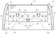
図4において外刃11は、シート状の網刃からなる刃本体21と、刃本体21の装着ベース22に固定される補強板23とからなる。装着ベース22は、刃本体21の一対の長辺部に沿って設けてあり、一対の装着ベース22の間に網刃からなる切刃を形成してある。補強板23は、左右横長のプラスチック成形品であり、板面の左右2箇所に四角形の掛止穴24が開口しており、板面の長手方向に沿って7個の溶着ピン25を直線列状に設けてある。外刃11において、装着ベース22と補強板23とを含む部分を取付基部26とする。   In FIG. 4, the outer blade 11 includes a blade body 21 composed of a sheet-like mesh blade, and a reinforcing plate 23 fixed to the mounting base 22 of the blade body 21. The mounting base 22 is provided along a pair of long sides of the blade body 21, and a cutting blade formed of a mesh blade is formed between the pair of mounting bases 22. The reinforcing plate 23 is a horizontally molded plastic product with left and right sides. Square retaining holes 24 are opened at two left and right sides of the plate surface, and seven welding pins 25 are arranged in a straight line along the longitudinal direction of the plate surface. It is provided in the shape. In the outer blade 11, a portion including the mounting base 22 and the reinforcing plate 23 is referred to as an attachment base portion 26.

補強板23は、後述するように外刃ホルダー12の前後壁31・32の内面に掛止装着される。両補強板23のうち、外刃ホルダー12の後側内面壁32aに掛止される補強板23は、装着ベース22と重合する部分のみで形成するが、図1および図4に示すように、外刃ホルダー12の前側内面壁31aに掛止される補強板23は、装着ベース22と重合する連結領域Z1と、連結領域Z1に連続して装着ベース22からはみ出る操作領域Z2とを一体に備えている。先の掛止穴24は連結領域Z1に開口している。   As will be described later, the reinforcing plate 23 is hooked on the inner surfaces of the front and rear walls 31 and 32 of the outer blade holder 12. Of both the reinforcing plates 23, the reinforcing plate 23 hooked to the rear inner wall 32a of the outer blade holder 12 is formed only by a portion overlapping with the mounting base 22, but as shown in FIG. 1 and FIG. The reinforcing plate 23 hooked to the front inner wall 31a of the outer blade holder 12 is integrally provided with a connection region Z1 overlapping with the mounting base 22 and an operation region Z2 protruding from the mounting base 22 continuously to the connection region Z1. ing. The previous retaining hole 24 opens to the connection region Z1.

溶着ピン25が設けられる板面の裏面側で、操作領域Z2の左右中央部分には、取付基部26を後述する掛止フック35から分離操作するための操作部27を形成してある。図5に示すように操作部27は、操作方向を示す指標を兼ねる逆三角形状の主突起27aと、主突起27aの上側に隣接配置される一文字状の突起27bとからなり、主突起27aの頂角部分が操作領域Z2の下縁に近接する状態で形成してある。   On the back surface side of the plate surface on which the welding pins 25 are provided, an operation portion 27 for separating and attaching the attachment base portion 26 from a latch hook 35 described later is formed in the left and right center portion of the operation region Z2. As shown in FIG. 5, the operation unit 27 includes an inverted triangular main protrusion 27a that also serves as an index indicating the operation direction, and a single-character-shaped protrusion 27b that is disposed adjacent to the upper side of the main protrusion 27a. The apex angle portion is formed in the state close to the lower edge of the operation area Z2.

外刃ホルダー12は、逆U字状に形成される左右一対の側壁30と、両側壁30を繋ぐ前壁31および後壁32とを一体に備えたプラスチック成形品であり、上下面がそれぞれ開口している。下側の開口は、かみそりヘッド7の上面に膨出した装着部7aに外嵌する装着開口33として機能し、上側の開口は外刃11の湾曲する切刃部分を露出させるために設けてある。   The outer blade holder 12 is a plastic molded product integrally including a pair of left and right side walls 30 formed in an inverted U shape, and a front wall 31 and a rear wall 32 that connect both side walls 30, and the upper and lower surfaces thereof are open. is doing. The lower opening functions as a mounting opening 33 that is externally fitted to the mounting portion 7 a that bulges on the upper surface of the razor head 7, and the upper opening is provided to expose the curved cutting edge portion of the outer blade 11. .

外刃ホルダー12の前壁31および後壁32の内面左右には、それぞれ外刃11の掛止穴24を掛止するための掛止フック35を一体に形成してある。掛止フック35は、図1に示すように前側内面壁31aまたは後側内面壁32aから水平に突出する掛止腕36と、掛止腕36の突端から下向きに折れ曲がる抜止爪37とで逆L字状に形成してあり、両者36・37の上隅部分に斜めのガイド面38が設けてある。   On the left and right inner surfaces of the front wall 31 and the rear wall 32 of the outer blade holder 12, latch hooks 35 for latching the retaining holes 24 of the outer blade 11 are formed integrally. As shown in FIG. 1, the latch hook 35 is reversely formed by a latch arm 36 that projects horizontally from the front inner wall 31 a or the rear inner wall 32 a and a retaining claw 37 that bends downward from the protruding end of the latch arm 36. It is formed in a letter shape, and an oblique guide surface 38 is provided at the upper corner of both 36 and 37.

図3に示すように、掛止フック35に掛止装着された状態の外刃11の取り外し操作を確実に行うために、外刃ホルダー12の前側内面壁31aに左右一対の支点突起40を分離配置する。さらに、操作部27に臨む前側内面壁31aに逃げ凹部42を形成する。支点突起40は突端の接当面41が丸められた三角形状のリブ状突起からなり、図5に示すように掛止フック35の近傍で、掛止フック35の掛止腕36の中央と操作部27の中央とを結ぶ仮想線L上に接当面41が位置するように支点突起40を設ける。これにより、各掛止フック35と操作部27との距離、および各支点突起40と操作部27との距離がそれぞれ等しく設定される。   As shown in FIG. 3, a pair of left and right fulcrum protrusions 40 are separated from the front inner wall 31a of the outer blade holder 12 in order to reliably remove the outer blade 11 that is hooked and attached to the hook 35. Deploy. Further, a relief recess 42 is formed in the front inner wall 31 a facing the operation unit 27. The fulcrum protrusion 40 is formed of a triangular rib-shaped protrusion with the contact surface 41 of the protrusion being rounded, and as shown in FIG. 5, in the vicinity of the hook hook 35, the center of the hook arm 36 and the operation portion. The fulcrum protrusion 40 is provided so that the contact surface 41 is positioned on an imaginary line L connecting the center of 27. Thereby, the distance between each latching hook 35 and the operation part 27 and the distance between each fulcrum protrusion 40 and the operation part 27 are set equal.

逃げ凹部42は、操作部27に臨む前側内面壁31aの上寄り中央部分から装着開口33にわたる領域に設けられて、その外郭線が上凸状の湾曲線となるように凹み形成してある。このように広い範囲に亘って逃げ凹部42を形成すると、外刃11を掛止フック35から取り外すとき、弾性変形された取付基部26を凹部内に受け入れて、取付基部26が前側内面壁31aに接当干渉するのを遅らせることができる。したがって、取付基部26を充分に内方傾動させることができる。先の支点突起40は、その下側の突出基端が逃げ凹部42の外郭線に連続するように形成してある。   The escape recess 42 is provided in a region extending from the upper center portion of the front inner wall 31a facing the operation portion 27 to the mounting opening 33, and is formed so that its outline is an upwardly curved line. When the relief recess 42 is formed over such a wide range, when the outer blade 11 is removed from the latch hook 35, the elastically deformed attachment base 26 is received in the recess, and the attachment base 26 is formed on the front inner wall 31a. It is possible to delay the contact interference. Therefore, the mounting base 26 can be tilted inward sufficiently. The fulcrum projection 40 is formed so that the lower protruding base end thereof is continuous with the outline of the escape recess 42.

図4に示すように、外刃ホルダー12の後壁32には、きわ剃り刃ユニット6を受け入れる切欠44が形成されている。両側壁30とヘッドケースとの間には、かみそりヘッド7に装着した外刃ホルダー12をロックするロック構造が設けてある。図2においてロック構造は、本体ケース1の上部両側から露出するロック解除ボタン45と、ロック解除ボタン45と一体に設けられるロック爪46と、ロック爪46を係合付勢するロックばね47と、ロック爪46に対応して両側壁30の内面に凹み形成されるロック凹部48とからなる。左右のロック解除ボタン45をロックばね47の付勢力に抗して押し込み操作すると、ロック爪46とロック凹部48との係合が解除されるので、外刃ホルダー12をかみそりヘッド7から取り外すことができる。   As shown in FIG. 4, a notch 44 for receiving the shaving blade unit 6 is formed in the rear wall 32 of the outer blade holder 12. A lock structure is provided between the side walls 30 and the head case to lock the outer blade holder 12 attached to the razor head 7. In FIG. 2, the lock structure includes a lock release button 45 exposed from both upper sides of the main body case 1, a lock claw 46 provided integrally with the lock release button 45, a lock spring 47 that engages and urges the lock claw 46, A lock recess 48 is formed in the inner surface of both side walls 30 corresponding to the lock claw 46. When the left and right lock release buttons 45 are pushed against the urging force of the lock spring 47, the engagement between the lock claw 46 and the lock recess 48 is released, so that the outer blade holder 12 can be removed from the razor head 7. it can.

外刃ホルダー12をかみそりヘッド7に装着した状態では、図3に示すように外刃11が内刃10と共にばね17で押し上げ操作されて、逆U字状に保形されている。このとき、掛止穴24の下周面が掛止フック35の掛止腕36の下面で受け止められて、外刃11の上方移動が規制されている。外刃ホルダー12をかみそりヘッド7から取り外すと、図6に示すように外刃11は外刃ホルダー12の前後壁31・32で受け止められて、逆U字状の湾曲姿勢に保持される。   In the state where the outer blade holder 12 is mounted on the razor head 7, the outer blade 11 is pushed up by the spring 17 together with the inner blade 10 as shown in FIG. At this time, the lower peripheral surface of the retaining hole 24 is received by the lower surface of the retaining arm 36 of the retaining hook 35, and the upward movement of the outer blade 11 is restricted. When the outer blade holder 12 is removed from the razor head 7, the outer blade 11 is received by the front and rear walls 31 and 32 of the outer blade holder 12 as shown in FIG.

外刃11を取り外す場合には、指先を操作部27にあてがって、図1に示すように取付基部26を支点突起40に押し付けて、取付基部26を実線で示すように内方傾動させる。このとき、支点突起40の接当面41で受け止められた取付基部26は、支点突起40の間の壁面が緩やかに湾曲し、掛止穴24の周辺壁が前側内面壁31aから浮き離れる向きに傾動する。つまり、仮想線L上に位置する操作部27と掛止穴24とは、支点突起40を支点にして互いに逆向きに動く。その結果、掛止穴24は掛止腕36から抜け出て、その上周面がガイド面38に臨む。この状態を保持したままで、指先で操作部27を押し下げ操作すると、掛止穴24が抜止爪37に沿って下降するので、前側の取付基部26を掛止フック35から分離できる。併行して後側の取付基部26に設けた掛止穴24が前方に傾動しながらガイド面38を乗り越えるので、後側の掛止穴24を抜止爪37に沿って下降させることにより、外刃11の全体を外刃ホルダー12から取り外すことができる。   When the outer blade 11 is removed, the fingertip is applied to the operation portion 27, the attachment base portion 26 is pressed against the fulcrum protrusion 40 as shown in FIG. 1, and the attachment base portion 26 is tilted inward as indicated by a solid line. At this time, the mounting base portion 26 received by the contact surface 41 of the fulcrum protrusion 40 is tilted in such a direction that the wall surface between the fulcrum protrusions 40 is gently curved and the peripheral wall of the retaining hole 24 is lifted away from the front inner wall 31a. To do. That is, the operation unit 27 and the retaining hole 24 positioned on the imaginary line L move in opposite directions with the fulcrum protrusion 40 as a fulcrum. As a result, the retaining hole 24 comes out of the retaining arm 36 and its upper peripheral surface faces the guide surface 38. If the operation part 27 is pushed down with the fingertip while this state is maintained, the retaining hole 24 descends along the retaining pawl 37, so that the front mounting base 26 can be separated from the retaining hook 35. At the same time, the latching hole 24 provided in the rear mounting base 26 climbs over the guide surface 38 while tilting forward, so that the outer cutter is lowered by lowering the rear latching hole 24 along the retaining pawl 37. 11 can be removed from the outer blade holder 12.

図7は補強板23に関する本発明の別実施例を示す。そこでは、支点突起40を補強板23と一体に形成した。支点突起40は丸ピン状に形成してあり、上記の実施例における支点突起と同じ位置に形成した。他は先の実施例と同じであるので、同じ部材に同じ符号を付してその説明を省略する。   FIG. 7 shows another embodiment of the present invention relating to the reinforcing plate 23. There, the fulcrum protrusion 40 is formed integrally with the reinforcing plate 23. The fulcrum protrusion 40 is formed in a round pin shape, and is formed at the same position as the fulcrum protrusion in the above-described embodiment. Since others are the same as the previous embodiment, the same reference numerals are assigned to the same members, and descriptions thereof are omitted.

上記の実施例以外に、操作部27は凹部として形成することができ、要は指先が引っ掛かる滑止構造であれば、その構造の違いは問わない。掛止フック35におけるガイド面38は部分円弧面で形成することができる。支点突起40は必ずしも左右に分離配置する必要はなく、例えば左右横長のリブ状に形成することができる。その場合のリブは、操作部27より上方で、しかも左右一対の掛止フック35より下方に設けることが好ましい。操作領域Z2は装着ベース22からはみ出ている必要はなく、その一部あるいは全部が装着ベース22と重合していてもよい。操作部27や支点突起40などの取外構造は、前後いずれか一方に設けてあればよいが、必要があれば前後双方に設けることができる。   In addition to the above embodiment, the operation portion 27 can be formed as a concave portion, and the difference in structure is not limited as long as it is a non-slip structure in which a fingertip is caught. The guide surface 38 in the latching hook 35 can be formed by a partial arc surface. The fulcrum protrusion 40 does not necessarily have to be separately arranged on the left and right, and can be formed in, for example, a horizontally long rib shape. In this case, the rib is preferably provided above the operation unit 27 and below the pair of left and right hooks 35. The operation area Z <b> 2 does not need to protrude from the mounting base 22, and a part or all of it may overlap with the mounting base 22. The detaching structure such as the operation portion 27 and the fulcrum protrusion 40 may be provided on either the front or rear side, but can be provided on both the front and rear sides if necessary.

外刃の取付構造を示す断面図である。It is sectional drawing which shows the attachment structure of an outer blade. 電気かみそりの正面図である。It is a front view of an electric razor. かみそりヘッドの縦断側面図である。It is a vertical side view of a razor head. 外刃と外刃ホルダーの分解斜視図である。It is a disassembled perspective view of an outer blade and an outer blade holder. 外刃ホルダーの縦断正面図である。It is a vertical front view of an outer blade holder. 外刃ホルダーの縦断側面図である。It is a vertical side view of an outer blade holder. 補強板の別実施例を示す断面図である。It is sectional drawing which shows another Example of a reinforcement board.

符号の説明Explanation of symbols

7 かみそりヘッド
11 外刃
12 外刃ホルダー
21 刃本体
22 装着ベース
23 補強板
24 掛止穴
26 取付基部
27 操作部
35 掛止フック
40 支点突起
7 Razor head 11 Outer blade 12 Outer blade holder 21 Blade main body 22 Mounting base 23 Reinforcement plate 24 Retaining hole 26 Mounting base 27 Operating portion 35 Retaining hook 40 Supporting protrusion

Claims (5)

かみそりヘッド(7)に着脱される外刃ホルダー(12)と、外刃ホルダー(12)で逆U字状に保持される外刃(11)とを備えており、
外刃(11)は、シート状の網刃からなる刃本体(21)と、刃本体(21)の装着ベース(22)に固定される補強板(23)とを備えており、
装着ベース(22)と補強板(23)とを含む取付基部(26)の左右に、外刃ホルダー(12)の内面に突設した逆L字状の掛止フック(35)に下方から掛止装着される掛止穴(24)が設けられており、
左右の掛止フック(35)の間に位置する外刃ホルダー(12)の内面壁と、前記内面壁と対向する取付基部(26)とのいずれか一方に支点突起(40)が設けられており、
取付基部(26)を支点突起(40)に押し付けて、取付基部(26)を内方傾動させながら分離操作するための操作部(27)が取付基部(26)に形成してあり、
装着ベース(22)の内面側に補強板(23)が固定されて、補強板(23)の下縁寄りに操作部(27)が形成されており、
外刃ホルダー(12)の掛止フック(35)の近傍に、左右一対の支点突起(40)が分離配置されており、
支点突起(40)の接当面(41)が、掛止フック(35)の掛止腕(36)の中央と操作部(27)の中央とを結ぶ仮想線(L)上に設けてある電気かみそり。
An outer blade holder (12) attached to and detached from the razor head (7), and an outer blade (11) held in an inverted U shape by the outer blade holder (12),
The outer blade (11) includes a blade body (21) composed of a sheet-like mesh blade, and a reinforcing plate (23) fixed to the mounting base (22) of the blade body (21).
From left and right on the mounting base (26) including the mounting base (22) and the reinforcing plate (23), it is hooked from below on the inverted L-shaped hooks (35) protruding from the inner surface of the outer blade holder (12). There is a retaining hole (24) to be fixed,
A fulcrum protrusion (40) is provided on one of the inner wall of the outer blade holder (12) located between the left and right hooks (35) and the mounting base (26) facing the inner wall. And
Against the mounting base (26) to the fulcrum projection (40), an operation unit for separating operation while the mounting base (26) is inwardly tilted (27) Ri Tare formed on the mounting base (26),
A reinforcing plate (23) is fixed to the inner surface side of the mounting base (22), and an operation portion (27) is formed near the lower edge of the reinforcing plate (23).
A pair of left and right fulcrum protrusions (40) are separately arranged in the vicinity of the latching hook (35) of the outer blade holder (12),
The contact surface (41) of the fulcrum protrusion (40) is provided on an imaginary line (L) connecting the center of the latching arm (36) of the latching hook (35) and the center of the operating portion (27). Razor.
かみそりヘッド(7)の背面側に、きわ剃り刃ユニット(6)が配置されており、
外刃ホルダー(12)の前側内面壁(31a)と、前側内面壁(31a)に対向する取付基部(26)とのいずれか一方に、支点突起(40)が設けてある請求項1記載の電気かみそり。
A shaving blade unit (6) is arranged on the back side of the razor head (7),
The fulcrum protrusion (40) is provided in any one of the front inner wall (31a) of an outer blade holder (12) and the attachment base (26) facing a front inner wall (31a). Electric razor.
装着ベース(22)の内面側に補強板(23)が固定されて、補強板(23)の下縁寄りに操作部(27)が形成されており、
外刃ホルダー(12)の掛止フック(35)の近傍に、左右一対の支点突起(40)が分離配置されており、
各掛止フック(35)と操作部(27)との距離、および各支点突起(40)と操作部(27)との距離が、それぞれ等しく設定してある請求項1または2記載の電気かみそり。
A reinforcing plate (23) is fixed to the inner surface side of the mounting base (22), and an operation portion (27) is formed near the lower edge of the reinforcing plate (23).
A pair of left and right fulcrum protrusions (40) are separately arranged in the vicinity of the latching hook (35) of the outer blade holder (12),
The electric shaver according to claim 1 or 2, wherein the distance between each latching hook (35) and the operating portion (27) and the distance between each fulcrum protrusion (40) and the operating portion (27) are set to be equal. .
補強板(23)が、刃本体(21)の装着ベース(22)に重合される連結領域(Z1)と、連結領域(Z1)から下方に連出される操作領域(Z2)とを備えていて、操作領域(Z2)の左右中央に操作部(27)が設けられており、
操作部(27)に臨む外刃ホルダー(12)の内面壁に、弾性変形された取付基部(26)を受け入れる逃げ凹部(42)が形成されている請求項1、2または3記載の電気かみそり。
The reinforcing plate (23) includes a connection region (Z1) that is superposed on the mounting base (22) of the blade body (21), and an operation region (Z2) that extends downward from the connection region (Z1). The operation section (27) is provided at the center of the left and right of the operation area (Z2)
The electric shaver according to claim 1, 2 or 3, wherein a relief recess (42) for receiving the elastically deformed mounting base (26) is formed on the inner wall of the outer blade holder (12) facing the operation portion (27). .
支点突起(40)の突出基端が、逃げ凹部(42)の外郭線に隣接して形成してある請求項4記載の電気かみそり。 The electric shaver according to claim 4, wherein the protruding proximal end of the fulcrum protrusion (40) is formed adjacent to the outline of the relief recess (42) .
JP2005315401A 2005-10-28 2005-10-28 Electric razor Expired - Fee Related JP4775889B2 (en)

Priority Applications (1)

Application Number Priority Date Filing Date Title
JP2005315401A JP4775889B2 (en) 2005-10-28 2005-10-28 Electric razor

Applications Claiming Priority (1)

Application Number Priority Date Filing Date Title
JP2005315401A JP4775889B2 (en) 2005-10-28 2005-10-28 Electric razor

Publications (2)

Publication Number Publication Date
JP2007117503A JP2007117503A (en) 2007-05-17
JP4775889B2 true JP4775889B2 (en) 2011-09-21

Family

ID=38141983

Family Applications (1)

Application Number Title Priority Date Filing Date
JP2005315401A Expired - Fee Related JP4775889B2 (en) 2005-10-28 2005-10-28 Electric razor

Country Status (1)

Country Link
JP (1) JP4775889B2 (en)

Family Cites Families (3)

* Cited by examiner, † Cited by third party
Publication number Priority date Publication date Assignee Title
JPS5011781A (en) * 1973-06-04 1975-02-06
DE19521299C1 (en) * 1995-06-12 1996-03-21 Braun Ag Electric razor with pivoted cutter for long hair
JP4507136B2 (en) * 1999-11-22 2010-07-21 九州日立マクセル株式会社 Electric razor

Also Published As

Publication number Publication date
JP2007117503A (en) 2007-05-17

Similar Documents

Publication Publication Date Title
US11034038B2 (en) Razor handle assembly and razor comprising the same
US20100251555A1 (en) Shaver
JP3632240B2 (en) Reciprocating electric razor
JP2005040358A (en) Shaver
JP4711330B2 (en) Electric razor
KR100635590B1 (en) Electric shaver
KR101668230B1 (en) Razor
JP4789188B2 (en) Electric razor
JP4775889B2 (en) Electric razor
JP5838335B2 (en) Electric razor
JP4761294B2 (en) Electric razor
JP2020129594A (en) Unit mounting structure and electronic equipment
JP4953233B2 (en) Electric razor
JP4507167B2 (en) Electric razor
JP4569983B2 (en) Electric razor
JP2659242B2 (en) Electric razor
JP4863271B2 (en) Electric razor
JP3875148B2 (en) punch
JP5288406B2 (en) Electric razor
JP6180944B2 (en) Electric razor
JP4171645B2 (en) Replaceable blade cutter knife
JP2005052556A (en) Electric razor
JP5388100B2 (en) Electric razor
JP4122855B2 (en) Electric razor
JP6656105B2 (en) Electric razor

Legal Events

Date Code Title Description
RD02 Notification of acceptance of power of attorney

Free format text: JAPANESE INTERMEDIATE CODE: A7422

Effective date: 20070716

A621 Written request for application examination

Free format text: JAPANESE INTERMEDIATE CODE: A621

Effective date: 20080318

A977 Report on retrieval

Free format text: JAPANESE INTERMEDIATE CODE: A971007

Effective date: 20100924

A131 Notification of reasons for refusal

Free format text: JAPANESE INTERMEDIATE CODE: A131

Effective date: 20110406

A521 Written amendment

Free format text: JAPANESE INTERMEDIATE CODE: A523

Effective date: 20110526

TRDD Decision of grant or rejection written
A01 Written decision to grant a patent or to grant a registration (utility model)

Free format text: JAPANESE INTERMEDIATE CODE: A01

Effective date: 20110622

A01 Written decision to grant a patent or to grant a registration (utility model)

Free format text: JAPANESE INTERMEDIATE CODE: A01

A61 First payment of annual fees (during grant procedure)

Free format text: JAPANESE INTERMEDIATE CODE: A61

Effective date: 20110623

R150 Certificate of patent or registration of utility model

Free format text: JAPANESE INTERMEDIATE CODE: R150

FPAY Renewal fee payment (event date is renewal date of database)

Free format text: PAYMENT UNTIL: 20140708

Year of fee payment: 3

FPAY Renewal fee payment (event date is renewal date of database)

Free format text: PAYMENT UNTIL: 20140708

Year of fee payment: 3

S111 Request for change of ownership or part of ownership

Free format text: JAPANESE INTERMEDIATE CODE: R313111

FPAY Renewal fee payment (event date is renewal date of database)

Free format text: PAYMENT UNTIL: 20140708

Year of fee payment: 3

R350 Written notification of registration of transfer

Free format text: JAPANESE INTERMEDIATE CODE: R350

FPAY Renewal fee payment (event date is renewal date of database)

Free format text: PAYMENT UNTIL: 20140708

Year of fee payment: 3

R250 Receipt of annual fees

Free format text: JAPANESE INTERMEDIATE CODE: R250

R250 Receipt of annual fees

Free format text: JAPANESE INTERMEDIATE CODE: R250

R250 Receipt of annual fees

Free format text: JAPANESE INTERMEDIATE CODE: R250

LAPS Cancellation because of no payment of annual fees