JP4775111B2 - Crew protection device - Google Patents
Crew protection device Download PDFInfo
- Publication number
- JP4775111B2 JP4775111B2 JP2006142932A JP2006142932A JP4775111B2 JP 4775111 B2 JP4775111 B2 JP 4775111B2 JP 2006142932 A JP2006142932 A JP 2006142932A JP 2006142932 A JP2006142932 A JP 2006142932A JP 4775111 B2 JP4775111 B2 JP 4775111B2
- Authority
- JP
- Japan
- Prior art keywords
- seat
- airbag
- partition
- chamber
- inflator
- Prior art date
- Legal status (The legal status is an assumption and is not a legal conclusion. Google has not performed a legal analysis and makes no representation as to the accuracy of the status listed.)
- Expired - Fee Related
Links
Images


Classifications
-
- B—PERFORMING OPERATIONS; TRANSPORTING
- B60—VEHICLES IN GENERAL
- B60N—SEATS SPECIALLY ADAPTED FOR VEHICLES; VEHICLE PASSENGER ACCOMMODATION NOT OTHERWISE PROVIDED FOR
- B60N2/00—Seats specially adapted for vehicles; Arrangement or mounting of seats in vehicles
- B60N2/24—Seats specially adapted for vehicles; Arrangement or mounting of seats in vehicles for particular purposes or particular vehicles
- B60N2/42—Seats specially adapted for vehicles; Arrangement or mounting of seats in vehicles for particular purposes or particular vehicles the seat constructed to protect the occupant from the effect of abnormal g-forces, e.g. crash or safety seats
- B60N2/427—Seats or parts thereof displaced during a crash
- B60N2/42709—Seats or parts thereof displaced during a crash involving residual deformation or fracture of the structure
- B60N2/42718—Seats or parts thereof displaced during a crash involving residual deformation or fracture of the structure with anti-submarining systems
-
- B—PERFORMING OPERATIONS; TRANSPORTING
- B60—VEHICLES IN GENERAL
- B60R—VEHICLES, VEHICLE FITTINGS, OR VEHICLE PARTS, NOT OTHERWISE PROVIDED FOR
- B60R21/00—Arrangements or fittings on vehicles for protecting or preventing injuries to occupants or pedestrians in case of accidents or other traffic risks
- B60R21/02—Occupant safety arrangements or fittings, e.g. crash pads
- B60R21/16—Inflatable occupant restraints or confinements designed to inflate upon impact or impending impact, e.g. air bags
- B60R21/20—Arrangements for storing inflatable members in their non-use or deflated condition; Arrangement or mounting of air bag modules or components
- B60R21/207—Arrangements for storing inflatable members in their non-use or deflated condition; Arrangement or mounting of air bag modules or components in vehicle seats
Landscapes
- Engineering & Computer Science (AREA)
- Mechanical Engineering (AREA)
- Aviation & Aerospace Engineering (AREA)
- Transportation (AREA)
- Air Bags (AREA)
- Seats For Vehicles (AREA)
Description
車両が衝突した場合にシートクッションの前端部分を持ち上げる装置がこれまでにも提供されてきた。これは、正面衝突の場合に、乗員がシートベルトを装着していても腰ベルトから下向きに押し出されるサブマリン現象を避けるためのものである。例えば、日本の未審査の特許出願特開平10−309967号においては、シートクッションの前端が筒型アクチュエータによって持ち上げられるように構成された車両シートが開示されている。また、日本の未審査特許出願特開平10−217818号においては、シートクッションの前端がエアバッグによって持ち上げられる車両シートが開示されている。これら2つの公開特許出願は、この参照によって本開示に含まれる。 In the past, devices for lifting the front end portion of the seat cushion in the event of a vehicle collision have been provided. This is to avoid a submarine phenomenon that is pushed downward from the waist belt even if the occupant is wearing the seat belt in the case of a frontal collision. For example, Japanese unexamined Japanese Patent Application No. Hei 10-309967 discloses a vehicle seat configured such that the front end of a seat cushion is lifted by a cylindrical actuator. Japanese unexamined patent application No. 10-217818 discloses a vehicle seat in which the front end of a seat cushion is lifted by an airbag. These two published patent applications are included in this disclosure by this reference.
本出願においては、シートクッションの中に収納し得るエアバッグを含む車両乗員保護用の乗員保護装置が開示される。この装置は、車両の前部シートまたは後部シートのいずれに対しても構成することができる。 In the present application, an occupant protection device for vehicle occupant protection including an airbag that can be housed in a seat cushion is disclosed. This device can be configured for either the front seat or the rear seat of the vehicle.
乗員保護装置の実施形態によれば、この装置は、エアバッグの特性を調節し得るように制御することができる。例えば、エアバッグの膨張を次のような代表的な機構によって制御することができる。すなわち、インフレータの構成及び設計、チャンバの大きさと位置と個数とを含むエアバッグの構成、エアバッグガス抜き孔の個数及び位置、エアバッグチャンバ間の流体接続配置、エアバッグ及びエアバッグチャンバとインフレータとの間の流体接続配置、圧力制御機構または膨張ガス制御装置の装備、等である。 According to an embodiment of the occupant protection device, the device can be controlled to adjust the characteristics of the airbag. For example, the inflation of the airbag can be controlled by the following typical mechanism. That is, the configuration and design of the inflator, the configuration of the airbag including the size, position, and number of chambers, the number and position of the airbag vent holes, the fluid connection arrangement between the airbag chambers, the airbag, the airbag chamber, and the inflator Fluid connection arrangement between, pressure control mechanism or inflation gas control equipment, etc.
さらに、例として、内部圧力及び/または展開時間を調節することができる。これを実現するには、エアバッグ膨張用のガスを供給するインフレータを、インフレータが種々のレベルのガス出力を有するように制御するとよい。 Further, by way of example, internal pressure and / or deployment time can be adjusted. To achieve this, the inflator that supplies the air bag inflation gas may be controlled so that the inflator has various levels of gas output.
別の代表的な実施形態においては、インフレータの出力を、車両センサによって得られる情報に従って制御することができる。例えば、この装置に、センサから情報を受信して衝突の重大性とパターンとを決定する制御器を備え付けることができる。センサは、例えば、加速度、構造の無損傷性、圧力、速度等のような種々の車両特性を感知するように構成することができる。またこの代わりに、乗員の特性、例えば体格、体重、姿勢、シートベルトの使用または状態、あるいはその他類似情報のような特性を感知するセンサを用いることもできる。 In another exemplary embodiment, the output of the inflator can be controlled according to information obtained by the vehicle sensor. For example, the device can be equipped with a controller that receives information from the sensor to determine the severity and pattern of the collision. The sensor can be configured to sense various vehicle characteristics such as, for example, acceleration, structural integrity, pressure, speed, and the like. Alternatively, sensors that sense occupant characteristics such as physique, weight, posture, seat belt usage or condition, or other similar information may be used.
上記にように、この装置は、センサから受信した情報に基づいてエアバッグの展開を制御する制御器を含むことができる。例えば、インフレータを制御してインフレータの作動時間(Time to Fire:TTF)を制御し、かつ、インフレータの出力を制御してエアバッグの内部圧力を調節することができる。エアバッグの内部圧力は、全エアバッグについても、あるいはエアバッグの個々のチャンバについても調節することができる。 As described above, the device can include a controller that controls the deployment of the airbag based on information received from the sensor. For example, the inflator can be controlled to control the inflator operating time (Time to Fire: TTF), and the output of the inflator can be controlled to adjust the internal pressure of the airbag. The internal pressure of the airbag can be adjusted for the entire airbag or for individual chambers of the airbag.
代表的な実施形態によれば、エアバッグを、インフレータのガス出力によって膨張する1つ以上のチャンバに分割することができる。インフレータからの供給ガスは1つ以上のチャンバに流入してエアバッグを膨張させる。 According to an exemplary embodiment, the airbag can be divided into one or more chambers that are inflated by the gas output of the inflator. Supply gas from the inflator flows into one or more chambers to inflate the airbag.
別の実施形態においては、インフレータを、エアバッグの複数のチャンバの1つに装着することができる。インフレータが装着されたチャンバと、インフレータが装着されない他のチャンバとの間に1つ以上の連絡孔を設けて、インフレータからの供給ガスがチャンバ間を流れるようにすることができる。例えば、1つの複式インフレータを組み込んで、複式インフレータがエアバッグの1つ以上のチャンバを貫通するようにすることもできる。 In another embodiment, the inflator can be attached to one of the plurality of chambers of the airbag. One or more communication holes may be provided between the chamber in which the inflator is mounted and another chamber in which the inflator is not mounted so that the supply gas from the inflator flows between the chambers. For example, a single inflator may be incorporated so that the double inflator penetrates one or more chambers of the airbag.
参考例においては、インフレータが、2つ以上の分枝または流路に分割された膨張流路を有することができる。 In a reference example , the inflator can have an expansion channel that is divided into two or more branches or channels.
本発明の1つの実施形態においては、エアバッグに、エネルギー吸収(Energy Absorption:EA)レベルを制御する1つ以上のガス抜き孔を設けることができる。 In one embodiment of the present invention, the airbag may be provided with one or more vent holes that control the energy absorption (EA) level.
乗員(車両運転者を含むどの車両乗員をも含む)保護装置は、乗員の負傷を一層効果的に低減かつ/または回避するために、衝突及び/または乗員の状況に応じてエアバッグの展開を制御するように配置することができる。 The occupant (including any vehicle occupant, including vehicle driver) protection device deploys the airbag in response to a crash and / or occupant situation to more effectively reduce and / or avoid occupant injury. Can be arranged to control.
米国特許第6,715,788号は車両シートに収納されるエアバッグとエアバッグ装置との種々の配置を示している。米国特許第6,715,788号はこの参照によってその全体がそのまま本開示に含まれる。ここに開示するエアバッグ及び乗員保護装置は、米国特許第6,715,788号に示される装置と配置との中に組み込むことができる。 U.S. Pat. No. 6,715,788 shows various arrangements of airbags and airbag devices housed in a vehicle seat. US Pat. No. 6,715,788 is hereby incorporated by reference in its entirety. The airbag and occupant protection device disclosed herein can be incorporated into the device and arrangement shown in US Pat. No. 6,715,788.
前記の一般的な記述及び以下の詳細な説明は共に代表的事例を示しかつ説明するためだけのものであって、特許請求の範囲に記載される本発明を制限するものではないことが理解されるべきである。 It will be understood that both the foregoing general description and the following detailed description are exemplary and exemplary only and are not restrictive of the invention as claimed. Should be.
本明細書において開示する装置の実施形態を、図面を参照して説明する。以下に説明する各実施形態において、全図面を通して、同じ部品または類似部品を参照するには同じ番号を用いる。 Embodiments of an apparatus disclosed in this specification will be described with reference to the drawings. In each embodiment described below, the same reference numerals are used to refer to the same or similar parts throughout the drawings.
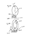
図1に示すように、乗員安全装置は車両シート10を含むことができる。このシートは、例えばシートバックレスト21とヘッドレスト22とを含むシートバック20を含むことができる。シート10は、また、シート底部30を含むことができ、このシート底部は、シートクッション31を支持するシート受け台33を含むことができる。
As shown in FIG. 1, the occupant safety device can include a
シートには種々の付属部品を配置することができる。例えば、シートはエアバッグ200とインフレータ300とを含むことができる。エアバッグはシートクッション31のシート表面34の下で膨張するように構成され、シートの乗員が前方へ動くのを阻止するために、シートクッションが上方へ動かされる。図1には、シートクッションが適応した位置32が示されている。エアバッグ200は、展開前の折り畳まれた状態が実線で示され、衝突後の展開した状態のエアバッグ201が点線で示されている。
Various accessory parts can be arranged on the seat. For example, the seat can include an
また、装置は、インフレータ300とエアバッグ200の展開とを制御するように構成された制御器400を含むことができる。例えば、装置は、センサ500から情報を受信して衝突の重大性とパターンとを決定する制御器400を含むことができる。センサ500は、例えば、加速度、構造の無損傷性、圧力、速度等のような種々の車両特性を感知するように構成することができる。またこの代わりに、乗員の特性、例えば体格、体重、姿勢、シートベルトの使用または状態、あるいはその他類似情報のような特性を感知するセンサ600を用いることもできる。
The apparatus can also include a
図2に示すように、インフレータ300がエアバッグ200の内部にあるかあるいはエアバッグ200の内側に入れ込まれる形で、インフレータ300をエアバッグ200の中に装着することができる。インフレータ300は、図2の例に示すように、インフレータの各端部から膨張ガスを供給する複式インフレータとすることができる。インフレータの“複式”特性は、複数の放出ポートを有する単一のインフレータか、あるいは、例えば別個の作動器によって別個に作動するインフレータを1対にした一体化されたインフレータ対によって作り出すことができる。
As shown in FIG. 2, the
図2aに示すように、エアバッグ200を第1チャンバ205及び第2チャンバ206に分割することができる。また、以下にさらに述べるように、エアバッグ200にはさらにチャンバを設けることができる。エアバッグ200が2個以上のチャンバを含む場合は、例えば図2bに示すように、1つ以上の連絡孔または開口210をチャンバ間に設けるとよい。連絡孔210は、インフレータ300からインフレータが装着されていないチャンバに膨張ガスを流す流路とするために用いることができる。図2の異なる図面に示されるように、異なる形態のチャンバ、チャンバ分割及び連絡孔を用いることができる。
As shown in FIG. 2 a, the
図3aに示すように、インフレータをエアバッグチャンバ205、206の間に配置することもできる。複式インフレータ300を、2つの膨張チャンバにまたがるようにエアバッグの内部に装着することができる。このような形態の場合は、インフレータは、膨張ガスを、インフレータの各端部から各チャンバ205、206に供給することができる。図3bに示すように、エアバッグのチャンバ間には連絡孔210を設けることができる。連絡孔210は、エアバッグのチャンバへの膨張ガスの流れを促進するのに用いることができる。これは、特に、インフレータの一方の側からの出力が、設計によってかあるいは実際上、もう一方の側からの出力に必ずしも等しくない場合に有効である。しかし、エアバッグ200は、エアバッグのチャンバ間の開口または孔210を含まないように構成することもできる。
An inflator can also be placed between the
図3bに示すように、インフレータ300は、インフレータからの膨張ガスを導くオリフィス301を含むことができる。インフレータのオリフィスまたは開口301は、膨張ガスを配分調整して供給するためにインフレータのチャンバ間に配分して設けることができる。1つの可能な配分方式は、各チャンバに同数のオリフィス301を設けることによって実現し得る。もちろんエアバッグの各チャンバの容積は異なっても差し支えないが、これは、オリフィス301の所要の配分を変えることになるであろう。
As shown in FIG. 3b, the inflator 300 can include an
図3bに示すように、エアバッグ200はガス抜き孔215をも含むことができる。このガス抜き孔は、エアバッグ200に接触する乗員からのエネルギー吸収(EA)レベルを制御するために設けることができる。ガス抜き孔215はエアバッグの縦方向または横方向のどちらに設けてもよい。
As shown in FIG. 3 b, the
図4に示すように、乗員保護装置は、エアバッグチャンバがパイプ220によって流体接続される構成を含むことができる。細長い複式タイプのインフレータ300が2つのチャンバ205、207にまたがっている。第3のチャンバ206が、2つのチャンバの1つ207に外部のパイプ220によって接続される。さらに、いずれか1つのチャンバにガス抜き孔215を設けるとよい。図5は、エアバッグ200が2つのチャンバ205、206を含む参考例を示す。図4及び5に示すように、エアバッグチャンバの大きさは変えることができる。
As shown in FIG. 4, the occupant protection device can include a configuration in which the airbag chamber is fluidly connected by a
図6aは、インフレータ300をエアバッグ200の外側に配置した参考例を示す。インフレータ300は、例えばパイプまたは導管302によってエアバッグに接続してエアバッグ200の外部に取り付けることができる。パイプ、チューブ、縫合流路、及びその他当分野で知られるガス供給構造を、膨張ガス導管302用として用いることができる。図6c及び6dに示すように、外部インフレータ300には種々のエアバッグチャンバ配置を組み合わせることができる。
FIG. 6 a shows a reference example in which the
図6aにおいては、複式インフレータ300が、エアバッグ200の外部に配置されて、膨張ガス導管302によってエアバッグ200の末端部に接続されている。膨張ガス導管は、図6c及び6dに示すように、1つ以上のチャンバを有するエアバッグに膨張ガスを供給するように配置することができる。この場合、膨張ガス導管を、エアバッグの同じチャンバまたは異なるチャンバに膨張ガスを供給するように配置することができる。例えば、膨張ガス導管を、一方の膨張ガス導管は第1チャンバに膨張ガスを供給し、もう一方の膨張ガス導管は第2チャンバに膨張ガスを供給するように配置することができる。
In FIG. 6 a, the
図7に示すように、インフレータの端部における膨張ガス導管302の1つを分枝303に分割して、その分割された膨張ガス導管が第2チャンバ206と第3チャンバ207とに膨張ガスを供給し、一方、インフレータのもう一方の端部の別個の膨張ガス導管は第1チャンバ205に膨張ガスを供給するようにすることもできる。膨張ガス導管を分枝させることは、エアバッグの別個のチャンバに膨張ガスを供給するために、あるいは、同じチャンバに膨張ガスを供給するために、あるいはエアバッグの同じチャンバと別個のチャンバとに膨張ガスを供給するために行うことができる。図7bに示すように、内部インフレータ300を、分枝305に分割される内部導管304に流体接続することもできる。
As shown in FIG. 7, one of the
図7aに示す参考例においては、エネルギー吸収(EA)レベルを制御するためにガス抜き孔215を設けることができる。ガス抜き孔はエアバッグの縦方向または横方向のどちらに設けてもよい。ガス抜き孔215は、ここに開示したエアバッグのどの実施形態においても設けることができる。
In the reference example shown in FIG. 7a, a
図8a及び8bは、乗員安全装置のさらに別の参考例を示す。例えば図8aに示すように、インフレータを、インフレータからの膨張ガスを受け入れるように構成されたガスチャンバ306の中に配置することができる。チャンバ306からのガスは単一または複数の導管を通してエアバッグ200に搬送することができる。図8bに示すように、エアバッグを内部チャンバ208と外部チャンバ209とに分離することができる。外部インフレータ300が、単一導管または図8bに示すような別個の導管分枝303から、チャンバ208、209に膨張ガスを供給することができる。また、エアバッグはガス抜き孔215を含むことができる。
Figures 8a and 8b show yet another reference example of an occupant safety device. For example, as shown in FIG. 8a, the inflator can be placed in a
図9aに示すように、インフレータ300をエアバッグ200の外部に配置して、導管302によってエアバッグと接続することができる。この場合、エアバッグは流体連結された4つのチャンバを含むことができるが、その1つのチャンバだけが導管に接続されている。その代わりに、図9cに示すように、インフレータを、導管302の分枝303によって2つ以上のチャンバに流体接続することもできる。
As shown in FIG. 9 a, the inflator 300 can be placed outside the
前記のいずれの実施形態においても、エアバッグは、エアバッグの内部圧力を効果的に制御する圧力制御器を含むことができる。例えば、図9dの参考例のように、圧力制御弁または逆止弁310を設けることができる。この弁は、インフレータ300から出る膨張ガス導管302、その膨張ガス導管の分枝の1つ、あるいは、2つ以上のエアバッグチャンバを接続する膨張ガス導管に装着することができる。
In any of the embodiments described above, the airbag can include a pressure controller that effectively controls the internal pressure of the airbag. For example, a pressure control valve or
当分野に精通した当業者が本発明の開示を見れば、本発明の範囲及び本質内で他の実施形態及び変形態様があり得ることを了解するであろう。従って、本発明の範囲及び本質内にある本開示から当分野に精通した当業者が想定し得るすべての変形態様は、本発明のさらに別の実施形態として包含されるべきである。本発明の範囲は、以下の特許請求の範囲に陳述される形で規定されるものとする。 Those skilled in the art will recognize from the disclosure of the present invention that there may be other embodiments and variations within the scope and essence of the invention. Accordingly, all variations that can be envisaged by a person skilled in the art from this disclosure that are within the scope and spirit of the present invention should be included as further embodiments of the present invention. The scope of the present invention shall be defined in the form set forth in the following claims.
Claims (5)
前記シートクッションの下側且つ該シート受け台の上側に置かれ、該シート受け台に支持されたエアバッグと、
前記エアバッグを膨張させる膨張ガスを生成するインフレータと、
を備えた乗員保護装置であって、
前記インフレータが前記エアバッグの内側に配置されており、
該エアバッグの内部は、隔壁により、シートの前方側の第1のチャンバと、シートの後方側の第2のチャンバとに分割されており、
該隔壁は上下方向に延在しており、該隔壁の上端部及び下端部は、それぞれ該エアバッグの上部側及び下部側の内周面に結合されており、
該第1のチャンバ内の左右方向の中央部に前記インフレータが配置されており、
該隔壁に、第1のチャンバと第2のチャンバとを連通する2個の連絡孔が設けられており、
該連絡孔同士は、シートの左右方向に間隔をあけて配置されており、左側の連絡孔は、該インフレータの左端よりもエアバッグの左端に近い位置に配置されており、右側の連絡孔は、該インフレータの右端よりもエアバッグの右端に近い位置に配置されており、
前記シート受け台の上面は、該エアバッグの底部よりもシート前方側において、該シート前方に向って上り勾配となるように延在していることを特徴とする乗員保護装置。 A seat cushion, a seat back , and a seat including a seat cradle for supporting the seat cushion ;
An airbag placed on the lower side of the seat cushion and on the upper side of the seat cradle and supported by the seat cradle ;
An inflator that generates inflation gas for inflating the airbag;
An occupant protection device comprising:
The inflator is disposed inside the airbag ;
The interior of the airbag is divided by a partition into a first chamber on the front side of the seat and a second chamber on the rear side of the seat,
The partition wall extends in the up-down direction, and the upper end portion and the lower end portion of the partition wall are respectively coupled to the inner peripheral surface on the upper side and the lower side of the airbag,
The inflator is disposed at a central portion in the left-right direction in the first chamber;
The partition wall is provided with two communication holes for communicating the first chamber and the second chamber,
The communication holes are spaced apart from each other in the left-right direction of the seat, the left communication hole is positioned closer to the left end of the airbag than the left end of the inflator, and the right communication hole is , Disposed at a position closer to the right end of the airbag than the right end of the inflator,
The occupant protection device according to claim 1, wherein the upper surface of the seat cradle extends so as to rise upward toward the front of the seat on the front side of the seat relative to the bottom of the airbag .
前記シートクッションの下側且つ該シート受け台の上側に置かれ、該シート受け台に支持されたエアバッグと、An airbag placed on the lower side of the seat cushion and on the upper side of the seat cradle and supported by the seat cradle;
前記エアバッグを膨張させる膨張ガスを生成するインフレータと、An inflator that generates inflation gas for inflating the airbag;
を備えた乗員保護装置であって、An occupant protection device comprising:
前記インフレータが前記エアバッグの内側に配置されており、The inflator is disposed inside the airbag;
該エアバッグの内部は、隔壁により、下半側の第1のチャンバと、上半側の第2のチャンバとに分割されており、The interior of the airbag is divided by a partition into a first chamber on the lower half side and a second chamber on the upper half side,
該隔壁は水平方向に延在しており、該隔壁のシート前方側及びシート後方側の両端部は、それぞれ該エアバッグのシート前方側及びシート後方側の内周面に結合されており、The partition wall extends in the horizontal direction, and both ends of the partition front side and the seat rear side of the partition wall are coupled to the inner peripheral surface of the airbag on the seat front side and the seat rear side, respectively.
該第1のチャンバ内の左右方向の中央部に前記インフレータが配置されており、The inflator is disposed at a central portion in the left-right direction in the first chamber;
該隔壁に、第1のチャンバと第2のチャンバとを連通する2個の連絡孔が設けられており、The partition wall is provided with two communication holes for communicating the first chamber and the second chamber,
該連絡孔同士は、シートの左右方向に間隔をあけて配置されており、左側の連絡孔は、該インフレータの左端よりもエアバッグの左端に近い位置に配置されており、右側の連絡孔は、該インフレータの右端よりもエアバッグの右端に近い位置に配置されており、The communication holes are spaced apart from each other in the left-right direction of the seat, the left communication hole is positioned closer to the left end of the airbag than the left end of the inflator, and the right communication hole is , Disposed at a position closer to the right end of the airbag than the right end of the inflator,
前記シート受け台の上面は、該エアバッグの底部よりもシート前方側において、該シート前方に向って上り勾配となるように延在していることを特徴とする乗員保護装置。The occupant protection device according to claim 1, wherein the upper surface of the seat cradle extends so as to rise upward toward the front of the seat on the front side of the seat relative to the bottom of the airbag.
前記シートクッションの下側且つ該シート受け台の上側に置かれ、該シート受け台に支持されたエアバッグと、An airbag placed on the lower side of the seat cushion and on the upper side of the seat cradle and supported by the seat cradle;
前記エアバッグを膨張させる膨張ガスを生成するインフレータと、An inflator that generates inflation gas for inflating the airbag;
を備えた乗員保護装置であって、An occupant protection device comprising:
前記インフレータが前記エアバッグの内側に配置されており、The inflator is disposed inside the airbag;
該エアバッグの内部に、該エアバッグの内部を複数のチャンバに分割する隔壁が設けられており、A partition that divides the interior of the airbag into a plurality of chambers is provided inside the airbag,
該隔壁は、The partition wall
上下方向に延在しており、該エアバッグ内部空間をシート前方側とシート後方側とに分割する第1の隔壁と、A first partition wall that extends in a vertical direction and divides the airbag interior space into a seat front side and a seat rear side;
該第1の隔壁の上下方向の中間部に連なり、且つ該第1の隔壁からシート前方側及びシート後方側に延在しており、該第1の隔壁よりもシート前方側及びシート後方側のエアバッグ内部空間をそれぞれ下半側と上半側とに分割する第2の隔壁とIt is connected to the middle part of the up-and-down direction of the first partition, and extends from the first partition to the front side of the seat and the rear side of the seat. A second partition that divides the air bag interior space into a lower half side and an upper half side, respectively
からなり、Consists of
該第1の隔壁の上端部及び下端部は、それぞれ該エアバッグの上部側及び下部側の内周面に結合されており、The upper end portion and the lower end portion of the first partition are respectively coupled to the inner peripheral surface on the upper side and the lower side of the airbag,
該第2の隔壁のシート前方側及びシート後方側の両端部は、それぞれ該エアバッグのシート前方側及びシート後方側の内周面に結合されており、Both end portions of the second partition wall on the front side and the rear side of the seat are respectively coupled to inner peripheral surfaces of the front side and the rear side of the airbag,
該エアバッグの内部は、The inside of the airbag is
該第1の隔壁よりもシート前方側且つ第2の隔壁よりも下側の第1のチャンバと、A first chamber on the front side of the seat with respect to the first partition and below the second partition;
該第1の隔壁よりもシート前方側且つ第2の隔壁よりも上側の第2のチャンバと、A second chamber on the front side of the seat above the first partition and above the second partition;
該第1の隔壁よりもシート後方側且つ第2の隔壁よりも下側の第3のチャンバと、A third chamber on the rear side of the seat from the first partition and below the second partition;
該第1の隔壁よりもシート後方側且つ第2の隔壁よりも上側の第4のチャンバとA fourth chamber located behind the first partition and above the second partition;
に分割されており、Is divided into
該第1のチャンバ内の左右方向の中央部に前記インフレータが配置されており、The inflator is disposed at a central portion in the left-right direction in the first chamber;
該第2の隔壁のうち該第1の隔壁よりもシート前方側の部分に、該第1のチャンバと第2のチャンバとを連通する2個の第1の連絡孔が設けられており、Two first communication holes for communicating the first chamber and the second chamber are provided in a portion of the second partition that is on the front side of the seat with respect to the first partition.
該第1の隔壁のうち該第2の隔壁よりも下側の部分に、該第1のチャンバと第3のチャンバとを連通する2個の第2の連絡孔が設けられており、Two second communication holes that communicate the first chamber and the third chamber are provided in a portion of the first partition that is lower than the second partition,
該第1の隔壁のうち該第2の隔壁よりも上側の部分に、該第2のチャンバと第4のチャンバとを連通する2個の第3の連絡孔が設けられており、Two third communication holes for communicating the second chamber and the fourth chamber are provided in a portion of the first partition above the second partition,
該第2の隔壁のうち該第1の隔壁よりもシート後方側の部分に、該第3のチャンバと第4のチャンバとを連通する2個の第4の連絡孔が設けられており、Two fourth communication holes communicating the third chamber and the fourth chamber are provided in a portion of the second partition that is on the rear side of the seat with respect to the first partition.
該第1の連絡孔同士、第2の連絡孔同士、第3の連絡孔同士、及び第4の連絡孔同士は、それぞれ、シートの左右方向に間隔をあけて配置されており、左側の連絡孔は、該インフレータの左端よりもエアバッグの左端に近い位置に配置されており、右側の連絡孔は、該インフレータの右端よりもエアバッグの右端に近い位置に配置されており、The first communication holes, the second communication holes, the third communication holes, and the fourth communication holes are arranged at intervals in the left-right direction of the sheet, and are connected to the left side. The hole is disposed closer to the left end of the airbag than the left end of the inflator, and the right communication hole is disposed closer to the right end of the airbag than the right end of the inflator.
前記シート受け台の上面は、該エアバッグの底部よりもシート前方側において、該シート前方に向って上り勾配となるように延在していることを特徴とする乗員保護装置。The occupant protection device according to claim 1, wherein the upper surface of the seat cradle extends so as to rise upward toward the front of the seat on the front side of the seat relative to the bottom of the airbag.
前記インフレータの作動を制御する制御器と、
前記制御器に作動接続されるセンサであって、車両または乗員の特性を感知するように構成されたセンサと、
を備えたことを特徴とする乗員保護装置。 In any one of Claims 1 thru | or 4,
A controller for controlling the operation of the inflator;
A sensor operatively connected to the controller, the sensor configured to sense a vehicle or occupant characteristic;
An occupant protection device comprising:
Applications Claiming Priority (2)
| Application Number | Priority Date | Filing Date | Title |
|---|---|---|---|
| US68423105P | 2005-05-25 | 2005-05-25 | |
| US60/684,231 | 2005-05-25 |
Publications (2)
| Publication Number | Publication Date |
|---|---|
| JP2006327577A JP2006327577A (en) | 2006-12-07 |
| JP4775111B2 true JP4775111B2 (en) | 2011-09-21 |
Family
ID=37549693
Family Applications (1)
| Application Number | Title | Priority Date | Filing Date |
|---|---|---|---|
| JP2006142932A Expired - Fee Related JP4775111B2 (en) | 2005-05-25 | 2006-05-23 | Crew protection device |
Country Status (2)
| Country | Link |
|---|---|
| US (1) | US20060267325A1 (en) |
| JP (1) | JP4775111B2 (en) |
Families Citing this family (21)
| Publication number | Priority date | Publication date | Assignee | Title |
|---|---|---|---|---|
| JP2005145227A (en) * | 2003-11-14 | 2005-06-09 | Takata Corp | Occupant protector |
| JP2006199271A (en) * | 2004-12-24 | 2006-08-03 | Tkj Kk | Occupant restraint system |
| DE102007045552A1 (en) * | 2007-09-24 | 2009-04-02 | Autoliv Development Ab | Motor vehicle seat with safety device |
| US8596678B2 (en) * | 2009-10-05 | 2013-12-03 | Autoliv Asp, Inc. | Air bag with pressure-managed gas delivery inflatable duct |
| WO2012167245A1 (en) * | 2011-06-03 | 2012-12-06 | Cvg Management Corporation | Blast protection |
| JP5780313B2 (en) * | 2011-12-07 | 2015-09-16 | トヨタ自動車株式会社 | Vehicle seat |
| US8523220B1 (en) | 2012-03-19 | 2013-09-03 | Amsafe, Inc. | Structure mounted airbag assemblies and associated systems and methods |
| US8702120B2 (en) | 2012-06-27 | 2014-04-22 | Ford Global Technologies, Llc | Active bolster deployed from vehicle seat |
| JP5958129B2 (en) * | 2012-07-12 | 2016-07-27 | 豊田合成株式会社 | Seat cushion airbag device |
| KR102207570B1 (en) * | 2014-09-26 | 2021-01-26 | 현대모비스 주식회사 | Cushion of seat cushion air bag device |
| US9944245B2 (en) | 2015-03-28 | 2018-04-17 | Amsafe, Inc. | Extending pass-through airbag occupant restraint systems, and associated systems and methods |
| WO2016168124A1 (en) | 2015-04-11 | 2016-10-20 | Amsafe, Inc. | Active airbag vent system |
| US9994138B2 (en) * | 2015-12-02 | 2018-06-12 | Ford Global Technologies, Llc | Seat with deployable plastic beam |
| US10604259B2 (en) | 2016-01-20 | 2020-03-31 | Amsafe, Inc. | Occupant restraint systems having extending restraints, and associated systems and methods |
| CN107685706A (en) * | 2017-08-23 | 2018-02-13 | 柳州市瑞星机械配件有限责任公司 | Automotive seat |
| US10486562B2 (en) * | 2017-09-07 | 2019-11-26 | Nissan North America, Inc. | Anti-submarining seat structure |
| US11117539B2 (en) * | 2018-06-26 | 2021-09-14 | Toyoda Gosei Co., Ltd. | Seat device with arresting portion |
| US11247629B1 (en) * | 2020-08-17 | 2022-02-15 | Ford Global Technologies, Llc | Vehicle airbag |
| JP7527392B2 (en) | 2020-10-27 | 2024-08-02 | オートリブ ディベロップメント エービー | Occupant protection devices |
| US11975674B2 (en) | 2021-12-17 | 2024-05-07 | Waymo Llc | Airbag systems for autonomous vehicles |
| US12024112B1 (en) * | 2023-05-31 | 2024-07-02 | Ford Global Technologies, Llc | Vehicle seat with restraint system |
Family Cites Families (23)
| Publication number | Priority date | Publication date | Assignee | Title |
|---|---|---|---|---|
| US5082326A (en) * | 1989-04-28 | 1992-01-21 | Okamoto Industries, Inc. | Vehicle seat with automatic adjustment mechanisms utilizing inflatable air bags |
| US5232243A (en) * | 1991-04-09 | 1993-08-03 | Trw Vehicle Safety Systems Inc. | Occupant sensing apparatus |
| US5149165A (en) * | 1991-05-06 | 1992-09-22 | Woolley Ronald L | Structures for lifting outboard side of seat of motor vehicle during side impact collision |
| US5695242A (en) * | 1996-02-15 | 1997-12-09 | Breed Automotive Technology, Inc. | Seat cushion restraint system |
| US5902010A (en) * | 1998-06-22 | 1999-05-11 | Trw Inc. | Vehicle occupant restraint apparatus |
| JP2000153746A (en) * | 1998-11-19 | 2000-06-06 | Toyota Central Res & Dev Lab Inc | Vehicle airbag system |
| JP2001247010A (en) * | 1999-12-28 | 2001-09-11 | Takata Corp | Occupant protective device |
| JP2001239872A (en) * | 2000-02-03 | 2001-09-04 | Takata Corp | Occupant crash protection device |
| US6296292B1 (en) * | 2000-05-18 | 2001-10-02 | Yakov Feldman | Vehicle crash-safety seat |
| JP3915544B2 (en) * | 2002-02-25 | 2007-05-16 | タカタ株式会社 | Airbag device |
| JP3972736B2 (en) * | 2002-06-04 | 2007-09-05 | タカタ株式会社 | Crew protection device |
| JP2004009798A (en) * | 2002-06-04 | 2004-01-15 | Takata Corp | Occupant crash protection device |
| JP3912195B2 (en) * | 2002-06-12 | 2007-05-09 | タカタ株式会社 | Crew protection device |
| JP3567462B2 (en) * | 2002-07-19 | 2004-09-22 | マツダ株式会社 | Energy absorption structure on the side of the vehicle |
| AU2003252264A1 (en) * | 2002-07-25 | 2004-02-16 | Autoliv Development Ab | Inflator bag for occupant restraint device and method of manufacturing the inflator bag |
| JP4135480B2 (en) * | 2002-11-21 | 2008-08-20 | タカタ株式会社 | Crew protection device |
| US7168733B2 (en) * | 2002-12-27 | 2007-01-30 | Takata Corporation | Airbag apparatus |
| JP4269826B2 (en) * | 2003-03-12 | 2009-05-27 | タカタ株式会社 | Crew protection device |
| GB2402111A (en) * | 2003-05-27 | 2004-12-01 | Autoliv Dev | Air bag with two chambers sealed by a strap |
| JP4238675B2 (en) * | 2003-08-26 | 2009-03-18 | タカタ株式会社 | Crew protection device |
| US20050067209A1 (en) * | 2003-09-30 | 2005-03-31 | Takata Corporation | Passenger protecting device |
| JP4674468B2 (en) * | 2004-02-10 | 2011-04-20 | タカタ株式会社 | Crew protection device |
| JP2005231505A (en) * | 2004-02-19 | 2005-09-02 | Takata Corp | Occupant crash protection device |
-
2006
- 2006-05-23 JP JP2006142932A patent/JP4775111B2/en not_active Expired - Fee Related
- 2006-05-24 US US11/439,135 patent/US20060267325A1/en not_active Abandoned
Also Published As
| Publication number | Publication date |
|---|---|
| JP2006327577A (en) | 2006-12-07 |
| US20060267325A1 (en) | 2006-11-30 |
Similar Documents
| Publication | Publication Date | Title |
|---|---|---|
| JP4775111B2 (en) | Crew protection device | |
| JP4674468B2 (en) | Crew protection device | |
| US10093269B2 (en) | Passenger protecting device for vehicle | |
| JP6634450B2 (en) | Airbag module | |
| US8596678B2 (en) | Air bag with pressure-managed gas delivery inflatable duct | |
| JP4075680B2 (en) | Side airbag device | |
| EP1586489B1 (en) | Vehicle occupant protection device | |
| JP4337850B2 (en) | Airbag device for driver's seat | |
| JP3915544B2 (en) | Airbag device | |
| JP5083024B2 (en) | Airbag device | |
| EP2025564B1 (en) | Knee airbag device for vehicle and method of expanding knee airbag device for vehicle | |
| US20060267318A1 (en) | Airbag device for vehicle | |
| JP2016049971A (en) | Air bag device for automobile | |
| JP2007276522A (en) | Side airbag device | |
| JP2005255148A5 (en) | ||
| JP5001702B2 (en) | Airbag device | |
| JP2008030528A (en) | Airbag device for vehicle | |
| JP4165239B2 (en) | Airbag device for vehicle | |
| US20090283992A1 (en) | Curtain airbag device | |
| JP2008183993A (en) | Airbag device | |
| KR20210058424A (en) | Airbag apparatus | |
| JP2009023493A (en) | Airbag device | |
| KR100942222B1 (en) | Curtain air bag device using a sewing pattern | |
| JP4348175B2 (en) | Side airbag device for vehicle | |
| JP4123972B2 (en) | Airbag device for vehicle |
Legal Events
| Date | Code | Title | Description |
|---|---|---|---|
| A621 | Written request for application examination |
Free format text: JAPANESE INTERMEDIATE CODE: A621 Effective date: 20090406 |
|
| A131 | Notification of reasons for refusal |
Free format text: JAPANESE INTERMEDIATE CODE: A131 Effective date: 20110329 |
|
| A977 | Report on retrieval |
Free format text: JAPANESE INTERMEDIATE CODE: A971007 Effective date: 20110330 |
|
| A521 | Request for written amendment filed |
Free format text: JAPANESE INTERMEDIATE CODE: A523 Effective date: 20110509 |
|
| TRDD | Decision of grant or rejection written | ||
| A01 | Written decision to grant a patent or to grant a registration (utility model) |
Free format text: JAPANESE INTERMEDIATE CODE: A01 Effective date: 20110531 |
|
| A01 | Written decision to grant a patent or to grant a registration (utility model) |
Free format text: JAPANESE INTERMEDIATE CODE: A01 |
|
| A61 | First payment of annual fees (during grant procedure) |
Free format text: JAPANESE INTERMEDIATE CODE: A61 Effective date: 20110613 |
|
| R150 | Certificate of patent or registration of utility model |
Ref document number: 4775111 Country of ref document: JP Free format text: JAPANESE INTERMEDIATE CODE: R150 Free format text: JAPANESE INTERMEDIATE CODE: R150 |
|
| FPAY | Renewal fee payment (event date is renewal date of database) |
Free format text: PAYMENT UNTIL: 20140708 Year of fee payment: 3 |
|
| R250 | Receipt of annual fees |
Free format text: JAPANESE INTERMEDIATE CODE: R250 |
|
| R250 | Receipt of annual fees |
Free format text: JAPANESE INTERMEDIATE CODE: R250 |
|
| R250 | Receipt of annual fees |
Free format text: JAPANESE INTERMEDIATE CODE: R250 |
|
| R250 | Receipt of annual fees |
Free format text: JAPANESE INTERMEDIATE CODE: R250 |
|
| S111 | Request for change of ownership or part of ownership |
Free format text: JAPANESE INTERMEDIATE CODE: R313113 |
|
| S343 | Written request for registration of root pledge or change of root pledge |
Free format text: JAPANESE INTERMEDIATE CODE: R316354 |
|
| SZ02 | Written request for trust registration |
Free format text: JAPANESE INTERMEDIATE CODE: R316Z02 |
|
| S343 | Written request for registration of root pledge or change of root pledge |
Free format text: JAPANESE INTERMEDIATE CODE: R316354 |
|
| R350 | Written notification of registration of transfer |
Free format text: JAPANESE INTERMEDIATE CODE: R350 |
|
| S343 | Written request for registration of root pledge or change of root pledge |
Free format text: JAPANESE INTERMEDIATE CODE: R316354 |
|
| SZ02 | Written request for trust registration |
Free format text: JAPANESE INTERMEDIATE CODE: R316Z02 |
|
| R250 | Receipt of annual fees |
Free format text: JAPANESE INTERMEDIATE CODE: R250 |
|
| R350 | Written notification of registration of transfer |
Free format text: JAPANESE INTERMEDIATE CODE: R350 |
|
| LAPS | Cancellation because of no payment of annual fees |