JP4674468B2 - Crew protection device - Google Patents
Crew protection device Download PDFInfo
- Publication number
- JP4674468B2 JP4674468B2 JP2004373959A JP2004373959A JP4674468B2 JP 4674468 B2 JP4674468 B2 JP 4674468B2 JP 2004373959 A JP2004373959 A JP 2004373959A JP 2004373959 A JP2004373959 A JP 2004373959A JP 4674468 B2 JP4674468 B2 JP 4674468B2
- Authority
- JP
- Japan
- Prior art keywords
- bag
- chamber
- width direction
- seat
- partition panel
- Prior art date
- Legal status (The legal status is an assumption and is not a legal conclusion. Google has not performed a legal analysis and makes no representation as to the accuracy of the status listed.)
- Expired - Fee Related
Links
Images


Classifications
-
- B—PERFORMING OPERATIONS; TRANSPORTING
- B60—VEHICLES IN GENERAL
- B60N—SEATS SPECIALLY ADAPTED FOR VEHICLES; VEHICLE PASSENGER ACCOMMODATION NOT OTHERWISE PROVIDED FOR
- B60N2/00—Seats specially adapted for vehicles; Arrangement or mounting of seats in vehicles
- B60N2/24—Seats specially adapted for vehicles; Arrangement or mounting of seats in vehicles for particular purposes or particular vehicles
- B60N2/42—Seats specially adapted for vehicles; Arrangement or mounting of seats in vehicles for particular purposes or particular vehicles the seat constructed to protect the occupant from the effect of abnormal g-forces, e.g. crash or safety seats
- B60N2/427—Seats or parts thereof displaced during a crash
- B60N2/42709—Seats or parts thereof displaced during a crash involving residual deformation or fracture of the structure
- B60N2/42718—Seats or parts thereof displaced during a crash involving residual deformation or fracture of the structure with anti-submarining systems
-
- B—PERFORMING OPERATIONS; TRANSPORTING
- B60—VEHICLES IN GENERAL
- B60R—VEHICLES, VEHICLE FITTINGS, OR VEHICLE PARTS, NOT OTHERWISE PROVIDED FOR
- B60R21/00—Arrangements or fittings on vehicles for protecting or preventing injuries to occupants or pedestrians in case of accidents or other traffic risks
- B60R21/02—Occupant safety arrangements or fittings, e.g. crash pads
- B60R21/16—Inflatable occupant restraints or confinements designed to inflate upon impact or impending impact, e.g. air bags
- B60R21/20—Arrangements for storing inflatable members in their non-use or deflated condition; Arrangement or mounting of air bag modules or components
- B60R21/207—Arrangements for storing inflatable members in their non-use or deflated condition; Arrangement or mounting of air bag modules or components in vehicle seats
-
- B—PERFORMING OPERATIONS; TRANSPORTING
- B60—VEHICLES IN GENERAL
- B60R—VEHICLES, VEHICLE FITTINGS, OR VEHICLE PARTS, NOT OTHERWISE PROVIDED FOR
- B60R21/00—Arrangements or fittings on vehicles for protecting or preventing injuries to occupants or pedestrians in case of accidents or other traffic risks
- B60R21/02—Occupant safety arrangements or fittings, e.g. crash pads
- B60R21/16—Inflatable occupant restraints or confinements designed to inflate upon impact or impending impact, e.g. air bags
- B60R21/23—Inflatable members
- B60R21/231—Inflatable members characterised by their shape, construction or spatial configuration
- B60R21/233—Inflatable members characterised by their shape, construction or spatial configuration comprising a plurality of individual compartments; comprising two or more bag-like members, one within the other
- B60R2021/23324—Inner walls crating separate compartments, e.g. communicating with vents
Landscapes
- Engineering & Computer Science (AREA)
- Mechanical Engineering (AREA)
- Aviation & Aerospace Engineering (AREA)
- Transportation (AREA)
- Air Bags (AREA)
- Seats For Vehicles (AREA)
Description
本発明は、自動車等の車両の座席の乗員を衝突時に保護するための乗員保護装置に関するものであり、特に前衝突時に乗員の腰部を拘束し、乗員の身体が前方及び下方に移動することを防止するよう構成された乗員保護装置に関する。 The present invention relates to an occupant protection device for protecting an occupant of a seat of a vehicle such as an automobile at the time of a collision. In particular, the occupant's waist is restrained at the time of a front collision, and the occupant's body moves forward and downward. The present invention relates to an occupant protection device configured to prevent.
自動車の乗員を衝突時に保護するシステムとして、シートベルトを装着していても前衝突時に乗員がラップベルトの下側をくぐり抜けようとするサブマリン現象を防止するために、特開2002−79861号公報、特開2002−79862号公報、特開2002−145002号公報には、シートクッションとシートパンとの間に膨張可能なバッグを配置し、車両衝突時にこのバッグを膨張させることによりシートクッションの前部を押し上げるようにした乗員保護装置が記載されている。 As a system for protecting an automobile occupant at the time of a collision, in order to prevent a submarine phenomenon in which the occupant tries to pass through the lower side of the lap belt even when a seat belt is worn, In JP 2002-79862 A and JP 2002-145002 A, an inflatable bag is disposed between a seat cushion and a seat pan, and the front portion of the seat cushion is expanded by inflating the bag at the time of a vehicle collision. An occupant protection device that pushes up is described.
特開2002−79861号公報及び特開2002−79862号公報では、バッグ内部にインフレータが配置されると共に、このインフレータを囲むように筒状のディフューザ又は整流布を配置し、インフレータからのガスを分散させたり、該ガスをバッグの両端に向けて案内することが記載されている。 In JP 2002-79861 A and JP 2002-79862 A, an inflator is arranged inside a bag, and a cylindrical diffuser or a rectifying cloth is arranged so as to surround the inflator to disperse gas from the inflator. Or guiding the gas toward both ends of the bag.
特開2002−145002号公報では、バッグ内にバッグ長手方向に延在するパイプが差し込まれ、バッグ外に配置されたインフレータからパイプを介してバッグ内にガスを吹き込むようにしている。該パイプには、その長手方向に間隔をおいて複数のガス噴出用の孔が設けられている。
上記従来の乗員保護装置にあっては、いずれも、バッグが膨張するときにバッグの長手方向の一部が早期に膨張し、他の部分の膨張が遅れるようになることが考えられる。 In any of the conventional occupant protection devices, it is conceivable that when the bag is inflated, a part of the bag in the longitudinal direction is inflated at an early stage, and the inflating of other parts is delayed.
例えば、特開2002−79861号公報及び特開2002−79862号公報では、ディフューザや整流布のガス出口付近のみが他の部分よりも早期に膨張するおそれがある。 For example, in JP 2002-79861 A and JP 2002-79862 A, there is a possibility that only the vicinity of the gas outlet of the diffuser or the rectifying cloth expands earlier than the other parts.
特開2002−145002号公報では、パイプのガス噴出口のうちインフレータに近いガス噴出口近傍が他部分よりも早期に膨張するおそれがある。 In Japanese Patent Laid-Open No. 2002-145002, the vicinity of the gas outlet close to the inflator among the gas outlets of the pipe may expand earlier than the other portions.
本発明は、上記従来の問題点を解消し、バッグの長手方向の各部分が略々同時に膨張する乗員保護装置を提供することを目的とする。 An object of the present invention is to provide an occupant protection device that solves the above-described conventional problems and in which the longitudinal portions of the bag are inflated substantially simultaneously.
本発明(請求項1)の乗員保護装置は、シートの左右幅方向に延在し、シートクッションの前部を下側から押圧するように膨張可能なバッグと、車両緊急時に該バッグを膨張させるガス発生器とを有する乗員保護装置において、該バッグ内に、該左右幅方向に延在する区画パネルによって区画された複数の室が形成されており、このうちの第1の室は該バッグの該左右幅方向の一端から他端にまで延在し、他の室は該第1の室に連通しており、前記ガス発生器は、該第1の室にガスを供給するように設置されている乗員保護装置であって、該バッグは、前記シートのシートパンの上側に配置されており、該区画パネルは、該バッグ内を該シートパン側と乗員側とに区画するように配置され、該区画パネルのシート前方側及び後方側の両端部は、該バッグの該シート前方側及び後方側の内周面にそれぞれ結合されており、該バッグ内は、該区画パネルよりも該シートパン側が該第1の室となっており、該区画パネルよりも乗員側が該他の室となっており、該バッグのうち該第1の室の底面部分が該シートパンの上面に固定されており、該区画パネルに、該第1の室と他の室とを連通するための連通部が設けられており、該バッグは、該他の室からガスをバッグ外に流出させるベントホールを備えており、該区画パネルは、該バッグが膨張した状態において、シート前方に向って上り勾配となるように延在していることを特徴とするものである。
本発明(請求項2)の乗員保護装置は、シートの左右幅方向に延在し、シートクッションの前部を下側から押圧するように膨張可能なバッグと、車両緊急時に該バッグを膨張させるガス発生器とを有する乗員保護装置において、該バッグ内は、該左右幅方向に延在する区画パネルによって第1の室と他の室とに区画されており、該他の室は該第1の室に連通しており、前記ガス発生器は、該第1の室にガスを供給するように設置されている乗員保護装置であって、該バッグは、前記シートのシートパンの上側に配置されており、該区画パネルは、該バッグ内を該シートパン側と乗員側とに区画するように配置され、該区画パネルのシート前方側及び後方側の両端部は、該バッグの該シート前方側及び後方側の内周面にそれぞれ結合されており、該バッグ内は、該区画パネルよりも該シートパン側が該第1の室となっており、該区画パネルよりも乗員側が該他の室となっており、該バッグのうち該第1の室の底面部分が該シートパンの上面に固定されており、該区画パネルの該左右幅方向の大きさは、該バッグの膨張時の該左右幅方向の大きさよりも小さく、該区画パネルの該左右幅方向の両端部は、該バッグの該左右幅方向の両端側の内周面から所定距離離隔しており、該区画パネルの該左右幅方向の両端部と、該バッグの該左右幅方向の両端側の内周面との間の間隙は、該第1の室と他の室とを連通する連通部となっており、該バッグは、該他の室からガスをバッグ外に流出させるベントホールを備えており、該区画パネルは、該バッグが膨張した状態において、シート前方に向って上り勾配となるように延在していることを特徴とするものである。
本発明(請求項3)の乗員保護装置は、シートの左右幅方向に延在し、シートクッションの前部を下側から押圧するように膨張可能なバッグと、車両緊急時に該バッグを膨張させるガス発生器とを有する乗員保護装置において、該バッグ内は、該左右幅方向に延在する区画パネルによって第1の室と他の室とに区画されており、該他の室は該第1の室に連通しており、前記ガス発生器は、該第1の室にガスを供給するように設置されている乗員保護装置であって、該バッグは、前記シートのシートパンの上側に配置されており、該区画パネルは、該バッグ内を該シートパン側と乗員側とに区画するように配置され、該区画パネルのシート前方側及び後方側の両端部は、該バッグの該シート前方側及び後方側の内周面にそれぞれ結合されており、該バッグ内は、該区画パネルよりも該シートパン側が該第1の室となっており、該区画パネルよりも乗員側が該他の室となっており、該バッグのうち該第1の室の底面部分が該シートパンの上面に固定されており、該区画パネルの該左右幅方向の大きさは、該バッグの膨張時の該左右幅方向の大きさよりも小さく、該バッグ内には、該区画パネルが複数枚、該左右幅方向に所定の間隔をあけて多列に配設されており、且つ該左右幅方向の両端側に配置された各区画パネルは、該バッグの該左右幅方向の両端側の内周面から所定距離離隔して配置されており、各区画パネル相互間の間隙、並びに該左右幅方向の両端側の各区画パネルと該バッグの該左右幅方向の両端側の内周面との間の間隙が、それぞれ、該第1の室と他の室とを連通する連通部となっており、該バッグは、該他の室からガスをバッグ外に流出させるベントホールを備えており、該区画パネルは、該バッグが膨張した状態において、シート前方に向って上り勾配となるように延在していることを特徴とするものである。
本発明(請求項4)の乗員保護装置は、シートの左右幅方向に延在し、シートクッションの前部を下側から押圧するように膨張可能なバッグと、車両緊急時に該バッグを膨張させるガス発生器とを有する乗員保護装置において、該バッグ内に、該左右幅方向に延在する区画パネルによって区画された複数の室が形成されており、このうちの第1の室は該バッグの該左右幅方向の一端から他端にまで延在し、他の室は該第1の室に連通しており、前記ガス発生器は、該第1の室にガスを供給するように設置されている乗員保護装置であって、該バッグは、前記シートのシートパンの上側に配置されており、該区画パネルは、該バッグ内を該シートパン側と乗員側とに区画するように配置され、該区画パネルのシート前方側及び後方側の両端部は、該バッグの該シート前方側及び後方側の内周面にそれぞれ結合されており、該バッグ内は、該区画パネルよりも該シートパン側が該第1の室となっており、該区画パネルよりも乗員側が該他の室となっており、該バッグのうち該第1の室の底面部分が該シートパンの上面に固定されており、該区画パネルに、該第1の室と他の室とを連通するための連通部が設けられており、該バッグは、該他の室からガスをバッグ外に流出させるベントホールを備えており、該区画パネルは、該バッグが膨張した状態において、水平方向に延在していることを特徴とするものである。
本発明(請求項5)の乗員保護装置は、シートの左右幅方向に延在し、シートクッションの前部を下側から押圧するように膨張可能なバッグと、車両緊急時に該バッグを膨張させるガス発生器とを有する乗員保護装置において、該バッグ内は、該左右幅方向に延在する区画パネルによって第1の室と他の室とに区画されており、該他の室は該第1の室に連通しており、前記ガス発生器は、該第1の室にガスを供給するように設置されている乗員保護装置であって、該バッグは、前記シートのシートパンの上側に配置されており、該区画パネルは、該バッグ内を該シートパン側と乗員側とに区画するように配置され、該区画パネルのシート前方側及び後方側の両端部は、該バッグの該シート前方側及び後方側の内周面にそれぞれ結合されており、該バッグ内は、該区画パネルよりも該シートパン側が該第1の室となっており、該区画パネルよりも乗員側が該他の室となっており、該バッグのうち該第1の室の底面部分が該シートパンの上面に固定されており、該区画パネルの該左右幅方向の大きさは、該バッグの膨張時の該左右幅方向の大きさよりも小さく、該区画パネルの該左右幅方向の両端部は、該バッグの該左右幅方向の両端側の内周面から所定距離離隔しており、該区画パネルの該左右幅方向の両端部と、該バッグの該左右幅方向の両端側の内周面との間の間隙は、該第1の室と他の室とを連通する連通部となっており、該バッグは、該他の室からガスをバッグ外に流出させるベントホールを備えており、該区画パネルは、該バッグが膨張した状態において、水平方向に延在していることを特徴とするものである。
本発明(請求項6)の乗員保護装置は、シートの左右幅方向に延在し、シートクッションの前部を下側から押圧するように膨張可能なバッグと、車両緊急時に該バッグを膨張させるガス発生器とを有する乗員保護装置において、該バッグ内は、該左右幅方向に延在する区画パネルによって第1の室と他の室とに区画されており、該他の室は該第1の室に連通しており、前記ガス発生器は、該第1の室にガスを供給するように設置されている乗員保護装置であって、該バッグは、前記シートのシートパンの上側に配置されており、該区画パネルは、該バッグ内を該シートパン側と乗員側とに区画するように配置され、該区画パネルのシート前方側及び後方側の両端部は、該バッグの該シート前方側及び後方側の内周面にそれぞれ結合されており、該バッグ内は、該区画パネルよりも該シートパン側が該第1の室となっており、該区画パネルよりも乗員側が該他の室となっており、該バッグのうち該第1の室の底面部分が該シートパンの上面に固定されており、該区画パネルの該左右幅方向の大きさは、該バッグの膨張時の該左右幅方向の大きさよりも小さく、該バッグ内には、該区画パネルが複数枚、該左右幅方向に所定の間隔をあけて多列に配設されており、且つ該左右幅方向の両端側に配置された各区画パネルは、該バッグの該左右幅方向の両端側の内周面から所定距離離隔して配置されており、各区画パネル相互間の間隙、並びに該左右幅方向の両端側の各区画パネルと該バッグの該左右幅方向の両端側の内周面との間の間隙が、それぞれ、該第1の室と他の室とを連通する連通部となっており、該バッグは、該他の室からガスをバッグ外に流出させるベントホールを備えており、該区画パネルは、該バッグが膨張した状態において、水平方向に延在していることを特徴とするものである。
本発明(請求項7)の乗員保護装置は、シートの左右幅方向に延在し、シートクッションの前部を下側から押圧するように膨張可能なバッグと、車両緊急時に該バッグを膨張させるガス発生器とを有する乗員保護装置において、該バッグ内に、該左右幅方向に延在する区画パネルによって区画された複数の室が形成されており、このうちの第1の室は該バッグの該左右幅方向の一端から他端にまで延在し、他の室は該第1の室に連通しており、前記ガス発生器は、該第1の室にガスを供給するように設置されている乗員保護装置であって、該バッグは、前記シートのシートパンの上側に配置されており、該区画パネルは、該バッグ内をシート前方側とシート後方側とに区画するように配置され、該区画パネルの上側及び下側の両端部は、該バッグの上側及び下側の内周面にそれぞれ結合されており、該バッグ内は、該区画パネルよりも該前方側が該第1の室となっており、該区画パネルよりも該後方側が該他の室となっており、該バッグのうち該区画パネルの前記下側端部よりも該第1の室側の底面部分が該シートパンの上面に固定されており、該区画パネルに、該第1の室と他の室とを連通するための連通部が設けられており、該バッグは、該他の室からガスをバッグ外に流出させるベントホールを備えており、該シートパンの上面は、シート前方に向って上り勾配となるように延在していることを特徴とするものである。
The occupant protection device of the present invention (Claim 1) extends in the left-right width direction of the seat and is inflatable so as to press the front portion of the seat cushion from below, and inflates the bag in the event of a vehicle emergency. In the occupant protection device having a gas generator, a plurality of chambers defined by a partition panel extending in the left-right width direction are formed in the bag, and the first chamber is the first chamber of the bag. The left and right width direction extends from one end to the other end, the other chamber communicates with the first chamber, and the gas generator is installed to supply gas to the first chamber. The bag is disposed above the seat pan of the seat, and the partition panel is disposed so as to partition the bag into the seat pan side and the passenger side. The both ends of the partition panel on the front side and the rear side are The bag is coupled to the inner peripheral surfaces of the front side and the rear side of the seat, and the bag has the first chamber on the side of the seat pan rather than the partition panel. The occupant side is the other chamber, the bottom portion of the first chamber of the bag is fixed to the upper surface of the seat pan, and the partition panel includes the first chamber and the other chamber. The bag is provided with a vent hole for allowing gas to flow out of the bag from the other chamber, and the partition panel is in a state where the bag is inflated. It extends so that it may become an upward slope toward the front .
The occupant protection device of the present invention (Claim 2 ) extends in the left-right width direction of the seat and is inflatable so as to press the front portion of the seat cushion from below, and inflates the bag in a vehicle emergency. In the occupant protection device having a gas generator, the inside of the bag is partitioned into a first chamber and another chamber by a partition panel extending in the left-right width direction, and the other chamber is the first chamber. The gas generator is an occupant protection device installed to supply gas to the first chamber, and the bag is disposed above the seat pan of the seat The partition panel is disposed so as to partition the inside of the bag into the seat pan side and the occupant side, and both end portions on the seat front side and the rear side of the partition panel are arranged in front of the seat of the bag. It is connected to the inner peripheral surface of the side and the rear side In the bag, the seat pan side is the first chamber with respect to the partition panel, and the passenger side is the other chamber with respect to the partition panel, and the first chamber of the bag is the first chamber. The bottom portion of the partition panel is fixed to the top surface of the seat pan, and the size of the partition panel in the left-right width direction is smaller than the size in the left-right width direction when the bag is inflated. Both end portions in the width direction are separated from the inner peripheral surfaces of both ends of the bag in the left-right width direction by a predetermined distance, both end portions in the left-right width direction of the partition panel, and the left-right width direction of the bag The gap between the inner peripheral surfaces on both ends serves as a communication portion that communicates the first chamber with the other chamber, and the bag is a vent that allows gas to flow out of the bag from the other chamber. It has a hole, the compartment panels, in a state where the bag is inflated, the sheet forward direction That extends so as to be ascending slope Te is characterized in.
The occupant protection device of the present invention (Claim 3 ) extends in the left-right width direction of the seat and is inflatable so as to press the front portion of the seat cushion from below, and inflates the bag in the event of a vehicle emergency. In the occupant protection device having a gas generator, the inside of the bag is partitioned into a first chamber and another chamber by a partition panel extending in the left-right width direction, and the other chamber is the first chamber. The gas generator is an occupant protection device installed to supply gas to the first chamber, and the bag is disposed above the seat pan of the seat The partition panel is disposed so as to partition the inside of the bag into the seat pan side and the occupant side, and both end portions on the seat front side and the rear side of the partition panel are arranged in front of the seat of the bag. It is connected to the inner peripheral surface of the side and the rear side In the bag, the seat pan side is the first chamber with respect to the partition panel, and the passenger side is the other chamber with respect to the partition panel, and the first chamber of the bag is the first chamber. Is fixed to the upper surface of the seat pan, and the size of the partition panel in the left-right width direction is smaller than the size in the left-right width direction when the bag is inflated. A plurality of the partition panels are arranged in multiple rows at a predetermined interval in the left-right width direction, and each partition panel disposed at both ends in the left-right width direction is the left-right width of the bag Are arranged at a predetermined distance from the inner peripheral surfaces on both end sides in the direction, and the gaps between the respective partition panels, as well as the respective partition panels on both end sides in the left-right width direction and both end sides in the left-right width direction of the bag. A gap between the inner peripheral surface of the first chamber and the other chamber communicates with each other. Has become a part, the bag has a vent hole to flow out from the other chamber of the gas out of the bag, the compartment panels, in a state where the bag is inflated, the upward slope toward the front of the seat It extends so that it may become .
The occupant protection device of the present invention (Claim 4) extends in the left-right width direction of the seat and is inflatable so as to press the front portion of the seat cushion from below, and inflates the bag in the event of a vehicle emergency. In the occupant protection device having a gas generator, a plurality of chambers defined by a partition panel extending in the left-right width direction are formed in the bag, and the first chamber is the first chamber of the bag. The left and right width direction extends from one end to the other end, the other chamber communicates with the first chamber, and the gas generator is installed to supply gas to the first chamber. The bag is disposed above the seat pan of the seat, and the partition panel is disposed so as to partition the bag into the seat pan side and the passenger side. The both ends of the partition panel on the front side and the rear side are The bag is coupled to the inner peripheral surfaces of the front side and the rear side of the seat, and the bag has the first chamber on the side of the seat pan rather than the partition panel. The occupant side is the other chamber, the bottom portion of the first chamber of the bag is fixed to the upper surface of the seat pan, and the partition panel includes the first chamber and the other chamber. The bag is provided with a vent hole that allows gas to flow out of the bag from the other chamber, and the partition panel is horizontal when the bag is inflated. It is characterized by extending in the direction.
The occupant protection device of the present invention (Claim 5) extends in the left-right width direction of the seat and is inflatable so as to press the front portion of the seat cushion from below, and inflates the bag in the event of a vehicle emergency. In the occupant protection device having a gas generator, the inside of the bag is partitioned into a first chamber and another chamber by a partition panel extending in the left-right width direction, and the other chamber is the first chamber. The gas generator is an occupant protection device installed to supply gas to the first chamber, and the bag is disposed above the seat pan of the seat The partition panel is disposed so as to partition the bag into the seat pan side and the occupant side, and both end portions on the seat front side and the rear side of the partition panel are arranged in front of the seat of the bag. It is connected to the inner peripheral surface of the side and the rear side In the bag, the seat pan side is the first chamber with respect to the partition panel, and the passenger side is the other chamber with respect to the partition panel. The bottom portion is fixed to the top surface of the seat pan, and the size of the partition panel in the left-right width direction is smaller than the size in the left-right width direction when the bag is inflated, and the left-right width of the partition panel Both end portions in the direction are separated from the inner peripheral surfaces of both ends of the bag in the left-right width direction by a predetermined distance, both end portions in the left-right width direction of the partition panel, and both ends in the left-right width direction of the bag A gap between the first inner chamber and the other inner chamber is a communication portion that communicates the first chamber with the other chamber, and the bag has a vent hole that allows gas to flow out of the bag from the other chamber. And the partition panel extends in a horizontal direction when the bag is inflated. And it is characterized in that is.
The occupant protection device of the present invention (Claim 6) extends in the left-right width direction of the seat and is inflatable so as to press the front portion of the seat cushion from the lower side, and inflates the bag in a vehicle emergency. In the occupant protection device having a gas generator, the inside of the bag is partitioned into a first chamber and another chamber by a partition panel extending in the left-right width direction, and the other chamber is the first chamber. The gas generator is an occupant protection device installed to supply gas to the first chamber, and the bag is disposed above the seat pan of the seat The partition panel is disposed so as to partition the inside of the bag into the seat pan side and the occupant side, and both end portions on the seat front side and the rear side of the partition panel are arranged in front of the seat of the bag. It is connected to the inner peripheral surface of the side and the rear side In the bag, the seat pan side is the first chamber with respect to the partition panel, and the passenger side is the other chamber with respect to the partition panel. The bottom portion is fixed to the upper surface of the seat pan, and the size of the partition panel in the left-right width direction is smaller than the size in the left-right width direction when the bag is inflated. A plurality of partition panels are arranged in multiple rows at predetermined intervals in the left-right width direction, and each partition panel arranged at both ends in the left-right width direction is the left-right width direction of the bag Are arranged at a predetermined distance from the inner peripheral surfaces of both end sides of each of the two, and the gaps between the respective partition panels, as well as the respective partition panels on both end sides in the left-right width direction and the both end sides in the left-right width direction of the bag. A gap between the inner peripheral surface and the first chamber communicates with the other chamber. The bag is provided with a vent hole that allows gas to flow out of the other chamber out of the bag, and the partition panel extends in the horizontal direction when the bag is inflated. It is characterized by this.
The occupant protection device of the present invention (Claim 7 ) extends in the left-right width direction of the seat and is inflatable so as to press the front portion of the seat cushion from below, and inflates the bag in the event of a vehicle emergency. In the occupant protection device having a gas generator, a plurality of chambers defined by a partition panel extending in the left-right width direction are formed in the bag, and the first chamber is the first chamber of the bag. The left and right width direction extends from one end to the other end, the other chamber communicates with the first chamber, and the gas generator is installed to supply gas to the first chamber. The bag is disposed above the seat pan of the seat, and the partition panel is disposed so as to partition the inside of the bag into a seat front side and a seat rear side. The upper and lower ends of the partition panel are The bag is connected to the inner peripheral surface of the upper side and the lower side of the bag, and the bag has the first chamber on the front side of the partition panel and the rear side of the bag on the rear side of the partition panel. has become a another chamber, and said compartments the bottom portion of the first chamber side than the lower end of the panels of the bag is fixed to the upper surface of the seat pan, the compartment panel, the A communication portion for communicating the first chamber and the other chamber is provided, the bag is provided with a vent hole for allowing gas to flow out of the bag from the other chamber , and an upper surface of the seat pan. Is characterized by extending toward the front of the seat so as to have an upward slope .
本発明の乗員保護装置のバッグが膨張動作する際には、バッグの一端から他端までバッグ長手方向に延在した第1の室にガスが供給されてまず第1の室が膨張する。この第1の室は、バッグ全体の容積に比べて小さいので、全体として素早く且つ各部分が略同時に膨張する。その後、第1の室から他の室にガスが流入してバッグの全体が膨張する。 When the bag of the occupant protection device of the present invention is inflated, gas is supplied to the first chamber extending in the bag longitudinal direction from one end of the bag to the other end, and the first chamber is first inflated. Since the first chamber is smaller than the entire volume of the bag, the whole chamber expands quickly and almost simultaneously. Thereafter, gas flows from the first chamber into the other chamber and the entire bag expands.
このように、本発明の乗員保護装置にあっては、第1の室が素早く膨張する。他の室は、バッグ全体容積から第1の室の容積を差し引いた残余の容積のものであるので、第1の室から供給されるガスにより比較的速やかに、且つ全体として略々同時に膨張する。 Thus, in the occupant protection device of the present invention, the first chamber quickly expands. The other chambers have a remaining volume obtained by subtracting the volume of the first chamber from the total volume of the bag, so that the other chambers expand relatively quickly and almost as a whole by the gas supplied from the first chamber. .
本発明の乗員保護装置にあっては、連通部の配置や大きさを選定することにより、該他の室の膨張を均等化させることが可能である。 In the occupant protection device of the present invention , the expansion of the other chambers can be equalized by selecting the arrangement and size of the communication portion.
なお、請求項1において、この連通部は、区画パネルに形成された開口又は切欠きであってもよく、複数の小パネル同士の間の間隙であってもよく(請求項5)、区画パネルが通気性となっていてもよい。
In addition, in
請求項6の乗員保護装置にあっては、他の室はバッグの長手方向の両端側から膨張を開始するので、第1の室のバッグ長手方向の中央付近にガス発生器からのガスが供給される場合に、バッグ長手方向両端付近を含めてバッグ全体が略々同時に膨張完了するようになる。 In the occupant protection device according to claim 6 , since the other chambers start to expand from both ends in the longitudinal direction of the bag, the gas from the gas generator is supplied near the center of the first chamber in the longitudinal direction of the bag. In this case, the entire bag including the vicinity of both ends in the longitudinal direction of the bag is completely inflated at the same time.
請求項22の乗員保護装置によると、膨張したバッグに対しシートクッション等から部分的に大きな反力が加えられたときに、大きな反力が加えられた該他の室内のガス圧が高くなり、該他の室付近の凹陥変形が抑制される。
According to the occupant protection device of
以下、図面を参照して本発明の実施の形態について説明する。 Embodiments of the present invention will be described below with reference to the drawings.
第1図(a)は実施の形態に係る乗員保護装置の斜視図であり、第1図(b)は第1図(a)のB−B線に沿う断面図である。 FIG. 1 (a) is a perspective view of an occupant protection device according to an embodiment, and FIG. 1 (b) is a cross-sectional view taken along line BB of FIG. 1 (a).
自動車に搭載されるシートのシートクッション(図示略)の下側にシートパン1が配置され、このシートパン1の前部の上側(該シートクッションとシートパン1との間)に乗員保護装置10の膨張可能なバッグ12が配置されている。
A
この乗員保護装置10は、該シートパン1の上側においてシートクッションの前部を上方へ向って押圧するように膨張可能なバッグ12と、該バッグ12を膨張させるためのガス発生器14とを備えている。このバッグ12は、シートの左右幅方向(車両幅方向)に延在している。
The
このバッグ12の内部には該バッグ12の長手方向(左右方向)に延在する区画パネル16が設けられており、この区画パネル16により、該バッグ12の内部は、それぞれ該バッグ12の長手方向の一端から他端にかけて延在する第1の室18及び第2の室20の上下2室に区画されている。第1の室18はバッグ12の下半側(シートパン1側)に形成され、第2の室20はバッグ12の上半側(シートクッション側、即ち乗員側)に形成されている。前記ガス発生器14はこの第1の室18内に設置されている。
A partition panel 16 extending in the longitudinal direction (left-right direction) of the
なお、本発明においては、該第1の室18の容積は第2の室20の容積よりも小さく、バッグ12の全体の容積の50%以下となるよう構成されることが好ましい。
In the present invention, the volume of the first chamber 18 is preferably smaller than the volume of the
該区画パネル16には、これらの第1の室18と第2の室20とを連通する連通部としての連通孔(開口)22が複数個(この実施の形態では3個)設けられている。各連通孔22は、互いに該バッグ12の長手方向に位置を異ならせて等間隔に配置されている。
The partition panel 16 is provided with a plurality (three in this embodiment) of communication holes (openings) 22 as communication portions for communicating the first chamber 18 and the
この実施の形態では、該区画パネル16は、略長方形の一枚物のパネルである。この区画パネル16の長手方向の大きさはバッグ12の長手方向の大きさとほぼ同等となっており、この区画パネル16は、該バッグ12の長手方向の一端から他端にかけて連続して延在している。また、この区画パネル16は、第1図(b)に示すように、バッグ12がシートパン1の上側において膨張した状態となっているときに、該シートパン1の上面と平行に延在した姿勢となるよう配置されている。なお、この実施の形態では、該シートパン1の上面は、前方に向って上り勾配となるように傾斜している。
In this embodiment, the partition panel 16 is a substantially rectangular single panel. The size of the partition panel 16 in the longitudinal direction is substantially the same as the size of the
この区画パネル16の外周縁は、バッグ12の内周面に対し全周にわたって縫合等により結合されており、この区画パネル16の外周縁とバッグ12の内周面との間を通しての第1及び第2の室18,20相互間のガスの流通は遮断されている。符号24は区画パネル16の外周縁とバッグ12の内周面とを結合したシームを示している。
The outer peripheral edge of the partition panel 16 is joined to the inner peripheral surface of the
この実施の形態では、区画パネル16の短手方向の大きさは、バッグ12内に該区画パネル16を設けていない状態でバッグ12を膨張させたときの該バッグ12の直径(長手方向と交叉方向の大きさ)よりも小さいものとなっている。そのため、この区画パネル16が設けられたバッグ12が膨張したときには、該バッグ12の直径方向の対向面同士の離反がこの区画パネル16によって規制され、該バッグ12の直径方向の膨張量(膨張時におけるバッグ12全体の容積)が減じられる。
In this embodiment, the size of the partition panel 16 in the short direction is the diameter of the
該バッグ12の長手方向の一端側には、第1図(a)に示す通り、第2の室20内のガスを外部に流出させるベントホール26が設けられている。
As shown in FIG. 1 (a), a
この実施の形態では、第1図(b)に示すように、該バッグ12の下部側の第1の室18内にリテーナ(バッグ留付部材)28が配置され、該リテーナ28がスタッドボルト30によってシートパン1に固定されることにより、該バッグ12がシートパン1に留め付けられている。また、該第1の室18内に配置されたガス発生器14は、ブラケット32により該リテーナ28に連結されている。
In this embodiment, as shown in FIG. 1 (b), a retainer (bag fastening member) 28 is disposed in the first chamber 18 on the lower side of the
なお、この実施の形態では、該シートパン1の上面に乗員保護装置設置用の凹所1aが設けられており、バッグ12及びガス発生器14はこの凹所1a内に配置されている。リテーナ28は、この凹所1aの底部上面に沿うように延在する板状のものであり、バッグ12(第1の室18)の底面部を内側から該凹所1aの底部上面に押え付ける。このリテーナ28の下面側からスタッドボルト30が突設されている。このスタッドボルト30がバッグ12の底面部と凹所1a内とにそれぞれ設けられた各ボルト挿通孔(符号略)に挿通され、このスタッドボルト30にナット34が締め込まれることにより、該リテーナ28がシートパン1に固定されると共に、バッグ12の底面部がこれらのリテーナ28とシートパン1(凹所1aの底部上面)との間に挟持される。
In this embodiment, a
ガス発生器14は、この実施の形態では棒状のものであり、第1の室18内において左右方向(バッグ12の長手方向)に延在するよう配置され、ブラケット32により該リテーナ28に固定されている。このガス発生器14は、側周面にガス噴出口(図示略)を有しており、作動時にはこのガス噴出口から放射方向(バッグ12の直径方向)にガスが噴出するよう構成されている。
The
このように構成された乗員保護装置10においては、自動車の前方衝突がセンサ(図示略)により検知されると、ガス発生器14がガス噴出作動し、第1図(b)に示すように、バッグ12がシートパン1によって下側から支承されつつ、上方へ向って厚み(径)を増大させるように膨張する。この結果、シートクッションの前部が押し上げられるか、又は硬くなり、乗員の腰部の前方移動が阻止される。
In the
このバッグ12が膨張動作する際には、バッグ12の長手方向の一端から他端まで延在した第1の室18にガス発生器14からのガスが供給されてまず第1の室18が膨張する。この第1の室18は、該バッグ12の全体の容積に比べて小さいので、全体として素早く且つ各部分が略同時に膨張する。その後、各連通孔22を介して第1の室18から第2の室20にガスが流入してバッグ12の全体が膨張する。
When the
この乗員保護装置10にあっては、第1の室18が素早く膨張する。第2の室20は、バッグ12の全体の容積から第1の室18の容積を差し引いた残余の容積のものであるので、第1の室18から供給されるガスにより比較的速やかに、且つ全体として略々同時に膨張する。
In this
特に、この乗員保護装置10にあっては、第1の室18はバッグ12の左端から右端にかけて延在しているため、該第1の室18が左右方向に素早く膨張することにより、バッグ12も全体として左右方向両端側まで素早く膨張するようになる。
In particular, in this
上述の第1図の乗員保護装置10においては、区画パネル16に設けられた連通孔(開口)22を介して第1の室18と第2の室20とを連通しているが、第1の室と他の室とを連通する連通部の構成はこれに限定されるものではない。
In the
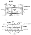
以下に、第2,3図を参照して連通部の別の構成について説明する。 Hereinafter, another configuration of the communication portion will be described with reference to FIGS.
第2図(a)は連通部の別の構成例を示すバッグの水平断面図であり、第2図(b)は第2図(a)のB−B線に沿う断面図である。 FIG. 2 (a) is a horizontal sectional view of a bag showing another configuration example of the communicating portion, and FIG. 2 (b) is a sectional view taken along line BB in FIG. 2 (a).
この第2図の乗員保護装置10Aにおいては、バッグ12内に、該バッグ12の直径方向の対向面同士を連結するように区画パネル16Aが設けられている。図示の通り、この区画パネル16Aは、左右方向(バッグ12の長手方向)に連続して延在するものであるが、その左右方向の大きさはバッグ12の左右方向の大きさよりも小さく、該区画パネル16Aの左右方向両端部は、バッグ12の左右方向両端側の内周面から所定距離離隔している。
In the occupant protection device 10A of FIG. 2, a partition panel 16A is provided in the
この区画パネル16Aの左右方向両端部とバッグ12の左右方向両端側の内周面との間の間隙が、それぞれ、該区画パネル16Aを挟んで下側に形成された第1の室18と上側に形成された第2の室20とを連通する連通部(ガス流通空間)36となっている。
The gaps between the left and right ends of the partition panel 16A and the inner peripheral surfaces of the
この実施の形態では、該第1の室18の左右方向中間付近にガス発生器14が配置されている。符号14aは、このガス発生器14の側周面に設けられたガス噴出口を示している。
In this embodiment, the
この乗員保護装置10Aのその他の構成は前述の第1図の乗員保護装置10と同様となっている。
Other configurations of the occupant protection device 10A are the same as those of the
このように構成された乗員保護装置10Aにあっては、ガス発生器14がガス噴出作動すると、該ガス発生器14から第1の室18内にガスが供給され、まず第1の室18が膨張する。この際、第1の室18内において、該ガス発生器14からのガスは該第1の室18の左右方向中間側から左右方向両端側に向って流れる。そして、このガスは、該左右方向両端側の各連通部36を介して第2の室20内に流入し、第2の室20を膨張させる。これにより、バッグ長手方向両端付近を含めてバッグ12全体が略々同時に膨張完了するようになる。
In the occupant protection device 10A configured as described above, when the
第3図(a)は連通部のさらに別の構成例を示すバッグの水平断面図であり、第3図(b)は第3図(a)のB−B線に沿う断面図である。 FIG. 3 (a) is a horizontal sectional view of a bag showing still another configuration example of the communicating portion, and FIG. 3 (b) is a sectional view taken along line BB of FIG. 3 (a).
この第3図の乗員保護装置10Bにおいては、バッグ12内に、左右方向の幅員が小さい複数枚(この実施の形態では3枚)の区画パネル16Bが設けられている。これらの区画パネル16Bは、互いに左右方向に所定の間隔をあけて多列に配設されている。各区画パネル16Bは、バッグ12の直径方向の対向面同士を連結している。このように複数枚の区画パネル16Bを左右方向に多列に配列することにより、バッグ12内が、それぞれ該バッグ12の左端から右端にかけて延在する第1の室18及び第2の室20の上下2室に区画されている。なお、左右方向両端側に配置された各区画パネル16Bとバッグ12の左右方向両端側の内周面との間にも所定の間隔があいている。
In the occupant protection device 10B of FIG. 3, a plurality of (three in this embodiment)
この実施の形態では、各区画パネル16B相互間の間隙並びに左右方向両端側の各区画パネル16Bとバッグ12の左右方向両端側の内周面との間の間隙が、それぞれ、該区画パネル16Bの配列体を挟んで下側に形成された第1の室18と上側に形成された第2の室20とを連通する連通部(ガス流通空間)38となっている。
In this embodiment, the gaps between the
この乗員保護装置10Bのその他の構成は前述の第1図の乗員保護装置10と同様となっている。
Other configurations of the passenger protection device 10B are the same as those of the
この乗員保護装置10Bにあっても、第1の室18内に配置されたガス発生器14からまず第1の室18内にガスが供給されて該第1の室18がバッグ12の左端から右端にかけて素早く膨張し、次いでこのガスが各連通部38を介して第2の室20に流入し、該第2の室20が全体的に素早く膨張する。
Even in this
本発明においては、1個の区画パネルが複数個の小片(小パネル)により構成されてもよい。第4図(a)はこのように構成された乗員保護装置10Cのバッグ部分の透視斜視図であり、第4図(b)は第4図(a)のB−B線に沿う断面図である。
In the present invention, one partition panel may be composed of a plurality of small pieces (small panels). FIG. 4 (a) is a perspective view of the bag portion of the
この乗員保護装置10Cにおいても、バッグ12内に、該バッグ12の直径方向対向面同士を連結するように区画パネル16Cが設けられている。符号40はこの区画パネル16Cの両端をバッグ内面に結合したシームを示している。この区画パネル16Cは、左右方向(バッグ12の長手方向)に連続して延在しており、この区画パネル16Cにより、該バッグ12の内部が、該バッグ12の左端から右端にかけてそれぞれ延在する第1の室18及び第2の室20の上下2室に区画されている。
Also in this
この実施の形態では、該区画パネル16Cに、その一方の長手方向側縁部の左右方向途中部分を切欠いた如き形状の連通部(切欠き)42が設けられており、この連通部42を介して、該区画パネル16Cの下側に形成された第1の室18と上側に形成された第2の室20とが連通している。
In this embodiment, the partition panel 16C is provided with a communication portion (notch) 42 having a shape in which a middle portion in the left-right direction of one edge in the longitudinal direction is cut out. Thus, the first chamber 18 formed on the lower side of the partition panel 16C communicates with the
区画パネル16Cは、この実施の形態では、3個の小パネル44,46,48を縫い合わせてなるものである。符号50はこれらの小パネル44,46,48同士を縫合したシームを示している。第4図(a)の通り、小パネル44は、区画パネル16Cのうち、該区画パネル16Cによるバッグ12内の対向面同士の連結方向における途中部分から一端側の領域を構成し、小パネル46,48は、該途中部分から他端側の領域を構成している。該小パネル46,48は、小パネル44の側辺に沿って、区画パネル16Cの長手方向(左右方向)一端側と他端側とにそれぞれ配置されている。これらの小パネル46,48同士は互いに離隔して配置されており、両者の間の間隙が前記連通部42となっている。
In this embodiment, the partition panel 16C is formed by sewing three
この乗員保護装置10Cのその他の構成は前述の第1図の乗員保護装置10と同様となっている。
Other configurations of the
前述の各実施の形態では、図示の通り、区画パネルは、バッグが膨張した状態においてシートパンの上面と平行に延在した姿勢となるように(即ち、前述の各実施の形態においては、区画パネルによるバッグ内の対向面同士の連結方向がシートパンの上面と平行方向となるように)配置されているが、区画パネルの配置はこれに限定されるものではない。 In each of the above-described embodiments, as illustrated, the partition panel has a posture extending in parallel with the upper surface of the seat pan when the bag is inflated (that is, in each of the above-described embodiments, the partition panel Although the connection direction of the opposing surfaces in the bag by a panel is arrange | positioned so that it may become a parallel direction with the upper surface of a sheet pan, arrangement | positioning of a division panel is not limited to this.
第5図及び第6図は、それぞれ、区画パネルの他の配置例を示す乗員保護装置の縦断面図である。 FIGS. 5 and 6 are longitudinal sectional views of an occupant protection device showing another arrangement example of the partition panel.
第5図の乗員保護装置10Dにおいては、区画パネル16Dは、バッグ12が膨張した状態において水平方向に延在した姿勢となるように(なお、第5,6図の実施の形態でも、前述の各実施の形態と同様、シートパン1の上面は、前方に向って上り勾配となるように延在している。)配置されている。
In the occupant protection device 10D of FIG. 5, the partition panel 16D is in a posture that extends in the horizontal direction when the
また、第6図の乗員保護装置10Eでは、区画パネル16Eは、バッグ12が膨張した状態において略上下方向に延在した姿勢となるように配置されている。この場合、該区画パネル16Eを挟んで前側(車両前方側)が第1の室18Eとなっており、後側(車両後方側)が第2の室20Eとなっている。この乗員から離隔した側の第1の室18E内にガス発生器14が配置されている。
In the occupant protection device 10E of FIG. 6, the partition panel 16E is disposed so as to extend substantially in the vertical direction when the
この乗員保護装置10Eにおいては、バッグ12が膨張するに当っては、ガス発生器14からまず第1の室18E内にガスが供給されて第1の室18Eが左右方向及び上下方向に膨張し、次いで、区画パネル16Eに設けられた連通部(図示略)を介して第2の室20Eにガスが流入し、該第2の室20Eが乗員側に向って膨張するようになる。
In this occupant protection device 10E, when the
これらの乗員保護装置10D,10Eのその他の構成も、それぞれ、前述の第1図の乗員保護装置10と同様となっている。
Other configurations of these occupant protection devices 10D and 10E are the same as those of the
第7図(a)はさらに別の区画パネルの配置例を示す乗員保護装置の縦断面図であり、第7図(b)は第7図(a)のB−B線に沿う断面図である。 FIG. 7 (a) is a longitudinal sectional view of an occupant protection device showing another example of the arrangement of the partition panels, and FIG. 7 (b) is a sectional view taken along the line BB of FIG. 7 (a). is there.
この第7図の乗員保護装置10Fでは、バッグ12の底面部内面に沿って左右方向に延在している棒状のガス発生器14の上方を前後方向に跨ぐように区画パネル16Fが配置され、その前端部及び後端部がそれぞれバッグ12の底面部の前側部分及び後側部分に結合されている。符号52はこの結合のシームを示している。
In the occupant protection device 10F of FIG. 7, the partition panel 16F is disposed so as to straddle the top of the rod-
即ち、この乗員保護装置10Fにおいては、バッグ12の底面部に沿って、該底面部と区画パネル16Fとによって囲まれた、左右方向に延在する筒状の第1の室18Fが形成されている。そして、このバッグ12内の残余の部分が第2の室20Fとなっている。
That is, in this occupant protection device 10F, a cylindrical
なお、この区画パネル16Fは左右方向(バッグ12の長手方向)に連続して延在するものであるが、第7図(b)に示すように、その左右方向の大きさはバッグ12の左右方向の大きさよりも小さく、その左右両端部はバッグ12の左右両端側の内面からそれぞれ離隔している。従って、この区画パネル16Fの左右両端部とバッグ12の左右両端側の内面との間が、それぞれ、第1の室18Fと第2の室20Fとを連通する連通部(通気空間)54となっている。
The partition panel 16F extends continuously in the left-right direction (longitudinal direction of the bag 12). However, as shown in FIG. It is smaller than the size in the direction, and its left and right ends are separated from the inner surfaces of the left and right ends of the
この乗員保護装置10Fのその他の構成は前述の第1図の乗員保護装置10と同様となっている。
Other configurations of the passenger protection device 10F are the same as those of the
このように構成された乗員保護装置10Fにあっては、第1の室18Fが左右方向に延在する筒状の空間となっているので、この第1の室18Fの制流作用により、ガス発生器14から該第1の室18F内に噴出したガスは左右方向に導かれるようになる。これにより、バッグ12の左右方向への膨張が一層素早いものとなる。
In the occupant protection device 10F configured as described above, the
前述の各実施の形態では、図示の通り、区画パネルはバッグの外殻を構成するパネルとは別体に設けられているが、バッグの外殻を構成するパネルと区画パネルとは一体に設けられてもよい。 In each of the above-described embodiments, as shown, the partition panel is provided separately from the panel constituting the outer shell of the bag, but the panel constituting the outer shell of the bag and the partition panel are provided integrally. May be.
第8〜11図は、それぞれ、バッグの外殻と区画パネルとを一体に構成した乗員保護装置の縦断面図である。 FIGS. 8 to 11 are longitudinal sectional views of an occupant protection device in which an outer shell of a bag and a partition panel are integrally formed.
第8図の乗員保護装置10Gにおいては、バッグ12Gは、上面パネル56と下面パネル58の2枚のパネルにより外殻が構成されている。この上面パネル56及び下面パネル58の前縁及び後縁からは、それぞれ、区画パネル16Gを構成する舌片状のパネル半体56a,56b及び58a,58bが突設されている。各パネル半体56a,56b,58a,58bは、各パネル56,58とそれぞれ一体に形成されたものである。
In the occupant protection device 10G of FIG. 8, the bag 12G has an outer shell composed of two panels, an upper panel 56 and a lower panel 58. From the front edge and the rear edge of the upper surface panel 56 and the lower surface panel 58, tongue-like panel halves 56a and 56b and 58a and 58b constituting the partition panel 16G are respectively projected. Each
この実施の形態では、各パネル半体56a,56b,58a,58bがバッグ内部側に折り込まれると共に、上面パネル56及び下面パネル58の前縁側のパネル半体56a,58a同士、並びに、該上面パネル56及び下面パネル58の後縁側のパネル半体56b,58b同士がそれぞれ2枚重ね状とされ、これら2枚重ね状のパネル半体の先端部同士が結合されることにより、バッグ12G内に区画パネル16Gが架設される。符号60はこの結合のシームを示している。
In this embodiment, the panel halves 56a, 56b, 58a, 58b are folded inside the bag, the panel halves 56a, 58a on the front edge side of the upper panel 56 and the lower panel 58, and the upper panel. 56 and the panel halves 56b, 58b on the rear edge side of the bottom panel 58 are overlapped with each other, and the front ends of the two panel halves are joined to each other so as to be partitioned in the bag 12G. A panel 16G is installed.
なお、これら2枚重ね状のパネル半体56a,58a同士及び56b,58b同士の基端部をそれぞれ通過しつつ上面パネル56及び下面パネル58の周縁部を周回するようにシーム62が延設されることにより、該上面パネル56と下面パネル58とが袋状に縫い合わされ、バッグ12Gの外殻が構成される。
The
第9図の乗員保護装置10Hにおいても、バッグ12Hは、上面パネル64と下面パネル66の2枚のパネルにより外殻が構成されている。この実施の形態では、該上面パネル64の前縁及び下面パネル66の後縁からそれぞれ区画パネル16Hを構成する舌片状のパネル半体64a及び66aが突設されている。 Also in the occupant protection device 10H of FIG. 9, the bag 12H has an outer shell composed of two panels, an upper panel 64 and a lower panel 66. In this embodiment, tongue-like panel halves 64a and 66a that project from the front edge of the upper panel 64 and the rear edge of the lower panel 66, respectively, that constitute the partition panel 16H are provided.
この実施の形態では、各パネル半体64a,66aがバッグ内部側に折り込まれると共に、各々の先端部同士が結合されることにより、バッグ12H内に区画パネル16Hが架設される。符号68はこの結合のシームを示している。
In this embodiment, the panel halves 64a and 66a are folded into the inside of the bag, and the front ends thereof are joined together, whereby the partition panel 16H is installed in the bag 12H.
なお、上面パネル64の後縁部をパネル半体66aの基端部に重ね合わせると共に下面パネル66の前縁部をパネル半体64aの基端部に重ね合わせ、これらの上面パネル64及び下面パネル66の周縁部を周回するようにシーム70が延設されることにより、該上面パネル64と下面パネル66とが袋状に縫い合わされ、バッグ12Hの外殻が構成される。
The rear edge of the upper panel 64 is overlapped with the base end of the
第10図の乗員保護装置10Jにおいても、バッグ12Jは、上面パネル72と下面パネル74の2枚のパネルにより外殻が構成されている。この実施の形態では、下面パネル74の後縁から該下面パネル74と一体に舌片状に区画パネル16Jが突設されている。 Also in the occupant protection device 10J of FIG. 10, the bag 12J has an outer shell composed of two panels, an upper panel 72 and a lower panel 74. In this embodiment, a partition panel 16J projects in a tongue-like shape integrally with the lower surface panel 74 from the rear edge of the lower surface panel 74.
この実施の形態では、該区画パネル16Jがバッグ内部側に折り込まれ、その先端部が上面パネル72及び下面パネル74の前縁部同士に結合されることにより、区画パネル16Jがバッグ12Jの内部に架設される。符号76はこの結合のシームを示している。
In this embodiment, the partition panel 16J is folded inside the bag, and the front ends of the partition panel 16J are joined to the front edges of the upper panel 72 and the lower panel 74, so that the partition panel 16J is placed inside the bag 12J. It will be erected.
なお、このシーム76は上面パネル72と下面パネル74の周縁部同士をも結合している。即ち、上面パネル72の後縁部を区画パネル16Jの基端部に重ね合わせると共に、該上面パネル72及び下面パネル74の前縁部同士と区画パネル16Jの先端部とを3枚重ね状とした状態にて、該上面パネル72及び下面パネル74の周縁部を周回するように該シーム76を延設することにより、バッグ12J内に区画パネル16Jが架設されると共に該上面パネル72と下面パネル74とが袋状に縫い合わされ、バッグ12Jの外殻が構成される。
The
第11図の乗員保護装置10Kにおいては、バッグ12Kは、底面パネル78と、乗員対向面パネル80と、前面パネル82の3枚のパネルから外殻が構成されている。符号84,86,88は、それぞれ、該底面パネル78と乗員対向面パネル80の側縁部同士、乗員対向面パネル80と前面パネル82の側縁部同士、及び前面パネル82と底面パネル78の側縁部同士を結合したシームを示している。
In the occupant protection device 10K of FIG. 11, the bag 12K has an outer shell made up of three panels: a bottom panel 78, an occupant facing panel 80, and a front panel 82.
この実施の形態では、該底面パネル78の乗員対向面パネル80側の側縁部と、前面パネル82の乗員対向面パネル80側の側縁部とから、区画パネル16Kを構成する舌片状のパネル半体90,92がそれぞれ突設されている。これらのパネル半体90,92がそれぞれバッグ内部に折り込まれ、各々の先端同士が結合されることにより、区画パネル16Kがバッグ12Kの内部に架設される。符号94はこの結合のシームを示している。
In this embodiment, a tongue-like shape constituting the partition panel 16K is formed from the side edge of the bottom panel 78 on the passenger facing surface panel 80 side and the side edge of the front panel 82 on the passenger facing surface panel 80 side.
なお、乗員対向面パネル80の底面パネル78側の側縁部はこのパネル半体90の基端部に重ね合わされてシーム84によりこれと結合され、乗員対向面パネル80の前面パネル82側の側縁部はパネル半体92の基端側に重ね合わされてシーム86によりこれと結合されている。
The side edge of the occupant-facing surface panel 80 on the bottom panel 78 side is overlapped with the base end portion of the
図示の通り、この実施の形態では、該区画パネル16Kは、バッグ12Kがシートパン1上で膨張した状態において略上下方向に延在した姿勢となるよう配置されており、この区画パネル16Kを挟んで前側に第1の室18Kが形成され、後側(乗員側)に第2の室20Kが形成されている。
As shown in the figure, in this embodiment, the partition panel 16K is disposed so as to extend in a substantially vertical direction when the bag 12K is inflated on the
上記の各実施の形態では、いずれもバッグ内が第1の室と他の1室(第2の室)との2室に区画されているが、本発明においては、第1の室の他に2個以上の室を形成してもよい。 In each of the above embodiments, the inside of the bag is divided into two chambers, a first chamber and another one chamber (second chamber). However, in the present invention, in addition to the first chamber, Two or more chambers may be formed.
第12図(a)はこのように構成された乗員保護装置10Lの斜視図であり、第12図(b)は第12図(a)のB−B線に沿う断面図である。 FIG. 12 (a) is a perspective view of the occupant protection device 10L configured as described above, and FIG. 12 (b) is a cross-sectional view taken along line BB in FIG. 12 (a).
この第12図の乗員保護装置10Lにおいては、バッグ12Lの内部空間は、左右方向に延在する区画パネル16LAによりバッグ下部側とバッグ上部側とに区画されると共に、該バッグ上部側が、バッグ12Lの長手方向中間付近に配置された区画パネル16LBにより、左右2室に区画されている。該区画パネル16LAの下側の空間が、該バッグ12Lの左端から右端にかけて延在する第1の室18Lとなっており、該区画パネル16LAの上側の空間のうち、区画パネル16LBを挟んで左半側及び右半側がそれぞれ第2の室20LL及び第3の室20LRとなっている。 In the occupant protection device 10L of FIG. 12, the internal space of the bag 12L is divided into a bag lower side and a bag upper side by a partition panel 16LA extending in the left-right direction. Are partitioned into two chambers on the left and right by a partition panel 16LB disposed near the middle in the longitudinal direction. The space below the partition panel 16LA is a first chamber 18L extending from the left end to the right end of the bag 12L. Of the space above the partition panel 16LA, the left side of the partition panel 16LB is left. The half side and the right half side are a second chamber 20LL and a third chamber 20LR, respectively.
なお、この実施の形態では、バッグ12Lは上面パネル96と下面パネル98とによって外殻が構成されており、区画パネル16LAは、その外周縁が、これらの上面パネル96及び下面パネル98の周縁部に対し全周にわたって縫合されている。符号100はこの縫合のシームを示している。また、この実施の形態では、該シーム100により上面パネル96と下面パネル98の周縁部同士も縫合され、袋状のバッグ外殻が構成されている。
In this embodiment, the bag 12L has an outer shell composed of an
符号102,104は、それぞれ、区画パネル16LBの下縁部及び上側周縁部をそれぞれ区画パネル16LA及び上面パネル96に縫合したシームを示している。
該区画パネル16LAの左半側及び右半側には、それぞれ、該第1の室18Lと第2の室20LL、並びに第1の室18Lと第3の室20LRを連通する連通部としての連通孔106,108が設けられている。
The left half side and the right half side of the partition panel 16LA communicate with each other as a communication portion that communicates the first chamber 18L and the second chamber 20LL, and the first chamber 18L and the third chamber 20LR, respectively.
なお、この実施の形態では第2の室20LLと第3の室20LRとは連通していないが、区画パネル16LBに連通孔等を設けてこれらを連通してもよい。 In this embodiment, the second chamber 20LL and the third chamber 20LR are not communicated with each other, but a communication hole or the like may be provided in the partition panel 16LB to communicate these.
この乗員保護装置10Lのその他の構成は前述の第1図の乗員保護装置10と同様となっている。
Other configurations of the passenger protection device 10L are the same as those of the
このように構成された乗員保護装置10Lにおいては、バッグ12Lが膨張する際には、バッグ12Lの左端から右端にかけて延在した第1の室18Lにまずガス発生器14からのガスが供給されて該第1の室18Lが膨張する。次いで、各連通孔106,108を介して第2の室20LL及び第3の室20LRにガスが流入して該第2の室20LL及び第3の室20LRがそれぞれ膨張する。
In the occupant protection device 10L configured in this way, when the bag 12L is inflated, the gas from the
この乗員保護装置10Lにあっては、乗員からバッグ上部側の各室20LL,20LRに大きな荷重が加えられた場合であっても、各室の内圧がそれぞれ増大し、上面パネル96が部分的に凹曲変形することが防止される。これにより、乗員の両脚を均等に受け止めることができる。
In this occupant protection device 10L, even when a large load is applied from the occupant to each of the chambers 20LL and 20LR on the upper side of the bag, the internal pressure of each chamber increases, and the
上記の各実施の形態ではガス発生器をバッグの内部に配置しているが、ガス発生器は、バッグの外部に配置されてもよい。第13図はこのように構成された乗員保護装置10Mの斜視図である。 In each of the above embodiments, the gas generator is arranged inside the bag, but the gas generator may be arranged outside the bag. FIG. 13 is a perspective view of the occupant protection device 10M configured as described above.
この第13図の乗員保護装置10Mにおいては、バッグ12Mの内部に、該バッグ12Mがシートパン(図示略)上で膨張した状態において略上下方向に延在した姿勢となるように区画パネル16Mが配置され、この区画パネル16Mを挟んで前側に第1の室18Mが形成されると共に、後側(乗員側)に第2の室20Mが形成されている。該区画パネル16Mには、これらの第1の室18Mと第2の室20Mとを連通する連通部としての連通孔110が左右方向に等間隔に複数個(この実施の形態では3個)配設されている。 In the occupant protection device 10M of FIG. 13, the partition panel 16M is placed inside the bag 12M so that the bag 12M extends in a substantially vertical direction when the bag 12M is inflated on a seat pan (not shown). The first chamber 18M is formed on the front side across the partition panel 16M, and the second chamber 20M is formed on the rear side (occupant side). In the partition panel 16M, a plurality of communication holes 110 (three in this embodiment) are arranged at equal intervals in the left-right direction as communication portions that communicate the first chamber 18M and the second chamber 20M. It is installed.
この実施の形態では、該バッグ12Mの長手方向の一端側に第1の室18M内に通じるガス導入口112が設けられており、このガス導入口112に接続されたパイプ114を介してガス発生器14Mから第1の室18Mにガスが供給されるようになっている。 In this embodiment, a gas inlet 112 leading to the inside of the first chamber 18M is provided on one end side in the longitudinal direction of the bag 12M, and gas is generated via a pipe 114 connected to the gas inlet 112. Gas is supplied from the vessel 14M to the first chamber 18M.
該ガス発生器14Mは、この実施の形態では、円筒形のケーシングを有しており、その一端側にガス噴出口(図示略)が設けられたタイプのものである。パイプ114は、一端側がこのガス発生器14Mのガス噴出口に接続され、他端側がバッグ12Mのガス導入口112に接続されている。 In this embodiment, the gas generator 14M has a cylindrical casing and is of a type in which a gas outlet (not shown) is provided on one end side thereof. One end of the pipe 114 is connected to the gas outlet of the gas generator 14M, and the other end is connected to the gas inlet 112 of the bag 12M.
なお、この実施の形態では、バッグ12Mの長手方向の両端部から耳状のバッグ取付片116が突設されており、各バッグ取付片116が各々のボルト挿通孔116aを介してシートパンにボルト留めされることにより、バッグ12Mがシートパンに固定される。
In this embodiment, ear-shaped
この乗員保護装置10Mにあっては、ガス発生器14Mがバッグ12Mの外部に配置されているので、バッグ12Mの折り畳み状態時における厚みが小さなものとなり、この乗員保護装置10Mを設置したことによるシートの座り心地の低下が防止ないし抑制される。 In this occupant protection device 10M, since the gas generator 14M is disposed outside the bag 12M, the thickness of the bag 12M when folded is small, and the seat is obtained by installing this occupant protection device 10M. A decrease in sitting comfort is prevented or suppressed.
第14図はバッグの別の構成例を示す縦断面図である。 FIG. 14 is a longitudinal sectional view showing another structural example of the bag.
この第14図の乗員保護装置10Nにおいては、バッグ12Nは、該バッグ12Nの外殻を構成する上面パネル12a及び下面パネル12bと、該バッグ12N内をシートパン側の第1の室18Nと座面側の第2の室20Nとに区画する区画パネル16Nの3枚のパネルからなる。該区画パネル16Nには、第1の室18Nと第2の室20Nとを連通する連通孔22Nが設けられている。
In the occupant protection device 10N shown in FIG. 14, the bag 12N includes an
このバッグ12Nを製作するに当っては、上面パネル12aと下面パネル12bとの間に区画パネル16Nを配置して3枚重ねにし、これら3枚のパネル12a,16N,12bの周縁部同士を縫合する。符号24Nは、この縫合のシームを示している。
In manufacturing the bag 12N, the partition panel 16N is disposed between the
なお、この縫合に際しては、これら3枚のパネル12a,16N,12bの周縁部同士を3枚重ねにした状態で平面縫いすればよく、きわめて簡単にバッグ12Nを製作することができる。
It should be noted that when sewing, it is only necessary to sew planes in a state where the three peripheral portions of the three
この乗員保護装置10Nのその他の構成は第1図の乗員保護装置10と同様であり、第14図において第1図と同一の符号は同一の部分を示している。
The other configuration of this occupant protection device 10N is the same as that of the
第15図(a)は別の実施の形態に係る乗員保護装置の斜視図であり、第15図(b)は第15図(a)のB−B線に沿う断面図である。 FIG. 15 (a) is a perspective view of an occupant protection device according to another embodiment, and FIG. 15 (b) is a cross-sectional view taken along the line BB of FIG. 15 (a).
この第15図の乗員保護装置10Pにおいては、シート(座席)の左右幅方向に延在したバッグ12の長手方向の中央付近に、該バッグ12を周方向に囲むバッグ包囲体120が設けられている。この実施の形態では、該バッグ包囲体120は、所定幅の幅広のシート状物を巻回し、その一端縁と他端縁とを縫合して筒状としたものである。符号122はこの縫合のシームを示している。
In the occupant protection device 10P of FIG. 15, a
このバッグ包囲体120の周長は、フリーな状態で膨張したバッグ12の該中央付近の周長よりも小さいものとなっている。
The circumferential length of the
このバッグ包囲体120を構成するシート状物は、該バッグ包囲体120の周方向に伸張しにくい、或いは全く伸張しない材質であることが好ましい。このシート状物は、布材や合成樹脂シート或いは合成樹脂メッシュシート等の比較的柔軟な材料からなるものであってもよく、金属板や金属メッシュ等の硬質な材料からなるものであってもよい。
The sheet-like material constituting the
なお、乗員保護装置10Pは、このバッグ包囲体120が設けられたこと以外は第1図の乗員保護装置10と同一構成となっている。即ち、バッグ12内にリテーナ28が配置されており、該リテーナ28の下面から突設されたスタッドボルト30が該バッグ12の下面を貫通してバッグ12の外部(下方)に延出している。この実施の形態では、該スタッドボルト30は、バッグ12を取り巻くバッグ包囲体120をも貫通している。このスタッドボルト30がシートパン1に差し通され、ナット34締めされることにより、バッグ包囲体120がバッグ12と共に該シートパン1に留め付けられている。
The occupant protection device 10P has the same configuration as the
かかる構成の乗員保護装置10Pにあっては、フリーな状態で膨張したバッグ12よりも周長が小さいバッグ包囲体120がバッグ12の長手方向の中央付近を囲んでいるため、バッグ12が膨張した場合には、バッグ12の該中央付近の大きさはバッグ包囲体120の周長に止まるようになる。これにより、バッグ12の該中央付近が過度に上方へ膨張することが防止されると共に、バッグ12の内圧が膨張開始後早期に高まって該バッグ12の長手方向の両端側まで素早く膨張するようになる。
In the occupant protection device 10P having such a configuration, since the
第16図はバッグ包囲体の別の構成例を示す縦断面図である。 FIG. 16 is a longitudinal sectional view showing another configuration example of the bag enclosure.
この第16図の乗員保護装置10P’においては、シート状物をバッグ12の外周に巻き付け、その両端縁をそれぞれバッグ12の下面から下方へ延出したスタッドボルト30に引っ掛けるようにして固定することにより、該バッグ12を囲むバッグ包囲体120’が設けられている。この乗員保護装置10P’のその他の構成は第15図の乗員保護装置10Pと同様となっている。
In the occupant protection device 10P ′ of FIG. 16, the sheet-like material is wound around the outer periphery of the
このバッグ包囲体の構成は図示のものに限定されない。上記の各実施の形態では、バッグ包囲体は幅広の筒状となっているが、幅の細いリング状としてもよい。また、バッグ包囲体は、バッグの長手方向の途中の1箇所(例えば中央付近)にのみ設けられてもよく、複数箇所に設けられてもよい。 The configuration of the bag enclosure is not limited to the illustrated one. In each of the above-described embodiments, the bag enclosure has a wide cylindrical shape, but may have a narrow ring shape. Moreover, the bag enclosure may be provided only at one place (for example, near the center) in the middle of the bag in the longitudinal direction, or may be provided at a plurality of places.
なお、第11図〜第13図の各実施の形態のように、バッグ内に、予め上下方向に延在する区画パネルが設けられ、該バッグの上面と下面とがこの区画パネルによって連結されている場合には、バッグ包囲体を設けなくとも、該バッグ包囲体を設けた場合と同様の作用効果が奏される。 In addition, like each embodiment of FIGS. 11-13, the division panel extended in an up-down direction previously is provided in the bag, and the upper surface and lower surface of this bag are connected by this division panel. In the case where the bag enclosure is not provided, the same effects as those obtained when the bag enclosure is provided can be obtained.
上記の各実施の形態はいずれも本発明の一例を示すものであり、本発明は上記の各実施の形態に限定されるものではない。 Each of the above embodiments shows an example of the present invention, and the present invention is not limited to each of the above embodiments.
1 シートパン
10,10A〜10P,10P’ 乗員保護装置
12,12G,12H,12J,12K,12L,12M,12N バッグ
14,14M ガス発生器
16,16A〜16N 区画パネル
18,18E,18F,18K,18L,18M,18N 第1の室
20,20E,20F,20K,20LL,20M,20N 第2の室
20LR 第3の室
22,22N,106,108,110 連通孔
36,38,42,54 連通部
120,120’ バッグ包囲体
1
Claims (7)
該バッグ内に、該左右幅方向に延在する区画パネルによって区画された複数の室が形成されており、
このうちの第1の室は該バッグの該左右幅方向の一端から他端にまで延在し、他の室は該第1の室に連通しており、
前記ガス発生器は、該第1の室にガスを供給するように設置されている乗員保護装置であって、
該バッグは、前記シートのシートパンの上側に配置されており、
該区画パネルは、該バッグ内を該シートパン側と乗員側とに区画するように配置され、該区画パネルのシート前方側及び後方側の両端部は、該バッグの該シート前方側及び後方側の内周面にそれぞれ結合されており、
該バッグ内は、該区画パネルよりも該シートパン側が該第1の室となっており、該区画パネルよりも乗員側が該他の室となっており、
該バッグのうち該第1の室の底面部分が該シートパンの上面に固定されており、
該区画パネルに、該第1の室と他の室とを連通するための連通部が設けられており、
該バッグは、該他の室からガスをバッグ外に流出させるベントホールを備えており、
該区画パネルは、該バッグが膨張した状態において、シート前方に向って上り勾配となるように延在していることを特徴とする乗員保護装置。 In an occupant protection device having a bag that extends in the left-right width direction of the seat and is inflatable so as to press the front portion of the seat cushion from below, and a gas generator that inflates the bag in a vehicle emergency,
A plurality of chambers defined by partition panels extending in the left-right width direction are formed in the bag,
Of these, the first chamber extends from one end to the other end in the lateral width direction of the bag, and the other chamber communicates with the first chamber.
The gas generator is an occupant protection device installed to supply gas to the first chamber,
The bag is disposed above the seat pan of the sheet,
The partition panel is disposed so as to partition the inside of the bag into the seat pan side and the occupant side, and both end portions on the seat front side and the rear side of the partition panel are the seat front side and the rear side of the bag. Are respectively connected to the inner peripheral surface of
In the bag, the seat pan side of the compartment panel is the first chamber, the passenger side of the compartment panel is the other chamber,
The bottom portion of the first chamber of the bag is fixed to the upper surface of the seat pan,
The partition panel is provided with a communication portion for communicating the first chamber with another chamber,
The bag includes a vent hole that allows gas to flow out of the bag from the other chamber ,
The occupant protection device , wherein the partition panel extends so as to rise upward toward the front of the seat when the bag is inflated .
該バッグ内は、該左右幅方向に延在する区画パネルによって第1の室と他の室とに区画されており、
該他の室は該第1の室に連通しており、
前記ガス発生器は、該第1の室にガスを供給するように設置されている乗員保護装置であって、
該バッグは、前記シートのシートパンの上側に配置されており、
該区画パネルは、該バッグ内を該シートパン側と乗員側とに区画するように配置され、該区画パネルのシート前方側及び後方側の両端部は、該バッグの該シート前方側及び後方側の内周面にそれぞれ結合されており、
該バッグ内は、該区画パネルよりも該シートパン側が該第1の室となっており、該区画パネルよりも乗員側が該他の室となっており、
該バッグのうち該第1の室の底面部分が該シートパンの上面に固定されており、
該区画パネルの該左右幅方向の大きさは、該バッグの膨張時の該左右幅方向の大きさよりも小さく、該区画パネルの該左右幅方向の両端部は、該バッグの該左右幅方向の両端側の内周面から所定距離離隔しており、
該区画パネルの該左右幅方向の両端部と、該バッグの該左右幅方向の両端側の内周面との間の間隙は、該第1の室と他の室とを連通する連通部となっており、
該バッグは、該他の室からガスをバッグ外に流出させるベントホールを備えており、
該区画パネルは、該バッグが膨張した状態において、シート前方に向って上り勾配となるように延在していることを特徴とする乗員保護装置。 In an occupant protection device having a bag that extends in the left-right width direction of the seat and is inflatable so as to press the front portion of the seat cushion from below, and a gas generator that inflates the bag in a vehicle emergency,
The inside of the bag is partitioned into a first chamber and another chamber by a partition panel extending in the left-right width direction,
The other chamber communicates with the first chamber;
The gas generator is an occupant protection device installed to supply gas to the first chamber,
The bag is disposed above the seat pan of the sheet,
The partition panel is disposed so as to partition the inside of the bag into the seat pan side and the occupant side, and both end portions on the seat front side and the rear side of the partition panel are the seat front side and the rear side of the bag. Are respectively connected to the inner peripheral surface of
In the bag, the seat pan side of the compartment panel is the first chamber, the passenger side of the compartment panel is the other chamber,
The bottom portion of the first chamber of the bag is fixed to the upper surface of the seat pan,
The size in the left-right width direction of the partition panel is smaller than the size in the left-right width direction when the bag is inflated, and both end portions in the left-right width direction of the partition panel are in the left-right width direction of the bag. It is separated from the inner peripheral surface of both ends by a predetermined distance,
The gap between the both end portions of the partition panel in the left-right width direction and the inner peripheral surface of the bag at both end sides in the left-right width direction is a communication portion that communicates the first chamber with another chamber. And
The bag includes a vent hole that allows gas to flow out of the bag from the other chamber ,
The occupant protection device , wherein the partition panel extends so as to rise upward toward the front of the seat when the bag is inflated .
該バッグ内は、該左右幅方向に延在する区画パネルによって第1の室と他の室とに区画されており、
該他の室は該第1の室に連通しており、
前記ガス発生器は、該第1の室にガスを供給するように設置されている乗員保護装置であって、
該バッグは、前記シートのシートパンの上側に配置されており、
該区画パネルは、該バッグ内を該シートパン側と乗員側とに区画するように配置され、該区画パネルのシート前方側及び後方側の両端部は、該バッグの該シート前方側及び後方側の内周面にそれぞれ結合されており、
該バッグ内は、該区画パネルよりも該シートパン側が該第1の室となっており、該区画パネルよりも乗員側が該他の室となっており、
該バッグのうち該第1の室の底面部分が該シートパンの上面に固定されており、
該区画パネルの該左右幅方向の大きさは、該バッグの膨張時の該左右幅方向の大きさよりも小さく、該バッグ内には、該区画パネルが複数枚、該左右幅方向に所定の間隔をあけて多列に配設されており、且つ該左右幅方向の両端側に配置された各区画パネルは、該バッグの該左右幅方向の両端側の内周面から所定距離離隔して配置されており、
各区画パネル相互間の間隙、並びに該左右幅方向の両端側の各区画パネルと該バッグの該左右幅方向の両端側の内周面との間の間隙が、それぞれ、該第1の室と他の室とを連通する連通部となっており、
該バッグは、該他の室からガスをバッグ外に流出させるベントホールを備えており、
該区画パネルは、該バッグが膨張した状態において、シート前方に向って上り勾配となるように延在していることを特徴とする乗員保護装置。 In an occupant protection device having a bag that extends in the left-right width direction of the seat and is inflatable so as to press the front portion of the seat cushion from below, and a gas generator that inflates the bag in a vehicle emergency,
The inside of the bag is partitioned into a first chamber and another chamber by a partition panel extending in the left-right width direction,
The other chamber communicates with the first chamber;
The gas generator is an occupant protection device installed to supply gas to the first chamber,
The bag is disposed above the seat pan of the sheet,
The partition panel is disposed so as to partition the inside of the bag into the seat pan side and the occupant side, and both end portions on the seat front side and the rear side of the partition panel are the seat front side and the rear side of the bag. Are respectively connected to the inner peripheral surface of
In the bag, the seat pan side of the compartment panel is the first chamber, the passenger side of the compartment panel is the other chamber,
The bottom portion of the first chamber of the bag is fixed to the upper surface of the seat pan,
The size of the partition panel in the left-right width direction is smaller than the size in the left-right width direction when the bag is inflated, and a plurality of the partition panels are disposed in the bag at predetermined intervals in the left-right width direction. The partition panels that are arranged in multiple rows with gaps therebetween and arranged at both ends in the left-right width direction are arranged at a predetermined distance from the inner peripheral surfaces of both ends in the left-right width direction of the bag. Has been
A gap between the partition panels and a gap between each partition panel on both ends in the left-right width direction and inner peripheral surfaces on both ends in the left-right width direction of the bag, respectively, It is a communication part that communicates with other rooms,
The bag includes a vent hole that allows gas to flow out of the bag from the other chamber ,
The occupant protection device , wherein the partition panel extends so as to rise upward toward the front of the seat when the bag is inflated .
該バッグ内に、該左右幅方向に延在する区画パネルによって区画された複数の室が形成されており、A plurality of chambers defined by partition panels extending in the left-right width direction are formed in the bag,
このうちの第1の室は該バッグの該左右幅方向の一端から他端にまで延在し、他の室は該第1の室に連通しており、Of these, the first chamber extends from one end to the other end in the lateral width direction of the bag, and the other chamber communicates with the first chamber.
前記ガス発生器は、該第1の室にガスを供給するように設置されている乗員保護装置であって、The gas generator is an occupant protection device installed to supply gas to the first chamber,
該バッグは、前記シートのシートパンの上側に配置されており、The bag is disposed above the seat pan of the sheet,
該区画パネルは、該バッグ内を該シートパン側と乗員側とに区画するように配置され、該区画パネルのシート前方側及び後方側の両端部は、該バッグの該シート前方側及び後方側の内周面にそれぞれ結合されており、The partition panel is disposed so as to partition the inside of the bag into the seat pan side and the occupant side, and both end portions on the seat front side and the rear side of the partition panel are the seat front side and the rear side of the bag. Are respectively connected to the inner peripheral surface of
該バッグ内は、該区画パネルよりも該シートパン側が該第1の室となっており、該区画パネルよりも乗員側が該他の室となっており、In the bag, the seat pan side is the first chamber with respect to the partition panel, and the passenger side is the other chamber with respect to the partition panel,
該バッグのうち該第1の室の底面部分が該シートパンの上面に固定されており、The bottom portion of the first chamber of the bag is fixed to the upper surface of the seat pan,
該区画パネルに、該第1の室と他の室とを連通するための連通部が設けられており、The partition panel is provided with a communication portion for communicating the first chamber with another chamber,
該バッグは、該他の室からガスをバッグ外に流出させるベントホールを備えており、The bag includes a vent hole that allows gas to flow out of the bag from the other chamber,
該区画パネルは、該バッグが膨張した状態において、水平方向に延在していることを特徴とする乗員保護装置。The occupant protection device according to claim 1, wherein the partition panel extends in a horizontal direction when the bag is inflated.
該バッグ内は、該左右幅方向に延在する区画パネルによって第1の室と他の室とに区画されており、The inside of the bag is partitioned into a first chamber and another chamber by a partition panel extending in the left-right width direction,
該他の室は該第1の室に連通しており、The other chamber communicates with the first chamber;
前記ガス発生器は、該第1の室にガスを供給するように設置されている乗員保護装置であって、The gas generator is an occupant protection device installed to supply gas to the first chamber,
該バッグは、前記シートのシートパンの上側に配置されており、The bag is disposed above the seat pan of the sheet,
該区画パネルは、該バッグ内を該シートパン側と乗員側とに区画するように配置され、該区画パネルのシート前方側及び後方側の両端部は、該バッグの該シート前方側及び後方側の内周面にそれぞれ結合されており、The partition panel is disposed so as to partition the inside of the bag into the seat pan side and the occupant side, and both end portions on the seat front side and the rear side of the partition panel are the seat front side and the rear side of the bag. Are respectively connected to the inner peripheral surface of
該バッグ内は、該区画パネルよりも該シートパン側が該第1の室となっており、該区画パネルよりも乗員側が該他の室となっており、In the bag, the seat pan side of the compartment panel is the first chamber, the passenger side of the compartment panel is the other chamber,
該バッグのうち該第1の室の底面部分が該シートパンの上面に固定されており、The bottom portion of the first chamber of the bag is fixed to the upper surface of the seat pan,
該区画パネルの該左右幅方向の大きさは、該バッグの膨張時の該左右幅方向の大きさよりも小さく、該区画パネルの該左右幅方向の両端部は、該バッグの該左右幅方向の両端側の内周面から所定距離離隔しており、The size in the left-right width direction of the partition panel is smaller than the size in the left-right width direction when the bag is inflated, and both end portions in the left-right width direction of the partition panel are in the left-right width direction of the bag. It is separated from the inner peripheral surface of both ends by a predetermined distance,
該区画パネルの該左右幅方向の両端部と、該バッグの該左右幅方向の両端側の内周面との間の間隙は、該第1の室と他の室とを連通する連通部となっており、The gap between the both end portions of the partition panel in the left-right width direction and the inner peripheral surface of the bag at both end sides in the left-right width direction is a communication portion that communicates the first chamber with another chamber. And
該バッグは、該他の室からガスをバッグ外に流出させるベントホールを備えており、The bag includes a vent hole that allows gas to flow out of the bag from the other chamber,
該区画パネルは、該バッグが膨張した状態において、水平方向に延在していることを特徴とする乗員保護装置。The occupant protection device according to claim 1, wherein the partition panel extends in a horizontal direction when the bag is inflated.
該バッグ内は、該左右幅方向に延在する区画パネルによって第1の室と他の室とに区画されており、The inside of the bag is partitioned into a first chamber and another chamber by a partition panel extending in the left-right width direction,
該他の室は該第1の室に連通しており、The other chamber communicates with the first chamber;
前記ガス発生器は、該第1の室にガスを供給するように設置されている乗員保護装置であって、The gas generator is an occupant protection device installed to supply gas to the first chamber,
該バッグは、前記シートのシートパンの上側に配置されており、The bag is disposed above the seat pan of the sheet,
該区画パネルは、該バッグ内を該シートパン側と乗員側とに区画するように配置され、該区画パネルのシート前方側及び後方側の両端部は、該バッグの該シート前方側及び後方側の内周面にそれぞれ結合されており、The partition panel is disposed so as to partition the inside of the bag into the seat pan side and the occupant side, and both end portions on the seat front side and the rear side of the partition panel are the seat front side and the rear side of the bag. Are respectively connected to the inner peripheral surface of
該バッグ内は、該区画パネルよりも該シートパン側が該第1の室となっており、該区画パネルよりも乗員側が該他の室となっており、In the bag, the seat pan side is the first chamber with respect to the partition panel, and the passenger side is the other chamber with respect to the partition panel,
該バッグのうち該第1の室の底面部分が該シートパンの上面に固定されており、The bottom portion of the first chamber of the bag is fixed to the upper surface of the seat pan,
該区画パネルの該左右幅方向の大きさは、該バッグの膨張時の該左右幅方向の大きさよりも小さく、該バッグ内には、該区画パネルが複数枚、該左右幅方向に所定の間隔をあけて多列に配設されており、且つ該左右幅方向の両端側に配置された各区画パネルは、該バッグの該左右幅方向の両端側の内周面から所定距離離隔して配置されており、The size of the partition panel in the left-right width direction is smaller than the size in the left-right width direction when the bag is inflated, and a plurality of the partition panels are disposed in the bag at predetermined intervals in the left-right width direction. The partition panels that are arranged in multiple rows with gaps therebetween and arranged at both ends in the left-right width direction are arranged at a predetermined distance from the inner peripheral surfaces of both ends in the left-right width direction of the bag. Has been
各区画パネル相互間の間隙、並びに該左右幅方向の両端側の各区画パネルと該バッグの該左右幅方向の両端側の内周面との間の間隙が、それぞれ、該第1の室と他の室とを連通する連通部となっており、The gap between the partition panels and the gap between the partition panels on both ends in the left-right width direction and the inner peripheral surfaces on both ends in the left-right width direction of the bag, respectively, It is a communication part that communicates with other rooms,
該バッグは、該他の室からガスをバッグ外に流出させるベントホールを備えており、The bag includes a vent hole that allows gas to flow out of the bag from the other chamber,
該区画パネルは、該バッグが膨張した状態において、水平方向に延在していることを特徴とする乗員保護装置。The occupant protection device according to claim 1, wherein the partition panel extends in a horizontal direction when the bag is inflated.
該バッグ内に、該左右幅方向に延在する区画パネルによって区画された複数の室が形成されており、
このうちの第1の室は該バッグの該左右幅方向の一端から他端にまで延在し、他の室は該第1の室に連通しており、
前記ガス発生器は、該第1の室にガスを供給するように設置されている乗員保護装置であって、
該バッグは、前記シートのシートパンの上側に配置されており、
該区画パネルは、該バッグ内をシート前方側とシート後方側とに区画するように配置され、該区画パネルの上側及び下側の両端部は、該バッグの上側及び下側の内周面にそれぞれ結合されており、
該バッグ内は、該区画パネルよりも該前方側が該第1の室となっており、該区画パネルよりも該後方側が該他の室となっており、
該バッグのうち該区画パネルの前記下側端部よりも該第1の室側の底面部分が該シートパンの上面に固定されており、
該区画パネルに、該第1の室と他の室とを連通するための連通部が設けられており、
該バッグは、該他の室からガスをバッグ外に流出させるベントホールを備えており、
該シートパンの上面は、シート前方に向って上り勾配となるように延在していることを特徴とする乗員保護装置。 In an occupant protection device having a bag that extends in the left-right width direction of the seat and is inflatable so as to press the front portion of the seat cushion from below, and a gas generator that inflates the bag in a vehicle emergency,
A plurality of chambers defined by partition panels extending in the left-right width direction are formed in the bag,
Of these, the first chamber extends from one end to the other end in the lateral width direction of the bag, and the other chamber communicates with the first chamber.
The gas generator is an occupant protection device installed to supply gas to the first chamber,
The bag is disposed above the seat pan of the sheet,
The partition panel is disposed so as to partition the inside of the bag into a seat front side and a seat rear side, and both upper and lower end portions of the partition panel are on the upper and lower inner peripheral surfaces of the bag. Each is connected,
In the bag, the front side of the compartment panel is the first chamber, the rear side of the compartment panel is the other chamber,
The bottom part of the first chamber side of the bag is fixed to the upper surface of the seat pan from the lower end of the partition panel ,
The partition panel is provided with a communication portion for communicating the first chamber with another chamber,
The bag includes a vent hole that allows gas to flow out of the bag from the other chamber ,
The occupant protection device according to claim 1, wherein an upper surface of the seat pan extends upward toward the front of the seat .
Priority Applications (5)
| Application Number | Priority Date | Filing Date | Title |
|---|---|---|---|
| JP2004373959A JP4674468B2 (en) | 2004-02-10 | 2004-12-24 | Crew protection device |
| EP05002326A EP1564082B1 (en) | 2004-02-10 | 2005-02-03 | Occupant protection system |
| DE602005004043T DE602005004043T2 (en) | 2004-02-10 | 2005-02-03 | Occupant protection system |
| CNB2005100078613A CN100482500C (en) | 2004-02-10 | 2005-02-06 | Occupant protection system |
| US11/055,347 US7549674B2 (en) | 2004-02-10 | 2005-02-10 | Occupant protection system |
Applications Claiming Priority (2)
| Application Number | Priority Date | Filing Date | Title |
|---|---|---|---|
| JP2004033701 | 2004-02-10 | ||
| JP2004373959A JP4674468B2 (en) | 2004-02-10 | 2004-12-24 | Crew protection device |
Publications (3)
| Publication Number | Publication Date |
|---|---|
| JP2005255148A JP2005255148A (en) | 2005-09-22 |
| JP2005255148A5 JP2005255148A5 (en) | 2008-01-10 |
| JP4674468B2 true JP4674468B2 (en) | 2011-04-20 |
Family
ID=34703361
Family Applications (1)
| Application Number | Title | Priority Date | Filing Date |
|---|---|---|---|
| JP2004373959A Expired - Fee Related JP4674468B2 (en) | 2004-02-10 | 2004-12-24 | Crew protection device |
Country Status (5)
| Country | Link |
|---|---|
| US (1) | US7549674B2 (en) |
| EP (1) | EP1564082B1 (en) |
| JP (1) | JP4674468B2 (en) |
| CN (1) | CN100482500C (en) |
| DE (1) | DE602005004043T2 (en) |
Families Citing this family (43)
| Publication number | Priority date | Publication date | Assignee | Title |
|---|---|---|---|---|
| DE10303901A1 (en) * | 2003-01-31 | 2004-11-11 | Trw Occupant Restraint Systems Gmbh & Co. Kg | Airbag for a side impact protection device |
| JP4269826B2 (en) * | 2003-03-12 | 2009-05-27 | タカタ株式会社 | Crew protection device |
| JP4581812B2 (en) * | 2003-09-30 | 2010-11-17 | タカタ株式会社 | Crew protection device |
| JP4775111B2 (en) * | 2005-05-25 | 2011-09-21 | タカタ株式会社 | Crew protection device |
| JP4646746B2 (en) * | 2005-09-05 | 2011-03-09 | ダイハツ工業株式会社 | Automotive seat |
| JP4371274B2 (en) * | 2005-10-06 | 2009-11-25 | タカタ株式会社 | Airbag device |
| JP4802659B2 (en) | 2005-10-28 | 2011-10-26 | タカタ株式会社 | Crew restraint system |
| JP5078248B2 (en) * | 2005-10-28 | 2012-11-21 | タカタ株式会社 | Crew restraint system |
| JP4857713B2 (en) * | 2005-10-28 | 2012-01-18 | タカタ株式会社 | Crew restraint system |
| JP2007118816A (en) * | 2005-10-28 | 2007-05-17 | Takata Corp | Occupant restraint system |
| JP2007118817A (en) | 2005-10-28 | 2007-05-17 | Takata Corp | Occupant restraining device |
| JP2007131104A (en) * | 2005-11-09 | 2007-05-31 | Takata Corp | Occupant restraining device |
| DE602006014787D1 (en) * | 2005-12-01 | 2010-07-22 | Toyoda Gosei Kk | Passenger protection device |
| JP4609307B2 (en) * | 2005-12-21 | 2011-01-12 | 豊田合成株式会社 | Crew protection device |
| JP4193854B2 (en) * | 2006-02-16 | 2008-12-10 | トヨタ自動車株式会社 | Airbag device for vehicle |
| DE102006011105B4 (en) * | 2006-03-08 | 2010-09-16 | Autoliv Development Ab | Safety arrangement in a vehicle seat |
| JP2007276567A (en) * | 2006-04-04 | 2007-10-25 | Takata Corp | Occupant restraint system and vehicle seat |
| DE102006023272B4 (en) * | 2006-05-18 | 2009-12-31 | Autoliv Development Ab | Airbag unit |
| JP4818845B2 (en) * | 2006-08-09 | 2011-11-16 | 本田技研工業株式会社 | Airbag device |
| US20080088119A1 (en) * | 2006-10-13 | 2008-04-17 | Yoshiki Murakami | Passenger constraining apparatus |
| US20080252054A1 (en) * | 2007-04-16 | 2008-10-16 | Hyundai Mobis Co., Ltd. | Air bag cushion |
| EP2008879B1 (en) * | 2007-06-29 | 2012-06-27 | Dalphi Metal España, S.A. | Three-chamber adaptive side airbag |
| DE102007030846B4 (en) * | 2007-07-03 | 2014-08-28 | Autoliv Development Ab | Airbag module |
| KR101000260B1 (en) * | 2007-12-13 | 2010-12-10 | 현대자동차주식회사 | Structure of Airbag Cushion with Multi Chamber |
| JP5245707B2 (en) * | 2008-10-14 | 2013-07-24 | 豊田合成株式会社 | Airbag device |
| US9260192B2 (en) | 2009-07-27 | 2016-02-16 | Textron Innovations Inc. | Active vent and re-inflation system for a crash attentuation airbag |
| JP5463199B2 (en) * | 2010-05-14 | 2014-04-09 | 芦森工業株式会社 | Airbag device |
| JP2012016970A (en) * | 2010-07-06 | 2012-01-26 | Toyota Motor Corp | Vehicular seat built in with cushion airbag device |
| JP2012091559A (en) * | 2010-10-25 | 2012-05-17 | Nippon Plast Co Ltd | Airbag |
| CA2828084C (en) * | 2011-02-23 | 2018-05-15 | Bell Helicopter Textron Inc. | High efficiency external airbag for crash attenuation |
| CN102806883B (en) * | 2011-06-02 | 2015-06-24 | 比亚迪股份有限公司 | Safety air cushion of seat |
| US8523220B1 (en) | 2012-03-19 | 2013-09-03 | Amsafe, Inc. | Structure mounted airbag assemblies and associated systems and methods |
| JP5958129B2 (en) * | 2012-07-12 | 2016-07-27 | 豊田合成株式会社 | Seat cushion airbag device |
| CN103465860A (en) * | 2013-08-16 | 2013-12-25 | 浙江吉利汽车研究院有限公司 | Side air sag |
| EP3045355B1 (en) | 2015-01-14 | 2017-08-23 | Ford Global Technologies, LLC | Vehicle seat having an airbag module which is arranged in a seat portion |
| US9944245B2 (en) | 2015-03-28 | 2018-04-17 | Amsafe, Inc. | Extending pass-through airbag occupant restraint systems, and associated systems and methods |
| CN107428308A (en) | 2015-04-11 | 2017-12-01 | Am-安全公司 | Active air bags system |
| US10604259B2 (en) | 2016-01-20 | 2020-03-31 | Amsafe, Inc. | Occupant restraint systems having extending restraints, and associated systems and methods |
| CN107826004A (en) * | 2017-12-08 | 2018-03-23 | 清华大学苏州汽车研究院(相城) | A kind of lateral side protection and child safety seat for child safety seat |
| CN109334605B (en) * | 2018-09-10 | 2021-07-20 | 江苏大学 | Back row built-in safety airbag and control method thereof |
| JP7056508B2 (en) * | 2018-10-19 | 2022-04-19 | 豊田合成株式会社 | Vehicle occupant protection device |
| KR102593520B1 (en) * | 2018-11-12 | 2023-10-24 | 현대모비스 주식회사 | Behavior control airbag apparatus |
| EP4183638A1 (en) | 2020-07-14 | 2023-05-24 | Autoliv Development AB | Occupant protection device |
Citations (8)
| Publication number | Priority date | Publication date | Assignee | Title |
|---|---|---|---|---|
| JPH02141233U (en) * | 1989-04-28 | 1990-11-27 | ||
| JP2000255369A (en) * | 1999-03-03 | 2000-09-19 | Nippon Plast Co Ltd | Air bag device |
| JP2001247010A (en) * | 1999-12-28 | 2001-09-11 | Takata Corp | Occupant protective device |
| JP2002079862A (en) * | 2000-09-06 | 2002-03-19 | Toyoda Gosei Co Ltd | Bench seat for vehicle |
| JP2003306116A (en) * | 2002-04-15 | 2003-10-28 | Takata Corp | Occupant leg portion protecting device |
| DE202004002874U1 (en) * | 2004-02-25 | 2004-07-08 | Trw Automotive Gmbh | Car seat has air bag under seat cushion which inflates to wedge shape and raises its front edge, locking strips mounted inside bag holding it in shape |
| US20040178616A1 (en) * | 2003-03-12 | 2004-09-16 | Takata Corporation | Occupant protection system |
| JP2004338514A (en) * | 2003-05-14 | 2004-12-02 | Autoliv Kk | Inflator bag, and waist restraint system using the inflator bag |
Family Cites Families (25)
| Publication number | Priority date | Publication date | Assignee | Title |
|---|---|---|---|---|
| US4262931A (en) * | 1979-09-18 | 1981-04-21 | Ford Motor Company | Air bag restraint system |
| US4920591A (en) * | 1985-07-16 | 1990-05-01 | Hiroshi Sekido | Air support for chair and method for manufacturing chair utilizing the air support |
| US5082326A (en) * | 1989-04-28 | 1992-01-21 | Okamoto Industries, Inc. | Vehicle seat with automatic adjustment mechanisms utilizing inflatable air bags |
| JPH05229378A (en) | 1992-02-20 | 1993-09-07 | Toyota Motor Corp | Vehicle seat |
| JP2731324B2 (en) * | 1992-06-17 | 1998-03-25 | 株式会社東海理化電機製作所 | Air bag device bag and method of manufacturing bag |
| US5967551A (en) * | 1992-12-18 | 1999-10-19 | Autoliv Asp, Inc. | Reduced airbag deployment skewness with non-symmetric gas output inflators |
| JP3266983B2 (en) * | 1993-06-07 | 2002-03-18 | タカタ株式会社 | Vehicle airbag device |
| US5848805A (en) * | 1996-03-29 | 1998-12-15 | Toyo Tire & Rubber Co., Ltd. | Bag for an airbag for a vehicle |
| JP3285129B2 (en) * | 1997-01-31 | 2002-05-27 | ジョンソン コントロールズ オートモーティブ システムズ株式会社 | Vehicle seat |
| US5845935A (en) * | 1997-03-07 | 1998-12-08 | Morton International, Inc. | Side airbag module |
| JPH10329633A (en) * | 1997-05-30 | 1998-12-15 | Toyota Motor Corp | Chest-head integrated air bag device |
| US5899490A (en) * | 1997-06-13 | 1999-05-04 | Breed Automotive Technology, Inc. | Method of folding an air bag |
| DE29711679U1 (en) * | 1997-07-03 | 1997-10-30 | Trw Repa Gmbh | Airbag module |
| US6089599A (en) * | 1998-09-10 | 2000-07-18 | Breed Automotive Technology, Inc. | Baffled air bag |
| JP3900765B2 (en) * | 1999-12-08 | 2007-04-04 | タカタ株式会社 | Airbag device |
| EP1122134B1 (en) * | 2000-02-01 | 2005-02-16 | Delphi Automotive Systems Sungwoo Co., Ltd. | Side airbag system and method for manufacturing the same |
| JP4608072B2 (en) * | 2000-02-25 | 2011-01-05 | タカタ株式会社 | Airbag device |
| JP2002079863A (en) | 2000-09-06 | 2002-03-19 | Toyoda Gosei Co Ltd | Vehicle seat |
| JP4239387B2 (en) | 2000-09-06 | 2009-03-18 | 豊田合成株式会社 | Vehicle seat |
| JP2002145002A (en) | 2000-11-15 | 2002-05-22 | Toyoda Gosei Co Ltd | Occupant crash protection device |
| JP3687602B2 (en) * | 2001-12-10 | 2005-08-24 | トヨタ自動車株式会社 | Vehicle occupant knee protection device |
| JP3911189B2 (en) | 2002-04-23 | 2007-05-09 | 本田技研工業株式会社 | Air belt device |
| JP2004009798A (en) * | 2002-06-04 | 2004-01-15 | Takata Corp | Occupant crash protection device |
| AU2003252264A1 (en) * | 2002-07-25 | 2004-02-16 | Autoliv Development Ab | Inflator bag for occupant restraint device and method of manufacturing the inflator bag |
| DE10301462B3 (en) * | 2003-01-16 | 2004-08-05 | Breed Automotive Technology, Inc., Lakeland | Airbag module for automobile has free ends of gas bag bent transverse to its longitudinal direction for providing lugs inserted through gas bag fixing devices |
-
2004
- 2004-12-24 JP JP2004373959A patent/JP4674468B2/en not_active Expired - Fee Related
-
2005
- 2005-02-03 EP EP05002326A patent/EP1564082B1/en not_active Expired - Fee Related
- 2005-02-03 DE DE602005004043T patent/DE602005004043T2/en active Active
- 2005-02-06 CN CNB2005100078613A patent/CN100482500C/en not_active Expired - Fee Related
- 2005-02-10 US US11/055,347 patent/US7549674B2/en not_active Expired - Fee Related
Patent Citations (8)
| Publication number | Priority date | Publication date | Assignee | Title |
|---|---|---|---|---|
| JPH02141233U (en) * | 1989-04-28 | 1990-11-27 | ||
| JP2000255369A (en) * | 1999-03-03 | 2000-09-19 | Nippon Plast Co Ltd | Air bag device |
| JP2001247010A (en) * | 1999-12-28 | 2001-09-11 | Takata Corp | Occupant protective device |
| JP2002079862A (en) * | 2000-09-06 | 2002-03-19 | Toyoda Gosei Co Ltd | Bench seat for vehicle |
| JP2003306116A (en) * | 2002-04-15 | 2003-10-28 | Takata Corp | Occupant leg portion protecting device |
| US20040178616A1 (en) * | 2003-03-12 | 2004-09-16 | Takata Corporation | Occupant protection system |
| JP2004338514A (en) * | 2003-05-14 | 2004-12-02 | Autoliv Kk | Inflator bag, and waist restraint system using the inflator bag |
| DE202004002874U1 (en) * | 2004-02-25 | 2004-07-08 | Trw Automotive Gmbh | Car seat has air bag under seat cushion which inflates to wedge shape and raises its front edge, locking strips mounted inside bag holding it in shape |
Also Published As
| Publication number | Publication date |
|---|---|
| EP1564082B1 (en) | 2008-01-02 |
| DE602005004043D1 (en) | 2008-02-14 |
| JP2005255148A (en) | 2005-09-22 |
| US7549674B2 (en) | 2009-06-23 |
| CN100482500C (en) | 2009-04-29 |
| US20050173898A1 (en) | 2005-08-11 |
| DE602005004043T2 (en) | 2008-04-30 |
| EP1564082A1 (en) | 2005-08-17 |
| CN1654250A (en) | 2005-08-17 |
Similar Documents
| Publication | Publication Date | Title |
|---|---|---|
| JP4674468B2 (en) | Crew protection device | |
| CN109532750B (en) | Vehicle seat equipped with side airbag device and side airbag device | |
| EP3006276B1 (en) | Far side airbag device | |
| JP5545282B2 (en) | Seat cushion airbag device | |
| JP6070217B2 (en) | Side airbag device | |
| JP4962185B2 (en) | Side airbag device | |
| US8480124B2 (en) | Seat bolster chamber | |
| US9376040B2 (en) | Vehicular seat | |
| JP2006248511A (en) | Airbag and airbag device | |
| JP2009023494A (en) | Side airbag device | |
| JP2017226381A (en) | Side airbag device | |
| JP5962563B2 (en) | Airbag manufacturing method | |
| JP6089858B2 (en) | Seat cushion airbag device | |
| EP1905658B1 (en) | Occupant restraint device | |
| JP2009274516A (en) | Airbag device | |
| JP2010036870A (en) | Airbag device for side collision | |
| JP5594166B2 (en) | Seat cushion airbag device | |
| JP5245707B2 (en) | Airbag device | |
| JP5001702B2 (en) | Airbag device | |
| JP6380161B2 (en) | Side airbag device | |
| JP5687892B2 (en) | Airbag device | |
| JP2017119497A (en) | Side air bag device | |
| JP6631434B2 (en) | Far side airbag device | |
| JP5598354B2 (en) | Seat cushion airbag device and manufacturing method thereof | |
| JP7006463B2 (en) | Airbags and airbag devices |
Legal Events
| Date | Code | Title | Description |
|---|---|---|---|
| A711 | Notification of change in applicant |
Free format text: JAPANESE INTERMEDIATE CODE: A712 Effective date: 20060317 |
|
| A521 | Written amendment |
Free format text: JAPANESE INTERMEDIATE CODE: A523 Effective date: 20060425 |
|
| A521 | Written amendment |
Free format text: JAPANESE INTERMEDIATE CODE: A523 Effective date: 20060508 |
|
| A521 | Written amendment |
Free format text: JAPANESE INTERMEDIATE CODE: A523 Effective date: 20071119 |
|
| A621 | Written request for application examination |
Free format text: JAPANESE INTERMEDIATE CODE: A621 Effective date: 20071119 |
|
| A977 | Report on retrieval |
Free format text: JAPANESE INTERMEDIATE CODE: A971007 Effective date: 20100326 |
|
| A131 | Notification of reasons for refusal |
Free format text: JAPANESE INTERMEDIATE CODE: A131 Effective date: 20100413 |
|
| A521 | Written amendment |
Free format text: JAPANESE INTERMEDIATE CODE: A523 Effective date: 20100528 |
|
| A131 | Notification of reasons for refusal |
Free format text: JAPANESE INTERMEDIATE CODE: A131 Effective date: 20101005 |
|
| A521 | Written amendment |
Free format text: JAPANESE INTERMEDIATE CODE: A523 Effective date: 20101116 |
|
| TRDD | Decision of grant or rejection written | ||
| A01 | Written decision to grant a patent or to grant a registration (utility model) |
Free format text: JAPANESE INTERMEDIATE CODE: A01 Effective date: 20101228 |
|
| A01 | Written decision to grant a patent or to grant a registration (utility model) |
Free format text: JAPANESE INTERMEDIATE CODE: A01 |
|
| A61 | First payment of annual fees (during grant procedure) |
Free format text: JAPANESE INTERMEDIATE CODE: A61 Effective date: 20110110 |
|
| FPAY | Renewal fee payment (event date is renewal date of database) |
Free format text: PAYMENT UNTIL: 20140204 Year of fee payment: 3 |
|
| R150 | Certificate of patent or registration of utility model |
Ref document number: 4674468 Country of ref document: JP Free format text: JAPANESE INTERMEDIATE CODE: R150 Free format text: JAPANESE INTERMEDIATE CODE: R150 |
|
| R250 | Receipt of annual fees |
Free format text: JAPANESE INTERMEDIATE CODE: R250 |
|
| R250 | Receipt of annual fees |
Free format text: JAPANESE INTERMEDIATE CODE: R250 |
|
| R250 | Receipt of annual fees |
Free format text: JAPANESE INTERMEDIATE CODE: R250 |
|
| R250 | Receipt of annual fees |
Free format text: JAPANESE INTERMEDIATE CODE: R250 |
|
| R250 | Receipt of annual fees |
Free format text: JAPANESE INTERMEDIATE CODE: R250 |
|
| S111 | Request for change of ownership or part of ownership |
Free format text: JAPANESE INTERMEDIATE CODE: R313113 |
|
| S343 | Written request for registration of root pledge or change of root pledge |
Free format text: JAPANESE INTERMEDIATE CODE: R316354 |
|
| SZ02 | Written request for trust registration |
Free format text: JAPANESE INTERMEDIATE CODE: R316Z02 |
|
| S343 | Written request for registration of root pledge or change of root pledge |
Free format text: JAPANESE INTERMEDIATE CODE: R316354 |
|
| R350 | Written notification of registration of transfer |
Free format text: JAPANESE INTERMEDIATE CODE: R350 |
|
| S343 | Written request for registration of root pledge or change of root pledge |
Free format text: JAPANESE INTERMEDIATE CODE: R316354 |
|
| SZ02 | Written request for trust registration |
Free format text: JAPANESE INTERMEDIATE CODE: R316Z02 |
|
| R350 | Written notification of registration of transfer |
Free format text: JAPANESE INTERMEDIATE CODE: R350 |
|
| LAPS | Cancellation because of no payment of annual fees |