JP4770974B2 - Conveyed medium and recording apparatus system - Google Patents
Conveyed medium and recording apparatus system Download PDFInfo
- Publication number
- JP4770974B2 JP4770974B2 JP2009236030A JP2009236030A JP4770974B2 JP 4770974 B2 JP4770974 B2 JP 4770974B2 JP 2009236030 A JP2009236030 A JP 2009236030A JP 2009236030 A JP2009236030 A JP 2009236030A JP 4770974 B2 JP4770974 B2 JP 4770974B2
- Authority
- JP
- Japan
- Prior art keywords
- roller
- transport
- tray
- transported
- medium
- Prior art date
- Legal status (The legal status is an assumption and is not a legal conclusion. Google has not performed a legal analysis and makes no representation as to the accuracy of the status listed.)
- Expired - Fee Related
Links
Images


Description
本発明は、回転駆動される搬送駆動ローラと当該搬送駆動ローラに圧接して従動回転する搬送従動ローラとによってニップ可能なプレート形状を成すとともに前記搬送駆動ローラの回転にともなって副走査送りされる被搬送媒体及び、光ディスクに代表される薄板状体をセット可能なトレイに関する。 In the present invention, a nip plate is formed by a rotationally driven transport drive roller and a transport driven roller that is driven to rotate in pressure contact with the transport drive roller, and is sub-scan fed along with the rotation of the transport drive roller. The present invention relates to a tray on which a transported medium and a thin plate-like body represented by an optical disk can be set.
記録装置或いは液体噴射装置の一例としてのインクジェットプリンタには、コンパクトディスクや、DVD(Digital Versatile Disc)等に代表される、薄板状体としての光ディスクのラベル面に、直接インク滴を吐出することによって記録可能に構成されたものがある。この様なインクジェットプリンタにおいては、一般的に光ディスク等の薄板状体はプレート形状を成すトレイにセットされ、当該トレイにセットされた状態でインクジェットプリンタ内の搬送経路を搬送(副走査送り)され、そして記録が実行される。 An ink jet printer as an example of a recording apparatus or a liquid ejecting apparatus directly ejects ink droplets onto a label surface of an optical disk as a thin plate such as a compact disk or a DVD (Digital Versatile Disc). Some are configured to be recordable. In such an ink jet printer, generally, a thin plate-like body such as an optical disc is set on a tray having a plate shape, and is transported (sub-scan feed) along a transport path in the ink jet printer in a state of being set on the tray. Recording is then performed.
ここで、トレイは搬送駆動ローラおよび搬送従動ローラにニップされた状態で前記搬送駆動ローラが回転することにより、副走査送りされる。しかし、搬送駆動ローラ及び搬送従動ローラによってトレイを副走査送り可能な状態とする(つまり、給送する)際には、トレイを搬送駆動ローラと搬送従動ローラとの間に入り込ませなければならない。搬送従動ローラは搬送駆動ローラに強く圧接しているので、従ってトレイを両ローラの間に入り込ませる手段として、特許文献1に記載されているようにレバー操作によって搬送従動ローラを搬送駆動ローラから離間(レリース)させる手段を備えたインクジェットプリンタがある。 Here, the tray is sub-scanned by rotating the transport driving roller while being nipped by the transport driving roller and the transport driven roller. However, when the tray is brought into a sub-scan feedable state (that is, fed) by the transport driving roller and the transport driven roller, the tray must be inserted between the transport driving roller and the transport driven roller. Since the transport driven roller is in strong pressure contact with the transport drive roller, therefore, as described in Patent Document 1, the transport driven roller is separated from the transport drive roller by means of a lever operation as means for allowing the tray to enter between the two rollers. There is an ink jet printer provided with means for (release).
また、特許文献2には、薄いシート状のフィルムをトレイ先端に取り付けたトレイが開示されている。これによれば、トレイを給送した際には先ず最初に薄いシート状のフィルムが搬送駆動ローラと搬送従動ローラとの間に入り込み、これが契機となってトレイ本体が搬送駆動ローラと搬送従動ローラとの間に入り込む為、上記特許文献1に記載されたような搬送従動ローラのレリース手段が不要となる。
特許文献2記載のトレイによればトレイ先端に薄いシート状のフィルムを設けることで搬送従動ローラのレリース手段が不要となるが、このように薄いシート状のフィルムを用いる構成であると組み付け作業が必要となる為にコストアップを招くことになるとともに、薄いシート状のフィルムは取り扱い時に破損させ易いという欠点を有している。特に、トレイをプリンタ内部に挿入する際に、薄いシート状のフィルムはトレイ先端に設けられているので、トレイを無理に装置内部に押し込むことで破損させやすい構造となっている。
According to the tray described in
そこで本発明はこの様な問題に鑑みなされたものであり、その目的は、搬送従動ローラをレリースすることなく搬送駆動ローラ及び搬送従動ローラにニップさせることのできる被搬送媒体を、低コストに、且つ容易に破損しないように構成することにあり、そして更にはより一層搬送駆動ローラ及び搬送従動ローラとの間に入り込ませ易い構造を有する被搬送媒体を得ることにある。 Therefore, the present invention has been made in view of such a problem, and the object thereof is to reduce the cost of a medium to be transported that can be nipped between the transport driving roller and the transport driven roller without releasing the transport driven roller. Another object of the present invention is to obtain a medium to be transported having a structure that is more easily inserted between the transport driving roller and the transport driven roller.
上記課題を解決するために、本発明の第1の態様は、回転駆動される搬送駆動ローラと当該搬送駆動ローラに圧接して従動回転する搬送従動ローラとによってニップ可能なプレート形状を成すとともに前記搬送駆動ローラの回転にともなって副走査送りされる被搬送媒体であって、前記搬送駆動ローラ及び前記搬送従動ローラによってニップされた際に前記被搬送媒体に生じる応力が集中する応力集中部が、前記被搬送媒体の先端に前記被搬送媒体と一体的に形成されていることを特徴とする。 In order to solve the above-mentioned problem, the first aspect of the present invention is to form a plate shape that can be nipped by a conveyance drive roller that is rotationally driven and a conveyance driven roller that is driven to rotate while being pressed against the conveyance drive roller. A medium to be transported that is sub-scanned along with the rotation of the transport driving roller, and a stress concentration portion where stress generated in the transported medium when concentrated by the transport driving roller and the transport driven roller is concentrated. It is characterized in that it is formed integrally with the transported medium at the tip of the transported medium.
本態様によれば、搬送駆動ローラ及び搬送従動ローラによってニップされた際に被搬送媒体に生じる応力が集中する応力集中部が、被搬送媒体の先端に被搬送媒体と一体的に形成されているので、被搬送媒体が搬送駆動ローラと搬送従動ローラとによってニップされる際には、最初に前記応力集中部が搬送駆動ローラと搬送従動ローラとの間に入り込み、これがきっかけとなってその後に被搬送媒体の本体が搬送駆動ローラと搬送従動ローラとの間に入り込み、そして被搬送媒体が両ローラによってニップされる。即ち、前記応力集中部によって被搬送媒体先端の面積(平面視による)が極めて小さくなるので、小さい力で容易に被搬送媒体先端を搬送駆動ローラと搬送従動ローラとの間に入り込ませる(換言すれば、両ローラの間をこじ開ける)ことができ、これによって搬送従動ローラを搬送駆動ローラから離間(レリース)させる手段を用いることなく、被搬送媒体を搬送駆動ローラと搬送従動ローラとの間に確実に入り込ませることができる。従って記録装置のコストアップを防止することができる。 According to this aspect, the stress concentration portion where the stress generated in the transported medium when it is nipped by the transport driving roller and the transport driven roller is formed integrally with the transported medium at the tip of the transported medium. Therefore, when the medium to be transported is nipped by the transport driving roller and the transport driven roller, the stress concentration portion first enters between the transport driving roller and the transport driven roller. The main body of the transport medium enters between the transport driving roller and the transport driven roller, and the transported medium is nipped by both rollers. That is, the area of the tip of the medium to be transported (as viewed in plan) is extremely reduced by the stress concentration portion, so that the tip of the medium to be transported can easily enter between the transport driving roller and the transport driven roller with a small force (in other words, Therefore, the medium to be transported can be reliably placed between the transport drive roller and the transport driven roller without using a means for separating (release) the transport driven roller from the transport drive roller. Can get in. Therefore, an increase in the cost of the recording apparatus can be prevented.
尚、被搬送媒体先端を搬送駆動ローラと搬送従動ローラとの間に入り込ませる方法としては、搬送駆動ローラ及び搬送従動ローラの下流側に設けられた搬送手段(例えば、排出ローラ等)によって自動的に行う方法であっても良いし、或いは、ユーザによって手動で行う方法であっても良い。即ち、いずれの方法であっても、小さい力で容易に被搬送媒体を搬送駆動ローラと搬送従動ローラとの間に入り込ませることができ、更に前者の場合には、搬送手段と被搬送媒体との間でスリップ等を生じさせることなく、確実に被搬送媒体先端を搬送駆動ローラと搬送従動ローラとの間に入り込ませることができる。 In addition, as a method for causing the leading end of the transported medium to enter between the transport driving roller and the transport driven roller, a transport unit (for example, a discharge roller) provided on the downstream side of the transport drive roller and the transport driven roller is used automatically. The method may be a method performed manually, or may be a method performed manually by a user. That is, in any of the methods, the transported medium can be easily inserted between the transport driving roller and the transport driven roller with a small force. In the former case, the transporting unit, the transported medium, The leading end of the medium to be transported can be surely inserted between the transport driving roller and the transport driven roller without causing a slip or the like.
そして、前記応力集中部は被搬送媒体と一体的に形成されているので、被搬送媒体のコストアップを防止することができるとともに、強度が向上し、被搬送媒体を搬送駆動ローラと搬送従動ローラとの間に向けて差し込む際に破損等が生じにくい。加えて、被搬送媒体の底面を段差なく滑らかに形成することができるので、副走査送りを常に精度良く行うことができる。尚、被搬送媒体の「先端」とは、被搬送媒体における搬送方向の端部(被搬送媒体を搬送駆動ローラ及び搬送従動ローラに向けて挿入する際に先端となる側)を意味する。 Since the stress concentration portion is formed integrally with the transported medium, the cost of the transported medium can be prevented, the strength is improved, and the transported medium is transported to the transport drive roller and the transport driven roller. Damage or the like is less likely to occur when inserted between the two. In addition, since the bottom surface of the transported medium can be formed smoothly without a step, sub-scan feed can always be performed with high accuracy. The “tip” of the transported medium means the end of the transported medium in the transport direction (the side that becomes the leading end when the transported medium is inserted toward the transport driving roller and the transport driven roller).
本発明の第2の態様は、前記応力集中部が、前記被搬送媒体の搬送方向に突出するような形状を成す突出部によって形成されていることを特徴とする。
本態様によれば、前記応力集中部が、前記被搬送媒体の搬送方向に突出するような形状を成す突出部によって形成されているので、構造簡単にして且つ低コストに前記応力集中部を構成することができる。
The second aspect of the present invention is characterized in that the stress concentration portion is formed by a protruding portion having a shape protruding in the transport direction of the transported medium.
According to this aspect, since the stress concentration portion is formed by the protruding portion that protrudes in the transport direction of the transported medium, the stress concentration portion is configured with a simple structure and at low cost. can do.
本発明の第3の態様は、回転駆動される搬送駆動ローラと当該搬送駆動ローラに圧接して従動回転する搬送従動ローラとによってニップ可能なプレート形状を成すとともに前記搬送駆動ローラの回転にともなって副走査送りされる被搬送媒体であって、前記被搬送媒体の先端に、前記被搬送媒体の搬送方向に突出するような形状を成す突出部が、前記被搬送媒体と一体的に形成されていることを特徴とする。 According to a third aspect of the present invention, a plate shape that can be nipped is formed by a conveyance driving roller that is rotationally driven and a conveyance driven roller that is driven to rotate while being in pressure contact with the conveyance driving roller, and with the rotation of the conveyance driving roller. A transported medium to be sub-scanned, wherein a protruding portion that is shaped to protrude in the transport direction of the transported medium is formed integrally with the transported medium at the tip of the transported medium. It is characterized by being.
本態様によれば、被搬送媒体の先端に、被搬送媒体の搬送方向に突出するような形状を成す突出部が、被搬送媒体と一体的に形成されているので、被搬送媒体が搬送駆動ローラと搬送従動ローラとによってニップされる際には、最初に前記突出部が搬送駆動ローラと搬送従動ローラとの間に入り込み、これがきっかけとなってその後に被搬送媒体の本体が搬送駆動ローラと搬送従動ローラとの間に入り込み、そして被搬送媒体は両ローラによってニップされる。即ち、前記突出部によって被搬送媒体先端の面積(平面視による)が極めて小さくなるので、小さい力で容易に被搬送媒体を搬送駆動ローラと搬送従動ローラとの間に入り込ませる(換言すれば、両ローラの間をこじ開ける)ことができ、これによって搬送従動ローラを搬送駆動ローラから離間(レリース)させる手段を用いることなく、被搬送媒体を搬送駆動ローラと搬送従動ローラとの間に確実に入り込ませることができる。従って記録装置のコストアップを防止することができる。 According to this aspect, since the protruding portion that is shaped to protrude in the transporting direction of the transported medium is formed integrally with the transported medium at the tip of the transported medium, the transported medium is transported and driven. When the nipping is performed between the roller and the transport driven roller, the protrusion first enters between the transport driving roller and the transport driven roller, and this causes the main body of the transported medium to be separated from the transport driving roller. It enters between the transport driven rollers and the transported medium is nipped by both rollers. That is, since the area of the front end of the transported medium (by a plan view) is extremely small by the protrusion, the transported medium can easily enter between the transport driving roller and the transport driven roller with a small force (in other words, So that the medium to be transported can be surely entered between the transport driving roller and the transport driven roller without using a means for separating (release) the transport driven roller from the transport driving roller. Can be made. Therefore, an increase in the cost of the recording apparatus can be prevented.
尚、被搬送媒体先端を搬送駆動ローラと搬送従動ローラとの間に入り込ませる方法としては、搬送駆動ローラ及び搬送従動ローラの下流側に設けられた搬送手段(例えば、排出ローラ等)によって自動的に行う方法であっても良いし、或いは、ユーザによって手動で行う方法であっても良い。即ち、いずれの方法であっても、小さい力で容易に被搬送媒体を搬送駆動ローラと搬送従動ローラとの間に入り込ませることができ、更に前者の場合には、搬送手段と被搬送媒体との間でスリップ等を生じさせることなく、確実に被搬送媒体先端を搬送駆動ローラと搬送従動ローラとの間に入り込ませることができる。 In addition, as a method for causing the leading end of the transported medium to enter between the transport driving roller and the transport driven roller, a transport unit (for example, a discharge roller) provided on the downstream side of the transport drive roller and the transport driven roller is used automatically. The method may be a method performed manually, or may be a method performed manually by a user. That is, in any of the methods, the transported medium can be easily inserted between the transport driving roller and the transport driven roller with a small force. In the former case, the transporting unit, the transported medium, The leading end of the medium to be transported can be surely inserted between the transport driving roller and the transport driven roller without causing a slip or the like.
そして、前記突出部は被搬送媒体と一体的に形成されているので、被搬送媒体のコストアップを防止することができるとともに、強度が向上し、被搬送媒体を搬送駆動ローラと搬送従動ローラとの間に向けて差し込む際に破損等が生じにくい。加えて、被搬送媒体の底面を段差なく滑らかに形成することができるので、副走査送りを常に精度良く行うことができる。尚、被搬送媒体の「先端」とは、被搬送媒体における搬送方向の端部(被搬送媒体を搬送駆動ローラ及び搬送従動ローラに向けて挿入する際に先端となる側)を意味する。 And since the said protrusion part is integrally formed with the to-be-conveyed medium, while being able to prevent the cost of a to-be-conveyed medium from being raised, intensity | strength improves and a to-be-conveyed medium is conveyed to a conveyance drive roller and a conveyance driven roller. Damage or the like is less likely to occur when inserting between the two. In addition, since the bottom surface of the transported medium can be formed smoothly without a step, sub-scan feed can always be performed with high accuracy. The “tip” of the transported medium means the end of the transported medium in the transport direction (the side that becomes the leading end when the transported medium is inserted toward the transport driving roller and the transport driven roller).
本発明の第4の態様は、前記突出部が舌片状の形状を成していることを特徴とする。本態様によれば、前記突出部が舌片状の形状を成しているので、前記突出部の強度を確保することができる。 The fourth aspect of the present invention is characterized in that the protruding portion has a tongue-like shape. According to this aspect, since the protrusion has a tongue-like shape, the strength of the protrusion can be ensured.
本発明の第5の態様は、前記突出部が、前記被搬送媒体の縦断面視において先端に向かって先細りするような形状を成していることを特徴とする。
本態様によれば、前記突出部が、前記被搬送媒体の縦断面視において先端に向かって先細りするような形状を成しているので、前記被搬送媒体をより一層容易に搬送駆動ローラと搬送従動ローラとの間に入り込ませることができる。
A fifth aspect of the present invention is characterized in that the protruding portion has a shape that tapers toward the tip in a longitudinal sectional view of the transported medium.
According to this aspect, since the projecting portion has a shape that tapers toward the tip in a longitudinal sectional view of the transported medium, the transported medium can be transported more easily with the transport driving roller. It can be inserted into the driven roller.
本発明の第6の態様は、前記被搬送媒体の先端が、前記被搬送媒体の縦断面視において先端に向かって先細りするとともに、その上面が、前記突出部の上面から突出しないよう形成されていることを特徴とする。
本態様によれば、前記被搬送媒体の先端が、前記被搬送媒体の縦断面視において先端に向かって先細りするとともに、その上面が、前記突出部の上面から突出しないよう形成されていることから、前記被搬送媒体の先端が搬送駆動ローラと搬送従動ローラとの間に入り込む際に、引っ掛かりなく円滑に入り込むことができる。即ち、搬送従動ローラが前記被搬送媒体の幅方向に複数設けられた構成において、前記被搬送媒体を搬送駆動ローラ及び搬送従動ローラに向けて送ると、搬送駆動ローラと搬送従動ローラとの間を前記突出部が通過する際に、当該突出部に圧接する搬送従動ローラと、前記突出部に圧接しないフリーな状態の搬送従動ローラとが混在する場合がある。このとき、前記フリーな状態の搬送従動ローラは前記突出部に圧接する搬送従動ローラに比べて、搬送駆動ローラからの離間幅が小さくなる。従ってこの状態において、前記突出部に続いて前記被搬送媒体の先端が搬送駆動ローラと搬送従動ローラとの間を通過する際に、前記被搬送媒体の先端が搬送従動ローラに引っ掛かる虞がある。
According to a sixth aspect of the present invention, the tip of the transported medium is tapered toward the tip in the longitudinal sectional view of the transported medium, and the upper surface thereof is formed so as not to protrude from the upper surface of the protruding portion. It is characterized by being.
According to this aspect, the front end of the transported medium is tapered toward the front end in a longitudinal sectional view of the transported medium, and the upper surface thereof is formed so as not to protrude from the upper surface of the protruding portion. When the front end of the transported medium enters between the transport driving roller and the transport driven roller, the transported medium can smoothly enter without being caught. That is, in a configuration in which a plurality of transport driven rollers are provided in the width direction of the transported medium, when the transported medium is sent toward the transport drive roller and the transport driven roller, a space between the transport drive roller and the transport driven roller is provided. When the protruding portion passes, there may be a mixture of a conveyance driven roller that is in pressure contact with the protruding portion and a conveyance driven roller in a free state that is not in pressure contact with the protruding portion. At this time, the conveying driven roller in the free state has a smaller separation width from the conveying driving roller than the conveying driven roller pressed against the protruding portion. Therefore, in this state, when the leading end of the transported medium passes between the transport driving roller and the transport driven roller following the protrusion, the transported medium may be caught by the transport driven roller.
しかし、前記被搬送媒体の先端は先細り形状となっているので、当該前記被搬送媒体の先端が引っ掛かりなく円滑に搬送駆動ローラと搬送従動ローラとの間を通過することができる。また、前記被搬送媒体の先端の上面が、前記突出部の上面から突出していないので、前記突出部による搬送駆動ローラと搬送従動ローラとの間のこじ開け効果を阻害することがない。 However, since the leading end of the transported medium has a tapered shape, the leading end of the transported medium can smoothly pass between the transport driving roller and the transport driven roller without being caught. In addition, since the top surface of the leading end of the transported medium does not protrude from the top surface of the protruding portion, the prying effect between the transport driving roller and the transport driven roller by the projecting portion is not hindered.
本発明の第7の態様は、前記突出部の底面が、前記被搬送媒体の底面とともに平坦な面を形成するよう成されていることを特徴とする。
本態様によれば、前記突出部の底面が、前記被搬送媒体の底面とともに平坦な面を形成するよう成されているので、被搬送媒体の底面が段差なく滑らかになり、副走査送りを常に精度良く行うことができる。
A seventh aspect of the present invention is characterized in that the bottom surface of the projecting portion forms a flat surface together with the bottom surface of the transported medium.
According to this aspect, since the bottom surface of the protruding portion forms a flat surface together with the bottom surface of the transported medium, the bottom surface of the transported medium becomes smooth without a step, and the sub-scan feed is always performed. It can be performed with high accuracy.
本発明の第8の態様は、前記突出部が、前記被搬送媒体の平面視において先端に向かって先細りするような形状を成していることを特徴とする。
本態様によれば、前記突出部が、前記被搬送媒体の平面視において先端に向かって先細りするような形状を成しているので、前記被搬送媒体をより一層容易に搬送駆動ローラと搬送従動ローラとの間に入り込ませることができる。
An eighth aspect of the present invention is characterized in that the protruding portion has a shape that tapers toward the tip in a plan view of the transported medium.
According to this aspect, since the projecting portion has a shape that tapers toward the tip in the plan view of the transported medium, the transported medium and the transport driven member can be more easily transported. It can be inserted between the rollers.
本発明の第9の態様は、前記突出部が前記被搬送媒体の先端において、前記被搬送媒体の搬送方向と直交する方向に所定の間隔を空けて複数設けられていることを特徴とする。
本態様によれば、前記突出部が前記被搬送媒体の先端において、前記被搬送媒体の搬送方向と直交する方向に所定の間隔を空けて複数設けられているので、前記被搬送媒体の先端が搬送駆動ローラと搬送従動ローラとの間に入り込む際の、前記被搬送媒体の斜行を防止或いは軽減することができる。
A ninth aspect of the present invention is characterized in that a plurality of the projecting portions are provided at a front end of the transported medium at a predetermined interval in a direction orthogonal to the transport direction of the transported medium.
According to this aspect, since the plurality of protrusions are provided at predetermined intervals in the direction orthogonal to the transport direction of the transported medium at the front end of the transported medium, the front end of the transported medium is It is possible to prevent or reduce the skew of the transported medium when entering between the transport driving roller and the transport driven roller.
本発明の第10の態様は、前記搬送従動ローラが、当該搬送従動ローラが前記搬送駆動ローラに圧接するように付勢状態に設けられたホルダ部材に軸支されていて、前記突出部が、前記ホルダ部材を付勢する付勢手段が前記ホルダ部材に付勢力を作用させる位置から最も離れた位置で前記搬送従動ローラと圧接するよう配置されていることを特徴とする。
本態様によれば、前記突出部が、搬送従動ローラを軸支するホルダ部材を付勢する付勢手段が前記ホルダ部材に付勢力を作用させる位置から最も離れた位置で前記搬送従動ローラと圧接するよう配置されている、つまり、圧接力の最も弱い位置で前記搬送従動ローラと圧接するので、前記搬送媒体を、より一層軽い力で搬送駆動ローラと搬送従動ローラとの間に入り込ませることができる。
In a tenth aspect of the present invention, the transport driven roller is pivotally supported by a holder member provided in a biased state so that the transport driven roller is pressed against the transport driving roller, and the protrusion is An urging means for urging the holder member is disposed so as to be in pressure contact with the conveyance driven roller at a position farthest from a position at which an urging force is applied to the holder member.
According to this aspect, the protrusion is pressed against the transport driven roller at a position farthest from a position where the biasing means for biasing the holder member that pivotally supports the transport driven roller applies a biasing force to the holder member. In other words, it is pressed against the transport driven roller at a position where the pressure contact force is the weakest, so that the transport medium can be inserted between the transport drive roller and the transport driven roller with a lighter force. it can.
本発明の第11の態様は、前記被搬送媒体が、薄板状体をセット可能なセット部を備えたトレイであることを特徴とする。
本態様によれば、前記被搬送媒体が、光ディスク等の薄板状体をセット可能なセット部を備えたトレイであるので、薄板状体をセット可能なトレイにおいて、上述した本発明の態様と同様な作用効果を得ることができる。
An eleventh aspect of the present invention is characterized in that the transported medium is a tray provided with a set portion on which a thin plate-like body can be set.
According to this aspect, since the transported medium is a tray including a set portion on which a thin plate-like body such as an optical disk can be set, the tray on which the thin plate-like body can be set is similar to the above-described aspect of the present invention. Advantageous effects can be obtained.
以下、本発明の一実施形態について図面を参照しながら説明する。以下では先ず、図1乃至図5を参照しながら、記録装置或いは液体噴射装置の一例としてのインクジェットプリンタ(以下「プリンタ」と言う)1の概要について説明する。ここで、図1乃至図3はプリンタ1の外観斜視図であり、図4及び図5はプリンタ1の側断面概略図である。尚、以下では、図4、5の右方向(プリンタ前方側)を用紙搬送経路の「下流側」と言い、左方向(プリンタ後方側)を「上流側」と言うこととする。 Hereinafter, an embodiment of the present invention will be described with reference to the drawings. In the following, an outline of an ink jet printer (hereinafter referred to as “printer”) 1 as an example of a recording apparatus or a liquid ejecting apparatus will be described first with reference to FIGS. 1 to 5. 1 to 3 are external perspective views of the printer 1, and FIGS. 4 and 5 are schematic side sectional views of the printer 1. FIG. In the following, the right direction (printer front side) in FIGS. 4 and 5 is referred to as the “downstream side” of the paper transport path, and the left direction (printer rear side) is referred to as the “upstream side”.
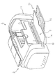
図1において、プリンタ1は後部に「被記録媒体」、「被搬送媒体」の一例としての記録用紙(以下「用紙P」と言う)を傾斜姿勢でセット可能な給送装置2を備え、装置前方には、装置手前側に開くことにより用紙Pをスタックする開状態(図2)と、当該開状態から略垂直な立設状態となる様にして閉じた収納状態(図1)と、を開閉(回動)動作によって切り換え可能に構成されたスタッカ13を、装置底部を形成する下ケース17(図4参照)に備えている。
In FIG. 1, a printer 1 is provided with a
スタッカ13は図2に示すようにスタッカ本体14とサブスタッカ15とによって構成されるとともに、スタッカ本体14の回動軸14a(図4、5参照)を中心に回動可能となっていて、プリンタ手前側に回動して開いた状態で、スタッカ本体14からサブスタッカ15を引き出すことにより、用紙Pをスタックするスタック面が形成される。
プリンタ1の装置外部はケース状のハウジング11によって覆われ、ハウジング11の中央上部には、インクカートリッジ交換等の作業を行う為の開閉自在なカバー12が設けられ、これら給送装置2、スタッカ13、ハウジング11、カバー12によって外観が構成されている。
As shown in FIG. 2, the
The outside of the printer 1 is covered with a case-shaped
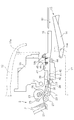
以下、図4、5を参照しながらプリンタ1の用紙搬送経路について詳説する。図4において、給送装置2は、ホッパ21と、給送ローラ23と、リタードローラ27と、ガイドローラ25および26とを備えて構成され、用紙Pをインクジェット記録ヘッド39へと搬送する「搬送手段」を構成する搬送駆動ローラ33および搬送従動ローラ34へ向けて、セットされた用紙Pを1枚ずつ給送する。
Hereinafter, the paper conveyance path of the printer 1 will be described in detail with reference to FIGS. In FIG. 4, the
より詳しくは、ホッパ21は板状体から成り、上部の揺動支点(図示せず)を中心に揺動可能に構成され、揺動することにより、ホッパ21上に支持された用紙Pを給送ローラ23に圧接させ、または、給送ローラ23から離間させる。給送ローラ23は側面視略D形の形状を成し、その円弧部分によって圧接した用紙Pを下流側へ給送する一方で、用紙Pが給送された後の、搬送駆動ローラ33および搬送従動ローラ34による用紙Pの搬送動作中においては、搬送負荷を生じさせない様に図示する様にその平坦部が用紙Pと対向する様に制御される。
More specifically, the
リタードローラ27は、給送ローラ23の円弧部分と圧接可能に設けられている。リタードローラ27は、用紙Pの重送が発生せずに、1枚だけ用紙Pが給送されている場合にはこの用紙Pに接して従動回転(図4の時計回り)し、用紙Pが給送ローラ23とリタードローラ27との間に複数枚存在する場合には、用紙間の摩擦係数が用紙Pとリタードローラ27との間の摩擦係数よりも低いため、回転せずに停止した状態となる。従ってこれにより、給送されるべき最上位の用紙Pにつられて重送されようとする次位以降の用紙Pが、給送ローラ23から下流側へ進まずに、重送が防止される。
ガイドローラ25および26は自由回転可能に設けられ、図示する様に搬送駆動ローラ33および搬送従動ローラ34によって用紙Pを搬送中に、用紙Pが給送ローラ23と接触して搬送負荷を生じさせない役割を担っている。
The
The
給送装置2によって給送される用紙Pはガイド29に案内されて、モータによって回転駆動される搬送駆動ローラ33と、該搬送駆動ローラ33に圧接して従動回転する搬送従動ローラ34に到達する。搬送従動ローラ34はホルダ31に軸支され、ホルダ31は、プリンタ1の基体を構成するメインフレーム(図示せず)に捻りコイルばね(図示せず)を介して取り付けられている。搬送駆動ローラ33に到達した用紙Pは、搬送駆動ローラ33と搬送従動ローラ34とによってニップされつつ(挟まれつつ)搬送駆動ローラ33が回転することにより、下流側のインクジェット記録ヘッド39と対向する領域へ搬送される。尚、本実施形態において搬送駆動ローラ33の直径は約10mmであり、搬送従動ローラ34の直径は約5mmである。
The paper P fed by the
搬送駆動ローラ33の下流側にはインクジェット記録ヘッド(以下「記録ヘッド」と言う)39と、これに対向してプラテン41とが配設されている。記録ヘッド39はキャリッジ35の底部に設けられ、当該キャリッジ35は主走査方向に延びるキャリッジガイド軸37にガイドされながら、図示しない駆動モータによって主走査方向に往復動する様に駆動される。また、キャリッジ35は、複数色の各色毎に独立したインクカートリッジ(図示せず)を搭載し、記録ヘッド39へとインクを供給する。
An ink jet recording head (hereinafter referred to as “recording head”) 39 and a
用紙Pと記録ヘッド39との距離を規定するプラテン41には、記録ヘッド39と対向する面にリブが形成されているとともに、凹部42、42が形成されている。凹部42は、用紙Pの端部から外れた領域に吐出するインクを打ち捨てる為のものであり、これにより、用紙Pの端部に余白無く印刷を行う所謂フチ無し印刷が実行可能となっている。尚、凹部42には、打ち捨てられたインクを吸収するインク吸収材(図示せず)が配設され、該インク吸収材から、プラテン41の下部に設けられた廃液トレイ(図示せず)へとインクが案内される。
On the
続いて、記録ヘッド39の下流側には、補助ローラ46と、「排出手段」を構成する排出駆動ローラ44及び排出従動ローラ45が設けられている。排出駆動ローラ44は回転駆動される軸体の軸方向に複数設けられ、排出従動ローラ45は主走査方向に長い金属板材によって形成されたフレーム47に設けられるとともに排出駆動ローラ44に接して従動回転する。記録ヘッド39によって記録の行われた用紙Pはこれらローラにニップされてスタッカ13へ向けて排出される。尚、これらローラの上流側に位置する補助ローラ46は用紙Pに上方から接して従動回転し、用紙Pの浮き上がりを防止して用紙Pと記録ヘッド39との距離を一定に保つ機能を果たす。
Subsequently, on the downstream side of the
以上が用紙搬送経路の概略であるが、プリンタ1は、被記録媒体としての用紙Pの他に、コンパクトディスクに代表される光ディスクのラベル面に直接インクジェット記録可能に構成されている。図3に示す様に、「被記録媒体」「薄板状体」としての光ディスクDは、プレート形状を成す「被搬送媒体」としてのトレイ50にセットされた状態で、プリンタ1における直線的な用紙搬送経路を搬送される。トレイ50はプリンタ1とは別体に構成され、プリンタ1前方側(図5の右側)から後述するトレイガイド18に支持されながら、プリンタ1の後方側(図5の左側)へ向けて差し込まれる。
The above is the outline of the paper conveyance path. The printer 1 is configured to be capable of ink jet recording directly on the label surface of an optical disk represented by a compact disk in addition to the paper P as a recording medium. As shown in FIG. 3, an optical disk D as a “recording medium” or “thin plate-like body” is set in a
より詳しくは、図2乃至図5において符号18はトレイ50を用いて光ディスクDに記録を行う際に、トレイ50をガイドするトレイガイドを示している。トレイガイド18は、排出駆動ローラ44及び排出従動ローラ45の下流側において開閉自在(回動自在)に設けられ、図3、図5に示す様に装置手前に向けて開くことによりトレイ50を支持する開状態と、当該開状態から図2、図4に示す様に略垂直な立設状態となる様に閉じた収納状態と、を回動することによって切り換え可能に設けられている。
More specifically,
このトレイガイド18と、スタッカ13とは、図4から図5への変化に示す様に各々同様な回動動作を行うことによって開状態と収納状態とを切り換える(開閉する)。即ち、収納状態では各々略垂直な立設状態となり、当該垂直姿勢から装置前方側に倒れる様に回動して開くことで、使用状態となる。そして、各々が収納状態にあるときには、トレイガイド18がスタッカ13の内側に略平行に位置する様になり、各々が開状態にあるときには、トレイガイド18がほぼ水平な姿勢でスタッカ13の上に位置し、スタッカ13が、排出された用紙Pが落下しない様に緩やかに上を向いた姿勢で保持される。
As shown in the change from FIG. 4 to FIG. 5, the
以上がプリンタ1の概略構成であり、以下、図6乃至図10を参照しながら、トレイ50について詳説する。ここで、図6はトレイ50の平面図、図7はトレイ50先端の外観斜視図、図8(A)は突出部57の平面図、同図(B)は突出部57の側面図、図9はトレイ50の先端が搬送駆動ローラ33と搬送従動ローラ34との間に入り込む様子を示す動作説明図、図10は搬送従動ローラ34と突出部57との位置関係を示す平面図である。
The above is the schematic configuration of the printer 1, and the
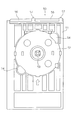
図6に示すように、トレイ50は平面視において長方形の形状を成し、搬送駆動ローラ33と搬送従動ローラ34(図5)とによってニップ可能なプレート形状を成すとともに、搬送駆動ローラ33の回転にともなって副走査送りされる。
トレイ50は、トレイ本体51とセット部52とを備えるように樹脂材料によって一体的に形成されている。セット部52は、図示するように平面視において円形の形状を成す凹部によって構成されている。セット部52の中心には凸部53が形成され、光ディスクDがセット部52にセットされた際に、光ディスクDの中心穴(図示せず)が凸部53に嵌合し、これによって光ディスクDのセット部52における位置が定まるようになっている。尚、セット部52の周囲に形成された穴54、54は、光ディスクDの取り出し(イジェクト)用穴である。
As shown in FIG. 6, the
The
図6の上下方向はトレイ50の搬送方向となっていて、トレイ50を図3に示したようにトレイガイド18を介してプリンタ1に差し込む(給送する)際には、図6の上方を先端として差し込むようになっている。即ち、符号56は、トレイ50の先端を示している。そして、トレイ50の先端には、図7にも示すように「突起部」としての舌片部57、57が、トレイ50の搬送方向(差し込み方向)に突出するように、トレイ50と一体的に形成されている。
6 is the transport direction of the
この舌片部57は、図示するようにトレイ50の搬送方向と直交する方向(図6の左右方向、即ち幅方向)に所定の間隔を空けて複数(本実施形態では、2つ)配置され、平面視においては、図8(A)に詳しく示すように先端に向かって先細りするように形成されている。本実施形態では、幅aは約9mm、先端56からの突出量bは約3mmに設定されている。尚、本実施形態では図示するように先端に向かって緩やかな弧を描くように形成されているが、これに限られず、先端に向かって先細りするような形状であればどのようなものでも構わない。或いは、先端に向かって先細りするような形状でなくても構わない。
A plurality (two in this embodiment) of the
次に、この舌片部57は、トレイ50の縦断面(トレイ50を搬送方向に沿って切断した際の断面)視において、図8(B)に示すような形状を成している。即ち、先端に向かって先細りするとともに、その底面57bは、トレイ本体51の底面51aとともに平坦な面を形成するように成されている。
また、トレイ50の先端56は、舌片部57と同様に先端に向かって先細りするとともに、その上面56aが、舌片部57の上面57aから上方に突出しないよう形成されている。
Next, the
Further, the
尚、本実施形態では、舌片部57先端の厚さ寸法cが約0.5mm、舌片部57の上面57aの傾斜角(トレイ本体51の底面51bに対する傾斜角)が約8°、先端56の上面56aの傾斜角(トレイ本体51の底面51bに対する傾斜角)が約12°となっている。
In this embodiment, the thickness c of the tip of the
以下、舌片部57の作用効果について主として図9を参照しつつ説明する。図3を参照しつつ説明したように、トレイ50をプリンタ1に差し込む(用紙搬送経路に給送する)際には、トレイ50の先端56を頭にして、トレイガイド18を介してプリンタ1後方側へ向けて差し込む。このとき、排出従動ローラ45は、トレイガイド18が開状態(使用状態)となるに従って図5に示すように排出駆動ローラ44から離間した状態となっていて、これによってトレイ50にセットされた光ディスクDが排出従動ローラ45に接することがなく、即ち光ディスクDへダメージを与えることなくトレイ50をプリンタ1に差し込む(セットする)ことができる。本実施形態においては、トレイ50がユーザによってプリンタ1に差し込まれる(セットされる)と、トレイ50の先端はプラテン41上に到達し(搬送駆動ローラ33及び搬送従動ローラ34には到達していない)、以降は、図示しない搬送手段によって、トレイ50は搬送駆動ローラ33及び搬送従動ローラ34に向けて自動的に送られるように構成されている。
Hereinafter, the effect of the
ここで、搬送駆動ローラ33の回転によってトレイ50を副走査送りする為には、トレイ50の先端56を、搬送駆動ローラ33と、当該搬送駆動ローラ33に圧接している搬送従動ローラ34との間に入り込ませる必要があるが、トレイ50の先端56には、トレイ50の搬送方向に突出するような形状を成す舌片部57が、トレイ50と一体的に形成されている。従ってトレイ50を搬送駆動ローラ33及び搬送従動ローラ34に向けて送ると、最初に舌片部57が搬送駆動ローラ33と搬送従動ローラ34との間に入り込み(図9(B))、これがきっかけとなってその後にトレイ50の先端56が搬送駆動ローラ33と搬送従動ローラ34との間に入り込み、やがてトレイ50は両ローラによってニップされた状態となる(図9(C))。
Here, in order to perform sub-scan feed of the
即ち、舌片部57によってトレイ50先端の面積(平面視による)が極めて小さくなるので、小さい力でトレイ50の先端56を搬送駆動ローラ33と搬送従動ローラ34との間に容易に入り込ませる(換言すれば、両ローラの間を小さい力で容易にこじ開ける)ことができる。従ってこれにより、搬送従動ローラ34を搬送駆動ローラ33から離間(レリース)させる手段を用いることなく、トレイ50を搬送駆動ローラ33と搬送従動ローラ34との間に確実に入り込ませることができ、プリンタ1のコストアップを防止することができる。
That is, since the area of the front end of the tray 50 (as viewed in plan) is extremely reduced by the
そして、舌片部57はトレイ50(トレイ本体51)と一体的に形成されているので、トレイ50のコストアップを防止することができるとともに、強度が向上し、トレイ50を給送する際に破損等が生じにくい。加えて、トレイ50(トレイ本体51)の底面51bを段差なく滑らかに形成することができるので、トレイ50の副走査送りを常に精度良く行うことができる。
And since the
尚、舌片部57は、搬送駆動ローラ33及び搬送従動ローラ34によってトレイ50が挟持された際に、トレイ50において生じる応力が集中する応力集中部(本実施形態においては前記応力が最も大なる部分)ということもできる。即ち、この様な応力集中部によってトレイ50先端の面積(平面視による)が極めて小さくなるので、小さい力でトレイ50の先端を搬送駆動ローラ33と搬送従動ローラ34との間に容易に入り込ませることができる。
The
また、舌片部57は、トレイ50の縦断面視において先端に向かって先細りするような形状を成しているので、トレイ50をより一層容易に搬送駆動ローラ33と搬送従動ローラ34との間に入り込ませることができる。加えて、トレイ50の先端56が、トレイ50の縦断面視において先端に向かって先細りするとともに、その上面56aが、舌片部57の上面57aから上方に突出しないよう形成されているので、トレイ50の先端56が搬送駆動ローラ33と搬送従動ローラ34との間に入り込む際に、引っ掛かりなく円滑に入り込むことができる。
Further, since the
即ち、図10に示すように搬送従動ローラ34がトレイ50の幅方向に複数設けられた構成において、トレイ50を搬送駆動ローラ33及び搬送従動ローラ34に向けて給送すると、搬送駆動ローラ33と搬送従動ローラ34との間を舌片部57が通過する際に、当該舌片部57に圧接する搬送従動ローラ(図10において符号34B、34Dで示す)と、舌片部57に圧接しないフリーな状態の搬送従動ローラ(図10において符号34A、34Cで示す)とが混在する。
That is, as shown in FIG. 10, in a configuration in which a plurality of transport driven
ここで、当該フリーな状態の搬送従動ローラ34A、34Cは、舌片部57に圧接する搬送従動ローラ34B、34Dに比べて、搬送駆動ローラ33からの離間幅が小さくなる(図9(B)参照)。従ってこの状態から、やがてトレイ50の先端56が搬送駆動ローラ33と搬送従動ローラ34との間を通過する際には、トレイ50の先端56が搬送従動ローラ33に引っ掛かる虞がある。しかし、トレイ50の先端56は上述の通り先細り形状となっているので、トレイ50の先端56を引っ掛かりなく円滑に搬送駆動ローラ33と搬送従動ローラ34との間を通過させることができる。また、先端56の上面56aが、舌片部57の上面57aから突出していないので、舌片部57による搬送駆動ローラ33と搬送従動ローラ34との間の上記こじ開け効果を阻害することがない。
Here, the transport driven
尚、舌片部57は、上述したように平面視においても先端に向かって先細りするような形状を成しているので、トレイ50をより一層容易に搬送駆動ローラ33と搬送従動ローラ34との間に入り込ませることができる。加えて、舌片部57は、トレイ50の幅方向に所定の間隔を空けて複数設けられているので、トレイ50の先端56が搬送駆動ローラ33と搬送従動ローラ34との間に入り込む際の、トレイ50の斜行(スキュー)を防止或いは軽減することができる。
Note that the
加えて、舌片部57は、図10に示すように搬送従動ローラ34を軸支するホルダ31との関係において、搬送従動ローラ34が搬送駆動ローラ33に圧接するようホルダ31を付勢する捻りコイルばね36がホルダ31に付勢力を作用させる位置(本実施形態では、ホルダ31の幅方向(トレイ50の搬送方向と直交する方向)のほぼ中心)から最も離れた位置で搬送従動ローラ34と圧接するよう配置されている。つまり、搬送従動ローラ34から受ける圧接力が最も弱くなる位置で搬送従動ローラ34と圧接するよう配置されているので、トレイ50を、より一層軽い力で搬送駆動ローラ33と搬送従動ローラ34との間に入り込ませることができる。
In addition, the
また、本実施形態においては、図10に示すようにホルダ31及び搬送従動ローラ34との関係において、2つの舌片部57がほぼ同じ位置、つまり搬送従動ローラ34から受ける圧接力が等しくなる位置に配置されている。具体的には、本実施形態においては図10に示すようにホルダ31の右側(図10の右側)に軸支された搬送従動ローラ34(34B、34D)の、幅方向中心から右側に偏倚した位置に対応する場所に配置されている。
Further, in the present embodiment, as shown in FIG. 10, in the relationship between the
即ち、ホルダ31は、その幅方向(トレイ50の搬送方向と直交する方向)のほぼ中心位置に捻りコイルばね36の付勢力が作用し、これにより搬送従動ローラ34が搬送駆動ローラ33に圧接する方向に付勢されている。従って2つの舌片部57が、搬送従動ローラ34と圧接する位置が異なると、搬送従動ローラ34が舌片部57を押圧する力が異なることとなる為、これによってトレイ50を搬送駆動ローラ33と搬送従動ローラ34との間に差し込んだ際に力の不均衡によって斜行が生じる虞がある。
That is, the urging force of the
しかし、上述のように2つの舌片部57は、トレイ50の幅方向に複数配置されたホルダ31及び搬送従動ローラ34との関係においてほぼ同じ位置(本実施形態では搬送従動ローラ34との圧接力が最も弱くなる位置)に配置されているので、搬送従動ローラ34が舌片部57を押圧する際の押圧力にばらつきが生じなく、トレイ50の斜行を防止することが可能となっている。
However, as described above, the two
尚、本実施形態においては、被搬送媒体の一例として光ディスクDをセット可能なトレイ50をとりあげて説明したが、トレイ50に限られず、例えばボード紙等の厚紙であっても、同様な突出部を一体的に設けることで、搬送従動ローラ34のレリース手段を用いることなく、且つ給送時の破損等を招くことなく、容易に搬送駆動ローラ33と搬送従動ローラ34との間に入り込ませることが可能となる。
In the present embodiment, the
1 インクジェットプリンタ、2 給送装置、3 用紙排出口、11 ハウジング、12 上カバー、13 スタッカ、14 スタッカ本体、15 サブスタッカ、18 トレイガイド、21 ホッパ、23 給送ローラ、25,26 ガイドローラ、27 リタードーラ、29 ガイド、31 ホルダ、32 揺動軸、33 搬送駆動ローラ、34 搬送従動ローラ、35 キャリッジ、37 キャリッジガイド軸、39 インクジェット記録ヘッド、41 プラテン、42 凹部、43 リブ、44 排出駆動ローラ、45 排出従動ローラ、46 補助ローラ、47 フレーム、50 トレイ、51 トレイ本体、52 セット部、53 凸部、54 イジェクト穴、56 先端、57 舌片部、D 光ディスク、P 記録用紙。 DESCRIPTION OF SYMBOLS 1 Inkjet printer, 2 Feeding device, 3 Paper discharge port, 11 Housing, 12 Upper cover, 13 Stacker, 14 Stacker main body, 15 Sub stacker, 18 Tray guide, 21 Hopper, 23 Feed roller, 25, 26 Guide roller, 27 Retarder, 29 guide, 31 holder, 32 swing shaft, 33 transport drive roller, 34 transport driven roller, 35 carriage, 37 carriage guide shaft, 39 inkjet recording head, 41 platen, 42 recess, 43 rib, 44 discharge drive roller, 45 discharge driven roller, 46 auxiliary roller, 47 frame, 50 tray, 51 tray body, 52 set part, 53 convex part, 54 eject hole, 56 tip, 57 tongue piece part, D optical disk, P recording paper.
Claims (5)
前記被搬送媒体の先端部から搬送方向に突出する突出部を備え、 A projecting portion projecting in the transport direction from the tip of the transported medium;
前記突出部の上面が、前記先端部の上面よりも高くなるように形成されていることと、 The upper surface of the protrusion is formed to be higher than the upper surface of the tip;
前記突出部の搬送方向に直交する方向の幅が、前記先端部の搬送方向に直交する方向の幅よりも狭いことと、 The width in the direction perpendicular to the conveying direction of the protrusion is narrower than the width in the direction perpendicular to the conveying direction of the tip,
前記搬送の際に、前記先端部と前記突出部とが前記付勢手段により付勢力を受けることと、を特徴とする被搬送媒体。 A medium to be transported, wherein the leading end portion and the protruding portion receive a biasing force by the biasing means during the transport.
請求項1乃至4のいずれか1項に記載の被搬送媒体と、前記第1のローラと前記第2のローラと前記付勢手段と前記ホルダ部材を有し当該被搬送媒体を搬送可能である前記記録装置と、を備える記録装置システムであって、 5. The transported medium according to claim 1, the first roller, the second roller, the urging unit, and the holder member, and the transported medium can be transported. A recording apparatus system comprising the recording apparatus,
前記記録装置は、前記第2のローラを介して前記付勢力を前記第1のローラに伝えることと、 The recording apparatus transmits the biasing force to the first roller via the second roller;
前記搬送の際に、前記突出部が前記付勢力を受けた後に前記先端部が前記付勢力を受けることと、を特徴とする記録装置システム。 The recording apparatus system according to claim 1, wherein the tip portion receives the urging force after the projecting portion receives the urging force during the conveyance.
Priority Applications (1)
| Application Number | Priority Date | Filing Date | Title |
|---|---|---|---|
| JP2009236030A JP4770974B2 (en) | 2009-10-13 | 2009-10-13 | Conveyed medium and recording apparatus system |
Applications Claiming Priority (1)
| Application Number | Priority Date | Filing Date | Title |
|---|---|---|---|
| JP2009236030A JP4770974B2 (en) | 2009-10-13 | 2009-10-13 | Conveyed medium and recording apparatus system |
Related Parent Applications (1)
| Application Number | Title | Priority Date | Filing Date |
|---|---|---|---|
| JP2004323430A Division JP4419804B2 (en) | 2004-11-08 | 2004-11-08 | Media to be transported |
Related Child Applications (2)
| Application Number | Title | Priority Date | Filing Date |
|---|---|---|---|
| JP2010101932A Division JP5041028B2 (en) | 2010-04-27 | 2010-04-27 | Media to be transported |
| JP2010101931A Division JP4873090B2 (en) | 2010-04-27 | 2010-04-27 | Media to be transported |
Publications (3)
| Publication Number | Publication Date |
|---|---|
| JP2010006080A JP2010006080A (en) | 2010-01-14 |
| JP2010006080A5 JP2010006080A5 (en) | 2010-06-03 |
| JP4770974B2 true JP4770974B2 (en) | 2011-09-14 |
Family
ID=41587076
Family Applications (1)
| Application Number | Title | Priority Date | Filing Date |
|---|---|---|---|
| JP2009236030A Expired - Fee Related JP4770974B2 (en) | 2009-10-13 | 2009-10-13 | Conveyed medium and recording apparatus system |
Country Status (1)
| Country | Link |
|---|---|
| JP (1) | JP4770974B2 (en) |
Family Cites Families (5)
| Publication number | Priority date | Publication date | Assignee | Title |
|---|---|---|---|---|
| JPH0267329A (en) * | 1988-09-02 | 1990-03-07 | Nippon Soda Co Ltd | Obtaining polymer film |
| JP3390391B2 (en) * | 1999-12-16 | 2003-03-24 | エヌイーシーアクセステクニカ株式会社 | Recording paper feed support |
| JP3514387B2 (en) * | 2001-05-31 | 2004-03-31 | セイコーエプソン株式会社 | Recording device and tray for transporting recording material |
| JP3768929B2 (en) * | 2002-07-10 | 2006-04-19 | キヤノン株式会社 | Recording device |
| JP2004247007A (en) * | 2003-02-17 | 2004-09-02 | Canon Inc | Recorder |
-
2009
- 2009-10-13 JP JP2009236030A patent/JP4770974B2/en not_active Expired - Fee Related
Also Published As
| Publication number | Publication date |
|---|---|
| JP2010006080A (en) | 2010-01-14 |
Similar Documents
| Publication | Publication Date | Title |
|---|---|---|
| US8432422B2 (en) | Transferred medium | |
| US7591552B2 (en) | Liquid ejecting apparatus | |
| JP4930041B2 (en) | Paper feed mechanism and recording apparatus having the same | |
| JP4356615B2 (en) | Recording apparatus and liquid ejecting apparatus | |
| JP3770317B2 (en) | Recording medium conveying tray, positioning adapter, ink jet recording apparatus | |
| JP4450209B2 (en) | Recording apparatus and liquid ejecting apparatus | |
| JP3835535B2 (en) | Recording device | |
| JP4770974B2 (en) | Conveyed medium and recording apparatus system | |
| JP5041028B2 (en) | Media to be transported | |
| JP4873090B2 (en) | Media to be transported | |
| JP2007050989A (en) | Recording medium stacker, recording device, and liquid jet device | |
| JP4497325B2 (en) | Recording medium transport tray | |
| JP4487780B2 (en) | Recording system, tray | |
| JP5375998B2 (en) | Recording device | |
| JP5360694B2 (en) | Recording device | |
| JP4057300B2 (en) | Recording medium transport tray | |
| JP2009029558A (en) | Medium to be conveyed and recording device | |
| JP4826856B2 (en) | Recording medium transport tray | |
| JP4883168B2 (en) | Disc tray and recording device | |
| JP4788818B2 (en) | Recording apparatus and liquid ejecting apparatus | |
| JP4788817B2 (en) | Recording apparatus and liquid ejecting apparatus | |
| JP5316632B2 (en) | Paper feed mechanism and recording apparatus having the same | |
| JP2004155585A (en) | Paper feeder and recording device equipped therewith | |
| JP2006273486A (en) | Recorded medium detecting device, recording device and liquid injecting device | |
| JP2005144932A (en) | Recording apparatus and liquid jet apparatus |
Legal Events
| Date | Code | Title | Description |
|---|---|---|---|
| A621 | Written request for application examination |
Free format text: JAPANESE INTERMEDIATE CODE: A621 Effective date: 20091013 |
|
| A521 | Written amendment |
Free format text: JAPANESE INTERMEDIATE CODE: A523 Effective date: 20100420 |
|
| A977 | Report on retrieval |
Free format text: JAPANESE INTERMEDIATE CODE: A971007 Effective date: 20110518 |
|
| TRDD | Decision of grant or rejection written | ||
| A01 | Written decision to grant a patent or to grant a registration (utility model) |
Free format text: JAPANESE INTERMEDIATE CODE: A01 Effective date: 20110524 |
|
| A61 | First payment of annual fees (during grant procedure) |
Free format text: JAPANESE INTERMEDIATE CODE: A61 Effective date: 20110606 |
|
| FPAY | Renewal fee payment (event date is renewal date of database) |
Free format text: PAYMENT UNTIL: 20140701 Year of fee payment: 3 |
|
| R150 | Certificate of patent or registration of utility model |
Ref document number: 4770974 Country of ref document: JP Free format text: JAPANESE INTERMEDIATE CODE: R150 Free format text: JAPANESE INTERMEDIATE CODE: R150 |
|
| S531 | Written request for registration of change of domicile |
Free format text: JAPANESE INTERMEDIATE CODE: R313531 |
|
| R350 | Written notification of registration of transfer |
Free format text: JAPANESE INTERMEDIATE CODE: R350 |
|
| LAPS | Cancellation because of no payment of annual fees |