JP4765121B2 - Shield machine - Google Patents
Shield machine Download PDFInfo
- Publication number
- JP4765121B2 JP4765121B2 JP2007085415A JP2007085415A JP4765121B2 JP 4765121 B2 JP4765121 B2 JP 4765121B2 JP 2007085415 A JP2007085415 A JP 2007085415A JP 2007085415 A JP2007085415 A JP 2007085415A JP 4765121 B2 JP4765121 B2 JP 4765121B2
- Authority
- JP
- Japan
- Prior art keywords
- shield
- jack
- section
- area
- horseshoe
- Prior art date
- Legal status (The legal status is an assumption and is not a legal conclusion. Google has not performed a legal analysis and makes no representation as to the accuracy of the status listed.)
- Expired - Fee Related
Links
- 238000009412 basement excavation Methods 0.000 claims description 40
- 238000005553 drilling Methods 0.000 claims description 14
- 230000001788 irregular Effects 0.000 claims description 9
- 230000002093 peripheral effect Effects 0.000 claims description 8
- 235000015277 pork Nutrition 0.000 description 8
- 238000005192 partition Methods 0.000 description 7
- 230000008602 contraction Effects 0.000 description 4
- 230000007935 neutral effect Effects 0.000 description 4
- 239000004576 sand Substances 0.000 description 4
- 239000002689 soil Substances 0.000 description 2
- 238000005452 bending Methods 0.000 description 1
- 230000007423 decrease Effects 0.000 description 1
- 230000005484 gravity Effects 0.000 description 1
- 230000000149 penetrating effect Effects 0.000 description 1
- 125000006850 spacer group Chemical group 0.000 description 1
- 239000002699 waste material Substances 0.000 description 1
- XLYOFNOQVPJJNP-UHFFFAOYSA-N water Substances O XLYOFNOQVPJJNP-UHFFFAOYSA-N 0.000 description 1
Images


Landscapes
- Excavating Of Shafts Or Tunnels (AREA)
Description
本発明は、切羽に対する掘削断面が上下で非対称の異形掘削断面となっているシールド掘進機に関する。 The present invention relates to a shield machine excavation cross section for the working face has become irregular drilling section asymmetrical above under.
シールド掘進機は、筒状のシールドフレームを有する掘進機本体と、掘進機本体の前部に切羽を切削するために配設されたカッタと、カッタで切削された土砂を掘進機本体の内部に取り込むための排土装置と、セグメントをシールドフレームの内周面に沿ってリング状に組み立てるために掘進機本体の内部に設けられたエレクタと、リング状に組み立てられたセグメントに反力を取って掘進機本体を前進させるためにシールドフレームの内周面にその周方向に間隔を隔てて複数設けられたシールドジャッキとを備えている。 The shield machine has a main body having a cylindrical shield frame, a cutter disposed to cut the face at the front of the machine, and earth and sand cut by the cutter inside the machine. Take the reaction force to the earth removing device for taking in, the erector provided inside the excavator body to assemble the segment in a ring shape along the inner peripheral surface of the shield frame, and the segment assembled in the ring shape In order to advance the main body of the excavator, a plurality of shield jacks are provided on the inner peripheral surface of the shield frame at intervals in the circumferential direction.
かかるシールド掘進機は、シールドジャッキを伸長させてカッタを切羽に押し付け、カッタを掘進方向と平行な軸廻りに回転させる等してそのカッタで切羽を切削し、掘削された土砂を排土装置(スクリューコンベヤ等)によって掘進機本体の内部に取り込み、掘進機本体をシールドジャッキの伸長ストロークに応じて前進(掘進)させ、爾後、シールドジャッキを収縮させて既設のセグメントとシールドジャッキとの間にスペースを形成し、そのスペースにエレクタによってセグメントをリング状に組み立て、トンネルを構築するものである。 Such shield machine extends the shield jack, presses the cutter against the face, rotates the cutter around an axis parallel to the direction of excavation, etc., cuts the face with the cutter, and removes the excavated earth and sand ( It is taken into the inside of the excavator main body by a screw conveyor, etc., and the excavator main body is advanced (excavated) according to the extension stroke of the shield jack. Is formed, and the segments are assembled in a ring shape by an erector in the space to construct a tunnel.
従来のシールド掘進機は、一般に、切羽に対する掘削断面が上下及び/又は左右で対称となっており、そのため、各シールドジャッキは、同じジャッキ推力のものを、シールドフレームの周方向に等間隔を隔てて配置されていた。すなわち、切羽に対する掘削断面が上下及び/又は左右で対称であれば、同じジャッキ推力のシールドジャッキをシールドフレームの周方向に等間隔を隔てて配置しても、切羽に対するカッタの押圧力が掘削断面の上下及び/又は左右でアンバランスとなることはない。 The conventional shield machine generally has a digging cross section with respect to the face that is symmetrical in the vertical and / or left and right directions. Therefore, each shield jack has the same jack thrust at equal intervals in the circumferential direction of the shield frame. Had been placed. In other words, if the excavation cross section with respect to the face is symmetrical vertically and / or left and right, even if shield jacks having the same jack thrust are arranged at equal intervals in the circumferential direction of the shield frame, the pressing force of the cutter against the face will be There is no imbalance between the top and bottom and / or left and right.
しかし乍ら、近年、掘削断面が上下及び/又は左右で非対称の異形掘削断面であるシールド掘進機が開発されている。例えば、複数車線が並設される道路トンネル等の分野においては、掘削断面形状が馬蹄形(おむすび形)である上下非対称のシールド掘進機の開発が要望されている。馬蹄形トンネルは、その最も幅広の部分に複数の車線が並設されるところ、その最も幅広の部分を直径とした断面円形のトンネルと対比すると、無駄掘り領域が低減される。 However, in recent years, shield machines have been developed in which the excavation cross-section is an atypical excavation cross-section that is asymmetric in the vertical and / or left-right direction. For example, in the field of road tunnels in which a plurality of lanes are arranged side by side, there is a demand for the development of an asymmetric shield shield machine having an excavating cross-sectional shape that is a horseshoe shape. In the horseshoe-shaped tunnel, a plurality of lanes are juxtaposed at the widest portion thereof. However, when compared with a tunnel having a circular cross section having the widest portion as a diameter, a waste digging region is reduced.
このような掘削断面形状が馬蹄形であるシールド掘進機においては、掘削断面(馬蹄形)の図心(重心)より下方の部分(図心を通って左右方向に延びる仮想ラインよりも下方の部分)は、図心より上方の部分(仮想ラインよりも上方の部分)よりも面積が大きい。このため、同じジャッキ推力のシールドジャッキを掘進機本体の内部に馬蹄形の掘削断面の周縁に沿って等間隔を隔てて配設すると、切羽に対する掘削断面において、図心より下方の部分の推力が不足してしまう。 In such a shield machine with a horseshoe-shaped excavation cross-section, the portion below the centroid (center of gravity) of the excavation cross-section (horse-shoe shape) (the portion below the virtual line extending in the left-right direction through the centroid) is The area is larger than the part above the centroid (the part above the virtual line). For this reason, if shield jacks with the same jack thrust are arranged at equal intervals along the periphery of the horseshoe-shaped excavation cross section inside the main body of the excavator, the thrust below the centroid is insufficient in the excavation cross section with respect to the face Resulting in.
この対策として、図心より下方の部分におけるシールドジャッキの配設間隔を、図心より上方の部分におけるシールドジャッキの配設間隔よりも狭めてジャッキの配設密度を高めれば、上述の推力不足の問題は解消するが、シールドジャッキの配設間隔を狭めると、隣接するシールドジャッキのシュー(既設のセグメントに当接する部分)同士が干渉してしまうため、実際に成立させることは困難である。 As a countermeasure against this, if the arrangement interval of the shield jacks in the portion below the centroid is narrower than the arrangement interval of the shield jacks in the portion above the centroid to increase the arrangement density of the jacks, the above-mentioned thrust is insufficient. Although the problem is solved, if the interval between the shield jacks is reduced, the shoes of the adjacent shield jacks (portions that abut against the existing segments) interfere with each other, and it is difficult to actually establish it.
なお、特許文献1には、床部が一体的に形成された肉厚のインバートセグメントと通常のアーチセグメントとを用いて床部付きの断面円形トンネルを構築するシールド掘進機が記載されている。このシールド掘進機は、インバートセグメントを押圧するインバートセグメント用シールドジャッキの推進力の作用点が、アーチセグメントを押圧するアーチセグメント用シールドジャッキの推進力の作用点よりもシールドフレームの中心寄りとされ、インバートセグメント用シールドジャッキの推力が、アーチセグメント用シールドジャッキの推力よりも大きく設定されている。
特許文献1に記載されたシールド掘進機においては、推力が大きいインバートセグメント用シールドジャッキが掘進機本体に作用するモーメントの腕の長さが短く、推力が小さいアーチセグメント用シールドジャッキが掘進機本体に作用するモーメントの腕の長さが長いため、推力が大きいインバートセグメント用シールドジャッキがセグメントを押圧することによって掘進機本体に生じるモーメントと、推力が小さいアーチセグメント用シールドジャッキがセグメントを押圧することによって掘進機本体に生じるモーメントとのバランスをとることができる。
In the shield machine described in
しかし乍ら、特許文献1には、掘削断面が円形のシールド掘進機が記載されているに過ぎず、本願発明の前提となる、切羽に対する掘削断面が上下で非対称の異形掘削断面であるシールド掘進機は、開示も示唆もされていない。また、異形掘削断面のシールド掘進機について記載されていない以上、異形掘削断面が、下部が上部に比べて左右方向に膨出した馬蹄形掘削断面であり、馬蹄形掘削断面が、該馬蹄形掘削断面の図心を通って掘進機本体を横切るように左右方向に延出された仮想ラインで、馬蹄形掘削断面における仮想ラインより下方の部分である広面積部と馬蹄形掘削断面における仮想ラインより上方の部分である狭面積部とに仮想的に上下に二分割され、広面積部に配置された広面積部シールドジャッキが、狭面積部に配置された狭面積部シールドジャッキよりも、ジャッキ推力が大きいものを含み、広面積部シールドジャッキの全ジャッキのジャッキ推力を広面積部の面積で除した下側広面積部押圧力値が、狭面積部シールドジャッキの全ジャッキのジャッキ推力を狭面積部の面積で除した上側狭面積部押圧力値よりも大きいという、本願発明の技術思想も、当然、開示も示唆もされていない。
However乍Ra,
以上の事情を考慮して創案された本発明の目的は、切羽に対する掘削断面が上下で非対称の異形掘削断面のシールド掘進機において、シールドジャッキの配設間隔をその異形掘削断面の周縁に沿って等間隔としても、切羽における上記異形掘削断面の一部分に生じる推力不足の問題を回避できるシールド掘進機を提供することにある。 Purpose of the present invention described above that the situation has been made in consideration, in the shield machine of irregular drilling section of the asymmetric on under excavation cross section for the working face, along the arrangement distances of the shield jacks on the periphery of the profiled drilling section Therefore, it is an object of the present invention to provide a shield machine capable of avoiding the problem of insufficient thrust generated in a part of the deformed excavation cross section at the face even at equal intervals.
上記目的を達成するために本発明は、切羽に対する掘削断面が上下で非対称の異形掘削断面であるシールド掘進機であって、上記異形掘削断面が、下部が上部に比べて左右方向に膨出した馬蹄形掘削断面であり、掘進機本体に、既設のセグメントに反力を取って上記掘進機本体を前進させるためのシールドジャッキが、上記馬蹄形掘削断面の周縁に沿って等間隔を隔てて複数配設され、上記馬蹄形掘削断面が、該馬蹄形掘削断面の図心を通って上記掘進機本体を横切るように左右方向に延出された仮想ラインで、上記馬蹄形掘削断面における上記仮想ラインより下方の部分である広面積部と上記馬蹄形掘削断面における上記仮想ラインより上方の部分である狭面積部とに仮想的に上下に二分割され、上記シールドジャッキの内の上記広面積部に配置された広面積部シールドジャッキが、上記シールドジャッキの内の上記狭面積部に配置された狭面積部シールドジャッキよりも、ジャッキ推力が大きいものを含み、上記広面積部シールドジャッキの全ジャッキのジャッキ推力を上記広面積部の面積で除した下側広面積部押圧力値が、上記狭面積部シールドジャッキの全ジャッキのジャッキ推力を上記狭面積部の面積で除した上側狭面積部押圧力値よりも大きいものである。 To accomplish the above object, there is provided a shield machine excavation cross section is irregular excavation cross section of an asymmetric above under for the working face, the irregular drilling section is bulging in the lateral direction bottom than at the top A plurality of shield jacks are provided at equal intervals along the periphery of the horseshoe excavation section. is arranged, the horseshoe-shaped excavation cross section through the centroid of the horseshoe-shaped excavation cross section on a virtual line extending in the lateral direction so as to cross the shield machine main body, from the imaginary line in the horseshoe-shaped drilling section virtually vertically divided into two parts in a narrow area portion is an upper portion than the imaginary line in the wide area portion and the horseshoe-shaped excavation cross-section is a portion below said large-area portion of said shield jacks Arranged large area shield jack, than the narrow area portion shield jacks arranged in the narrow area portion of said shield jacks, see contains what jack thrust is large, the total jack of the wide area shield jacks The lower wide area portion pressing force value obtained by dividing the jack thrust force by the area of the wide area portion is equal to the upper narrow area portion pushing force value obtained by dividing the jack thrust force of all jacks of the narrow area portion shield jack by the area of the narrow area portion. It is larger than the pressure value .
上記下側広面積部押圧力値と上記上側狭面積部押圧力値との差が、上記狭面積部とそれより下方の上記広面積部とが夫々切羽から受ける土荷重の差に基づいて定められることが好ましい。 The difference between the pressing force value of the lower wide area portion and the pressing force value of the upper narrow area portion is determined based on the difference in earth load that the narrow area portion and the lower wide area portion below receive from the face. It is preferred that
本発明によれば、切羽に対する掘削断面が上下で非対称の異形掘削断面のシールド掘進機において、シールドジャッキの配設間隔をその異形掘削断面の周縁に沿って等間隔としても、切羽における上記異形掘削断面の一部分に生じる推力不足の問題を回避できる。 According to the present invention, the shield machine asymmetric profiled drilling section above under excavation cross section for the working face, even at equal intervals along the arrangement distances of the shield jacks on the periphery of the profiled drilling section, the profiled at working face The problem of insufficient thrust generated in a part of the excavation cross section can be avoided.
本発明の好適な実施形態を添付図面に基づいて説明する。 A preferred embodiment of the present invention will be described with reference to the accompanying drawings.
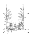
図1に示すように、本実施形態に係る推進装置を備えたシールド掘進機1は、筒状のシールドフレーム2を有する掘進機本体3と、掘進機本体3の前部に切羽を切削するために配設されたカッタ4と、カッタ4で切削された土砂を掘進機本体3の内部に取り込むための排土装置5と、掘進機本体3の内部に設けられセグメント6をシールドフレーム2の内周面に沿ってリング状に組み立てるエレクタ(図示せず)と、シールドフレーム2の内周面にその周方向に間隔を隔てて複数設けられ、リング状に組み立てられたセグメント6に反力を取って掘進機本体3を前進させるためのシールドジャッキ7とを備えている。
As shown in FIG. 1, a
シールドフレーム2には、その内部を掘進方向の前後に仕切る隔壁8が設けられており、隔壁8には、カッタ4が、掘進方向に沿った軸(回転軸)と平行な軸廻りに回転自在に支持されている。詳しくは、カッタ4の反切羽側の面には、軸方向後方に延出された中間ビーム9が周方向に間隔を隔てて複数設けられており、それら中間ビーム9の端部が、隔壁8に上記回転軸の軸廻りに回転可能に支持された回転リング10に装着されている。すなわち、カッタ4は、中間ビーム9及び回転リング10を介して、隔壁8に回転自在に支持されている。よって、回転リング10をモータ11及びギヤ12を介して回転することで、カッタ4が上記回転軸廻りに回転駆動される。カッタ4で切削された土砂は、一旦、隔壁8の前方のカッタ室13に取り込まれた後、隔壁8を貫通する排土装置5(スクリューコンベヤ)によって隔壁8の後方の坑内に搬送される。
The
シールドフレーム2は、筒状の前胴2fと後胴2rとからなり、前胴2fと後胴2rとが球面継手14を介して全方向に屈曲可能に接続され、前胴2fと後胴2rとが中折れジャッキ15を介して連結されている。前胴2fと後胴2rとを屈曲させることで、急カーブ掘進が可能となる。中折れジャッキ15は、シールドフレーム2の周方向に間隔(等間隔)を隔てて複数配設されており、図1において上方の中折れジャッキ15aと下方の中折れジャッキ15bとでサイズが異なっているが、これについては後述する。
The
後胴2rには、この後胴2rの内周面に沿ってセグメント6をリング状に組み立てるためのエレクタ(図示せず)が設けられていると共に、リング状に組み立てられたセグメント6に反力を取って掘進機本体3を前進させるためのシールドジャッキ7が設けられている。シールドジャッキ7は、シールドフレーム2の周方向に等間隔を隔てて複数配設されており、図1において上方のシールドジャッキ7aと下方のシールドジャッキ7bとでサイズが異なっているが、これについては後述する。
The rear cylinder 2r is provided with an erector (not shown) for assembling the
図2〜図4に示すように、シールドフレーム2(前胴2f、後胴2r)は、下部が上部に比べて左右方向に膨出した断面馬蹄形に形成されている。トンネルを断面馬蹄形とし、その最も幅広の部分に複数の車線を並設するためである。カッタ4は、シールドフレーム2の断面形状に合わせて、切羽を断面馬蹄形に切削する機能を有している。すなわち、このシールド掘進機1は、切羽に対する掘削断面が上下で非対称の異形掘削断面となっている。
As shown in FIGS. 2 to 4, the shield frame 2 (the front trunk 2 f and the rear trunk 2 r) is formed in a horseshoe shape with a lower portion bulging in the left-right direction as compared with the upper portion. This is because the tunnel has a horseshoe shape in cross section and a plurality of lanes are juxtaposed in the widest part of the tunnel. The cutter 4 has a function of cutting the face into a cross-section horseshoe according to the cross-sectional shape of the
図2、図3に示すように、カッタ4は、その回転中心Cの部分に配置された中心部16と、中心部16に取り付けられた複数の第1カッタスポーク17と、第1カッタスポーク17に連結部材18を介して取り付けられた複数の第2カッタスポーク19と、第1カッタスポーク17に装着されたビームカッタ(商標登録出願中)20とを備えている。連結部材18は、第1カッタスポーク17と第2カッタスポーク19との間のみならず、第1カッタスポーク17同士の間、第2カッタスポーク19同士の間にも介設され、各カッタスポーク17、19を連結する。隣り合う第1カッタスポーク17の先端同士は円弧状の連結材21で連結され、隣り合う第2カッタスポーク19の先端同士は円弧状の連結材22で連結されている。また、第1カッタスポーク17と第2カッタスポーク19との反切羽側の面には、上述した中間ビーム9(図1参照)が取り付けられている。
As shown in FIGS. 2 and 3, the cutter 4 includes a
第1カッタスポーク17と第2カッタスポーク19とは、切羽と平行な同一平面内にて、カッタ4の回転中心Cに対して放射状に配置されている。回転中心Cは、シールドフレーム2の上端から下端までの間の中点に位置しており、この回転中心Cから第1カッタスポーク17の先端までの距離と第2カッタスポーク19の先端までの距離とが、回転中心Cからシールドフレーム2の上端(又は下端)までの距離に合わせて等しくなっている。よって、第1及び第2カッタスポーク17、19が一体的に回転中心C廻りに回転すると、切羽が仮想線Lで示すように、円形に掘削される。この円形の仮想線Lと、断面馬蹄形のシールドフレーム2との間の部分の切羽は、上述のビームカッタ20によって掘削される。
The first cutter spoke 17 and the second cutter spoke 19 are arranged radially with respect to the rotation center C of the cutter 4 in the same plane parallel to the face. The rotation center C is located at the midpoint between the upper end and the lower end of the
ビームカッタ20は、略弓状に形成されており、その長手方向の両端よりも内側の部分が、周方向に所定間隔が隔てられた二本の第1カッタスポーク17の内部に夫々収容された駆動ジャッキ23の伸縮部23aに、ピン結合されている。駆動ジャッキ23(油圧ジャッキ)は、固定部23bとそれに対して伸縮する伸縮部23aとからなり、固定部23bがカッタ4の中心部16にピン結合され、伸縮部23aがビームカッタ20の上記部分にピン結合されている。各駆動ジャッキ23には油圧ラインが接続されており、それら油圧ラインは、カッタ4の中心部16の反切羽側の面に設けられた軸体24(図1参照)の内部を通り、隔壁8に設けられたロータリジョイント25を介して、隔壁8の後方すなわち坑内に引き出され、図示しない油圧回路に接続されている。
The
油圧回路は、各駆動ジャッキ23の伸縮を、ビームカッタ21の両端部分が仮想線Lとシールドフレーム2との間の部分の切羽を掘削するように、制御する。すなわち、ロータリジョイント25には、カッタ4の回転角を検出する回転角センサが設けられ、その回転角センサの出力値に応じて各駆動ジャッキ23の伸縮量を油圧回路に組み込まれたコントローラが制御することで、ビームカッタ20の両側部分が仮想線Lから径方向外方に適宜突出し、仮想線Lとシールドフレーム2との間の部分の切羽を適切に掘削するようになっている。
The hydraulic circuit controls the expansion and contraction of each
図4に示すように、シールドフレーム2(後胴2r)の内周面には、その周方向に等間隔を隔てて複数のシールドジャッキ7(7a、7b)が配設されている。すなわち、シールドジャッキ7は、異形掘削断面(馬蹄形掘削断面)の周縁に沿って等間隔を隔てて複数配設されている。これらシールドジャッキ7は、上部側のもの7aと下部側のもの7bとでジャッキ推力が異なっており、下部側のもの7bのジャッキ推力が上部側のもの7aのジャッキ推力よりも大きくなっている。この点を以下詳述する。
As shown in FIG. 4, a plurality of shield jacks 7 (7a, 7b) are arranged at equal intervals in the circumferential direction on the inner peripheral surface of the shield frame 2 (rear barrel 2r). That is, a plurality of
複数のシールドジャッキ7は、上記異形掘削断面を、その異形掘削断面の図心Gを通って掘進機本体3の前進方向と直交する方向(切羽と平行な面内にてシールドフレーム2を横切るような左右方向)に延出された仮想ラインXで、狭面積部Aと広面積部Bとに仮想的に上下二分割したとき、上側の狭面積部Aに配置された狭面積部シールドジャッキ7aと、下側の広面積部Bに配置された広面積部シールドジャッキ7bとに分けられる。
A plurality of
広面積部シールドジャッキ7bは、狭面積部シールドジャッキ7aよりも、ジャッキ推力が大きいものを含んでいる。詳しくは、狭面積部シールドジャッキ7aは、小ジャッキ推力の小シールドジャッキ7sのみからなり、広面積部シールドジャッキ7bは、小シールドジャッキ7sとそれよりジャッキ推力が大きな大シールドジャッキ7Lとからなる。小シールドジャッキ7sによって押圧されるセグメント6は薄肉セグメント6sであり、大シールドジャッキ7Lによって押圧されるセグメント6は、薄肉セグメント6sよりも厚い厚肉セグメント6Lである。
The large
図4のDは各セグメント6の分割ラインである。セグメント6は、その曲率半径が大きいほど即ち曲率がフラットに近いほど、外部から加わる荷重(土圧、水圧)に対する強度が低下するため、厚さを厚くする必要がある。小シールドジャッキ7sは、その軸心が薄肉セグメント6sの中立軸Ns(中立線)上に配置され、大シールドジャッキ7Lは、その軸心が厚肉セグメント6Lの中立軸NL上に配置されている。
D in FIG. 4 is a dividing line of each
広面積部シールドジャッキ7bの全ジャッキのジャッキ推力を広面積部Bの面積で除した値(下側広面積部押圧力値:Ton/m2)は、狭面積部シールドジャッキ7aの全ジャッキのジャッキ推力を狭面積部Aの面積で除した値(上側狭面積部押圧力値:Ton/m2)よりも、所定値だけ大きくなっている。この所定値は、上方の狭面積部Aとそれより下方の広面積部Bとが夫々切羽から受ける土荷重の差に基づいて定められる補正値である。なお、シールドフレーム2の上端と下端との間の長さ(高さ)が小さい小口径トンネルの場合には、上方の狭面積部Aとそれより下方の広面積部Bとが夫々切羽から受ける土荷重の差が小さいので上記補正値(所定値)を零とし、上記下側広面積部押圧力値(Ton/m2)と上記上側狭面積部押圧力値(Ton/m2)とを等しくすることも考えられる。
The value obtained by dividing the jack thrust of all jacks of the large
図1に示すように、前胴2fと後胴2rとを連結する中折れジャッキ15(15a、15b)は、シールドフレーム2の周方向に等間隔を隔てて複数配設されている。これら中折れジャッキ15は、図4に示す仮想ラインXで上下に分けられ、仮想ラインXよりも下側の広面積部Bに配置された広面積部中折れジャッキ15bと、仮想ラインXよりも上側の狭面積部Aに配置された狭面積部中折れジャッキ15aとに分けられる。そして、広面積部中折れジャッキ15bは、狭面積部中折れジャッキ15aよりも、ジャッキ推力が大きいものを含んでいる。
As shown in FIG. 1, a plurality of bent jacks 15 (15 a, 15 b) that connect the front barrel 2 f and the rear barrel 2 r are arranged at equal intervals in the circumferential direction of the
詳しくは、狭面積部中折れジャッキ15aは、小ジャッキ推力の小中折れジャッキ15sのみからなり、広面積部中折れジャッキ15bは、小中折れジャッキ15sとそれよりジャッキ推力が大きな大中折れジャッキ15Lとからなる。大中折れジャッキ15Lは、図4の大シールドジャッキ7Lに対応して、ジャッキ7Lよりもシールドフレーム2の径方向内側に配設され、小中折れジャッキ15sは、図4の小シールドジャッキ7sに対応して、ジャッキ7sよりもシールドフレーム2の径方向内側に配設されている。
Specifically, the narrow area jack 15a is composed of only a small middle jack 15s with a small jack thrust, and the
本実施形態の作用を述べる。 The operation of this embodiment will be described.
本実施形態に係るシールド掘進機によれば、図4に示すように、馬蹄形掘削断面の図心Gを通って水平方向に延出された仮想ラインXよりも下方の広面積部Bに対応する広面積部シールドジャッキ7bが、仮想ラインXよりも上方の狭面積部Aに対応する狭面積部シールドジャッキ7aよりもジャッキ推力が大きいものを含むので、切羽の広面積部Bにおける推力不足を回避することができる。
According to the shield machine according to the present embodiment, as shown in FIG. 4, the shield machine corresponds to the wide area portion B below the virtual line X extending in the horizontal direction through the centroid G of the horseshoe excavation section. Since the wide
広面積部シールドジャッキ7bの全ジャッキのジャッキ推力を広面積部Bの面積で除した値(下側広面積部押圧力値:Ton/m2)が、狭面積部シールドジャッキ7aの全ジャッキのジャッキ推力を狭面積部の面積で除した値(上側狭面積部押圧力値:Ton/m2)よりも、上方の狭面積部Aとそれより下方の広面積部Bとが夫々切羽から受ける土荷重の差に基づいて定められる補正値の分だけ大きいので、切羽の広面積部Bにおける単位面積当たりの切羽押力と、切羽の狭面積部Aにおける単位面積当たりの切羽押力とが、狭面積部Aと広面積部Bとの面積差及び上下位置に起因する土荷重差を加味した上で、等しくなる。このため、各シールドジャッキ7(7a、7b)を所定の設計値の推力で作為無く伸長させたとき、シールド掘進機1が直進することになり、掘進方向のあらゆる方向への方向制御が容易となる。
The value obtained by dividing the jack thrust of all jacks of the large
広面積部シールドジャッキ7bと狭面積部シールドジャッキ7aとが、シールドフレーム2の周方向に等間隔を隔てて配設されているので、隣接するシールドジャッキ7(7a、7b)のシュー71(71a、71b)同士が干渉することはない。なお、下方の広面積部シールドジャッキ7b同士の間隔を上方の狭面積部シールドジャッキ7aよりも狭めれば、広面積部シールドジャッキ7bの推力を狭面積部シールドジャッキ7aの推力よりも大きくすることなく、切羽の馬蹄形掘削断面の広面積部Bにおける推力不足の問題は解消するが、シールドジャッキ7bの配設間隔を狭めると、隣接する広面積部シールドジャッキ7bのシュー71b(セグメント6Lを破損することなく押圧するため所定の押圧面積が必要)同士が干渉してしまうため、実際に成立させることは困難である。
Since the wide
広面積部シールドジャッキ7bの大シールドジャッキ7Lのシュー71Lは、それ以外の小シールドジャッキ7sのシュー71sよりも周方向の寸法は小さいが、厚肉セグメント6Lの板厚を利用して径方向の寸法を大きくしているので、セグメント6L(コンクリート製)を破損することなく押圧するための押圧面積を確保できる。
The
各シールドジャッキ7a、7bの軸心が各セグメント6a、6Lの中立軸Ns、NL上に夫々配置されているので、各シールドジャッキ7a、7bのシュー71a、71bが対応するセグメント6a、6Lを押圧したとき、セグメント6a、6Lは軸方向に圧縮力を受けるのみであり、セグメント6a、6Lに姿勢変化を生じさせるようなモーメントは生じない。
Since the shaft centers of the shield jacks 7a and 7b are respectively arranged on the neutral axes Ns and NL of the segments 6a and 6L, the
中折れジャッキ15に関しては、広面積部Bに対応する広面積部中折れジャッキ15bは、狭面積部Aに対応する狭面積部中折れジャッキ15aよりもジャッキ推力が大きいものを含むので、シールドジャッキ7(7a、7b)と同様の理由により、切羽の馬蹄形掘削断面の広面積部Bにおける中折れ推力不足を回避することができる。
With respect to the
本発明は上記実施形態に限定されるものではない。 The present invention is not limited to the above embodiment.
1 シールド掘進機
3 掘進機本体
6 セグメント
7 シールドジャッキ
7a 狭面積部シールドジャッキ
7b 広面積部シールドジャッキ
A 狭面積部
B 広面積部
G 図心
X 仮想ライン
DESCRIPTION OF
Claims (2)
上記馬蹄形掘削断面が、該馬蹄形掘削断面の図心を通って上記掘進機本体を横切るように左右方向に延出された仮想ラインで、上記馬蹄形掘削断面における上記仮想ラインより下方の部分である広面積部と上記馬蹄形掘削断面における上記仮想ラインより上方の部分である狭面積部とに仮想的に上下に二分割され、
上記シールドジャッキの内の上記広面積部に配置された広面積部シールドジャッキが、上記シールドジャッキの内の上記狭面積部に配置された狭面積部シールドジャッキよりも、ジャッキ推力が大きいものを含み、
上記広面積部シールドジャッキの全ジャッキのジャッキ推力を上記広面積部の面積で除した下側広面積部押圧力値が、上記狭面積部シールドジャッキの全ジャッキのジャッキ推力を上記狭面積部の面積で除した上側狭面積部押圧力値よりも大きい
ことを特徴とするシールド掘進機。 A shield machine excavation cross section is irregular excavation cross section of an asymmetric above under for the working face, the irregular drilling section is a horseshoe-shaped excavation cross section that bulges in the lateral direction bottom than at the top, the shield machine main body , shield jacks for taking a reaction force to the existing segment is advanced the shield machine main body, a plurality of arranged equally spaced along the peripheral edge of the horseshoe-shaped excavation cross section,
The horseshoe-shaped excavation cross section through the centroid of the horseshoe-shaped excavation cross section on a virtual line extending in the lateral direction so as to cross the shield machine main body, the portion below the said imaginary line in said horseshoe drilling section Virtually divided into a large area part and a narrow area part that is a part above the virtual line in the horseshoe-shaped excavation cross section , vertically divided into two,
The large area shield jack arranged in the wide area portion of the shield jack includes a jack having a larger jack thrust than the narrow area shield jack arranged in the narrow area portion of the shield jack. See
The lower wide area pressing force value obtained by dividing the jack thrust of all jacks of the large area shield jack by the area of the large area section is the jack thrust of all jacks of the narrow area shield jack of the narrow area section. A shield machine that is larger than the pressing force value of the upper narrow area divided by the area .
Priority Applications (1)
| Application Number | Priority Date | Filing Date | Title |
|---|---|---|---|
| JP2007085415A JP4765121B2 (en) | 2007-03-28 | 2007-03-28 | Shield machine |
Applications Claiming Priority (1)
| Application Number | Priority Date | Filing Date | Title |
|---|---|---|---|
| JP2007085415A JP4765121B2 (en) | 2007-03-28 | 2007-03-28 | Shield machine |
Publications (2)
| Publication Number | Publication Date |
|---|---|
| JP2008240459A JP2008240459A (en) | 2008-10-09 |
| JP4765121B2 true JP4765121B2 (en) | 2011-09-07 |
Family
ID=39912119
Family Applications (1)
| Application Number | Title | Priority Date | Filing Date |
|---|---|---|---|
| JP2007085415A Expired - Fee Related JP4765121B2 (en) | 2007-03-28 | 2007-03-28 | Shield machine |
Country Status (1)
| Country | Link |
|---|---|
| JP (1) | JP4765121B2 (en) |
Family Cites Families (5)
| Publication number | Priority date | Publication date | Assignee | Title |
|---|---|---|---|---|
| FR2195729B1 (en) * | 1972-08-11 | 1976-08-13 | Gewerk Eisenhuette Westfalia | |
| JPS5952100A (en) * | 1982-09-18 | 1984-03-26 | 株式会社大林組 | Method of controlling direction of shield excavator |
| JP3386969B2 (en) * | 1996-12-25 | 2003-03-17 | 戸田建設株式会社 | Direction control method of shield machine |
| JP3240289B2 (en) * | 1999-05-24 | 2001-12-17 | 川崎重工業株式会社 | Flat section tunnel tunneling machine |
| JP4292445B2 (en) * | 2000-08-02 | 2009-07-08 | 株式会社間組 | Inverted segment shield machine and its attitude control method |
-
2007
- 2007-03-28 JP JP2007085415A patent/JP4765121B2/en not_active Expired - Fee Related
Also Published As
| Publication number | Publication date |
|---|---|
| JP2008240459A (en) | 2008-10-09 |
Similar Documents
| Publication | Publication Date | Title |
|---|---|---|
| CN102782219B (en) | Steel wall and construction method for steel wall | |
| JP4495114B2 (en) | Tunnel excavator and tunnel excavation method | |
| CA2454893A1 (en) | Drum for an excavator that can be used in particular for the production of vertical trenches in hard or very hard soils | |
| US5538362A (en) | Shield excavator | |
| KR950005236B1 (en) | Shield tunnelling machine | |
| JP6004466B2 (en) | Tunnel machine | |
| JP4765121B2 (en) | Shield machine | |
| JP2022063934A (en) | Multi-directional auger bit | |
| JP2002047891A (en) | Gripper device for tunnel boring machine | |
| JP4462127B2 (en) | Shield machine and side ground deformation prevention method | |
| JP2004211485A (en) | Shield machine | |
| JP2007146432A (en) | Shield machine and excavating method | |
| JPH041157B2 (en) | ||
| JPH09170399A (en) | Rectangular shield machine | |
| JP4982668B2 (en) | Shield machine | |
| JP2007262743A (en) | Shield machine | |
| JP2824931B2 (en) | Drilling trench widening excavator | |
| JPH0515879B2 (en) | ||
| JPH10317885A (en) | Shield machine | |
| JP5836063B2 (en) | Tunnel excavator | |
| JP3545368B2 (en) | Shield machine | |
| JP5836064B2 (en) | Tunnel excavator | |
| JP3236404B2 (en) | Shield machine | |
| JP3073416B2 (en) | Tunnel excavator | |
| JPH0735915Y2 (en) | Shield excavator |
Legal Events
| Date | Code | Title | Description |
|---|---|---|---|
| A621 | Written request for application examination |
Free format text: JAPANESE INTERMEDIATE CODE: A621 Effective date: 20091007 |
|
| A977 | Report on retrieval |
Free format text: JAPANESE INTERMEDIATE CODE: A971007 Effective date: 20110221 |
|
| A131 | Notification of reasons for refusal |
Free format text: JAPANESE INTERMEDIATE CODE: A131 Effective date: 20110301 |
|
| A521 | Request for written amendment filed |
Free format text: JAPANESE INTERMEDIATE CODE: A523 Effective date: 20110412 |
|
| TRDD | Decision of grant or rejection written | ||
| A01 | Written decision to grant a patent or to grant a registration (utility model) |
Free format text: JAPANESE INTERMEDIATE CODE: A01 Effective date: 20110510 |
|
| A711 | Notification of change in applicant |
Free format text: JAPANESE INTERMEDIATE CODE: A712 Effective date: 20110525 |
|
| A61 | First payment of annual fees (during grant procedure) |
Free format text: JAPANESE INTERMEDIATE CODE: A61 Effective date: 20110525 |
|
| R150 | Certificate of patent or registration of utility model |
Ref document number: 4765121 Country of ref document: JP Free format text: JAPANESE INTERMEDIATE CODE: R150 Free format text: JAPANESE INTERMEDIATE CODE: R150 |
|
| FPAY | Renewal fee payment (event date is renewal date of database) |
Free format text: PAYMENT UNTIL: 20140624 Year of fee payment: 3 |
|
| R250 | Receipt of annual fees |
Free format text: JAPANESE INTERMEDIATE CODE: R250 |
|
| S531 | Written request for registration of change of domicile |
Free format text: JAPANESE INTERMEDIATE CODE: R313531 |
|
| S111 | Request for change of ownership or part of ownership |
Free format text: JAPANESE INTERMEDIATE CODE: R313115 |
|
| R350 | Written notification of registration of transfer |
Free format text: JAPANESE INTERMEDIATE CODE: R350 |
|
| R250 | Receipt of annual fees |
Free format text: JAPANESE INTERMEDIATE CODE: R250 |
|
| S111 | Request for change of ownership or part of ownership |
Free format text: JAPANESE INTERMEDIATE CODE: R313117 |
|
| R350 | Written notification of registration of transfer |
Free format text: JAPANESE INTERMEDIATE CODE: R350 |
|
| R250 | Receipt of annual fees |
Free format text: JAPANESE INTERMEDIATE CODE: R250 |
|
| LAPS | Cancellation because of no payment of annual fees |