JP4764603B2 - Steering link with buckling - Google Patents
Steering link with buckling Download PDFInfo
- Publication number
- JP4764603B2 JP4764603B2 JP2003574488A JP2003574488A JP4764603B2 JP 4764603 B2 JP4764603 B2 JP 4764603B2 JP 2003574488 A JP2003574488 A JP 2003574488A JP 2003574488 A JP2003574488 A JP 2003574488A JP 4764603 B2 JP4764603 B2 JP 4764603B2
- Authority
- JP
- Japan
- Prior art keywords
- axis
- shank
- link mechanism
- thin
- cross
- Prior art date
- Legal status (The legal status is an assumption and is not a legal conclusion. Google has not performed a legal analysis and makes no representation as to the accuracy of the status listed.)
- Expired - Fee Related
Links
Images


Classifications
-
- B—PERFORMING OPERATIONS; TRANSPORTING
- B62—LAND VEHICLES FOR TRAVELLING OTHERWISE THAN ON RAILS
- B62D—MOTOR VEHICLES; TRAILERS
- B62D7/00—Steering linkage; Stub axles or their mountings
- B62D7/20—Links, e.g. track rods
-
- B—PERFORMING OPERATIONS; TRANSPORTING
- B60—VEHICLES IN GENERAL
- B60G—VEHICLE SUSPENSION ARRANGEMENTS
- B60G2206/00—Indexing codes related to the manufacturing of suspensions: constructional features, the materials used, procedures or tools
- B60G2206/01—Constructional features of suspension elements, e.g. arms, dampers, springs
- B60G2206/016—Constructional features of suspension elements, e.g. arms, dampers, springs allowing controlled deformation during collision
-
- B—PERFORMING OPERATIONS; TRANSPORTING
- B60—VEHICLES IN GENERAL
- B60G—VEHICLE SUSPENSION ARRANGEMENTS
- B60G2206/00—Indexing codes related to the manufacturing of suspensions: constructional features, the materials used, procedures or tools
- B60G2206/01—Constructional features of suspension elements, e.g. arms, dampers, springs
- B60G2206/10—Constructional features of arms
- B60G2206/11—Constructional features of arms the arm being a radius or track or torque or steering rod or stabiliser end link
- B60G2206/111—Constructional features of arms the arm being a radius or track or torque or steering rod or stabiliser end link of adjustable length
- B60G2206/1112—Manually, for alignment purposes
-
- Y—GENERAL TAGGING OF NEW TECHNOLOGICAL DEVELOPMENTS; GENERAL TAGGING OF CROSS-SECTIONAL TECHNOLOGIES SPANNING OVER SEVERAL SECTIONS OF THE IPC; TECHNICAL SUBJECTS COVERED BY FORMER USPC CROSS-REFERENCE ART COLLECTIONS [XRACs] AND DIGESTS
- Y10—TECHNICAL SUBJECTS COVERED BY FORMER USPC
- Y10T—TECHNICAL SUBJECTS COVERED BY FORMER US CLASSIFICATION
- Y10T403/00—Joints and connections
- Y10T403/32—Articulated members
- Y10T403/32606—Pivoted
- Y10T403/32631—Universal ball and socket
Landscapes
- Engineering & Computer Science (AREA)
- Chemical & Material Sciences (AREA)
- Combustion & Propulsion (AREA)
- Transportation (AREA)
- Mechanical Engineering (AREA)
- Pivots And Pivotal Connections (AREA)
- Steering-Linkage Mechanisms And Four-Wheel Steering (AREA)
- Automotive Seat Belt Assembly (AREA)
- Coupling Device And Connection With Printed Circuit (AREA)
- Multi-Conductor Connections (AREA)
- Mutual Connection Of Rods And Tubes (AREA)
Abstract
Description
本発明は、所定の軸方向荷重を受けると座屈するよう設計された部分を有するリンク機構部材に関する。 The present invention relates to a link mechanism member having a portion designed to buckle when subjected to a predetermined axial load.
車両用操舵リンク機構は、車両の操舵装置と操舵ハンドルを連結する1以上のリンクを有している。例えば、ラックピニオン操舵装置を備えた車両は、ラックの各端部に、ラックと一緒に運動自在に連結された内側タイロッド及び操舵ナックルと一緒に運動自在に連結された外側タイロッドを有している。内側及び外側タイロッドは、タイロッド組立体を形成するよう公知の仕方で互いに連結されている。タイロッド組立体の長さは、調節可能であり、それにより車両のトーの調節が可能である。 The vehicle steering link mechanism has one or more links that connect a vehicle steering device and a steering handle. For example, a vehicle equipped with a rack and pinion steering device has an inner tie rod movably coupled with the rack and an outer tie rod movably coupled with the steering knuckle at each end of the rack. . The inner and outer tie rods are connected together in a known manner to form a tie rod assembly. The length of the tie rod assembly is adjustable so that the toe of the vehicle can be adjusted.
車両が十分に高い速度で道路の縁石に当たると又は縁石の押出しが試みられると、力が操舵ハンドルから操舵リンク機構を介して伝わって操舵装置に戻る。操舵装置は、十分に大きな力が伝わると損傷する場合がある。
かかる損傷を防止するため、タイロッド組立体に所定の弱め部分を設けることが知られている。所定の弱め部分は、もしこれが設けられていなければ、操舵装置それ自体を損傷させる大きさの力よりも小さい力レベルで座屈し又は変形するよう設計されている。
If the vehicle hits the curb of the road at a sufficiently high speed or if an attempt is made to push out the curb, force is transmitted from the steering handle via the steering link mechanism back to the steering device. The steering device may be damaged if a sufficiently large force is transmitted.
In order to prevent such damage, it is known to provide a predetermined weakened portion on the tie rod assembly. The predetermined weakened portion, if not provided, is designed to buckle or deform at a force level that is less than a magnitude that would damage the steering device itself.
特許文献1は、適当な大きさの長手方向圧力を受けると座屈するよう設計された座屈部分を有するボールスタッドを開示している。座屈部分は、圧延法で形成され、その結果、溝状部分と隆起部分がボールスタッドの一部に沿ってアコーディオン形状をなして一体に形成される。
また、リンクの縮径円筒形部分を円筒形操舵リンクに形成することが知られている。縮径部分は、断面がリンクの残部よりも小さいので、操舵リンクの所定の弱め部分又は座屈部分を形成する。
U.S. Pat. No. 6,089,089 discloses a ball stud having a buckled portion designed to buckle when subjected to an appropriately sized longitudinal pressure. The buckling portion is formed by a rolling method, and as a result, the groove-like portion and the raised portion are integrally formed in an accordion shape along a part of the ball stud.
It is also known to form a reduced diameter cylindrical portion of the link into a cylindrical steering link. The reduced diameter portion has a smaller cross section than the remainder of the link, and thus forms a predetermined weakened or buckled portion of the steering link.
本発明の一特徴は、長手方向軸線を備えたシャンクを有するリンク機構部材にある。シャンクは、長手方向軸線に沿う所定の場所に逃げ領域を有する。シャンクは、所定の大きさの軸方向に及ぼされた力を受けると逃げ領域のところで座屈する。シャンクは、逃げ領域のところでは、中心が軸線に一致していない断面形状のものである。
本発明の別の特徴は、ソケットと、ソケット内に受け入れられ、ソケットに対して回動自在に支持されたボール端部分を備えるスタッドとを有する車両用操舵リンク機構部材にある。スタッドは、長手方向軸線を有し、シャンク部分が、中心が軸線と一致した状態でソケットから突き出ている。ボールスタッドのシャンク部分は、所定の弱め部分を有する。所定の弱め部分は、所定の大きさの力を受けると座屈する。
本発明の上記特徴及び他の特徴は、添付の図面を参照して本発明の以下の詳細な説明を読むと当業者には明らかになろう。
One feature of the present invention resides in a link mechanism member having a shank with a longitudinal axis. The shank has a relief area at a predetermined location along the longitudinal axis. When the shank receives a force exerted in the axial direction of a predetermined size, the shank buckles at the escape area. The shank has a cross-sectional shape whose center does not coincide with the axis at the escape region.
Another feature of the present invention resides in a steering link mechanism member for a vehicle having a socket and a stud having a ball end portion received in the socket and rotatably supported with respect to the socket. The stud has a longitudinal axis and the shank portion protrudes from the socket with the center aligned with the axis. The shank portion of the ball stud has a predetermined weakened portion. The predetermined weakened portion buckles when receiving a predetermined amount of force.
These and other features of the present invention will become apparent to those of ordinary skill in the art upon reading the following detailed description of the invention with reference to the accompanying drawings.
本発明は、所定の軸方向荷重を受けると座屈するよう設計された部分を有するリンク機構部材に関する。本発明は、種々の構造のリンク機構に利用できる。本発明の例示として、図1は、車両用操舵リンク機構12に組み込まれたリンク機構部材10を示している。
リンク機構12は、流体エネルギアシスト式ラックピニオン操舵装置(操舵歯車装置)14に連結されている。本発明は、種々のタイプの操舵装置装置に使用される操舵リンク装置に利用できることは理解されるべきである。
The present invention relates to a link mechanism member having a portion designed to buckle when subjected to a predetermined axial load. The present invention can be used for link mechanisms having various structures. As an example of the present invention, FIG. 1 shows a
The link mechanism 12 is connected to a fluid energy assist type rack and pinion steering device (steering gear device) 14. It should be understood that the present invention can be applied to steering link devices used in various types of steering device devices.
操舵装置14は、ハウジング16、ピニオン18及びラック20を有している。ラックは、ハウジング16を貫通して長手方向に延びている。ハウジング16はその一部が、ラック20に固定されたピストン(図示せず)を収納する流体チャンバを構成している。ラック20は、ハウジング16に対し軸方向運動自在に支持されている。車両の操舵ハンドル22を回すと、流体が加圧下でピストンに差し向けられ、それによりラック20は、操舵軸線24に平行な方向でハウジング26内で動く。ラック20の軸方向運動により、ラックの端部に連結されている操舵リンク装置12が動く。
The
車両用操舵リンク機構12(図1及び図2)は、ラック20の一端部と操舵ナックルとの間に延び、これらを互いに連結するタイロッド組立体30を有しており、操舵ナックルの一部が符号32で示されている。操舵ナックル32は、車両の操舵可能な車輪(図示せず)に連結されている。かくして、操舵装置14を作動させると、タイロッド組立体30が力をラック20から操舵ナックル32に伝え、それにより操舵可能な車輪の操舵運動が行われる。
タイロッド組立体30は、内側タイロッド40及び外側タイロッド60を有している。内側タイロッド40は、ソケット42を有し、更に、ボールスタッドとして形成されているリンク機構部材10を有している。ソケット42は、ラック20にねじ込まれる螺設端部44を有している。かくして、ソケット42は、ラック20と一緒に移動できるよう固定されている。ソケット42は、ボールスタッド10のピボットセンタ46を定める。
The vehicle steering link mechanism 12 (FIGS. 1 and 2) includes a tie rod assembly 30 that extends between one end portion of the
The tie rod assembly 30 has an
ボールスタッド10は好ましくは、単一で均質の材料片、例えば炭素鋼から一部品として作られる。ボールスタッド10は、鋼棒の冷間圧造及び熱処理によって形成されたものであるのがよい。
ボールスタッド10は、ボール端部分48及びシャンク部分50を有している。ボールスタッド10のボール端部分48は、ソケット内に受け入れられている。ボールスタッド10のボール端部分48は、ピボットセンタ46を中心としてラックに対し回動運動できるようボールスタッドをラック20上に支持している。
ボールスタッド10は、ボール端部分48の中心を通り、そしてソケット42のピボットセンタ46を通って延びる長手方向軸線52を有している。ボールスタッド軸線52は、図1に示すように操舵軸線24と一致していてもよく、或いは、タイロッド組立体30をピボットセンタ46を中心としてラック20に対して動かす場合、操舵軸線に対し斜めであってもよい。ボールスタッド10のシャンク部分50は、ボール端部分48から延びている。シャンク部分50は、中心が軸線52に一致した円筒形ロッド形の形態を有している。シャンク部分50は、ボール端部分48と反対側に螺設外側端部分54を有している。
The
The
外側タイロッド60は、操舵ナックル32に連結されるボールジョイントとして形成された外側端部分62を有している。ボールジョイント62は、外側タイロッド60のピボットセンタ64を有している。外側タイロッド60の内側端部分66は、雌ねじ付きスリーブとして形成されている。ボールスタッド10の雄ねじ付き端部分54を外側タイロッド60の雌ねじ付き端部分66にねじ込むと、2つの部品が互いに固定される。外側タイロッド60に装着された回り止めナット68が、2つの部品を互いにロックする。
かくして、タイロッド組立体26は、ラック20と操舵ナックル32との間に延びる。タイロッド組立体26は、ラック20と操舵ナックル32を力伝達関係で相互に連結する。タイロッド組立体26の長さは、回り止めナット68を弛め、内側タイロッド40のボールスタッド10をソケット42及び外側タイロッド60に対して回し、そして回り止めナットを再び締め付けることによって調整できる。
The
Thus, the tie rod assembly 26 extends between the
ボールスタッド10のシャンク部分50は、中心が軸線52に一致した状態でその長さに沿って実質的に一様な直径を有している。しかしながら、シャンク部分50は、主としてボールスタッド10の製造中に適用される熱処理プロセスに起因してその長さ全体に沿って完全に真っ直ぐではない場合がある。かくして、ボールスタッド10のシャンク部分50の長さに沿って「曲げられて」軸線52から外れている、即ち、中心が完全にはこの軸線に一致していない部分がある。
上述したような車両の運転中に生じる場合があるように、ボールスタッド10の軸線52に沿って十分な圧縮力が及ぼされると、シャンク部分50は、座屈する傾向がある。この座屈は、シャンク部分50の中心が軸線に一致した状態からは程遠い軸線52沿いの断面、即ち、これが最も「曲げられて」軸線52から外れている軸線52沿いの断面のところで生じる。
The
The
シャンク部分50の座屈位置を制御し、即ち、シャンク部分がその長さに沿う所定の場所で例外なく座屈するようにすることが望ましい。加うるに、リンク機構部材、即ちボールスタッド10を座屈させるのに必要な力の大きさを制御することが望ましい。
この目的のため、ボールスタッド10のシャンク部分は、所定の弱め部分又は座屈部分70(これは、「ヒューズ」とも呼ばれている)を備えている。好ましくは、ボールスタッド10の座屈部分70は、タイロッド組立体20のほぼ軸方向中央(端から端まで)のところに設けられる。座屈部分70は、円形断面形状のシャンク部分50の領域に円筒形外面71を備えている。
It is desirable to control the buckling position of the
For this purpose, the shank portion of the
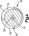
座屈部分70は、ボールスタッド10のシャンク部分に細長い溝72又は逃げ領域を形成することにより作られる。この溝72は、工作物を旋盤上で回転させるのと同様な仕方で形成されたものであるのがよい。かくして、座屈部分は、図示の実施形態では、円筒形外面74を備えた円形断面形状のものである。
ボールスタッド10の軸線52は、座屈部分70を通って延びている。しかしながら、座屈部分70の円筒形外面74の中心は、この軸線には一致していない。そうではなく、座屈部分70の円筒形外面74の中心は、軸線52から間隔を置いて位置する逃げ領域の中心線76に一致している。逃げ領域中心線76は、図示の実施形態では、軸線52に平行に延びている。その結果、座屈部分70(及び外面74)は、軸線52に対して偏心している。かくして、座屈部分70は、意図的に「曲げられて」軸線52から外れたボールスタッド10のシャンク部分50の部分となっている。
The buckled
The
座屈部分70について設けられる偏心の量は、製造された代表的なボールスタッド10の測定値に基づいて実験的に定められる。具体的には、統計学的に十分多くのボールスタッド10を測定してこれらのシャンク部分50の最も大きな偏心率、即ち、製造されたままのスタッドのシャンク部分で観察される「曲げ」の最大量を求める。この最大曲げ量は、製造された同様なボールスタッド10のどれにでも見られる最大偏心量であると見なされる。
次に、このように製造されたボールスタッド10の各々に、ボールスタッドの測定群で観察された最大偏心量よりも大きな偏心量を持つ座屈部分70を設ける。
The amount of eccentricity provided for the buckled
Next, each of the
その結果、これら製造されたボールスタッド10の座屈部分70は、軸方向圧縮荷重を受けて座屈する可能性が最も高いボールスタッドの部分であろう。ボールスタッド10は、座屈部分の偏心量が増大しているので、ボールスタッドの長さに沿う他の幾つかの場所とは異なり、座屈部分70で座屈するであろう。
したがって、ボールスタッド10のようなボールスタッドをタイロッド組立体26のようなタイロッド組立体に組み込むと、タイロッド組立体は、タイロッド組立体の長さに沿うどこか別の場所ではなく、これらの座屈部分70のところで座屈することになる。
加うるに、ボールスタッド10を座屈させるのに必要な力の大きさは、座屈部分70のところの偏心量で決まる。このようにして製造されたこの座屈部分70を備えるボールスタッド10は一つ一つ、座屈部分のところに同一の偏心量を有しているので、ボールスタッドは各々、同一所定の加えられた荷重を受けて座屈することになる。したがって、タイロッド組立体26の座屈特性、即ち座屈場所及び力の大きさは、あらかじめ知られている。
As a result, the buckled
Thus, when a ball stud, such as
In addition, the amount of force required to buckle the
本発明に従って構成された一ボールスタッド10では、ボールスタッド10のシャンク部分50の直径は、15.5ミリメートルである。座屈部分70の直径は、12.5ミリメートルである。座屈部分は、約0.15〜0.3ミリメートルだけ偏心している。
本発明は、種々の寸法のリンク機構部材、例えばボールスタッドに利用できる。かかるリンク機構部材は代表的には、直径が約12ミリメートル〜約21ミリメートルのシャンク部分を有する。なお、直径はこれとは異なっていてもよい。かかるボールスタッドの座屈部分の直径は、約8ミリメートル〜約18ミリメートルであるのがよい。座屈部分は、約0.1〜0.5ミリメートル以上偏心しているのがよい。座屈部分は、上記シャンク部分の直径の約1%〜約5%に等しい量だけ偏心しているのがよい。
In one
The present invention can be used for link mechanism members of various sizes, for example, ball studs. Such linkage members typically have a shank portion having a diameter of about 12 millimeters to about 21 millimeters. The diameter may be different from this. The diameter of the buckled portion of such a ball stud may be between about 8 millimeters and about 18 millimeters. The buckling portion may be eccentric about 0.1 to 0.5 millimeters or more. The buckled portion may be eccentric by an amount equal to about 1% to about 5% of the diameter of the shank portion.
本発明の上述の説明から、当業者であれば、本発明の改良例、変更例及び改造例を想到できよう。例えば、本発明は、操舵リンク機構部材だけでなくサスペンション用リンク機構部材にも利用できる。また、例えば、本発明は、円筒形リンク機構部材に座屈部分を形成することに限定されず、非円筒形の形をしたリンク機構部材にも利用できる。当業者の通常の創作能力の範囲内にあるかかる改良例、変更例及び改造例は、特許請求の範囲に記載された本発明の範囲に含まれる。 From the above description of the invention, those skilled in the art will perceive improvements, changes and modifications in the invention. For example, the present invention can be used not only for a steering link mechanism member but also for a suspension link mechanism member. Further, for example, the present invention is not limited to forming a buckled portion in a cylindrical link mechanism member, and can be used for a link mechanism member having a non-cylindrical shape. Such improvements, changes and modifications within the ordinary skill of a person skilled in the art are included within the scope of the invention as set forth in the appended claims.
Claims (17)
ソケットと、
このソケットに受け入れられ前記ソケットに対して回動自在に支持されたボール端部分を備えるスタッドとを有し、前記スタッドは長手方向軸線を有し、前記スタッドは、前記ソケットから突き出ていて、中心が前記軸線と一致したシャンク部分を有し、
前記ボールスタッドの前記シャンク部分は、所定の弱め部分を有し、前記所定の弱め部分は、この所定の弱め部分が設けられていなければ操舵装置それ自体を損傷させる力よりも小さい所定の軸線方向荷重を受けると座屈又は変形することができるように、この座屈又は変形の前の前記所定の弱め部分の中心軸線が前記スタッドの長手方向軸線に一致していない断面形状を有し、前記所定の弱め部分は、ほぼ直線状であり且つほぼ一様な断面形状の円形或いは楕円形を有することを特徴とするリンク機構部材。A link mechanism member incorporated in a vehicle steering link mechanism connected to a vehicle steering device,
Socket,
A stud with a ball end portion received in the socket and rotatably supported with respect to the socket, the stud having a longitudinal axis, the stud protruding from the socket and centered Has a shank portion coinciding with the axis,
The shank portion of the ball stud has a predetermined weakened portion, and the predetermined weakened portion has a predetermined axial direction that is smaller than a force that damages the steering device itself unless the predetermined weakened portion is provided. The center axis of the predetermined weakened portion prior to buckling or deformation has a cross-sectional shape that does not coincide with the longitudinal axis of the stud so that it can buckle or deform under load ; The link weakening member characterized in that the predetermined weakened portion is substantially linear and has a circular or elliptical shape with a substantially uniform cross-sectional shape.
第1の軸線に沿って軸線方向に延びるシャンクを有し、前記シャンクは、このシャンクの円周方向に全体的に延び且つ中心が前記第1の軸線に一致している第1の外面を有する第1の部分を有し、
前記シャンクは、前記第1の軸線に沿った所定の位置に細い第2の部分を有し、前記細い第2の部分は、前記第1の部分の断面積より小さい断面積を有し、前記シャンクは、前記細い第2の部分が設けられていない状態で操舵装置を損傷させる力よりも小さい所定の軸線方向荷重を受けると前記細い第2の部分で座屈するようになっており、
前記シャンクの前記細い第2の部分は、前記第1の部分の断面に対して突出しないように位置した第2の外面を有し、前記細い第2の部分は、第2の軸線に中心が一致しており、前記第2の軸線は、前記細い第2の部分が前記所定の軸線方向荷重を受けると座屈することができるように、前記細い第2の部分が座屈する前の状態では、前記第1の軸線に対してオフセットしており、前記細い第2の部分は、ほぼ直線状であり且つほぼ一様な断面形状の円形或いは楕円形を有し、
前記第1の外面は円筒形であり、前記第2の外面は、前記第1の軸線に関して前記第1の外面の半径方向内方に位置し、前記前記シャンクの前記細い第2の部分は、第1及び第2の両端部と、前記細い第2の部分の前記第1の端部で前記第2の外面を前記第2の外面に接続する第1の環状のテーパー面と、前記細い第2の部分の前記第2の端部で前記第1の外面を前記第2の外面に接続する第2の環状のテーパー面とを有し、前記第1及び第2の環状のテーパー面は、前記第1の軸線に対して非対称であることを特徴とするリンク機構部材。A link mechanism member incorporated in a vehicle steering link mechanism connected to a vehicle steering device,
A shank extending axially along a first axis, the shank having a first outer surface extending generally in the circumferential direction of the shank and having a center coincident with the first axis; Having a first part,
The shank has a thin second portion at a predetermined position along the first axis, and the thin second portion has a cross-sectional area smaller than a cross-sectional area of the first portion, The shank is designed to buckle at the thin second portion when it receives a predetermined axial load smaller than the force that damages the steering device in a state where the thin second portion is not provided.
The thin second portion of the shank has a second outer surface located so as not to protrude with respect to a cross section of the first portion, and the thin second portion is centered on a second axis. And the second axis is in a state before the thin second portion buckles so that the thin second portion can buckle when subjected to the predetermined axial load, Being offset with respect to the first axis, the thin second portion is substantially straight and has a substantially uniform cross-sectional circular or elliptical shape;
The first outer surface is cylindrical, the second outer surface is located radially inward of the first outer surface with respect to the first axis, and the thin second portion of the shank is First and second ends, a first annular tapered surface connecting the second outer surface to the second outer surface at the first end of the thin second portion, and the narrow first A second annular tapered surface connecting the first outer surface to the second outer surface at the second end of the second portion, the first and second annular tapered surfaces, A link mechanism member characterized by being asymmetric with respect to the first axis.
両端部を有すると共に第1の直線状軸線に沿って軸線方向に延びるシャンクを有し、前記シャンクは、第1の直線状軸線を有する第1の部分を有し、前記シャンクは、中心が前記第1の直線状軸線に一致した第1の円筒形外面を有する第1の部分を有し、
前記シャンクは、前記第1の直線状軸線に沿って前記シャンクの前記両端部の中間の所定の位置に細い第2の部分を有し、前記細い第2の部分は、前記第1の部分の断面積より小さい断面積を有し、前記シャンクは、前記細い第2の部分が設けられていない状態で操舵装置を損傷させる力よりも小さい所定の軸線方向荷重を受けると前記細い第2の部分で座屈するようになっており、
前記シャンクの前記細い第2の部分は、第2の直線状軸線に中心が一致した円形或いは楕円形の第2の外面を有し、前記第2の直線状軸線は、前記細い第2の部分が前記所定の軸線方向荷重を受けると座屈することができるように、前記細い第2の部分が座屈する前の状態では、前記第1の直線状軸線に対してオフセットし且つ前記第1の直線状軸線に平行に延びることを特徴とするリンク機構部材。A link mechanism member incorporated in a vehicle steering link mechanism connected to a vehicle steering device,
A shank having both ends and extending axially along a first linear axis, the shank having a first portion having a first linear axis, the shank being centered on the shank; Having a first portion having a first cylindrical outer surface coinciding with a first linear axis;
The shank has a thin second portion at a predetermined position in the middle of the both ends of the shank along the first linear axis, and the thin second portion is a portion of the first portion. The shank has a cross-sectional area smaller than the cross-sectional area, and the thin second portion is subjected to a predetermined axial load smaller than a force that damages the steering device in a state where the thin second portion is not provided. Buckled in,
The thin second portion of the shank has a circular or elliptical second outer surface centered on a second linear axis, and the second linear axis is the thin second portion. So as to be able to buckle when subjected to the predetermined axial load, in a state before the thin second portion buckles, the first straight line is offset with respect to the first linear axis. A link mechanism member extending in parallel to the axis.
第1及び第2の部分を有するシャンクを有し、前記第1の部分は、第1及び第2の両端部を有し且つ第1の軸線に沿って軸線方向に延び、前記第1の部分は、中心が前記第1の軸線に一致した第1の断面を有し、前記第1の断面は、円形或いは楕円形の断面形状を有し、
前記シャンクの前記第2の部分は、前記第1の部分の前記第1及び第2の両端部の中間に位置し、前記シャンクは、前記第2の部分が設けられていない状態で操舵装置を損傷させる力よりも小さい所定の軸線方向荷重を受けると前記細い第2の部分で座屈するようになっており、前記シャンクの前記第2の部分は、第2の断面を有し、この第2の断面の断面積は、前記第1の部分の断面積より小さくなっており、前記第2の断面は、前記細い第2の部分が座屈する前の状態では、前記第1の軸線に対してオフセットした第2の軸線に中心が一致し、前記第2の断面は、円形或いは楕円形の断面形状を有し、
前記シャンクの前記第2の部分を前記第1の部分の前記第1及び第2の両端部に接続する第1及び第2の移行部分をそれぞれ有し、各々の第1及び第2の移行部分は、前記第2の部分が前記所定の軸線方向荷重を受けると座屈することができるように、前記第1の軸線に沿って見ると、前記第1の軸線における第1の側の第1の距離にわたり、及び、前記第1の軸線における前記第1の側と反対側の第2の側で前記第1の距離とは異なる第2の距離にわたってそれぞれ軸線方向に延びる外面を有することを特徴とするリンク機構部材。A link mechanism member incorporated in a vehicle steering link mechanism connected to a vehicle steering device,
A shank having first and second portions, the first portion having first and second ends and extending axially along a first axis, the first portion; Has a first cross section whose center coincides with the first axis, and the first cross section has a circular or elliptical cross section,
The second portion of the shank is positioned between the first and second end portions of the first portion, and the shank operates the steering device in a state where the second portion is not provided. The thin second portion buckles when subjected to a predetermined axial load smaller than the damaging force, and the second portion of the shank has a second cross section, the second section. The cross-sectional area of the first cross-section is smaller than the cross-sectional area of the first portion, and the second cross-section is in relation to the first axis in a state before the thin second portion is buckled. The center coincides with the offset second axis, and the second cross-section has a circular or oval cross-sectional shape;
Each of the first and second transition portions includes first and second transition portions connecting the second portion of the shank to the first and second ends of the first portion, respectively. The first portion on the first side of the first axis when viewed along the first axis so that the second portion can buckle when subjected to the predetermined axial load. And having an outer surface extending in the axial direction over a distance and over a second distance different from the first distance on a second side of the first axis opposite the first side. Link mechanism member.
Applications Claiming Priority (3)
| Application Number | Priority Date | Filing Date | Title |
|---|---|---|---|
| US10/092,699 US7004485B2 (en) | 2002-03-07 | 2002-03-07 | Steering link with buckle portion |
| US10/092,699 | 2002-03-07 | ||
| PCT/US2003/005604 WO2003076254A1 (en) | 2002-03-07 | 2003-02-24 | Steering link with buckle portion |
Publications (3)
| Publication Number | Publication Date |
|---|---|
| JP2005526654A JP2005526654A (en) | 2005-09-08 |
| JP2005526654A5 JP2005526654A5 (en) | 2006-03-02 |
| JP4764603B2 true JP4764603B2 (en) | 2011-09-07 |
Family
ID=27787869
Family Applications (1)
| Application Number | Title | Priority Date | Filing Date |
|---|---|---|---|
| JP2003574488A Expired - Fee Related JP4764603B2 (en) | 2002-03-07 | 2003-02-24 | Steering link with buckling |
Country Status (12)
| Country | Link |
|---|---|
| US (1) | US7004485B2 (en) |
| EP (3) | EP1487686B1 (en) |
| JP (1) | JP4764603B2 (en) |
| KR (1) | KR20040097158A (en) |
| CN (1) | CN1692052B (en) |
| AT (3) | ATE490152T1 (en) |
| AU (1) | AU2003213265A1 (en) |
| CA (1) | CA2478583A1 (en) |
| DE (3) | DE60335227D1 (en) |
| MX (1) | MXPA04008534A (en) |
| PL (1) | PL373608A1 (en) |
| WO (1) | WO2003076254A1 (en) |
Families Citing this family (14)
| Publication number | Priority date | Publication date | Assignee | Title |
|---|---|---|---|---|
| US20060251853A1 (en) * | 2005-05-09 | 2006-11-09 | Ingram William O Iii | Method and apparatus for making carpet |
| US7547028B1 (en) * | 2007-01-08 | 2009-06-16 | Trw Automotive U.S. Llc | Tie rod steering linkage |
| JP4624456B2 (en) | 2008-09-26 | 2011-02-02 | トヨタ自動車株式会社 | Steel tie rod end and manufacturing method thereof |
| KR100966950B1 (en) | 2008-11-11 | 2010-06-30 | 현대위아 주식회사 | Assembly for knuckle and tie-rod for vehicle |
| DE102008061833A1 (en) * | 2008-12-11 | 2010-06-24 | Zf Friedrichshafen Ag | Wishbone of a motor vehicle |
| DE102009027736A1 (en) * | 2009-07-15 | 2011-01-27 | Zf Friedrichshafen Ag | Two-point link |
| DE102010011934A1 (en) * | 2010-03-18 | 2011-09-22 | Noell Mobile Systems Gmbh | Steering a portal stacker |
| JP5811397B2 (en) * | 2010-10-21 | 2015-11-11 | 株式会社ジェイテクト | Vehicle steering system |
| GB2492099B8 (en) * | 2011-06-21 | 2015-09-09 | Jaguar Land Rover Ltd | Vehicle components |
| FR2996199B1 (en) * | 2012-10-01 | 2015-05-15 | Jtekt Europe Sas | STEERING LINK WITH FLANGED REINFORCEMENT SLEEVE |
| US20150056001A1 (en) * | 2013-08-22 | 2015-02-26 | Powers and Sons, LLC | Mechanical overload fuse for steering linkage |
| US9500249B2 (en) * | 2015-03-09 | 2016-11-22 | The Boeing Company | Energy absorbing link |
| US10597077B2 (en) | 2018-05-07 | 2020-03-24 | Zf Friedrichshafen Ag | Buckling groove for inner tie rod ball joint studs |
| FR3138900A1 (en) * | 2022-08-22 | 2024-02-23 | ZF Lemförder Metal France | Steering element, steering system and associated method of manufacturing a steering element |
Citations (8)
| Publication number | Priority date | Publication date | Assignee | Title |
|---|---|---|---|---|
| JPH03209008A (en) * | 1989-10-12 | 1991-09-12 | Nacam | Rod |
| JPH0655237A (en) * | 1992-06-08 | 1994-03-01 | Rhythm Corp | Manufacture of steering tie rod |
| JPH07137642A (en) * | 1993-11-18 | 1995-05-30 | Toyota Motor Corp | Steering shaft |
| US5853194A (en) * | 1997-05-12 | 1998-12-29 | Trw Inc. | Collapsible steering shaft assembly |
| JPH11254932A (en) * | 1998-03-13 | 1999-09-21 | Tokai Rubber Ind Ltd | Bush mounting member |
| JPH11270607A (en) * | 1998-03-20 | 1999-10-05 | Tokai Rubber Ind Ltd | Member for bush installing |
| JPH11270608A (en) * | 1998-03-24 | 1999-10-05 | Tokai Rubber Ind Ltd | Member for bush installing |
| JPH11351233A (en) * | 1998-06-09 | 1999-12-24 | Somic Ishikawa:Kk | Ball stud, manufacture thereof, device thereof, and ball joint |
Family Cites Families (10)
| Publication number | Priority date | Publication date | Assignee | Title |
|---|---|---|---|---|
| US4162859A (en) * | 1977-12-27 | 1979-07-31 | Mcafee Loyd O | Vehicle steering knuckle arm angle compensator |
| DE2845345A1 (en) * | 1978-10-18 | 1980-04-30 | Daimler Benz Ag | INDEPENDENT FRONT SUSPENSION FOR MOTOR VEHICLES |
| JPS5996058A (en) * | 1982-11-22 | 1984-06-02 | Mitsubishi Electric Corp | Shock absorbing steering shaft |
| US4887486A (en) * | 1988-02-22 | 1989-12-19 | Trw, Inc. | Linkage component |
| CN2066411U (en) * | 1990-03-30 | 1990-11-28 | 浙江省玉环县坎门航海机械厂 | Connector for track rod of adjusting type beijing 130 |
| JPH0575064U (en) * | 1991-11-01 | 1993-10-12 | 株式会社リズム | Tie rod for steering linkage |
| JPH0737862U (en) * | 1993-12-24 | 1995-07-14 | 株式会社リズム | Tie rod structure of vehicle steering system |
| US5697478A (en) * | 1996-09-09 | 1997-12-16 | Boeing North American, Inc. | Sacrifical tube shock attenuation |
| US6298962B1 (en) * | 1998-03-13 | 2001-10-09 | Showa Denko K.K. | Member for arm |
| GB2339750B (en) * | 1998-07-24 | 2001-02-07 | Toyoda Automatic Loom Works | Steering device for vehicle |
-
2002
- 2002-03-07 US US10/092,699 patent/US7004485B2/en not_active Expired - Fee Related
-
2003
- 2003-02-24 DE DE60335227T patent/DE60335227D1/en not_active Expired - Lifetime
- 2003-02-24 EP EP03709314A patent/EP1487686B1/en not_active Expired - Lifetime
- 2003-02-24 AT AT08014948T patent/ATE490152T1/en not_active IP Right Cessation
- 2003-02-24 CN CN038085623A patent/CN1692052B/en not_active Expired - Fee Related
- 2003-02-24 AT AT08014949T patent/ATE465067T1/en not_active IP Right Cessation
- 2003-02-24 KR KR10-2004-7013978A patent/KR20040097158A/en not_active Application Discontinuation
- 2003-02-24 MX MXPA04008534A patent/MXPA04008534A/en active IP Right Grant
- 2003-02-24 AU AU2003213265A patent/AU2003213265A1/en not_active Abandoned
- 2003-02-24 JP JP2003574488A patent/JP4764603B2/en not_active Expired - Fee Related
- 2003-02-24 WO PCT/US2003/005604 patent/WO2003076254A1/en active Application Filing
- 2003-02-24 PL PL03373608A patent/PL373608A1/en not_active Application Discontinuation
- 2003-02-24 CA CA002478583A patent/CA2478583A1/en not_active Abandoned
- 2003-02-24 DE DE60332294T patent/DE60332294D1/en not_active Expired - Lifetime
- 2003-02-24 EP EP08014948A patent/EP2000391B1/en not_active Expired - Lifetime
- 2003-02-24 EP EP08014949A patent/EP1995154B1/en not_active Expired - Lifetime
- 2003-02-24 DE DE60330953T patent/DE60330953D1/en not_active Expired - Lifetime
- 2003-02-24 AT AT03709314T patent/ATE455024T1/en not_active IP Right Cessation
Patent Citations (8)
| Publication number | Priority date | Publication date | Assignee | Title |
|---|---|---|---|---|
| JPH03209008A (en) * | 1989-10-12 | 1991-09-12 | Nacam | Rod |
| JPH0655237A (en) * | 1992-06-08 | 1994-03-01 | Rhythm Corp | Manufacture of steering tie rod |
| JPH07137642A (en) * | 1993-11-18 | 1995-05-30 | Toyota Motor Corp | Steering shaft |
| US5853194A (en) * | 1997-05-12 | 1998-12-29 | Trw Inc. | Collapsible steering shaft assembly |
| JPH11254932A (en) * | 1998-03-13 | 1999-09-21 | Tokai Rubber Ind Ltd | Bush mounting member |
| JPH11270607A (en) * | 1998-03-20 | 1999-10-05 | Tokai Rubber Ind Ltd | Member for bush installing |
| JPH11270608A (en) * | 1998-03-24 | 1999-10-05 | Tokai Rubber Ind Ltd | Member for bush installing |
| JPH11351233A (en) * | 1998-06-09 | 1999-12-24 | Somic Ishikawa:Kk | Ball stud, manufacture thereof, device thereof, and ball joint |
Also Published As
| Publication number | Publication date |
|---|---|
| EP1487686A4 (en) | 2007-09-26 |
| ATE490152T1 (en) | 2010-12-15 |
| EP1487686A1 (en) | 2004-12-22 |
| DE60335227D1 (en) | 2011-01-13 |
| CN1692052A (en) | 2005-11-02 |
| CN1692052B (en) | 2010-06-16 |
| US20030168826A1 (en) | 2003-09-11 |
| US7004485B2 (en) | 2006-02-28 |
| DE60330953D1 (en) | 2010-03-04 |
| EP2000391A3 (en) | 2008-12-17 |
| EP1995154B1 (en) | 2010-04-21 |
| EP2000391B1 (en) | 2010-12-01 |
| PL373608A1 (en) | 2005-09-05 |
| AU2003213265A1 (en) | 2003-09-22 |
| WO2003076254A1 (en) | 2003-09-18 |
| EP1995154A1 (en) | 2008-11-26 |
| EP1487686B1 (en) | 2010-01-13 |
| DE60332294D1 (en) | 2010-06-02 |
| ATE455024T1 (en) | 2010-01-15 |
| ATE465067T1 (en) | 2010-05-15 |
| EP2000391A2 (en) | 2008-12-10 |
| KR20040097158A (en) | 2004-11-17 |
| JP2005526654A (en) | 2005-09-08 |
| MXPA04008534A (en) | 2005-07-13 |
| CA2478583A1 (en) | 2003-09-18 |
Similar Documents
| Publication | Publication Date | Title |
|---|---|---|
| JP4764603B2 (en) | Steering link with buckling | |
| US5603583A (en) | Tie rod assembly for vehicle steering linkages | |
| US7850178B2 (en) | Motor vehicle adjustable toe link | |
| JPH0891230A (en) | Manufacture of impact absorbing type steering shaft | |
| US20100038167A1 (en) | Toothed rack or threaded rod | |
| JP2009040302A (en) | Energy absorption type shaft for steering device | |
| US7604428B2 (en) | Mounting assembly for drive shafts in universal joint yokes | |
| US6745610B2 (en) | Method of manufacturing arm | |
| US20110192250A1 (en) | Rack bar supporting device of steering apparatus for vehicle | |
| US20050111908A1 (en) | Tie rod end | |
| US10597077B2 (en) | Buckling groove for inner tie rod ball joint studs | |
| JP3698626B2 (en) | Steering device and fitting used therefor | |
| US11267304B2 (en) | Linkage including compressible bushings and a method of installing | |
| JPS6157419A (en) | Stabilizer for vehicle | |
| US6623363B2 (en) | Universal joint yoke and method of making same | |
| JPH05170128A (en) | Manufacture of tie rod bar | |
| AU2019100726A4 (en) | Automotive steering linkage end | |
| JPH0714123Y2 (en) | Tie rod for steering linkage | |
| JPH0737862U (en) | Tie rod structure of vehicle steering system | |
| GB2338199A (en) | Extensible wheel brace | |
| JP3712540B2 (en) | Power transmission device capable of absorbing shock | |
| JPH03210928A (en) | Pipe expander | |
| JPS6177508A (en) | Radius rod for car | |
| JPS631651Y2 (en) | ||
| JP2003011842A (en) | Vehicular steering device |
Legal Events
| Date | Code | Title | Description |
|---|---|---|---|
| A521 | Request for written amendment filed |
Free format text: JAPANESE INTERMEDIATE CODE: A523 Effective date: 20060110 |
|
| A621 | Written request for application examination |
Free format text: JAPANESE INTERMEDIATE CODE: A621 Effective date: 20060110 |
|
| A131 | Notification of reasons for refusal |
Free format text: JAPANESE INTERMEDIATE CODE: A131 Effective date: 20080421 |
|
| A601 | Written request for extension of time |
Free format text: JAPANESE INTERMEDIATE CODE: A601 Effective date: 20080722 |
|
| A602 | Written permission of extension of time |
Free format text: JAPANESE INTERMEDIATE CODE: A602 Effective date: 20080729 |
|
| A131 | Notification of reasons for refusal |
Free format text: JAPANESE INTERMEDIATE CODE: A131 Effective date: 20090302 |
|
| A521 | Request for written amendment filed |
Free format text: JAPANESE INTERMEDIATE CODE: A523 Effective date: 20090527 |
|
| A131 | Notification of reasons for refusal |
Free format text: JAPANESE INTERMEDIATE CODE: A131 Effective date: 20091130 |
|
| A521 | Request for written amendment filed |
Free format text: JAPANESE INTERMEDIATE CODE: A523 Effective date: 20100225 |
|
| A131 | Notification of reasons for refusal |
Free format text: JAPANESE INTERMEDIATE CODE: A131 Effective date: 20100906 |
|
| A521 | Request for written amendment filed |
Free format text: JAPANESE INTERMEDIATE CODE: A523 Effective date: 20101203 |
|
| TRDD | Decision of grant or rejection written | ||
| A01 | Written decision to grant a patent or to grant a registration (utility model) |
Free format text: JAPANESE INTERMEDIATE CODE: A01 Effective date: 20110523 |
|
| A01 | Written decision to grant a patent or to grant a registration (utility model) |
Free format text: JAPANESE INTERMEDIATE CODE: A01 |
|
| A61 | First payment of annual fees (during grant procedure) |
Free format text: JAPANESE INTERMEDIATE CODE: A61 Effective date: 20110613 |
|
| FPAY | Renewal fee payment (event date is renewal date of database) |
Free format text: PAYMENT UNTIL: 20140617 Year of fee payment: 3 |
|
| R150 | Certificate of patent or registration of utility model |
Free format text: JAPANESE INTERMEDIATE CODE: R150 |
|
| R250 | Receipt of annual fees |
Free format text: JAPANESE INTERMEDIATE CODE: R250 |
|
| LAPS | Cancellation because of no payment of annual fees |