EP1995154B1 - Steering link with buckle portion - Google Patents
Steering link with buckle portion Download PDFInfo
- Publication number
- EP1995154B1 EP1995154B1 EP08014949A EP08014949A EP1995154B1 EP 1995154 B1 EP1995154 B1 EP 1995154B1 EP 08014949 A EP08014949 A EP 08014949A EP 08014949 A EP08014949 A EP 08014949A EP 1995154 B1 EP1995154 B1 EP 1995154B1
- Authority
- EP
- European Patent Office
- Prior art keywords
- axis
- ball stud
- socket
- ball
- buckle
- Prior art date
- Legal status (The legal status is an assumption and is not a legal conclusion. Google has not performed a legal analysis and makes no representation as to the accuracy of the status listed.)
- Expired - Lifetime
Links
- 230000000712 assembly Effects 0.000 description 3
- 238000000429 assembly Methods 0.000 description 3
- 239000012530 fluid Substances 0.000 description 3
- 238000005452 bending Methods 0.000 description 2
- 238000012986 modification Methods 0.000 description 2
- 230000004048 modification Effects 0.000 description 2
- 229910000975 Carbon steel Inorganic materials 0.000 description 1
- 229910000831 Steel Inorganic materials 0.000 description 1
- 239000010962 carbon steel Substances 0.000 description 1
- 238000010276 construction Methods 0.000 description 1
- 230000001419 dependent effect Effects 0.000 description 1
- 230000000694 effects Effects 0.000 description 1
- 238000004519 manufacturing process Methods 0.000 description 1
- 239000000463 material Substances 0.000 description 1
- 238000005259 measurement Methods 0.000 description 1
- 238000000034 method Methods 0.000 description 1
- 238000005096 rolling process Methods 0.000 description 1
- 239000010959 steel Substances 0.000 description 1
- 239000000725 suspension Substances 0.000 description 1
Images

Classifications
-
- B—PERFORMING OPERATIONS; TRANSPORTING
- B62—LAND VEHICLES FOR TRAVELLING OTHERWISE THAN ON RAILS
- B62D—MOTOR VEHICLES; TRAILERS
- B62D7/00—Steering linkage; Stub axles or their mountings
- B62D7/20—Links, e.g. track rods
-
- B—PERFORMING OPERATIONS; TRANSPORTING
- B60—VEHICLES IN GENERAL
- B60G—VEHICLE SUSPENSION ARRANGEMENTS
- B60G2206/00—Indexing codes related to the manufacturing of suspensions: constructional features, the materials used, procedures or tools
- B60G2206/01—Constructional features of suspension elements, e.g. arms, dampers, springs
- B60G2206/016—Constructional features of suspension elements, e.g. arms, dampers, springs allowing controlled deformation during collision
-
- B—PERFORMING OPERATIONS; TRANSPORTING
- B60—VEHICLES IN GENERAL
- B60G—VEHICLE SUSPENSION ARRANGEMENTS
- B60G2206/00—Indexing codes related to the manufacturing of suspensions: constructional features, the materials used, procedures or tools
- B60G2206/01—Constructional features of suspension elements, e.g. arms, dampers, springs
- B60G2206/10—Constructional features of arms
- B60G2206/11—Constructional features of arms the arm being a radius or track or torque or steering rod or stabiliser end link
- B60G2206/111—Constructional features of arms the arm being a radius or track or torque or steering rod or stabiliser end link of adjustable length
- B60G2206/1112—Manually, for alignment purposes
-
- Y—GENERAL TAGGING OF NEW TECHNOLOGICAL DEVELOPMENTS; GENERAL TAGGING OF CROSS-SECTIONAL TECHNOLOGIES SPANNING OVER SEVERAL SECTIONS OF THE IPC; TECHNICAL SUBJECTS COVERED BY FORMER USPC CROSS-REFERENCE ART COLLECTIONS [XRACs] AND DIGESTS
- Y10—TECHNICAL SUBJECTS COVERED BY FORMER USPC
- Y10T—TECHNICAL SUBJECTS COVERED BY FORMER US CLASSIFICATION
- Y10T403/00—Joints and connections
- Y10T403/32—Articulated members
- Y10T403/32606—Pivoted
- Y10T403/32631—Universal ball and socket
Abstract
Description
- The present invention relates to a linkage member having a portion that is designed to buckle under a predetermined axial load.
- A vehicle steering linkage includes one or more links that connect the steering gear with the steerable wheels of the vehicle. For example, a vehicle having a rack and pinion steering gear includes, at each end of the rack, an inner tie rod that is connected for movement with the rack, and an outer tie rod that is connected for movement with the steering knuckle. The inner and outer tie rods are connected with each other in a known manner to form a tie rod assembly. The length of the tie rod assembly is adjustable, to enable adjustment of vehicle toe.
- If the vehicle engages a roadway curb at a high enough rate of speed, or if a curb push-off is attempted, force is transmitted from the steerable wheel back through the steering linkage to the steering gear. The steering gear can be damaged is sufficient force is transmitted.
- To prevent such damage, it is known to provide a tie rod assembly with a predetermined weakened portion. The predetermined weakened portion is designed to buckle, or deform, at a force level lower than the amount of force that would damage the steering gear itself.
-
U.S. Patent No. 6,234,704 discloses a ball stud having a buckle portion designed to buckle under an appropriate amount of longitudinal pressure. The buckle portion is formed by a rolling process resulting in furrowed portions and raised portions integrally formed in an accordion shape along a portion of the ball stud. - It is also known to form, on a cylindrical steering link, a reduced diameter cylindrical portion of the link. The reduced diameter portion, because it has a narrower cross-section than the remainder of the link, forms a predetermined weakened portion, or buckle portion, of the steering link.
- Document
DE19911121 discloses the preamble of claim 1, having a linkage member which has a deformed and/or bent weakened portion. - In a first aspect of the invention there is provided a vehicle steering linkage member, said linkage member comprises; a socket; and a stud having a ball end portion received in said socket and supported for pivotal movement relative to said socket, said stud having a longitudinal axis, said stud having a shank portion projecting from said socket and centered on said axis ; said shank portion of said ball stud including a predetermined weakened portion, said predetermined weakened portion buckling under a predetermined amount of force and has a cross-sectional configuration that is not centered on said longitudinal axis and characterised in that said predetermined weakened portion cross-sectional configuration is eccentric to said longitudinal axis by a distance that is greater than the largest amount of eccentricity observed in said shank portion of said ball stud.
- The foregoing and other features of the present invention will become apparent to one skilled in the art to which the present invention relates upon consideration of the following description of the invention with reference to the accompanying drawings, in which:
-
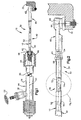
Fig. 1 is a schematic illustration of a portion of a vehicle steering assembly including a rack and pinion steering gear and a linkage member in accordance with the present invention; -
Fig. 2 is an enlarged view of a portion of the linkage member ofFig. 1 ; -
Fig. 2 is a further enlarged view of a buckle portion of the linkage member ofFig. 1 ; and -
Fig. 4 is a sectional view through the buckle portion ofFig. 3 , taken along line 4-4 ofFig. 3 . - The present invention relates to a linkage member having a portion that is designed to buckle under a predetermined axial load. The present invention is applicable to various linkage constructions. As representative of the present invention,
Fig. 1 illustrates alinkage member 10 that is incorporated in avehicle steering linkage 12. - The
linkage 12 is connected with a fluid power assisted rack andpinion steering gear 14. It should be understood that the present invention is applicable to steering linkage that is used with different types of steering gear. - The
steering gear 14 includes ahousing 16, a pinion 18, and arack 20. The rack extends longitudinally through thehousing 16. Thehousing 16 partially defines a fluid chamber in which is located a piston (not shown) fixed to therack 20. Therack 20 is supported for axial movement relative to thehousing 16. Upon rotation of the vehicle steering wheel 26, fluid under pressure is directed against the piston, causing therack 20 to move within thehousing 16 in a direction parallel to asteering axis 24. Axial movement of therack 20 moves thesteering linkage 12 connected to the ends of the rack. - The vehicle steering linkage 12 (
Figs. 1 and 2 ) includes atie rod assembly 30 that extends between and interconnects one end of therack 20 and a steering knuckle, a portion of which is shown at 32. Thesteering knuckle 32 is connected with a steerable wheel (not shown) of the vehicle. Thus, when thesteering gear 14 is actuated, thetie rod assembly 30 transmits force from therack 20 to thesteering knuckle 32 to effect steering movement of the steerable wheel. - The
tie rod assembly 30 includes aninner tie rod 40 and anouter tie rod 60. Theinner tie rod 40 includes asocket 42 and also includes thelinkage member 10, which is formed as a ball stud. Thesocket 42 has a threadedend portion 44 that is screwed into therack 20. Thesocket 42 is thus fixed for movement with therack 20. Thesocket 42 defines apivot center 46 for theball stud 10. - The
ball stud 10 is preferably made as one piece from a single, homogeneous piece of material, such as carbon steel. Theball stud 10 may be formed by cold heading and heat treating of a steel rod. - The
ball stud 10 has aball end portion 48 and ashank portion 50. Theball end portion 48 of theball stud 10 is received in the socket. Theball end portion 48 of theball stud 10 supports the ball stud on therack 20 for pivotal movement relative to the rack about thepivot center 46. - The
ball stud 10 has alongitudinal axis 52 that extends through the center of theball end portion 48 and through thepivot center 46 of thesocket 42. Theball stud axis 52 may be coincident with thesteering axis 24, as shown inFig. 1 , or may be skewed relative to the steering axis when thetie rod assembly 30 is moved relative to therack 20 about thepivot center 46. Theshank portion 50 of theball stud 10 extends from theball end portion 48. Theshank portion 50 has a cylindrical, rod-shaped configuration centered on theaxis 52. Theshank portion 50 has a threadedouter end portion 54, opposite theball end portion 48. - The
outer tie rod 60 has anouter end portion 62 that is formed as a ball joint for connection with thesteering knuckle 32. Theball joint 62 has apivot center 64 for theouter tie rod 60. Aninner end portion 66 of theouter tie rod 60 is formed as an internally threaded sleeve. The externally threadedend portion 54 of theball stud 10 is screwed into the internally threadedend portion 66 of theouter tie rod 60, to secure the two pieces together. Ajam nut 68 on theouter tie rod 60 locks the two pieces together. - The tie rod assembly 26 thus extends between the
rack 20 and thesteering knuckle 32. The tie rod assembly 26 interconnects the rack 80 and thesteering knuckle 32 in a force-transmitting relationship. The length of the tie rod assembly 26 is adjustable by loosening thejam nut 68, rotating theball stud 10 of theinner tie rod 40 relative to thesocket 42 and to theouter tie rod 60, and retightening the jam nut. - The
shank portion 50 of theball stud 10 has a substantially uniform diameter along its length, centered on theaxis 52. However, theshank portion 50 may not be perfectly straight along its entire length, primarily because of the heat-treating process applied during manufacture of theball stud 10. Thus, there may be sections along the length of theshank portion 50 of theball stud 10 that are "bent" off theaxis 52, that is, not perfectly centered on the axis. - If sufficient compressive force is applied along the
axis 52 of theball stud 10, as may occur during use of the vehicle as discussed above, theshank portion 50 will tend to buckle. This buckling will occur at the section along theaxis 52 where theshank portion 50 is farthest from being centered on the axis, that is, where it is most "bent" off theaxis 52. - It is desirable to control the location of buckling of the
shank portion 50, that is, to ensure that it buckles, if at all, at a predetermined location along its length. In addition, it is desirable to control the amount of force needed to make the linkage member, i.e., theball stud 10 buckle. - To this end, the shank portion of the
ball stud 10 is provided with a predetermined weakened portion, or buckle portion 70 (also known as a "fuse"). Preferably, thebuckle portion 70 of theball stud 10 is located at about the axial center (from end to end) of the tie rod assembly 26. Thebuckle portion 70 is provided in an area of theshank portion 50 that has a circular cross-sectional configuration, with a cylindricalouter surface 71. - The
buckle portion 70 is formed by creating anelongate groove 72, or relief area, on theshank portion 50 of theball stud 10. Thisgroove 72 may be formed in a manner similar to turning a work piece on a lathe. The buckle portion in the illustrated embodiment thus has a circular cross-sectional configuration, with a cylindricalouter surface 74. - The
axis 52 of theball stud 10 extends through thebuckle portion 70. The cylindricalouter surface 74 of thebuckle portion 70 is not, however, centered on the axis. Rather, the cylindricalouter surface 74 of thebuckle portion 70 is centered on arelief centerline 76 that is spaced apart from theaxis 52. Therelief centerline 76, in the illustrated embodiment, extends parallel to theaxis 52. As a result, the buckle portion 70 (and the outer surface 74) are eccentric to theaxis 52. Thebuckle portion 70 thus constitutes a section of theshank portion 50 of theball stud 10 that is intentionally "bent" off theaxis 52. - The amount of eccentricity that is provided for the
buckle portion 70 is empirically determined on the basis of measurements of typical manufacturedball studs 10. Specifically, a statistically large enough number ofball studs 10 are measured to determine the largest eccentricity of theirshank portions 50, that is, the maximum amount of "bending" observed in the shank portions of the studs as manufactured. This maximum amount of bending is deemed to be the greatest amount of eccentricity that will be found in any similar manufacturedball stud 10. - Each one of the
ball studs 10 that is manufactured in this way is then provided with abuckle portion 70 having an amount of eccentricity that is larger than the largest amount of eccentricity observed in the measured group of ball studs. - As a result, the
buckle portions 70 of these manufacturedball studs 10 will be the portions of the ball studs that are most likely to buckle under axial compressive load. Theball studs 10 will buckle at thebuckle portions 70, as opposed to at some other location along the length of the ball studs, because of the increased eccentricity of the buckle portions. - Therefore, when ball studs like the
ball stud 10 are incorporated into tie rod assemblies like the tie rod assembly 26, the tie rod assemblies will buckle at theirbuckle portions 70, rather than elsewhere along the length of the tie rod assemblies. - In addition, the amount of force needed to buckle the
ball stud 10 is dependent on the amount of eccentricity at thebuckle portion 70. Because eachsingle ball stud 10 manufactured in this way with thisbuckle portion 70 has the same amount of eccentricity at the buckle portion, each one of the ball studs will buckle under the same, predetermined, applied load. Therefore, the buckling characteristics of the tie rod assembly 26 are known in advance-location, and amount of force. - In one
ball stud 10 constructed in accordance with the invention, theshank portion 50 of the ball stud has a diameter of 15.5 millimeters. Thebuckle portion 70 has a diameter of 12.5 millimeters. The buckle portion is eccentric by about 0.15 to 0.3 millimeters. - The invention is applicable to linkage members, such as ball studs, having different dimensions. Such linkage members typically have a shank portion with a diameter in the range of from about 12 millimeters to about 21 millimeters, although the diameter could be different. The buckle portion of such a ball stud may have a diameter in the range of from about 8 millimeters to about 18 millimeters. The buckle portion may be eccentric by about 0.1 to 0.5 millimeters, or more. The buckle portion may be eccentric by an amount equal to about 1% to about 5% of the diameter of said shank portion.
- From the foregoing description of the invention, those skilled in the art will perceive improvements, changes and modifications in the invention. For example, the invention could be used for a suspension linkage member as well as a steering linkage member. Also, for example, the invention is not limited to forming a buckle portion on a cylindrical linkage member, but is usable also with linkage members having non-cylindrical configurations. Such improvements, changes and modifications within the skill of the art are intended to be covered by the appended claims.
Claims (4)
- A vehicle steering linkage member (12), said linkage member comprises; a socket (42); and a ball stud (10) having a ball end portion (48) received in said socket and supported for pivotal movement relative to said socket, said stud having a longitudinal axis (52), said stud having a shank portion (50) projecting from said socket and centered on said axis ; said shank portion of said ball stud including a predetermined weakened portion, said predetermined weakened portion (70) buckling under a predetermined amount of force and has a cross-sectional configuration that is not centered on said longitudinal axis characterised in that said predetermined weakened portion has a circular cross-sectional configuration having a reduced diameter.
- A linkage member as set forth in claim 1 characterised in that said shank portion of said ball stud has a circular cross-sectional configuration centered on said axis.
- A linkage member as set forth in claim 1 characterised in that said shank portion of said ball stud has a circular cross-sectional configuration centered on said axis and said predetermined weakened portion has a circular cross-sectional configuration that is not centered on said axis.
- A linkage member as set forth in claim 3 characterised in that said shank portion of said ball stud has a circular cross-sectional configuration centered on said axis and said predetermined weakened portion has a circular cross-sectional configuration.
Applications Claiming Priority (2)
| Application Number | Priority Date | Filing Date | Title |
|---|---|---|---|
| US10/092,699 US7004485B2 (en) | 2002-03-07 | 2002-03-07 | Steering link with buckle portion |
| EP03709314A EP1487686B1 (en) | 2002-03-07 | 2003-02-24 | Steering link with buckle portion |
Related Parent Applications (2)
| Application Number | Title | Priority Date | Filing Date |
|---|---|---|---|
| EP03709314.3 Division | 2003-02-24 | ||
| EP03709314A Division EP1487686B1 (en) | 2002-03-07 | 2003-02-24 | Steering link with buckle portion |
Publications (2)
| Publication Number | Publication Date |
|---|---|
| EP1995154A1 EP1995154A1 (en) | 2008-11-26 |
| EP1995154B1 true EP1995154B1 (en) | 2010-04-21 |
Family
ID=27787869
Family Applications (3)
| Application Number | Title | Priority Date | Filing Date |
|---|---|---|---|
| EP03709314A Expired - Lifetime EP1487686B1 (en) | 2002-03-07 | 2003-02-24 | Steering link with buckle portion |
| EP08014949A Expired - Lifetime EP1995154B1 (en) | 2002-03-07 | 2003-02-24 | Steering link with buckle portion |
| EP08014948A Expired - Lifetime EP2000391B1 (en) | 2002-03-07 | 2003-02-24 | Steering link with buckle portion |
Family Applications Before (1)
| Application Number | Title | Priority Date | Filing Date |
|---|---|---|---|
| EP03709314A Expired - Lifetime EP1487686B1 (en) | 2002-03-07 | 2003-02-24 | Steering link with buckle portion |
Family Applications After (1)
| Application Number | Title | Priority Date | Filing Date |
|---|---|---|---|
| EP08014948A Expired - Lifetime EP2000391B1 (en) | 2002-03-07 | 2003-02-24 | Steering link with buckle portion |
Country Status (12)
| Country | Link |
|---|---|
| US (1) | US7004485B2 (en) |
| EP (3) | EP1487686B1 (en) |
| JP (1) | JP4764603B2 (en) |
| KR (1) | KR20040097158A (en) |
| CN (1) | CN1692052B (en) |
| AT (3) | ATE490152T1 (en) |
| AU (1) | AU2003213265A1 (en) |
| CA (1) | CA2478583A1 (en) |
| DE (3) | DE60330953D1 (en) |
| MX (1) | MXPA04008534A (en) |
| PL (1) | PL373608A1 (en) |
| WO (1) | WO2003076254A1 (en) |
Families Citing this family (14)
| Publication number | Priority date | Publication date | Assignee | Title |
|---|---|---|---|---|
| US20060251853A1 (en) * | 2005-05-09 | 2006-11-09 | Ingram William O Iii | Method and apparatus for making carpet |
| US7547028B1 (en) * | 2007-01-08 | 2009-06-16 | Trw Automotive U.S. Llc | Tie rod steering linkage |
| JP4624456B2 (en) * | 2008-09-26 | 2011-02-02 | トヨタ自動車株式会社 | Steel tie rod end and manufacturing method thereof |
| KR100966950B1 (en) | 2008-11-11 | 2010-06-30 | 현대위아 주식회사 | Assembly for knuckle and tie-rod for vehicle |
| DE102008061833A1 (en) * | 2008-12-11 | 2010-06-24 | Zf Friedrichshafen Ag | Wishbone of a motor vehicle |
| DE102009027736A1 (en) * | 2009-07-15 | 2011-01-27 | Zf Friedrichshafen Ag | Two-point link |
| DE102010011934A1 (en) * | 2010-03-18 | 2011-09-22 | Noell Mobile Systems Gmbh | Steering a portal stacker |
| JP5811397B2 (en) * | 2010-10-21 | 2015-11-11 | 株式会社ジェイテクト | Vehicle steering system |
| GB2492099B8 (en) * | 2011-06-21 | 2015-09-09 | Jaguar Land Rover Ltd | Vehicle components |
| FR2996199B1 (en) * | 2012-10-01 | 2015-05-15 | Jtekt Europe Sas | STEERING LINK WITH FLANGED REINFORCEMENT SLEEVE |
| US20150056001A1 (en) * | 2013-08-22 | 2015-02-26 | Powers and Sons, LLC | Mechanical overload fuse for steering linkage |
| US9500249B2 (en) * | 2015-03-09 | 2016-11-22 | The Boeing Company | Energy absorbing link |
| US10597077B2 (en) | 2018-05-07 | 2020-03-24 | Zf Friedrichshafen Ag | Buckling groove for inner tie rod ball joint studs |
| FR3138900A1 (en) * | 2022-08-22 | 2024-02-23 | ZF Lemförder Metal France | Steering element, steering system and associated method of manufacturing a steering element |
Family Cites Families (18)
| Publication number | Priority date | Publication date | Assignee | Title |
|---|---|---|---|---|
| US4162859A (en) * | 1977-12-27 | 1979-07-31 | Mcafee Loyd O | Vehicle steering knuckle arm angle compensator |
| DE2845345A1 (en) * | 1978-10-18 | 1980-04-30 | Daimler Benz Ag | INDEPENDENT FRONT SUSPENSION FOR MOTOR VEHICLES |
| JPS5996058A (en) * | 1982-11-22 | 1984-06-02 | Mitsubishi Electric Corp | Shock absorbing steering shaft |
| US4887486A (en) * | 1988-02-22 | 1989-12-19 | Trw, Inc. | Linkage component |
| FR2653190B1 (en) * | 1989-10-12 | 1994-11-18 | Nacam | REINFORCED FLAMING APTITUDE BAR AND ITS APPLICATION IN PARTICULAR TO DIRECTIONS OF AUTOMOBILES. |
| CN2066411U (en) * | 1990-03-30 | 1990-11-28 | 浙江省玉环县坎门航海机械厂 | Connector for track rod of adjusting type beijing 130 |
| JPH0575064U (en) * | 1991-11-01 | 1993-10-12 | 株式会社リズム | Tie rod for steering linkage |
| JPH0655237A (en) * | 1992-06-08 | 1994-03-01 | Rhythm Corp | Manufacture of steering tie rod |
| JPH07137642A (en) * | 1993-11-18 | 1995-05-30 | Toyota Motor Corp | Steering shaft |
| JPH0737862U (en) * | 1993-12-24 | 1995-07-14 | 株式会社リズム | Tie rod structure of vehicle steering system |
| US5697478A (en) * | 1996-09-09 | 1997-12-16 | Boeing North American, Inc. | Sacrifical tube shock attenuation |
| US5853194A (en) * | 1997-05-12 | 1998-12-29 | Trw Inc. | Collapsible steering shaft assembly |
| JPH11270607A (en) * | 1998-03-20 | 1999-10-05 | Tokai Rubber Ind Ltd | Member for bush installing |
| JPH11270608A (en) * | 1998-03-24 | 1999-10-05 | Tokai Rubber Ind Ltd | Member for bush installing |
| JPH11254932A (en) * | 1998-03-13 | 1999-09-21 | Tokai Rubber Ind Ltd | Bush mounting member |
| US6298962B1 (en) * | 1998-03-13 | 2001-10-09 | Showa Denko K.K. | Member for arm |
| JPH11351233A (en) * | 1998-06-09 | 1999-12-24 | Somic Ishikawa:Kk | Ball stud, manufacture thereof, device thereof, and ball joint |
| GB2339750B (en) * | 1998-07-24 | 2001-02-07 | Toyoda Automatic Loom Works | Steering device for vehicle |
-
2002
- 2002-03-07 US US10/092,699 patent/US7004485B2/en not_active Expired - Fee Related
-
2003
- 2003-02-24 AT AT08014948T patent/ATE490152T1/en not_active IP Right Cessation
- 2003-02-24 PL PL03373608A patent/PL373608A1/en not_active Application Discontinuation
- 2003-02-24 EP EP03709314A patent/EP1487686B1/en not_active Expired - Lifetime
- 2003-02-24 AU AU2003213265A patent/AU2003213265A1/en not_active Abandoned
- 2003-02-24 MX MXPA04008534A patent/MXPA04008534A/en active IP Right Grant
- 2003-02-24 AT AT08014949T patent/ATE465067T1/en not_active IP Right Cessation
- 2003-02-24 DE DE60330953T patent/DE60330953D1/en not_active Expired - Lifetime
- 2003-02-24 EP EP08014949A patent/EP1995154B1/en not_active Expired - Lifetime
- 2003-02-24 DE DE60335227T patent/DE60335227D1/en not_active Expired - Lifetime
- 2003-02-24 CA CA002478583A patent/CA2478583A1/en not_active Abandoned
- 2003-02-24 KR KR10-2004-7013978A patent/KR20040097158A/en not_active Application Discontinuation
- 2003-02-24 WO PCT/US2003/005604 patent/WO2003076254A1/en active Application Filing
- 2003-02-24 JP JP2003574488A patent/JP4764603B2/en not_active Expired - Fee Related
- 2003-02-24 AT AT03709314T patent/ATE455024T1/en not_active IP Right Cessation
- 2003-02-24 DE DE60332294T patent/DE60332294D1/en not_active Expired - Lifetime
- 2003-02-24 EP EP08014948A patent/EP2000391B1/en not_active Expired - Lifetime
- 2003-02-24 CN CN038085623A patent/CN1692052B/en not_active Expired - Fee Related
Also Published As
| Publication number | Publication date |
|---|---|
| DE60335227D1 (en) | 2011-01-13 |
| EP2000391A2 (en) | 2008-12-10 |
| EP1487686A1 (en) | 2004-12-22 |
| EP1995154A1 (en) | 2008-11-26 |
| CN1692052B (en) | 2010-06-16 |
| ATE465067T1 (en) | 2010-05-15 |
| AU2003213265A1 (en) | 2003-09-22 |
| CA2478583A1 (en) | 2003-09-18 |
| CN1692052A (en) | 2005-11-02 |
| DE60330953D1 (en) | 2010-03-04 |
| WO2003076254A1 (en) | 2003-09-18 |
| US7004485B2 (en) | 2006-02-28 |
| KR20040097158A (en) | 2004-11-17 |
| ATE490152T1 (en) | 2010-12-15 |
| US20030168826A1 (en) | 2003-09-11 |
| JP2005526654A (en) | 2005-09-08 |
| MXPA04008534A (en) | 2005-07-13 |
| DE60332294D1 (en) | 2010-06-02 |
| EP1487686B1 (en) | 2010-01-13 |
| EP2000391A3 (en) | 2008-12-17 |
| EP2000391B1 (en) | 2010-12-01 |
| PL373608A1 (en) | 2005-09-05 |
| ATE455024T1 (en) | 2010-01-15 |
| JP4764603B2 (en) | 2011-09-07 |
| EP1487686A4 (en) | 2007-09-26 |
Similar Documents
| Publication | Publication Date | Title |
|---|---|---|
| EP1995154B1 (en) | Steering link with buckle portion | |
| US5603583A (en) | Tie rod assembly for vehicle steering linkages | |
| US20020152825A1 (en) | Rack and pinion steering gear with low friction roller yoke design | |
| US11427245B2 (en) | Steering system actuator, and use of the actuator in a steer-by-wire steering system | |
| US6799811B1 (en) | Steer axle with kingpin boss | |
| EP1170158B1 (en) | Expandable insert for securing a link at the end of a stabilizer bar | |
| AU2002307439B2 (en) | Dual draw key arrangement for clamping steer axle kingpin | |
| US20210362770A1 (en) | Hub unit having steering function, and vehicle equipped with same | |
| US7604428B2 (en) | Mounting assembly for drive shafts in universal joint yokes | |
| EP2851574B1 (en) | Perforated collapsible spacer | |
| DE19603764A1 (en) | Rear axle unit including connecting rod | |
| US4600205A (en) | Steering apparatus for motor vehicles | |
| AU2002307439A1 (en) | Dual draw key arrangement for clamping steer axle kingpin | |
| US10597077B2 (en) | Buckling groove for inner tie rod ball joint studs | |
| US6719311B2 (en) | Vehicle steering assembly | |
| US6925714B2 (en) | Upper steering shaft-assembly | |
| CN109604345A (en) | For adjustable rolling-mill housing by the asymmetric teeth portion rolling bar stock between eccentric bush and the eccentric bush with asymmetric teeth portion | |
| JPH05170128A (en) | Manufacture of tie rod bar | |
| JPS631651Y2 (en) |
Legal Events
| Date | Code | Title | Description |
|---|---|---|---|
| PUAI | Public reference made under article 153(3) epc to a published international application that has entered the european phase |
Free format text: ORIGINAL CODE: 0009012 |
|
| 17P | Request for examination filed |
Effective date: 20080823 |
|
| AC | Divisional application: reference to earlier application |
Ref document number: 1487686 Country of ref document: EP Kind code of ref document: P |
|
| AK | Designated contracting states |
Kind code of ref document: A1 Designated state(s): AT BE BG CH CY CZ DE DK EE ES FI FR GB GR HU IE IT LI LU MC NL PT SE SI SK TR |
|
| AX | Request for extension of the european patent |
Extension state: AL LT LV MK RO |
|
| 17Q | First examination report despatched |
Effective date: 20090123 |
|
| AKX | Designation fees paid |
Designated state(s): AT BE BG CH CY CZ DE DK EE ES FI FR GB GR HU IE IT LI LU MC NL PT SE SI SK TR |
|
| GRAP | Despatch of communication of intention to grant a patent |
Free format text: ORIGINAL CODE: EPIDOSNIGR1 |
|
| GRAS | Grant fee paid |
Free format text: ORIGINAL CODE: EPIDOSNIGR3 |
|
| GRAA | (expected) grant |
Free format text: ORIGINAL CODE: 0009210 |
|
| AC | Divisional application: reference to earlier application |
Ref document number: 1487686 Country of ref document: EP Kind code of ref document: P |
|
| AK | Designated contracting states |
Kind code of ref document: B1 Designated state(s): AT BE BG CH CY CZ DE DK EE ES FI FR GB GR HU IE IT LI LU MC NL PT SE SI SK TR |
|
| REG | Reference to a national code |
Ref country code: GB Ref legal event code: FG4D |
|
| REG | Reference to a national code |
Ref country code: CH Ref legal event code: EP |
|
| REG | Reference to a national code |
Ref country code: IE Ref legal event code: FG4D |
|
| REF | Corresponds to: |
Ref document number: 60332294 Country of ref document: DE Date of ref document: 20100602 Kind code of ref document: P |
|
| REG | Reference to a national code |
Ref country code: NL Ref legal event code: VDEP Effective date: 20100421 |
|
| PG25 | Lapsed in a contracting state [announced via postgrant information from national office to epo] |
Ref country code: NL Free format text: LAPSE BECAUSE OF FAILURE TO SUBMIT A TRANSLATION OF THE DESCRIPTION OR TO PAY THE FEE WITHIN THE PRESCRIBED TIME-LIMIT Effective date: 20100421 Ref country code: ES Free format text: LAPSE BECAUSE OF FAILURE TO SUBMIT A TRANSLATION OF THE DESCRIPTION OR TO PAY THE FEE WITHIN THE PRESCRIBED TIME-LIMIT Effective date: 20100801 Ref country code: SE Free format text: LAPSE BECAUSE OF FAILURE TO SUBMIT A TRANSLATION OF THE DESCRIPTION OR TO PAY THE FEE WITHIN THE PRESCRIBED TIME-LIMIT Effective date: 20100421 |
|
| PG25 | Lapsed in a contracting state [announced via postgrant information from national office to epo] |
Ref country code: SI Free format text: LAPSE BECAUSE OF FAILURE TO SUBMIT A TRANSLATION OF THE DESCRIPTION OR TO PAY THE FEE WITHIN THE PRESCRIBED TIME-LIMIT Effective date: 20100421 Ref country code: FI Free format text: LAPSE BECAUSE OF FAILURE TO SUBMIT A TRANSLATION OF THE DESCRIPTION OR TO PAY THE FEE WITHIN THE PRESCRIBED TIME-LIMIT Effective date: 20100421 Ref country code: AT Free format text: LAPSE BECAUSE OF FAILURE TO SUBMIT A TRANSLATION OF THE DESCRIPTION OR TO PAY THE FEE WITHIN THE PRESCRIBED TIME-LIMIT Effective date: 20100421 |
|
| PG25 | Lapsed in a contracting state [announced via postgrant information from national office to epo] |
Ref country code: CY Free format text: LAPSE BECAUSE OF FAILURE TO SUBMIT A TRANSLATION OF THE DESCRIPTION OR TO PAY THE FEE WITHIN THE PRESCRIBED TIME-LIMIT Effective date: 20100602 |
|
| PG25 | Lapsed in a contracting state [announced via postgrant information from national office to epo] |
Ref country code: PT Free format text: LAPSE BECAUSE OF FAILURE TO SUBMIT A TRANSLATION OF THE DESCRIPTION OR TO PAY THE FEE WITHIN THE PRESCRIBED TIME-LIMIT Effective date: 20100823 Ref country code: DK Free format text: LAPSE BECAUSE OF FAILURE TO SUBMIT A TRANSLATION OF THE DESCRIPTION OR TO PAY THE FEE WITHIN THE PRESCRIBED TIME-LIMIT Effective date: 20100421 Ref country code: EE Free format text: LAPSE BECAUSE OF FAILURE TO SUBMIT A TRANSLATION OF THE DESCRIPTION OR TO PAY THE FEE WITHIN THE PRESCRIBED TIME-LIMIT Effective date: 20100421 |
|
| PLBE | No opposition filed within time limit |
Free format text: ORIGINAL CODE: 0009261 |
|
| STAA | Information on the status of an ep patent application or granted ep patent |
Free format text: STATUS: NO OPPOSITION FILED WITHIN TIME LIMIT |
|
| PG25 | Lapsed in a contracting state [announced via postgrant information from national office to epo] |
Ref country code: BE Free format text: LAPSE BECAUSE OF FAILURE TO SUBMIT A TRANSLATION OF THE DESCRIPTION OR TO PAY THE FEE WITHIN THE PRESCRIBED TIME-LIMIT Effective date: 20100421 Ref country code: CZ Free format text: LAPSE BECAUSE OF FAILURE TO SUBMIT A TRANSLATION OF THE DESCRIPTION OR TO PAY THE FEE WITHIN THE PRESCRIBED TIME-LIMIT Effective date: 20100421 Ref country code: SK Free format text: LAPSE BECAUSE OF FAILURE TO SUBMIT A TRANSLATION OF THE DESCRIPTION OR TO PAY THE FEE WITHIN THE PRESCRIBED TIME-LIMIT Effective date: 20100421 |
|
| REG | Reference to a national code |
Ref country code: GB Ref legal event code: S117 Free format text: REQUEST FILED; REQUEST FOR CORRECTION UNDER SECTION 117 FILED ON 31 JANUARY 2011 |
|
| 26N | No opposition filed |
Effective date: 20110124 |
|
| PG25 | Lapsed in a contracting state [announced via postgrant information from national office to epo] |
Ref country code: IT Free format text: LAPSE BECAUSE OF FAILURE TO SUBMIT A TRANSLATION OF THE DESCRIPTION OR TO PAY THE FEE WITHIN THE PRESCRIBED TIME-LIMIT Effective date: 20100421 |
|
| REG | Reference to a national code |
Ref country code: FR Ref legal event code: CA |
|
| PG25 | Lapsed in a contracting state [announced via postgrant information from national office to epo] |
Ref country code: GR Free format text: LAPSE BECAUSE OF FAILURE TO SUBMIT A TRANSLATION OF THE DESCRIPTION OR TO PAY THE FEE WITHIN THE PRESCRIBED TIME-LIMIT Effective date: 20100722 |
|
| PG25 | Lapsed in a contracting state [announced via postgrant information from national office to epo] |
Ref country code: MC Free format text: LAPSE BECAUSE OF NON-PAYMENT OF DUE FEES Effective date: 20110228 |
|
| REG | Reference to a national code |
Ref country code: CH Ref legal event code: PL |
|
| PG25 | Lapsed in a contracting state [announced via postgrant information from national office to epo] |
Ref country code: CH Free format text: LAPSE BECAUSE OF NON-PAYMENT OF DUE FEES Effective date: 20110228 Ref country code: LI Free format text: LAPSE BECAUSE OF NON-PAYMENT OF DUE FEES Effective date: 20110228 |
|
| REG | Reference to a national code |
Ref country code: IE Ref legal event code: MM4A |
|
| REG | Reference to a national code |
Ref country code: GB Ref legal event code: S117 Free format text: CORRECTIONS ALLOWED; REQUEST FOR CORRECTION UNDER SECTION 117 FILED ON 31 JANUARY 2011 ALLOWED ON 24 JUNE 2011 |
|
| PG25 | Lapsed in a contracting state [announced via postgrant information from national office to epo] |
Ref country code: IE Free format text: LAPSE BECAUSE OF NON-PAYMENT OF DUE FEES Effective date: 20110224 |
|
| PG25 | Lapsed in a contracting state [announced via postgrant information from national office to epo] |
Ref country code: LU Free format text: LAPSE BECAUSE OF NON-PAYMENT OF DUE FEES Effective date: 20110224 |
|
| PG25 | Lapsed in a contracting state [announced via postgrant information from national office to epo] |
Ref country code: TR Free format text: LAPSE BECAUSE OF FAILURE TO SUBMIT A TRANSLATION OF THE DESCRIPTION OR TO PAY THE FEE WITHIN THE PRESCRIBED TIME-LIMIT Effective date: 20100421 Ref country code: BG Free format text: LAPSE BECAUSE OF FAILURE TO SUBMIT A TRANSLATION OF THE DESCRIPTION OR TO PAY THE FEE WITHIN THE PRESCRIBED TIME-LIMIT Effective date: 20100721 |
|
| PG25 | Lapsed in a contracting state [announced via postgrant information from national office to epo] |
Ref country code: HU Free format text: LAPSE BECAUSE OF FAILURE TO SUBMIT A TRANSLATION OF THE DESCRIPTION OR TO PAY THE FEE WITHIN THE PRESCRIBED TIME-LIMIT Effective date: 20100421 |
|
| PGFP | Annual fee paid to national office [announced via postgrant information from national office to epo] |
Ref country code: DE Payment date: 20140214 Year of fee payment: 12 |
|
| PGFP | Annual fee paid to national office [announced via postgrant information from national office to epo] |
Ref country code: FR Payment date: 20140214 Year of fee payment: 12 |
|
| PGFP | Annual fee paid to national office [announced via postgrant information from national office to epo] |
Ref country code: GB Payment date: 20140217 Year of fee payment: 12 |
|
| REG | Reference to a national code |
Ref country code: DE Ref legal event code: R119 Ref document number: 60332294 Country of ref document: DE |
|
| GBPC | Gb: european patent ceased through non-payment of renewal fee |
Effective date: 20150224 |
|
| REG | Reference to a national code |
Ref country code: FR Ref legal event code: ST Effective date: 20151030 |
|
| PG25 | Lapsed in a contracting state [announced via postgrant information from national office to epo] |
Ref country code: GB Free format text: LAPSE BECAUSE OF NON-PAYMENT OF DUE FEES Effective date: 20150224 Ref country code: DE Free format text: LAPSE BECAUSE OF NON-PAYMENT OF DUE FEES Effective date: 20150901 |
|
| PG25 | Lapsed in a contracting state [announced via postgrant information from national office to epo] |
Ref country code: FR Free format text: LAPSE BECAUSE OF NON-PAYMENT OF DUE FEES Effective date: 20150302 |