JP4764296B2 - IMAGING DEVICE AND IMAGING DEVICE CONTROL METHOD - Google Patents
IMAGING DEVICE AND IMAGING DEVICE CONTROL METHOD Download PDFInfo
- Publication number
- JP4764296B2 JP4764296B2 JP2006244690A JP2006244690A JP4764296B2 JP 4764296 B2 JP4764296 B2 JP 4764296B2 JP 2006244690 A JP2006244690 A JP 2006244690A JP 2006244690 A JP2006244690 A JP 2006244690A JP 4764296 B2 JP4764296 B2 JP 4764296B2
- Authority
- JP
- Japan
- Prior art keywords
- image data
- still image
- moving image
- memory
- recording
- Prior art date
- Legal status (The legal status is an assumption and is not a legal conclusion. Google has not performed a legal analysis and makes no representation as to the accuracy of the status listed.)
- Expired - Fee Related
Links
Images


Description
本発明は撮像装置及び撮像装置の制御方法に関し、特に、動画像と静止画像を同時に撮影可能な撮像装置に用いて好適な技術に関するものである。 The present invention relates to an imaging apparatus and an imaging apparatus control method, and more particularly to a technique suitable for use in an imaging apparatus capable of simultaneously capturing a moving image and a still image.
従来、磁気テープやメモリカード、光ディスクなどの記録媒体に対し、動画像や静止画像を記録するビデオカメラが知られている。この種のデジタルビデオカメラでは、動画像撮影用のモードと静止画撮影用のモードとをユーザが切り替えた上で動画や静止画を撮影する構成を採るものがある。 2. Description of the Related Art Conventionally, video cameras that record moving images and still images on recording media such as magnetic tapes, memory cards, and optical disks are known. Some digital video cameras of this type employ a configuration in which a user switches between a moving image shooting mode and a still image shooting mode after shooting a moving image or a still image.
また、動画撮影モードと静止画撮影モードを切り替える構成ではなく、動画像撮影用のボタンと、静止画像撮影用のボタンとを設ける構成のものもある。
何れの構成においても、動画像の撮影中は静止画像の撮影を禁止し、動画像の撮影を停止した後に、静止画像の撮影を行う。
In addition, there is a configuration in which a moving image shooting button and a still image shooting button are provided instead of switching between the moving image shooting mode and the still image shooting mode.
In either configuration, still image shooting is prohibited during moving image shooting, and still image shooting is performed after moving image shooting is stopped.
また、動画撮影中にも静止画撮影を行いたいという要望もある。
そこで、特許文献1に記載されているように、動画像の撮影中に静止画像を撮影した場合は、その静止画像データを内蔵のメモリに一時的に記憶しておく構成も知られている。動画像の撮影が終了した後に、一時的に記憶した静止画像データをまとめて記録媒体に記録する技術が提案されていた。
There is also a demand for taking still images even during moving image shooting.
Therefore, as described in
また、特許文献2においては、動画像データを間欠的に記録媒体に記録し、間欠記録の合間に、一時的にメモリに記憶された静止画像データを記録媒体に記録する技術が提案されている。 Patent Document 2 proposes a technique for recording moving image data on a recording medium intermittently and recording still image data temporarily stored in a memory on the recording medium between the intermittent recordings. .
しかしながら、前記特許文献1のように構成された撮像装置では、動画像の撮影が終了した後に、まとめて静止画像データを記録するようにしている。このため、動画像の撮影中に記録できる静止画像の枚数が、一時保存用のメモリの容量により制限されてしまうという問題点があった。
However, in the imaging apparatus configured as described in
また、前記特許文献2のように構成された撮像装置では、動画像データ用バッファと静止画像データ用バッファをそれぞれ個別に設ける必要があり、メモリ容量をより多く必要とするという問題点があった。 Further, the imaging apparatus configured as in Patent Document 2 has a problem that it is necessary to separately provide a moving image data buffer and a still image data buffer, and requires more memory capacity. .
本発明は前述の問題点に鑑み、動画像データ及び静止画像データを少ないメモリ容量で同時記録できるようにすることを目的としている。 The present invention has been made in view of the above-described problems, and an object thereof is to enable simultaneous recording of moving image data and still image data with a small memory capacity.
本発明の撮像装置は、撮像手段と、前記撮像手段の出力を用いて動画像データを生成する動画処理手段と、前記撮像手段の出力を用いて静止画像データを生成する静止画処理手段と、前記動画像データと前記静止画像データとを記憶するメモリと、前記メモリにおいて前記静止画像データの記憶領域を予め設定し、前記動画像データの撮影中に生成された前記静止画像データを前記静止画像データの記憶領域に記憶すると共に、前記動画像データを前記静止画像データの記憶領域以外の領域に記憶するよう前記メモリに対する前記動画像データと静止画像データの記憶動作を制御するメモリ制御手段と、
前記メモリに記憶された動画像データと静止画像データとを読み出して記録媒体に記録する記録手段とを備え、前記メモリ制御手段は、前記動画像データを前記静止画像データの記憶領域の前後のアドレスに対して連続して記憶することを特徴とする。
The imaging apparatus of the present invention includes an imaging unit, a moving image processing unit that generates moving image data using the output of the imaging unit , a still image processing unit that generates still image data using the output of the imaging unit, A memory for storing the moving image data and the still image data; a storage area for the still image data in the memory; and the still image data generated during shooting of the moving image data is set as the still image Memory control means for controlling the storage operation of the moving image data and still image data with respect to the memory so as to store the moving image data in an area other than the storage area of the still image data,
Recording means for reading out the moving image data and still image data stored in the memory and recording them on a recording medium , wherein the memory control means includes addresses before and after the storage area of the still image data. continuously characterized that you stored for.
本発明の撮像装置の制御方法は、撮像手段の出力を用いて動画像データを生成する動画処理工程と、前記撮像手段の出力を用いて静止画像データを生成する静止画処理工程と、前記動画像データと前記静止画像データとを記憶するメモリに前記静止画像データの記憶領域を予め設定し、前記動画像データの撮影中に生成された前記静止画像データを前記静止画像データの記憶領域に記憶すると共に、前記動画像データを前記静止画像データの記憶領域以外の領域に記憶するよう前記メモリに対する前記動画像データと静止画像データの記憶動作を制御するメモリ制御工程と、前記メモリに記憶された動画像データと静止画像データとを読み出して記録媒体に記録する記録工程とを備え、前記メモリ制御工程は、前記動画像データを前記静止画像データの記憶領域の前後のアドレスに対して連続して記憶することを特徴とする。 The method for controlling an imaging apparatus according to the present invention includes a moving image processing step for generating moving image data using an output of an imaging unit, a still image processing step for generating still image data using an output of the imaging unit, and the moving image A storage area for the still image data is preset in a memory for storing the image data and the still image data, and the still image data generated during shooting of the moving image data is stored in the storage area for the still image data. And a memory control step for controlling the storage operation of the moving image data and still image data with respect to the memory so as to store the moving image data in an area other than the storage area of the still image data; and a recording step of recording on a recording medium by reading the moving image data and still image data, the memory control step, the still image of the moving image data Characterized by continuously stored for before and after the address of the storage area of the data.
本発明によれば、動画像データを前記静止画像データの記憶領域の前後のアドレスに対して連続して記憶するようにしたので、単一のリングバッファで動画像データと静止画像データのバッファリングを行って、リング状に再利用することが可能となり、より少量のメモリで、同時撮影可能な静止画像の枚数を制限しない同時撮影を実現することができる。 According to the present invention, since moving image data is continuously stored for addresses before and after the storage area of the still image data, buffering of moving image data and still image data is performed with a single ring buffer. And can be reused in a ring shape, and with a smaller amount of memory, simultaneous shooting can be realized without limiting the number of still images that can be shot simultaneously.
(第1の実施形態)
以下、図面を参照しながら本発明の好適な実施形態を説明する。
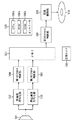
図1は、本実施形態における撮像装置の構成の一例を示すブロック図であり、記録時のデータパスを中心に記載している。
(First embodiment)
Hereinafter, preferred embodiments of the present invention will be described with reference to the drawings.
FIG. 1 is a block diagram illustrating an example of the configuration of the imaging apparatus according to the present embodiment, and mainly describes a data path during recording.
図1において、符号101は、映像を電気信号に変換する撮像手段、符号102は、撮像手段101により得られた電気信号を所望の動画像データに変換する動画像符号化部である。また、符号103は、撮像手段101により得られた電気信号を所望の静止画像データに変換する静止画像符号化部である。符号104及び105は、第1のDMA(Direct Memory Access)制御部、及び第2のDMA制御部である。
In FIG. 1,
静止画符号化部103は、不図示のスイッチにより静止画撮影の指示があると、撮像部101から出力された動画像信号から、1画面の画像データを抽出し、符号化することにより静止画像データを生成する。本実施形態では、動画像データの撮影、記録中においても静止画の撮影を可能である。静止画符号化部103は、動画撮影中に静止画撮影の指示があった場合も、撮像部101からの動画像データ中の1フレームを抽出して静止画像データを生成する。
When there is an instruction to shoot a still image with a switch (not shown), the still image encoding
これらの第1及び第2の第1のDMA制御部104、105は、動画像符号化部102または静止画像符号化部103から生成される動画像データ、静止画像データをメモリ107の所定の連続領域に記録する機能を有している。特に、第1のDMA制御部104は、メモリ107上の2つの連続領域に記録する分割DMA機能を有している。
The first and second first
符号109は、記録媒体(ディスクメディア)110にデータを記録する記録制御部であり、メモリ107上に保持されている動画像データ及び静止画像データを、ディスクメディア110に記録する機能を有している。
ディスクメディア110は、固定サイズの記録ブロック単位に区切られており、この記録ブロック単位でデータの記録及び読み出しが可能となっている。
符号108は周期タイマであり、所定の周期で起動され、第2のDMA制御部105、第3のDMA制御部106の設定値変更、記録制御部109を起動するタイミング等を生成する。
The
Reference numeral 108 denotes a periodic timer, which is activated at a predetermined period, and generates a setting value change of the second
以上の各ブロックは、CPU100aやそのプログラム等が記録されたROM100b、プログラムを実行する際に必要となるRAM100c等により構成されるコントローラ100により制御され、撮像装置として機能する。
Each of the above blocks is controlled by the
また、本実施形態では、符号化後の動画像データのデータレートよりも、ディスクメディア110に対して記録可能なデータレートの方が高いため、所定の記録単位毎で間欠的に動画像データを記録する。具体的には、周期タイマ108に設定された周期毎に、メモリ107に保持されている未記録の撮影データを、記録ブロックサイズの整数倍だけ、一度に記録する。
Further, in this embodiment, since the data rate that can be recorded on the
次に、第1のDMA制御部104、第2のDMA制御部105及び第3のDMA制御部106の撮影時の動作について、図2を参照しながら説明する。
第1のDMA制御部104は、動画像符号化部102により生成される動画像データをメモリ107に転送する機能を有している。したがって、コントローラ100により転送許可状態に設定されると、転送開始、停止の動作については動画像符号化部102により制御される。
Next, operations at the time of shooting by the first
The first
第1のDMA制御部104は、メモリ107上の2つの連続領域に転送可能な分割DMA機能を有している。コントローラ100は、第1のDMA領域開始アドレス(MA1)201、第1のDMA領域サイズ(MS1)202、第2のDMA領域開始アドレス(MA2)203、第2のDMA領域サイズ(MS2)204の設定を行う。
The first
これらのアドレスMA1、MA2はコントローラ100により、メモリ107上のメモリアドレスが設定され、データ転送中は自動的にインクリメントされる。ここで、メモリ107は、アドレスが上限に達した後は再び先頭アドレス(アドレス0)を指定するよう、循環的にアドレスを指定しながらデータを記憶する、リングバッファとして利用される。
These addresses MA1 and MA2 are set to memory addresses on the
前述の領域サイズMS1、MS2についても、コントローラ100により設定され、データ転送中は自動的にデクリメントされる。そして、「0」になった場合には、コントローラ100に対して割り込みが発行され、もう一方のDMA領域サイズの値が「0」以上の場合には、そちらの領域に引き続きデータ転送が行われる。
The area sizes MS1 and MS2 are also set by the
また、もう一方のDMA領域サイズの値が「0」の場合には、データ転送は中断される(異常終了)。前記開始アドレスや領域サイズは、一定周期毎にコントローラ100により設定値が更新されるが、その詳細については後述する。
If the value of the other DMA area size is “0”, the data transfer is interrupted (abnormal termination). The start address and area size are updated by the
第2のDMA制御部105は、静止画像符号化部103により生成される静止画像データをメモリ107に転送する機能を有している。したがって、コントローラ100により転送許可状態に設定されると、静止画符号化部103により静止画像が生成された際にデータ転送が開始される。そして、1枚分の静止画像データ転送が終わると、コントローラ100に対して割り込みが発行される。
The second
コントローラ100は、DMA領域開始アドレス(SA)205、DMA領域サイズ(SS)206の設定を行う。データ転送中のSA205、SS206については、前記MA1、MS1と同様の更新が行なわれる。SS206には1枚の静止画像データを保持するために十分なサイズが設定されるが、転送中にSS206が「0」になった場合には、コントローラ100に割り込みが発行され、転送は中断される(異常終了)。前記開始アドレスや領域サイズは、一定周期毎にコントローラ100により設定値が更新されるが、その詳細については後述する。
The
第3のDMA制御部106は、メモリ107上に保持されている撮影データ(動画像データ、静止画像データ)を記録制御部109に転送する機能を有している。コントローラ100は、DMA領域開始アドレス(DA)207、DMAサイズ(DS)208の設定を行う。
The third
データ転送の開始は、コントローラ100によって指示され、DMAサイズ分の転送が行われる。データ転送中のDA207、DS208については、前記MA1,MS1と同様の更新が行われ、DS208が「0」になった際に、コントローラ100に対して割り込みが発行される。前記開始アドレスやDMAサイズ208は、一定周期毎にコントローラ100により設定値が更新されるが、その詳細については後述する。
The start of data transfer is instructed by the
図3は、本実施形態の撮像装置で、動画像と静止画像の同時撮影した場合の動作について説明する図である。
動画像の撮影が開始されると、動画像符号化部102より、符号301を付して示したように、動画像データが撮影終了まで生成され続ける。生成された動画像データ301は、先に説明したように第1のDMA制御部104により、リングバッファを形成するメモリ107に転送される。ここでは説明の都合上、リングバッファに符号302を付し、アドレスは左から右にインクリメントされる。リングバッファ302は、記録媒体の記録ブロックサイズの整数倍サイズを、物理的に持つものとする。
FIG. 3 is a diagram for explaining the operation when a moving image and a still image are simultaneously captured by the imaging apparatus of the present embodiment.
When shooting of a moving image is started, moving image data continues to be generated from the moving
動画像と同様に、静止画像についても利用者の指示により静止画像が撮影され(符号303〜305)、1枚毎に第2のDMA制御部105により、リングバッファ302に転送される。その際に、転送先がその周期の動画像データの転送先と重ならないように、動画像データの転送先よりもアドレスが進んだ位置に転送される(符号306〜308)。
Similar to a moving image, a still image is also photographed according to a user's instruction (
静止画像の撮影があった次周期の動画像データの転送は、メモリ107上にすでに転送済みの静止画像データ306〜308を上書きしないようにデータ転送する必要がある。このため、符号309、310を付したように、第1のDMA制御部104により、2つの領域に対して分割DMAが行われる。
The transfer of moving image data in the next cycle in which a still image was shot needs to be transferred so as not to overwrite the already transferred still image
このように、リングバッファ302上に保持された撮影データは、動画像データ、静止画像データの区別は無い。そして、固定周期毎に、記録ブロックサイズ単位のサイズで、第3のDMA制御部106により記録制御部109に転送され、ディスクメディア110に記録される。
Thus, the shooting data held on the
以上のようにして、本実施形態の撮像装置においては動画像、静止画像それぞれに専用のバッファを設けること無く、1つのリングバッファ302により動画像、静止画像の同時撮影を実現している。
As described above, in the imaging apparatus according to the present embodiment, simultaneous shooting of moving images and still images is realized by one
次に、同時撮影方式を実現するための第1のDMA制御部104、第2のDMA制御部105及び第3のDMA制御部106の制御方法について説明する。
図4は、動画像開始から終了までのDMA制御処理手順の一例を説明するフローチャートである。
図4に示したように、動画像の撮影が開始されると(ステップS401)、まず初期設定処理(ステップS402)が実行され、割り込み待ち状態(ステップS403)となる。
Next, a control method of the first
FIG. 4 is a flowchart illustrating an example of a DMA control processing procedure from the start to the end of a moving image.
As shown in FIG. 4, when shooting of a moving image is started (step S401), an initial setting process (step S402) is first executed, and an interrupt wait state (step S403) is entered.
ステップS403において割り込みにより処理が再開されると、割り込み要因に応じて、それぞれの割り込み処理が実行される。割り込み要因としては、周期タイマ割り込み(ステップS404)、第1のDMA転送完了割り込み(ステップS405)、第3のDMA転送完了割り込み(ステップS406)がある。また、静止画像転送完了割り込み(ステップS407)、撮影終了割り込み(ステップS408)もある。 When the process is resumed by an interrupt in step S403, each interrupt process is executed according to the interrupt factor. Interrupt factors include a periodic timer interrupt (step S404), a first DMA transfer completion interrupt (step S405), and a third DMA transfer completion interrupt (step S406). There is also a still image transfer completion interrupt (step S407) and a shooting end interrupt (step S408).
それぞれの割り込みに対応して、周期タイマ割り込み処理(ステップS409)、第1のDMA転送完了割り込み処理(ステップS410)、第3のDMA転送完了割り込み処理(ステップS411)、静止画像転送完了割り込み処理(ステップS414)がある。また、撮影終了割り込み時には処理が終了となる。さらに、前記第3のDMA転送完了割り込み処理が異常終了した場合にも、撮影は終了となる。 Corresponding to each interrupt, a periodic timer interrupt process (step S409), a first DMA transfer completion interrupt process (step S410), a third DMA transfer completion interrupt process (step S411), a still image transfer completion interrupt process (step S411) There is step S414). Also, the process ends when the shooting end interrupt occurs. Further, the shooting is ended also when the third DMA transfer completion interrupt process ends abnormally.
図5(a)に、初期設定処理(ステップS402)の詳細を示す。
初期設定処理が開始されると(ステップS501)、記録媒体に間欠記録するため周期を生成する周期タイマの設定が行われ、タイマが起動される(ステップS502)。
FIG. 5A shows details of the initial setting process (step S402).
When the initial setting process is started (step S501), a cycle timer for generating a cycle for intermittent recording on the recording medium is set, and the timer is started (step S502).
続いて、動画像データの転送を担う第1のDMA制御部104に対する初期設定が行われる(ステップS503)。第1のDMA制御部104は、先に述べたように分割DMAが可能となっており、DMA領域として第1及び第2の領域を持つことができる。説明の便宜上、その時点で実際に転送を担っているDMA領域番号についてn(カレントDMA領域番号)と表記し、予約されたDMA領域番号についてはm(予約DMA領域番号)と表記する。
Subsequently, initial setting is performed for the first
つまり、第1のDMA領域に対してデータ転送が行われている場合には、n=1、m=2となり、第2のDMA領域に対してデータ転送が行われている場合にはn=2、m=1となる。初期設定時には、n=1、m=2と設定され、第1のDMA領域がこの時点で有効なデータ転送領域となる。 That is, when data transfer is being performed to the first DMA area, n = 1 and m = 2, and when data transfer is being performed to the second DMA area, n = 2, m = 1. At the initial setting, n = 1 and m = 2 are set, and the first DMA area becomes an effective data transfer area at this time.
この第1のDMA領域の先頭アドレスは、メモリ107上に形成されるリングバッファ302の先頭アドレスとし、MA1(第1のDMA領域開始アドレス)に本アドレスを設定する。さらに、領域1のサイズをMS1(第1のDMA領域サイズ)に設定する。
The start address of the first DMA area is set as the start address of the
この第1の領域サイズは、撮影動画像データのビットレートと、先に設定した周期タイマの周期により算出される。本実施形態においては、1周期の間に生成される動画像データを記録可能なサイズ、かつ2周期分のサイズよりも小さなサイズで、記録媒体の記録ブロックサイズの整数倍となるように設定される。このサイズを以降MSと表記する。 The first area size is calculated based on the bit rate of the captured moving image data and the period of the period timer set in advance. In this embodiment, the moving image data generated during one cycle is set to a size that can be recorded and smaller than the size of two cycles, and an integral multiple of the recording block size of the recording medium. The This size is hereinafter referred to as MS.
MA2、MS2については「0」を設定する。ここで「0」を設定した場合は、第2のDMA領域がリングバッファ上に確保されていないことを意味し、その場合、分割DMAは行われない。このように設定された第1のDMA制御部104は転送可能状態に設定される。
“0” is set for MA2 and MS2. When “0” is set here, it means that the second DMA area is not secured on the ring buffer, and in this case, divided DMA is not performed. The first
次に、静止画像データの転送を担う第2のDMA制御部に対する初期設定が行われる。SA(DMA領域開始アドレス)に、(MA1+MS1)のアドレスを設定する。すなわち、先に説明した第1のDMA領域に隣接して続く形でDMA領域が設定される。 Next, initial setting is performed for the second DMA control unit responsible for transferring still image data. An address of (MA1 + MS1) is set in SA (DMA area start address). That is, the DMA area is set so as to continue adjacent to the first DMA area described above.
また、前記のようにMS1を設定しているため、MA1から記録媒体に記録を行った場合に、SAが記録媒体に記録される位置は、記録ブロックにアライメントされた位置となっている。 Since MS1 is set as described above, when recording is performed from MA1 onto the recording medium, the position where SA is recorded on the recording medium is the position aligned with the recording block.
SS(DMA領域サイズ)には、(MA−SA)を設定する。すなわち、初期設定の状態では、リングバッファは動画像データ転送用の領域と、静止画像データ転送用の領域の2領域で占められることになる。また、1周期前のSAの値を保持するための「SAold」には、初期設定時にはSAを設定する。このように設定された第2のDMA制御部105は転送可能状態に設定される(ステップS504)。
SS (DMA area size) is set to (MA-SA). That is, in the initial setting state, the ring buffer is occupied by two areas, a moving image data transfer area and a still image data transfer area. Also, “SAold” for holding the SA value one cycle before is set at the time of initial setting. The second
記録制御部109への撮影データの転送を担う第3のDMA制御部106については、DMA領域開始アドレスとして、MA1と同じアドレス、すなわちリングバッファの先頭アドレスを設定する(ステップS505)。
For the third
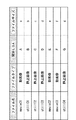
続いて、ファイルテーブル(図6)に対し、これから記録が行われる動画像ファイルの情報として、ファイル名、ファイルタイプ、開始LBAを記録する(ステップS506)。ファイルタイプは、静止画像ファイル/動画像ファイルを区別するためのもので、ここでは動画像ファイルとなる。開始LBA(Logical Block Addressing)は、記録媒体の空き領域の先頭LBAが記録される。このLBA以降のブロックは全て空き領域となっており、動画像データ、静止画像データの記録が可能となっている。以上で初期設定処理は終了する(ステップS507)。 Subsequently, a file name, a file type, and a start LBA are recorded as information of a moving image file to be recorded in the file table (FIG. 6) (step S506). The file type is for distinguishing between still image files / moving image files, and is a moving image file here. The start LBA (Logical Block Addressing) records the head LBA of the free area of the recording medium. All blocks after the LBA are free areas, and moving image data and still image data can be recorded. This completes the initial setting process (step S507).
図5(b)は、静止画像記録可否判定処理の一例を説明するフローチャートである。
ステップS5010で静止画像記録可否判定処理が開始されると、DMA領域サイズ(SS)206は十分なサイズであるか否かの判定がステップS5011において判定される。この判定の結果、十分なサイズである場合にはステップS5012に進み、静止画撮影許可を与えて可否判定処理を終了する(ステップS5014)。
FIG. 5B is a flowchart for explaining an example of a still image recording availability determination process.
When the still image recording availability determination process is started in step S5010, it is determined in step S5011 whether or not the DMA area size (SS) 206 is a sufficient size. If the result of this determination is that the size is sufficient, processing proceeds to step S5012, permission for still image shooting is given, and the permission determination processing is terminated (step S5014).
また、ステップS5011の判定の結果、DMA領域サイズ(SS)206が所定の閾値よりも少なく、十分なサイズではなかった場合にはステップS5013に進み、静止画撮影を禁止する処理を行い、その後、可否判定処理を終了する(ステップS5014)。 If the result of determination in step S5011 is that the DMA area size (SS) 206 is less than the predetermined threshold and is not sufficient, the process proceeds to step S5013, where processing for prohibiting still image shooting is performed. The availability determination process is terminated (step S5014).
図7は、周期タイマ割り込み処理の詳細例を示すフローチャートである。
周期タイマ割り込み処理が開始されると(ステップS701)、始めにリングバッファ302上の撮影データに対する記録制御部109へのデータ転送設定が、第3のDMA制御部106に対して行われる。
FIG. 7 is a flowchart showing a detailed example of the periodic timer interrupt process.
When the periodic timer interrupt process is started (step S701), first, the third
DMA領域開始アドレス(DA)207については、初期設定以降は、データ転送とともに自動的にインクリメントされるため設定不要である。また、DMAサイズ(DS)208については、(MAn−DA)を記録ブロックサイズの整数倍で丸められたサイズが設定される。 The DMA area start address (DA) 207 need not be set since it is automatically incremented with data transfer after the initial setting. For the DMA size (DS) 208, a size obtained by rounding (MAn-DA) by an integer multiple of the recording block size is set.
図8(a)に、周期タイマ割り込み時におけるリングバッファ302の状態の一例を示す。図8において、符号801が、1周期でリングバッファ302に転送された動画像データを示す。この場合、DMA領域開始アドレス(DA)207、第1のDMA領域開始アドレス(MA1)201は、符号802、803にそれぞれ位置している。
FIG. 8A shows an example of the state of the
したがって、DMAサイズ(DS)208は符号804で示される。このように設定された第3のDMA制御部106は、コントローラ100により転送が起動され(ステップS703)、記録制御部109を介して記録媒体に撮影データが記録される。
Accordingly, the DMA size (DS) 208 is indicated by
続いて、静止画記録フラグがチェックされる(ステップS704)。ここでチェックするフラグは、この1周期内に静止画像の撮影が行われたか否かを示すフラグであり、後に詳細を説明する静止画像転送完了割り込み処理(ステップS414)でフラグのセットが行われる。 Subsequently, the still image recording flag is checked (step S704). The flag to be checked here is a flag indicating whether or not a still image has been shot within this one cycle, and the flag is set in a still image transfer completion interrupt process (step S414) described later in detail. .
ステップS704の判定の結果、フラグがセットされている場合には、リングバッファ302上に静止画像データが存在している(図8(b)符号805)。この場合は、次の周期で転送される動画像データは分割DMAで、静止画像データを上書きしないようにリングバッファ302に転送される必要がある。
If the flag is set as a result of the determination in step S704, still image data exists on the ring buffer 302 (
一方、ステップS704の判定の結果、フラグがセットされていない場合には、図8(a)のようなリングバッファ302の状態であり、次の周期で転送される動画像データは分割DMAで転送される必要はない。
On the other hand, if the flag is not set as a result of the determination in step S704, the state is the
以上のことから、第1のDMA制御部104に対しては、以下のような設定が行われる。すなわち、ステップS704のフラグチェックによりフラグセットが確認された場合には、分割DMA設定が行われ(ステップS705)、MSnには(SAold−MAn)が設定される。図8(b)のような状態の場合、SAold、MAn(ここではMA1)は符号805、806で示され、MSn(ここではMS1)は、符号807で示される。
From the above, the following setting is performed for the first
分割DMAの第2の領域については、すでに記録されている静止画像データ領域805を飛び越す形で設定する必要があり、MAmは静止画像データを越えた最初の記録ブロックサイズにアラインされる位置に設定される(符号808のMA2)。
The second area of the divided DMA needs to be set so as to skip the already recorded still
記録ブロックサイズにアラインする理由は、記録媒体に記録された場合に、静止画像データと動画像データとが同一記録ブロック内に混在し、ファイルとして分離することができなくなることを回避するためである。 The reason for aligning to the recording block size is to avoid that when recorded on a recording medium, still image data and moving image data are mixed in the same recording block and cannot be separated as a file. .
MSmには、1周期毎に必要とされる領域サイズMSから、MSnを差し引いた(MS−MSn)を設定する(符号809のMS2)。この時点で、静止画記録フラグをクリアする。 MSm is set to (MS-MSn) obtained by subtracting MSn from the area size MS required for each period (MS2 of reference numeral 809). At this point, the still image recording flag is cleared.
一方、ステップS704のフラグチェックによりフラグセットが確認されなくて、静止画像データの記録が無く、分割DMAの必要がない場合には、MSnにMSを設定し、MAm、MSmには「0」を設定する(ステップS706)。 On the other hand, if the flag set is not confirmed by the flag check in step S704, there is no recording of still image data and there is no need for divided DMA, MS is set to MSn, and "0" is set to MAm and MSm. Setting is made (step S706).
引き続き、第2のDMA制御部105への設定が行われる(ステップS707)。DMA領域開始アドレス(SA)205には、先に設定した第1のDMA制御部104の転送領域に続くアドレスが設定される(記録ブロックサイズにアライン、符号810)。DMA領域開始アドレス(SA)205の値を保持するSAoldについても同じ値を設定する。
Subsequently, the setting to the second
DMA領域サイズ(SS)206には、リングバッファ302の残りの空き領域を設定するため、(DA−SA)が設定される(符号811)。このDMA領域サイズ(SS)206に対し、ステップS708の静止画像記録可否判定が実施される。 In the DMA area size (SS) 206, (DA-SA) is set in order to set the remaining free area of the ring buffer 302 (reference numeral 811). For this DMA area size (SS) 206, the still image recording possibility determination in step S708 is performed.
図5(b)のフローチャートを用いて静止画像像記録可否判定処理を説明したように、DMA領域サイズ(SS)206が十分なサイズが確保されているか否かをもとに、これからの1周期の間に同時静止画撮影を許可するか否かを決定する。DMA領域サイズ(SS)206が小さくなる原因としては、撮像装置の揺れ等の要因により、撮影データの記録媒体への記録が進まず、DAの更新が進まない場合に生じる。いわゆるショックプルーフメモリのオーバフローに相当し、このような場合には、まず同時静止画撮影が禁止されることとなる。これにより、ショックに強い撮像装置を実現できる。また、同一のリングバッファで動画像データと静止画像データのバッファリングを行っているため、静止画像データのライトポインタを無効化するだけで、前記変更を実現できる。以上で周期タイマ割り込み処理が終了する(ステップS709)。 As described with reference to the flowchart of FIG. 5B, the still image image recording availability determination process, one cycle from now on based on whether or not the DMA area size (SS) 206 is sufficiently large. It is determined whether or not simultaneous still image shooting is permitted. The reason why the DMA area size (SS) 206 becomes smaller occurs when recording of shooting data to a recording medium does not proceed and DA update does not proceed due to factors such as shaking of the imaging device. This corresponds to an overflow of the so-called shock proof memory, and in such a case, simultaneous still image shooting is first prohibited. As a result, an imaging device that is resistant to shock can be realized. Further, since the moving image data and the still image data are buffered by the same ring buffer, the change can be realized only by invalidating the write pointer of the still image data. This completes the periodic timer interrupt process (step S709).
図9(a)に、第1のDMA転送完了割り込み処理を示す。
第1のDMA制御部104の転送完了割り込みの発生(ステップS901)は、カレントのDMA転送領域が「0」になったことを示す割り込みであり、予約DMA領域をカレントのDMA領域に切り換える必要がある。
FIG. 9A shows the first DMA transfer completion interrupt process.
The occurrence of the transfer completion interrupt (step S901) of the first
本実施形態においてはn=1、m=2で割り込みが発生した場合には、n=2、m=1に切り替わり、n=2、m=1で割り込みが発生した場合には、n=1、m=2に切り替わる(ステップS902)。 In the present embodiment, when an interrupt occurs when n = 1 and m = 2, the mode is switched to n = 2 and m = 1. When an interrupt occurs when n = 2 and m = 1, n = 1. , M = 2 are switched (step S902).
切り替え後、MSnの値をチェックする(ステップS903)。ステップS903でチェックした結果、この値が「0」であった場合には、これ以上動画像データをリングバッファ302に転送することができなくなるため、異常終了となる(ステップS905)。異常終了の場合には、図4で説明したフローチャートのステップS413に進むことになり、動画像撮影自体も終了する(バッファオーバーフロー)。
After switching, the value of MSn is checked (step S903). As a result of checking in step S903, if this value is “0”, no more moving image data can be transferred to the
一方、ステップS903の判定の結果、MSnが「0」ではない場合には、分割DMAの領域またぎが発生したことによる割り込みであり、引き続き動画像データの転送が行われる(正常終了、ステップS904)。 On the other hand, if the result of determination in step S903 is that MSn is not “0”, this is an interrupt due to the occurrence of a divided DMA area crossing, and moving image data transfer is continued (normal termination, step S904). .
図9(b)に、第3のDMA制御部106の転送完了割り込み処理の一例を示す。
第3のDMA制御部106の転送完了割り込みは、記録制御部109への撮影データの転送完了を示すものである。本割り込みを受けると、次の転送で記録が開始される記録媒体上のLBAの値を更新する(ステップS907)。この値の更新は、リングバッファ302上のアドレスと、そのアドレスのデータが記録媒体上のどのLBAに記録されるかの対応をとるために、常に保持されている。さらに、動画像撮影開始からのトータルの記録媒体への記録サイズを更新する(ステップS908)。その後、処理を終了する(ステップS909)。
FIG. 9B shows an example of the transfer completion interrupt process of the third
The transfer completion interrupt of the third
図9(c)に、静止画像転送完了割り込み処理を示す。
本割り込みは、利用者により静止画像の同時撮影が指示され、1枚分の静止画像データが第2のDMA制御部105によってリングバッファ302に転送が完了したことを示す割り込みである。本割り込みが発生すると(ステップS910)、SAoldの値から、静止画像データが記録媒体上のどのLBAから記録されるかを算出し、ファイルテーブル(図6)に登録する(ステップS911)。
FIG. 9C shows still image transfer completion interrupt processing.
This interrupt is an interrupt indicating that the user has instructed the simultaneous shooting of a still image, and that the still image data for one sheet has been transferred to the
さらに、(SA−SAold)を、静止画像ファイルのファイルサイズとしてファイルテーブルに登録し(ステップS912)、静止画像データが記録された旨を示す静止画記録フラグをセットする(ステップS913)。続いて、さらに静止画像データが撮影された場合に転送されるべき領域のリングバッファ302上のアドレスをDMA領域開始アドレス(SA)205にセットし、領域サイズ(DA−SA)をDMA領域サイズ(SS)206にセットする(ステップS914)。
Further, (SA-SAold) is registered in the file table as the file size of the still image file (step S912), and a still image recording flag indicating that still image data has been recorded is set (step S913). Subsequently, the address on the
静止画像ファイルとしては別ファイルとなるため、このアドレスは記録ブロックサイズにアライメントされたアドレスとなる。同一周期内に複数の静止画像の撮影があった場合は、図8の符号812、813のように、静止画像データがリングバッファ302上に並んで存在することになる。SSに対して、先に述べた静止画像記録可否判定が行われ(ステップS915)、その後で処理を終了する(ステップS916)。
Since the still image file is a separate file, this address is an address aligned with the recording block size. When a plurality of still images are captured within the same period, still image data exists side by side on the
以上、図3から図9を用いて説明した通り、第1のDMA制御部104、第2のDMA制御部105及び第3のDMA制御部106を制御することにより、本実施形態の撮像装置は、動画像と静止画像の同時撮影記録を実現している。
As described above with reference to FIGS. 3 to 9, by controlling the first
以上のように、動画像と静止画像が同時撮影され、図6に示されるようなファイルテーブルが生成された場合、本テーブルからファイルシステムの管理情報を生成する。そして、記録媒体に記録することにより、動画像ファイル、静止画像ファイルとして撮影データを扱うことができるようになる。 As described above, when a moving image and a still image are taken simultaneously and a file table as shown in FIG. 6 is generated, file system management information is generated from this table. Then, by recording on the recording medium, it becomes possible to handle the shooting data as a moving image file and a still image file.
例えば、図6のようなファイルテーブルの情報から、動画像データのサイズ、静止画像データのサイズ、動画像データ/静止画像データの配置情報を生成することが可能であり、図10に示すようなファイル管理情報を生成することができる。そして、このファイル管理情報をディスクメディア110に記録することにより、ディスクメディア110に転送後に動画データと静止画データを独立したファイルとして扱うことが可能となる。
For example, it is possible to generate moving image data size, still image data size, moving image data / still image data arrangement information from the file table information as shown in FIG. 6, as shown in FIG. File management information can be generated. Then, by recording this file management information on the
つまり、動画像データ/静止画像データを一連のリングバッファ302上のデータとして記録することにより、記録処理のオーバーヘッドを削減し、記録終了後は記録データを動画像ファイル/静止画像ファイルとして取り扱えるようにすることができる。
In other words, by recording moving image data / still image data as a series of data on the
以上説明したとおり、本実施形態の撮像装置においては、動画像用バッファ、静止画像用バッファと、それぞれ個別のバッファを設けずに、1つのリングバッファ302を動画像用、静止画像用のバッファとして利用し、同時撮影を実現することができる。
As described above, in the imaging apparatus according to the present embodiment, the moving image buffer and the still image buffer are not provided as separate buffers, and one
また、リングバッファ302の特性上、異常が発生しない限り、同時撮影時の静止画像撮影枚数に制限はない。また、撮影中の撮像装置の揺れ等による記録媒体への書き込み遅延が発生し、リングバッファ302の空き容量が圧迫された場合(少なくなった場合)には、静止画記録可否判定処理を行う。そして、その結果を基にして静止画像撮影を一時的に禁止するポインタ制御手段を設けることにより、動画像データ保持用のバッファを常に確保するようにする。このようにすることにより、動画像撮影ができるだけ中断されないように制御することができる。
Further, due to the characteristics of the
また、動画像データ/静止画像データをそれぞれ別ファイルとして記録するのではなく、記録中は一連のリングバッファ302上のデータとして取り扱うことで記録媒体への記録処理のオーバーヘッドを削減する。そして、記録後にファイル管理情報を生成・記録することにより、最終的には動画像ファイル/静止画像ファイルとして取り扱えるようにすることができる。
In addition, moving image data / still image data is not recorded as separate files, but is handled as data on a series of
(本発明に係る他の実施形態)
前述した本発明の実施形態における撮像装置を構成する各手段、並びに撮像装置の制御方法の各ステップは、コンピュータのRAMやROMなどに記憶されたプログラムが動作することによって実現できる。このプログラム及び前記プログラムを記録したコンピュータ読み取り可能な記録媒体は本発明に含まれる。
(Other embodiments according to the present invention)
Each unit constituting the imaging apparatus and each step of the imaging apparatus control method in the embodiment of the present invention described above can be realized by operating a program stored in a RAM or ROM of a computer. This program and a computer-readable recording medium recording the program are included in the present invention.
また、本発明は、例えば、システム、装置、方法、プログラムもしくは記憶媒体等としての実施形態も可能であり、具体的には、複数の機器から構成されるシステムに適用してもよいし、また、一つの機器からなる装置に適用してもよい。 In addition, the present invention can be implemented as, for example, a system, apparatus, method, program, storage medium, or the like. Specifically, the present invention may be applied to a system including a plurality of devices. The present invention may be applied to an apparatus composed of a single device.
なお、本発明は、前述した実施形態の機能を実現するソフトウェアのプログラム(実施形態では図4、図5、図7、図9に示すフローチャートに対応したプログラム)を、システムあるいは装置に直接、あるいは遠隔から供給する。そして、そのシステムあるいは装置のコンピュータが前記供給されたプログラムコードを読み出して実行することによっても達成される場合を含む。 In the present invention, a software program (in the embodiment, a program corresponding to the flowcharts shown in FIGS. 4, 5, 7, and 9) that realizes the functions of the above-described embodiments is directly or directly stored in a system or apparatus. Supply remotely. In addition, this includes a case where the system or the computer of the apparatus is also achieved by reading and executing the supplied program code.
したがって、本発明の機能処理をコンピュータで実現するために、前記コンピュータにインストールされるプログラムコード自体も本発明を実現するものである。つまり、本発明は、本発明の機能処理を実現するためのコンピュータプログラム自体も含まれる。 Accordingly, since the functions of the present invention are implemented by computer, the program code installed in the computer also implements the present invention. In other words, the present invention includes a computer program itself for realizing the functional processing of the present invention.
その場合、プログラムの機能を有していれば、オブジェクトコード、インタプリタにより実行されるプログラム、OSに供給するスクリプトデータ等の形態であってもよい。 In that case, as long as it has the function of a program, it may be in the form of object code, a program executed by an interpreter, script data supplied to the OS, and the like.
プログラムを供給するための記録媒体としては、例えば、フロッピー(登録商標)ディスク、ハードディスク、光ディスク、光磁気ディスク、MO、CD−ROM、CD−R、CD−RWなどがある。また、磁気テープ、不揮発性のメモリカード、ROM、DVD(DVD−ROM,DVD−R)などもある。 Examples of the recording medium for supplying the program include a floppy (registered trademark) disk, hard disk, optical disk, magneto-optical disk, MO, CD-ROM, CD-R, and CD-RW. In addition, there are magnetic tape, nonvolatile memory card, ROM, DVD (DVD-ROM, DVD-R), and the like.
その他、プログラムの供給方法としては、クライアントコンピュータのブラウザを用いてインターネットのホームページに接続する。そして、前記ホームページから本発明のコンピュータプログラムそのもの、もしくは圧縮され自動インストール機能を含むファイルをハードディスク等の記録媒体にダウンロードすることによっても供給できる。 As another program supply method, a browser on a client computer is used to connect to an Internet home page. The computer program itself of the present invention or a compressed file including an automatic installation function can be downloaded from the homepage by downloading it to a recording medium such as a hard disk.
また、本発明のプログラムを構成するプログラムコードを複数のファイルに分割し、それぞれのファイルを異なるホームページからダウンロードすることによっても実現可能である。つまり、本発明の機能処理をコンピュータで実現するためのプログラムファイルを複数のユーザに対してダウンロードさせるWWWサーバも、本発明に含まれるものである。 It can also be realized by dividing the program code constituting the program of the present invention into a plurality of files and downloading each file from a different homepage. That is, a WWW server that allows a plurality of users to download a program file for realizing the functional processing of the present invention on a computer is also included in the present invention.
また、本発明のプログラムを暗号化してCD−ROM等の記憶媒体に格納してユーザに配布し、所定の条件をクリアしたユーザに対し、インターネットを介してホームページから暗号化を解く鍵情報をダウンロードさせる。そして、ダウンロードした鍵情報を使用することにより暗号化されたプログラムを実行してコンピュータにインストールさせて実現することも可能である。 In addition, the program of the present invention is encrypted, stored in a storage medium such as a CD-ROM, distributed to users, and key information for decryption is downloaded from a homepage via the Internet to users who have cleared predetermined conditions. Let It is also possible to execute the encrypted program by using the downloaded key information and install the program on a computer.
また、コンピュータが、読み出したプログラムを実行することによって、前述した実施形態の機能が実現される。その他、そのプログラムの指示に基づき、コンピュータ上で稼動しているOSなどが、実際の処理の一部または全部を行い、その処理によっても前述した実施形態の機能が実現され得る。 Further, the functions of the above-described embodiments are realized by the computer executing the read program. In addition, based on the instructions of the program, an OS or the like running on the computer performs part or all of the actual processing, and the functions of the above-described embodiments can also be realized by the processing.
さらに、記録媒体から読み出されたプログラムが、コンピュータに挿入された機能拡張ボードやコンピュータに接続された機能拡張ユニットに備わるメモリに書き込まれる。その後、そのプログラムの指示に基づき、その機能拡張ボードや機能拡張ユニットに備わるCPUなどが実際の処理の一部または全部を行い、その処理によっても前述した実施形態の機能が実現される。 Further, the program read from the recording medium is written in a memory provided in a function expansion board inserted into the computer or a function expansion unit connected to the computer. Thereafter, the CPU of the function expansion board or function expansion unit performs part or all of the actual processing based on the instructions of the program, and the functions of the above-described embodiments are realized by the processing.
100 コントローラ
100a CPU
100b ROM
100c RAM
101 撮像手段
102 動画像符合化部
103 静止画像符合化部
104 第1のDMA制御部
105 第2のDMA制御部
106 第3のDMA制御部
107 メモリ
108 周期タイマ
109 記録制御部
100 コントローラ
100a CPU
100b ROM
100c RAM
110 記録媒体(ディスクメディア)
302 リングバッファ
303、304、305 静止画像撮影タイミング
306、307、308 静止画像データ
309、310 分割DMA
100
100b ROM
100c RAM
DESCRIPTION OF
100b ROM
100c RAM
110 Recording media (disc media)
302
Claims (8)
前記撮像手段の出力を用いて動画像データを生成する動画処理手段と、
前記撮像手段の出力を用いて静止画像データを生成する静止画処理手段と、
前記動画像データと前記静止画像データとを記憶するメモリと、
前記メモリにおいて前記静止画像データの記憶領域を予め設定し、前記動画像データの撮影中に生成された前記静止画像データを前記静止画像データの記憶領域に記憶すると共に、前記動画像データを前記静止画像データの記憶領域以外の領域に記憶するよう前記メモリに対する前記動画像データと静止画像データの記憶動作を制御するメモリ制御手段と、
前記メモリに記憶された動画像データと静止画像データとを読み出して記録媒体に記録する記録手段とを備え、
前記メモリ制御手段は、前記動画像データを前記静止画像データの記憶領域の前後のアドレスに対して連続して記憶することを特徴とする撮像装置。 Imaging means;
Moving image processing means for generating moving image data using the output of the imaging means;
Still image processing means for generating still image data using the output of the imaging means;
A memory for storing the moving image data and the still image data;
A storage area for the still image data is preset in the memory, the still image data generated during shooting of the moving image data is stored in the storage area for the still image data, and the moving image data is stored in the still image data. Memory control means for controlling the storage operation of the moving image data and still image data for the memory so as to store in an area other than the storage area of the image data;
Recording means for reading out moving image data and still image data stored in the memory and recording them on a recording medium ;
Said memory control unit, an imaging apparatus characterized that you store successively the address before and after the storage area of the still image data to the moving image data.
メモリと、
前記メモリに対する、撮影された前記動画像データと前記静止画像データの記憶動作を制御するメモリ制御手段と、
前記メモリに記憶された動画像データと静止画像データとを読み出して記録媒体に記録する記録手段とを備え、
前記メモリ制御手段は、前記動画像データの撮影中における静止画撮影指示に応じて撮影された静止画像データを前記メモリの指定された記憶領域に記憶すると共に、前記動画像データを前記静止画像データの記憶領域の前後のアドレスに対して連続して記憶することを特徴とする撮像装置。 An apparatus for capturing moving image data and still image data,
Memory,
Memory control means for controlling the storage operation of the captured moving image data and still image data for the memory;
Recording means for reading out moving image data and still image data stored in the memory and recording them on a recording medium;
The memory control means stores still image data shot in response to a still image shooting instruction during shooting of the moving image data in a designated storage area of the memory, and stores the moving image data in the still image data. An image pickup apparatus that stores the addresses continuously before and after the storage area .
前記撮像手段の出力を用いて静止画像データを生成する静止画処理工程と、
前記動画像データと前記静止画像データとを記憶するメモリに前記静止画像データの記憶領域を予め設定し、前記動画像データの撮影中に生成された前記静止画像データを前記静止画像データの記憶領域に記憶すると共に、前記動画像データを前記静止画像データの記憶領域以外の領域に記憶するよう前記メモリに対する前記動画像データと静止画像データの記憶動作を制御するメモリ制御工程と、
前記メモリに記憶された動画像データと静止画像データとを読み出して記録媒体に記録する記録工程とを備え、
前記メモリ制御工程は、前記動画像データを前記静止画像データの記憶領域の前後のアドレスに対して連続して記憶することを特徴とする撮像装置の制御方法。 A moving image processing step for generating moving image data using the output of the imaging means;
A still image processing step of generating still image data using the output of the imaging means ;
A storage area for the still image data is preset in a memory for storing the moving image data and the still image data, and the still image data generated during shooting of the moving image data is stored in the storage area for the still image data. A memory control step for controlling the storage operation of the moving image data and still image data for the memory so as to store the moving image data in an area other than the storage area of the still image data;
A recording step of reading out the moving image data and still image data stored in the memory and recording them on a recording medium ,
The method of controlling an imaging apparatus, wherein the memory control step stores the moving image data continuously with respect to addresses before and after a storage area of the still image data .
Priority Applications (1)
| Application Number | Priority Date | Filing Date | Title |
|---|---|---|---|
| JP2006244690A JP4764296B2 (en) | 2006-09-08 | 2006-09-08 | IMAGING DEVICE AND IMAGING DEVICE CONTROL METHOD |
Applications Claiming Priority (1)
| Application Number | Priority Date | Filing Date | Title |
|---|---|---|---|
| JP2006244690A JP4764296B2 (en) | 2006-09-08 | 2006-09-08 | IMAGING DEVICE AND IMAGING DEVICE CONTROL METHOD |
Publications (3)
| Publication Number | Publication Date |
|---|---|
| JP2008067220A JP2008067220A (en) | 2008-03-21 |
| JP2008067220A5 JP2008067220A5 (en) | 2009-10-22 |
| JP4764296B2 true JP4764296B2 (en) | 2011-08-31 |
Family
ID=39289491
Family Applications (1)
| Application Number | Title | Priority Date | Filing Date |
|---|---|---|---|
| JP2006244690A Expired - Fee Related JP4764296B2 (en) | 2006-09-08 | 2006-09-08 | IMAGING DEVICE AND IMAGING DEVICE CONTROL METHOD |
Country Status (1)
| Country | Link |
|---|---|
| JP (1) | JP4764296B2 (en) |
Families Citing this family (1)
| Publication number | Priority date | Publication date | Assignee | Title |
|---|---|---|---|---|
| JP5820973B2 (en) * | 2010-12-28 | 2015-11-24 | パナソニックIpマネジメント株式会社 | Data recording device |
Family Cites Families (1)
| Publication number | Priority date | Publication date | Assignee | Title |
|---|---|---|---|---|
| JP2001218165A (en) * | 2000-02-04 | 2001-08-10 | Canon Inc | Device and method for recording digital signal, and recording medium |
-
2006
- 2006-09-08 JP JP2006244690A patent/JP4764296B2/en not_active Expired - Fee Related
Also Published As
| Publication number | Publication date |
|---|---|
| JP2008067220A (en) | 2008-03-21 |
Similar Documents
| Publication | Publication Date | Title |
|---|---|---|
| JP2004038515A (en) | Data recording device | |
| CN107423095B (en) | Data processing method and device adaptive to hardware, storage medium and computer equipment | |
| JP4764296B2 (en) | IMAGING DEVICE AND IMAGING DEVICE CONTROL METHOD | |
| JP2004266386A (en) | Recorder | |
| JP6220160B2 (en) | Reproducing apparatus and control method thereof | |
| JP2007193531A (en) | Image data recording method and image data recording device | |
| JP5814739B2 (en) | Recording device | |
| JP2006197561A (en) | Data recording method and device | |
| JP2006323462A (en) | File-copying device and file-copying method | |
| JP4534940B2 (en) | Information recording apparatus, imaging apparatus, information recording control method, and computer program | |
| US9124859B2 (en) | Image processing apparatus and image processing method | |
| JP4817634B2 (en) | Data storage | |
| JP2002300520A (en) | File recording system, file processing system, image display device and image editing device | |
| JP3620241B2 (en) | File management apparatus, file management method, recording medium, and file management system | |
| JP2007081842A (en) | Image managing device | |
| JP3552247B2 (en) | Electronic still camera | |
| JP2007134910A (en) | Imaging apparatus, memorandum information adding method, memorandum information candidate list generating method, program, and computer-readable recording medium | |
| JP2009217588A (en) | Filing system, electronic camera, file access method, and program | |
| JP2006048227A (en) | Memory device, memory device control method and data processing system | |
| JP4003709B2 (en) | File management apparatus, file management method, and file management system | |
| JP6552318B2 (en) | INFORMATION PROCESSING APPARATUS AND ITS CONTROL METHOD AND PROGRAM | |
| US20060155767A1 (en) | Information recording-and-reproducing method and information recording-and-reproducing apparatus with play-list copy function | |
| JP2001128166A (en) | Integrated circuit for image compression and image compressing device | |
| JP4373259B2 (en) | Data recording / reproducing device | |
| JP2001298702A (en) | File management system for digital camera and storage device |
Legal Events
| Date | Code | Title | Description |
|---|---|---|---|
| A521 | Request for written amendment filed |
Free format text: JAPANESE INTERMEDIATE CODE: A523 Effective date: 20090907 |
|
| A621 | Written request for application examination |
Free format text: JAPANESE INTERMEDIATE CODE: A621 Effective date: 20090907 |
|
| A977 | Report on retrieval |
Free format text: JAPANESE INTERMEDIATE CODE: A971007 Effective date: 20110209 |
|
| A131 | Notification of reasons for refusal |
Free format text: JAPANESE INTERMEDIATE CODE: A131 Effective date: 20110322 |
|
| A521 | Request for written amendment filed |
Free format text: JAPANESE INTERMEDIATE CODE: A523 Effective date: 20110517 |
|
| TRDD | Decision of grant or rejection written | ||
| A01 | Written decision to grant a patent or to grant a registration (utility model) |
Free format text: JAPANESE INTERMEDIATE CODE: A01 Effective date: 20110607 |
|
| A01 | Written decision to grant a patent or to grant a registration (utility model) |
Free format text: JAPANESE INTERMEDIATE CODE: A01 |
|
| A61 | First payment of annual fees (during grant procedure) |
Free format text: JAPANESE INTERMEDIATE CODE: A61 Effective date: 20110610 |
|
| FPAY | Renewal fee payment (event date is renewal date of database) |
Free format text: PAYMENT UNTIL: 20140617 Year of fee payment: 3 |
|
| R150 | Certificate of patent or registration of utility model |
Free format text: JAPANESE INTERMEDIATE CODE: R150 |
|
| LAPS | Cancellation because of no payment of annual fees |