JP4756609B2 - Rotary cutting tool - Google Patents
Rotary cutting tool Download PDFInfo
- Publication number
- JP4756609B2 JP4756609B2 JP2008082579A JP2008082579A JP4756609B2 JP 4756609 B2 JP4756609 B2 JP 4756609B2 JP 2008082579 A JP2008082579 A JP 2008082579A JP 2008082579 A JP2008082579 A JP 2008082579A JP 4756609 B2 JP4756609 B2 JP 4756609B2
- Authority
- JP
- Japan
- Prior art keywords
- tip
- chips
- chip
- rake face
- cutting tool
- Prior art date
- Legal status (The legal status is an assumption and is not a legal conclusion. Google has not performed a legal analysis and makes no representation as to the accuracy of the status listed.)
- Expired - Fee Related
Links
Images


Description
本発明は、各種材料に形成された穴の加工を行う回転切削工具に関するもので、特にアルミニウム合金などの非鉄金属材料に形成された止まり穴の仕上げ加工を行うための回転切削工具に関する。 The present invention relates to a rotary cutting tool for machining holes formed in various materials, and more particularly to a rotary cutting tool for finishing a blind hole formed in a non-ferrous metal material such as an aluminum alloy.
自動車の基幹部品の一つであるバルブボディは、アルミダイカストなどの材料が使用されているが、部品の集約化に伴いその構造が複雑化しており、油圧制御用の穴が多段形状になったり多数の総形形状の穴で構成されるようになっている。このような穴の仕上げ加工を行うために、例えば切れ刃にダイヤモンド焼結体を用いたリーマなどが用いられる。このリーマで加工を行う際に、加工形態によっては切屑がリーマに巻き付くことがあり、作業能率を低下させたり加工面に傷が入るなどの問題が生じやすくなる。特に、加工部分の形状が貫通穴ではなく止まり穴である場合は切屑の排出性が悪くなり、切れ刃に切屑が巻き付いたり、加工後に穴の中に切屑が残り、次工程で切屑の処理が必要になって生産能率の低下をきたすなどの問題が生じる。従来、切削工具で切れ刃に切屑が巻き付くのを防止する対策として、切れ刃チップに切屑のブレーク機能を持たせて切屑を分断させる方法があり、その代表的な形状としてチップのすくい面上に段差を設けることで切屑を分断させるようなことが行われる。 The valve body, which is one of the key parts of automobiles, is made of materials such as aluminum die-casting, but the structure has become more complex as the parts are consolidated, and the holes for hydraulic control have become multi-stage shapes. It is made up of a number of holes with a general shape. In order to perform such hole finishing, for example, a reamer using a diamond sintered body for a cutting edge is used. When processing with this reamer, chips may be wound around the reamer depending on the processing form, and problems such as reduced work efficiency and scratches on the processed surface are likely to occur. In particular, if the shape of the machined part is not a through hole but a blind hole, the chip discharge performance will deteriorate, and the chip will wrap around the cutting edge, or the chip will remain in the hole after machining, and the chip will be processed in the next process. Problems such as the need to reduce production efficiency arise. Conventionally, as a measure to prevent chips from being wrapped around the cutting edge with a cutting tool, there has been a method of cutting the chip by giving the chip a break function, and the typical shape is on the rake face of the chip. The chip is divided by providing a step in the chip.
ブレーク機能を持たせるためにすくい面上に段差を設けた切削工具の例として、特許文献1から4に記載の工具がある。特許文献1に記載の工具は図5に示すように、切れ刃が形成された高硬度焼結体22をシャンク21にロウ付けしたバイトで、高硬度焼結体22のすくい面23に連なるシャンク21のすくい面に切屑処理用の突起29を設けたものである。この工具は、高硬度焼結体22が設けられたバイトであっても簡単な構造で切屑処理性を高めることができ、切削時における切屑の向き、長さおよび形状を容易にコントロールできるものとされている。また、特許文献2に記載の工具は図6に示すように、ダイヤモンドやCBNの超硬質焼結体32を有する切削工具で、すくい面33上に複雑な三次元形状のチップブレーカー39を設けたものであり、複雑な三次元形状のチップブレーカー39を設けることで切屑処理性に優れたものとすることができるものとされている。さらに、特許文献3に記載の工具は図7に示すように、切れ刃から延びる第1すくい面43aと、第1すくい面43aの後方に設けられ第1すくい面43aよりも高さ位置が高い第2すくい面43bと、第1すくい面43aの後縁と第2すくい面43bの前縁とを接続する壁面50を設けるとともに、切れ刃に切欠部45を設け、壁面50が切れ刃と平行に延びている構造としたものである。この構造によれば、切屑の長さ方向が分断されるだけでなく、切欠部45により切屑の幅方向も小さく分断されるため、より小さな切屑とすることができ排出性を向上させることができるものである。また、切屑の幅方向を分断できる切削工具として、特許文献4に記載の工具がある。この工具は、溝入れバイトのすくい面53上に分断切れ刃58と分断用逃げ面60a、60bを設け、分断切れ刃58の稜から後方に向かって裾広がりの山形を形成する逃げ部59を設けることで、切屑を幅方向に分断させ、分断後の切屑を溝の外部に排出させ、切屑が溝内で挟まることがないようにしたものである。
しかしながら、特許文献1に記載の構造の切屑処理用の突起や特許文献2に記載の構造のチップブレーカーを、止まり穴を加工するリーマのような回転切削工具に設けた場合には様々な問題が発生する。このような回転切削工具の場合、切れ刃は外周の軸方向に外周切れ刃が設けられるとともに工具先端の半径方向に先端切れ刃が設けられ、この工具で加工した場合には、先端切れ刃も切屑を発生させる。そして、先端切れ刃は加工の際に同時に作用する部分が長いため、発生する切屑の幅は広くなる。特許文献1や2に記載のような構造のブレーカをすくい面上に設けた場合、先端切れ刃から発生した切屑は長さ方向には分断されて短くなるが、前述のように切屑の幅が大きいため、長さ方向に分断されても切屑は依然として大きく、切れ刃に巻き付くことは防止できても排出性は良くならない。しかも止まり穴を加工する場合、穴の中に切屑が溜まりやすいこともあってより排出性は悪く、加工面の面あらさが粗くなったり刃先が欠けたりするトラブルも発生しやすいという問題がある。
However, there are various problems when the chip processing protrusion having the structure described in
特許文献3に記載の工具は、切屑を小さく分断して排出性を向上させることができ、上記のような問題を解決できるものであるが、切れ刃に切欠部を設けるために、この切れ刃で加工した面のうち切欠部の部分には削り残しが発生したり、加工した面の精度が悪くなる恐れがある。また、切欠部付近の切れ刃が欠けやすくなり、寿命が短くなる問題が生じる。さらに、切れ刃が摩耗し再研磨を行って切れ刃を再生する場合に、切欠部があるとこれを一旦除去する必要があるため、再研磨を行える回数が減り、この点でも工具としての寿命が短くなる。
The tool described in
さらに、特許文献4に記載の工具は、切屑の幅方向を分断できるものであるが、切屑がすくい面上を流れてカールしながら分断切れ刃に接する際には、分断切れ刃上を滑る形になり、切屑を確実に分断できない恐れがあるため、切屑が分断用逃げ面の方へ逸れて行くことが考えられる。また、切屑の流れる方向が逸れずに分断切れ刃上を流れたとしても、分断切れ刃上でもカールするため、切屑を幅方向に確実に分断できない恐れがある。
Furthermore, although the tool described in
このようなことから、本発明は特に止まり穴のような切屑の排出されにくい穴を加工する回転切削工具において、切屑を長さ方向および幅方向に確実に分断して小さくすることで、効率よく排出させることができ、加工面の精度や刃先の状態を悪化させにくく、切れ刃の再研磨も容易で寿命も長くすることができる回転切削工具を提案するものである。 For this reason, in the rotary cutting tool for machining a hole such as a blind hole in which chips are difficult to be discharged, the chip is efficiently divided by dividing the chips in the length direction and the width direction. The present invention proposes a rotary cutting tool that can be discharged, is difficult to deteriorate the accuracy of the machining surface and the state of the cutting edge, can be easily re-polished, and can have a long life.
本発明者は、ブレーカの形状に工夫を取り入れることで、切れ刃の強度を維持しながらも切屑を幅方向に確実に分断させることができ、切屑を小さくして排出性を向上させることが可能なブレーカ形状を見出した。 The present inventor can divide chips reliably in the width direction while maintaining the strength of the cutting edge by incorporating a device in the shape of the breaker, and can improve the discharge performance by reducing the chips. Found a breaker shape.
本発明の回転切削工具の特徴は、軸状の基材の先端にチップが設けられ、前記チップの先端側には前記基材の半径方向に先端切れ刃が設けられるとともに前記チップの外周側には外周切れ刃が設けられた回転切削工具であって、前記チップのすくい面上にはブレーカ片が設けられ、前記ブレーカ片を構成する面のうち、前記チップの先端側に向きかつ回転軸と交差する方向には起立面が形成されるとともに、前記起立面には前記チップの先端側に突出する凸部が形成され、前記凸部は、前記すくい面に垂直かつ前記先端切れ刃に平行な方向の断面形状が略V字形で、前記略V字形の先端がすくい面側となるように、かつ前記すくい面とは間隔を設けて形成されたことである。 A feature of the rotary cutting tool of the present invention is that a tip is provided at the tip of a shaft-like base material, a tip cutting edge is provided in a radial direction of the base material on the tip side of the tip, and on the outer peripheral side of the tip. Is a rotary cutting tool provided with an outer peripheral cutting edge, and a breaker piece is provided on the rake face of the chip, and of the surfaces constituting the breaker piece, facing the tip end side of the chip and a rotating shaft A rising surface is formed in the intersecting direction, and a convex portion protruding toward the tip side of the chip is formed on the rising surface, and the convex portion is perpendicular to the rake face and parallel to the tip cutting edge. The cross-sectional shape in the direction is substantially V-shaped, and the tip of the substantially V-shape is formed on the rake face side, and the rake face is formed with an interval.
このように、ブレーカ片を構成する面のうち、チップの先端側に向きかつ回転軸と交差する方向の起立面、すなわち先端切れ刃で発生した切屑がチップのすくい面上を流れさらにその切屑が流れてブレーカ片と接する面が形成されているので、すくい面上を流れた切屑がカールしながら起立面に接触して流れる方向が定められる。そして、起立面にはチップの先端側に向かって突出する凸部が形成され、この凸部の形状はすくい面に垂直かつ先端切れ刃に平行な方向(言い換えると、回転切削工具の軸に垂直な方向)の断面形状が略V字形で、略V字形の先端がすくい面側になってすくい面に向くように形成され、すくい面とは間隔を設けて形成されるので、起立面により流れる方向が定められた切屑が、略V字形の先端部により幅方向に分断され、しかも分断された切屑がV字形を形成する面とブレーカ片に接して流れていく。そのため、切屑に強制的にカールさせる力が働いて長さ方向にも分断され、切屑が小さく分断される。従って、止まり穴のような切屑が排出されにくい穴の加工でも切屑を確実に細かく分断し、効率よく排出させることができる。 As described above, among the surfaces constituting the breaker piece, the rising surface in the direction facing the tip end side of the chip and intersecting the rotation axis, that is, the chips generated by the tip cutting edge flow on the rake face of the chip, and the chips are further removed. Since the surface that flows and contacts the breaker piece is formed, the direction in which the chips flowing on the rake face come into contact with the standing surface while curling is determined. The raised surface is formed with a convex portion protruding toward the tip end side of the chip, and the shape of the convex portion is perpendicular to the rake face and parallel to the tip cutting edge (in other words, perpendicular to the axis of the rotary cutting tool). The cross-sectional shape of the first direction is approximately V-shaped, and the tip of the approximately V-shape is formed to face the rake face and face the rake face. The chip whose direction is determined is divided in the width direction by the substantially V-shaped tip, and the divided chip flows in contact with the surface forming the V-shape and the breaker piece. For this reason, a force for forcibly curling the chips works to divide the chips in the length direction, and the chips are divided into small pieces. Therefore, even when processing a hole such as a blind hole in which chips are difficult to be discharged, the chips can be surely divided finely and discharged efficiently.
前記略V字形の先端の角度は、3〜20°とするのが好ましい。3°以上とするのは、略V字形の凸部の強度を保つのに必要なためであり、20°以下とするのは切屑がV字形の先端で分断されながら後端側へ流れていく際の抵抗が過大にならないようにするためである。なお、このような効果をさらに大きくするために、8〜10°とすることがより好ましい。 The angle of the substantially V-shaped tip is preferably 3 to 20 °. The angle of 3 ° or more is necessary for maintaining the strength of the substantially V-shaped convex portion, and the angle of 20 ° or less flows toward the rear end side while the chips are divided at the V-shaped tip. This is to prevent excessive resistance. In order to further increase such an effect, the angle is more preferably 8 to 10 °.
前記略V字形の先端からすくい面までの距離は、1.0〜4.0mmとするのが好ましい。1.0mm以上とするのは、先端切れ刃で生じた切屑がすくい面上を流れて起立面に接触し、その後V字形先端部にスムーズに作用させるのに必要なためであり、4.0mm以下とするのは、切屑がすくい面上を流れて起立面に接触した後、切屑がカールしながらもV字形先端部にスムーズに作用するために必要なためである。なお、このような効果をさらに大きくするために、1.0〜2.0mmとすることがより好ましい。 The distance from the substantially V-shaped tip to the rake face is preferably 1.0 to 4.0 mm. The reason why the thickness is 1.0 mm or more is that it is necessary for the chips generated by the tip cutting edge to flow on the rake face and come into contact with the standing surface, and then to act smoothly on the V-shaped tip, and is 4.0 mm. The reason for the following is that, after the chips flow on the rake face and come into contact with the standing surface, the chips are necessary to smoothly act on the V-shaped tip while curling. In addition, in order to enlarge such an effect further, it is more preferable to set it as 1.0-2.0 mm.
前記起立面の傾斜角βは、15〜45°とするのが好ましい。なお、傾斜角βは、ブレーカ片の底面すなわちチップのすくい面に垂直な方向と起立面とがなす角を言う。傾斜角βを15°以上とするのは、すくい面上を流れてきた切屑がブレーカ片の起立面に接触しV字形先端部にスムーズに流れるようにするのに必要なためであり、45°以下とするのは、すくい面上を流れてきた切屑が起立面に接触しカールしながら流れてもV字形先端部に確実に食い付くようにするのに必要なためである。 The inclination angle β of the rising surface is preferably 15 to 45 °. Note that the inclination angle β refers to an angle formed by a direction perpendicular to the bottom surface of the breaker piece, that is, the chip rake surface, and the standing surface. The reason why the inclination angle β is set to 15 ° or more is that it is necessary for the chips flowing on the rake face to come into contact with the rising surface of the breaker piece and to flow smoothly to the V-shaped tip, 45 ° The reason for the following is that the chips flowing on the rake face are necessary to surely bite the V-shaped tip even if the chips flow while contacting the rising surface and curling.
以上のような回転切削工具は、リーマに適用すると大きな効果が得られる。 When the rotary cutting tool as described above is applied to a reamer, a great effect can be obtained.
回転切削工具の切れ刃で幅の広い切屑が発生する加工においても、切屑を幅方向に確実かつ容易に分断させることが可能になり、凸部を設ける位置により分断した切屑の幅方向の大きさも制御できるため、止まり穴のような切屑の排出されにくい穴を加工する場合においても切屑を小さくして効率よく排出させることが可能になる。これにより、加工面の精度を向上させ、切れ刃の損傷を防止することができ、切れ刃の再研磨も容易で寿命も長くすることができる。 Even in processing that generates wide chips with the cutting edge of a rotary cutting tool, it becomes possible to divide the chips reliably and easily in the width direction, and the width direction size of the chips divided by the position where the convex part is provided Since it can be controlled, even when a hole such as a blind hole in which chips are difficult to be discharged is processed, the chips can be made small and efficiently discharged. Thereby, the precision of a processing surface can be improved, damage to a cutting edge can be prevented, re-polishing of a cutting edge is also easy, and lifetime can be lengthened.
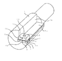
本発明の回転切削工具として、ダイヤモンド焼結体からなるチップを有するダイヤモンドリーマを例にあげて説明する。図1、図2は本発明のリーマの概略を示す図であり、図1は斜視図、図2(a)は正面図、(b)は平面図である。また、図3はチップ上に設けられるブレーカ片を示した図で、いずれも(a)は平面図、(b)は側面図である。 As a rotary cutting tool of the present invention, a diamond reamer having a chip made of a diamond sintered body will be described as an example. 1 and 2 are diagrams showing an outline of the reamer of the present invention. FIG. 1 is a perspective view, FIG. 2 (a) is a front view, and FIG. 2 (b) is a plan view. Moreover, FIG. 3 is a figure which showed the breaker piece provided on a chip | tip, All are (a) a top view, (b) is a side view.
図1および図2を参照して、本発明のリーマは、軸状の本体1の先端側にヌスミ部底面1aとヌスミ部側面1bが設けられることによりヌスミ部が形成され、ヌスミ部の先端部にダイヤモンド焼結体からなるチップ2がろう付けなどにより接合されている。なお、チップ2が接合される部分はヌスミ部底面1aよりさらに掘り込まれてチップの厚み分だけ凹んでおり、チップ2のすくい面3とヌスミ部底面1aとは同一平面上にある。チップ2のうち、先端側にあるすくい面3と先端逃げ面4bとの境界部には先端切れ刃5が形成されており、すくい面3と外周逃げ面4aとの境界部には外周切れ刃6が形成されている。また、外周逃げ面4aと先端逃げ面4bとの境界部には面取り面7が形成され、すくい面3と面取り面7との境界部には斜め切れ刃8が形成されている。
Referring to FIGS. 1 and 2, the reamer of the present invention is provided with a bottom surface 1a and a side surface 1b of the nuisance portion on the distal end side of the shaft-shaped
チップ2のすくい面3上と本体1のヌスミ部底面1a上には両者に跨るようにブレーカ片9が設けられており、ブレーカ片9は取付孔11を介してヌスミ部底面1aあるいはチップ2にネジなどで固定される。ブレーカ片9を構成する面のうち、チップ2の先端側に向き、かつ回転軸と交差する方向には起立面10が形成され、この起立面10には凸部12が設けられている。
A breaker piece 9 is provided on the
図3を参照して、ブレーカ片9に設けられた凸部12は、すくい面3に垂直かつ先端切れ刃5に平行な方向の断面形状がV字形になっており、V字形の先端12aがすくい面3側になってすくい面3側を向き、すくい面3から離れる側に後端12bが形成された形状になっている。V字形の先端12aは、すくい面3とは間隔を設けた位置に形成される。また、V字形の先端12aの角度αは3〜20°になっている。切屑がすくい面3上からブレーカ片9を構成する面の一つである起立面10を流れ、V字形の先端12aに達すると、切屑が幅方向に分断され始め、分断された切屑はV字形を形成する面12cおよび12dに沿って流れていく。そのため、V字形を形成する角度αが大きすぎると、切屑が流れる際に抵抗が大きくなりスムーズに流れなくなるため、切屑の幅方向の分断がうまくなされない恐れが出てくる。
Referring to FIG. 3, the
V字形の先端12aからすくい面3までの距離tは、1.0〜4.0mmとなっている。すくい面3上を流れてきた切屑はブレーカ片9を構成する面の一つである起立面10に接触し、流れる向きが強制的に変えられる。そして、向きが変わった切屑の先端がV字形の先端12aに接触しスムーズに分断されるようにするために、距離tは1.0mm以上としている。また、この距離tが大きくなりすぎると、起立面10に接触して向きが変わった切屑がカールし、V字形の先端12aに接触する前に切屑が先端切れ刃5側に流れてしまい、V字形の先端12aと接触しない恐れが出てくるため、4.0mm以下としている。
The distance t from the V-shaped tip 12a to the
図4は図3とは別のブレーカ片を表したものである。ブレーカ片9に設けられた凸部は凸部12と13が設けられている。先端切れ刃5で切削され発生する切屑の幅が広い場合には、このように複数の凸部を設けることも有効である。凸部の数以外は、図3に示したものと同じである。
FIG. 4 shows a breaker piece different from FIG. Convex portions provided on the breaker piece 9 are provided with
(実施例1)
本発明の回転切削工具であるダイヤモンドリーマの性能を確認するために、図1に示す形状のダイヤモンドリーマを製作し、切削加工試験を行った。直径23mmの軸状の本体1の先端側にヌスミ部底面1aとヌスミ部側面1bからなるヌスミ部を形成し、ヌスミ部底面1aの先端側にダイヤモンド焼結体からなるチップ2をロウ付けにより接合した。チップ2は本体1よりも先端側に1mm突出し、外周側に0.5mm突出するように接合した。チップ2のすくい面3上にはブレーカ片9を載置し、取付孔11を介してネジで本体1に固定した。ブレーカ片9については、以下の3種類の形状のものを用意した。1つめは図3に示す形状のもので、ブレーカ片9の幅方向(図3(a)の上下方向)の中央部に凸部12を設けたものである(本発明1)。2つめは、図4に示す形状のもので、ブレーカ片の幅方向(図4(a)の上下方向)を3等分するように2ヶ所に凸部12および凸部13を設けたものであり、凸部以外の形状や寸法は本発明1のブレーカ片9と同じものとした(本発明2)。残りの1つは、比較のために製作した従来形状のもので、凸部の無いブレーカ片である。凸部以外の形状や寸法は、本発明1や本発明2のブレーカ片と同じものとした(比較例1)。
Example 1
In order to confirm the performance of the diamond reamer that is the rotary cutting tool of the present invention, a diamond reamer having the shape shown in FIG. 1 was manufactured and a cutting test was performed. A nosumi part composed of a bottom part 1a and a side part 1b is formed on the tip side of the shaft-shaped
本発明1および本発明2の凸部12や凸部13の形状や寸法は以下のようにした。凸部12および13の形状はすくい面3に垂直かつ先端切れ刃5に平行な方向の断面形状をV字形とし、V字形の先端12aおよび13aがすくい面3側になり、すくい面3側を向くように形成されるようにした。V字形を形成する角度は20°、V字形の先端12aや13aからすくい面3までの距離tは1.5mmとし、凸部12や13が形成される起立面10の傾斜角βは10°とした。
The shapes and dimensions of the
以上のようなダイヤモンドリーマを使い、切削加工試験を行った。加工条件は、回転数が2400min−1、工具の送り速度が120mm/min、切削液はJIS W1種エマルジョン6%溶液を使う条件で行った。被加工物は、アルミニウム合金ADC12で下穴が23mmの穴を加工し24mmに仕上げた。 A cutting test was conducted using the diamond reamer as described above. The machining conditions were such that the rotational speed was 2400 min −1 , the tool feed rate was 120 mm / min, and the cutting fluid used was a JIS W1 seed emulsion 6% solution. The workpiece was made of aluminum alloy ADC12 with a pilot hole of 23 mm and finished to 24 mm.
以上の加工試験を行った結果、本発明1および本発明2の工具では切屑の幅が小さくなるとともに切屑長さが1mm程度に分断され、効率よく排出されたのに対し、比較例1の工具では切屑の幅が大きいままでブレーカ片9の起立面10に接触したため、20〜25mm程度にしか分断されず、排出性が悪くなる結果となった。
As a result of performing the above processing test, the tools of the
(実施例2)
第2の実施例として、凸部12の形状の違いによる差を見るため、凸部12の形状の異なるブレーカ片9を製作して、切削加工試験を行った。本発明1で使用したブレーカ片9を基準にして、V字形を形成する角度αを異ならせたブレーカ片9を4種類製作した。V字形を形成する角度αは、2°(本発明3)、10°(本発明4)、20°(本発明5)、30°(本発明6)の4種類とし、その他の部分の形状や寸法はまったく同じものとした。すなわち、V字形先端部12aからすくい面3までの距離tは1.5mm、起立面10の傾斜角は10°である。これらのブレーカ片9を取り付けたダイヤモンドリーマを製作し、実施例1と同じ条件で切削加工試験を行った。
(Example 2)
As a second example, in order to see the difference due to the difference in shape of the
加工試験の結果、本発明3の工具では、最初は切屑長さが1mm程度であったが、加工を継続するうちにV字形先端部が変形・摩耗し、切屑長さが5mm程度のものが出る傾向が見られた。そのため、徐々に切屑が引っかかり易くなり、切屑の長さ方向に圧縮され蛇腹状に変形した切屑が見られるようになった。本発明4の工具では、切屑長さが1mm程度、本発明5の工具では切屑長さが1.5mm程度で、いずれも切屑を分断する効果が継続し、効率よく排出された。本発明6の工具では、切屑長さが2〜7mm程度とばらついていた。この工具ではV字形先端部で切屑が分断されずに引っかかる傾向が見られ、切削抵抗が少し大きくなることがあった。
As a result of the machining test, in the tool of the
(実施例3)
第3の実施例として、凸部12のV字形先端部12aからすくい面3までの距離tの違いによる差を見るため、距離tの異なるブレーカ片9を製作して、切削加工試験を行った。本発明1で使用したブレーカ片9を基準にして、V字形先端部12aの位置を異ならせたブレーカ片9を4種類製作した。V字形先端部12aの位置(すなわち、すくい面3からの距離t)は、0.5mm(本発明7)、1mm(本発明8)、4mm(本発明9)、5mm(本発明10)の4種類とし、その他の部分の形状や寸法はまったく同じものとした。すなわち、V字形を形成する角度αは20°、起立面10の傾斜角は10°である。これらのブレーカ片9を取り付けたダイヤモンドリーマを製作し、実施例1と同じ条件で切削加工試験を行った。
(Example 3)
As a third example, in order to see the difference due to the difference in the distance t from the V-shaped tip 12a of the
加工試験の結果、本発明7の工具では、切屑長さが3〜6mmとやや長くなりばらつく傾向が見られた。これは、切屑がV字形先端部で分断されずに引っかかることがあったためと思われ、切削抵抗が少し大きくなるとともに、大きい切屑が混ざる現象が見られた。本発明8の工具では、切屑長さが1mm程度、本発明9の工具では、切屑長さが2mm程度で、いずれも分断する効果が継続し、効率よく排出された。本発明10の工具では、切屑長さが3〜15mmと長いものが混ざりばらつく傾向が見られた。これは、すくい面3からV字形先端部12aまでの距離tが長いため、切屑がカールしてV字形先端部12aに食い付かないことがあり、その場合に長い切屑が生じて混ざったものと思われる。
As a result of the processing test, in the tool of the present invention 7, there was a tendency that the chip length was slightly long as 3 to 6 mm and varied. This is thought to be because chips were caught without being divided at the V-shaped tip, and a phenomenon in which large cutting chips were mixed while cutting resistance was slightly increased was observed. In the tool of the present invention 8, the chip length was about 1 mm, and in the tool of the present invention 9, the chip length was about 2 mm, and the effect of dividing both continued and was efficiently discharged. In the tool of the
(実施例4)
第4の実施例として、起立面10の傾斜角βの違いによる差を見るため、傾斜角βの異なるブレーカ片9を製作して、切削加工試験を行った。本発明1で使用したブレーカ片9を基準にして、傾斜角βを異ならせたブレーカ片9を4種類製作した。傾斜角βは、0°(本発明11)、15°(本発明12)、45°(本発明13)、50°(本発明14)の4種類とし、その他の部分の形状や寸法はまったく同じものとした。すなわち、V字形を形成する角度αは20°、V字形先端部12aからすくい面3までの距離tは1.5mmである。これらのブレーカ片9を取り付けたダイヤモンドリーマを製作し、実施例1と同じ条件で切削加工試験を行った。
Example 4
As a fourth example, in order to see the difference due to the difference in the inclination angle β of the
加工試験の結果、本発明11の工具では、切屑長さが6〜14mmと長いものが混ざりばらつく傾向が見られた。これは、起立面10がすくい面3に垂直になっているため、切屑がカールしやすくなってV字形先端部に食い付かないことがあり、その場合に長い切屑が生じて混ざったものと思われる。本発明12の工具では、切屑長さが1mm程度、本発明13の工具では、切屑長さが2mm程度で、いずれも分断する効果が継続し、効率よく排出された。本発明14の工具では、切屑長さが2〜6mmと少し長いものが混ざりばらつく傾向が見られた。これは、起立面10に切屑が接触した時のカールは小さいものの、、切屑がカールするとV字形先端部に食い付かないことがあり、その場合に長い切屑が生じて混ざったものと思われる。
As a result of the processing test, in the tool of the present invention 11, there was a tendency that chips having a long chip length of 6 to 14 mm were mixed and dispersed. This is because the
以上の加工試験結果から分かるように、本発明の回転切削工具は、切屑を小さく分断する効果が大きく、切屑の排出性を向上させることが可能になる。 As can be seen from the above processing test results, the rotary cutting tool of the present invention has a large effect of dividing the chips into small pieces, and can improve the chip dischargeability.
本発明は、リーマの他、先端切れ刃を有するドリルやエンドミルなどの各種回転切削工具に利用することができる。 The present invention can be used for various rotary cutting tools such as drills and end mills having tip cutting edges in addition to reamers.
1 本体
1a ヌスミ部底面
1b ヌスミ部側面
2 チップ
3 すくい面
4a 外周逃げ面
4b 先端逃げ面
5 先端切れ刃
6 外周切れ刃
7 面取り面
8 斜め切れ刃
9 ブレーカ片
10 起立面
11 取付孔
12 凸部
13 凸部
14 外周側に向く面
DESCRIPTION OF
Claims (5)
前記チップのすくい面上にはブレーカ片が設けられ、
前記ブレーカ片を構成する面のうち、前記チップの先端側に向きかつ回転軸と交差する方向には起立面が形成されるとともに、前記起立面には前記チップの先端側に突出する凸部が形成され、
前記凸部は、前記軸状の基材の軸方向から見たときの形状が略V字形で、前記略V字形の先端がすくい面側となるようにかつ前記すくい面とは間隔を設けて形成された回転切削工具。 Rotating cutting in which a tip is provided at the tip of a shaft-shaped base material, a tip cutting edge is provided in the radial direction of the base material on the tip side of the tip, and an outer peripheral cutting edge is provided on the outer peripheral side of the tip A tool,
A breaker piece is provided on the rake face of the chip,
Of the surfaces constituting the breaker piece, an upright surface is formed in a direction facing the tip end side of the chip and intersecting the rotation axis, and a convex portion protruding on the tip end side of the chip is formed on the upright surface. Formed,
The convex portion is substantially V-shaped when viewed from the axial direction of the shaft-shaped base material, and the tip of the substantially V-shape is on the rake face side and is spaced from the rake face. Formed rotary cutting tool.
Priority Applications (1)
| Application Number | Priority Date | Filing Date | Title |
|---|---|---|---|
| JP2008082579A JP4756609B2 (en) | 2007-08-09 | 2008-03-27 | Rotary cutting tool |
Applications Claiming Priority (3)
| Application Number | Priority Date | Filing Date | Title |
|---|---|---|---|
| JP2007207935 | 2007-08-09 | ||
| JP2007207935 | 2007-08-09 | ||
| JP2008082579A JP4756609B2 (en) | 2007-08-09 | 2008-03-27 | Rotary cutting tool |
Publications (2)
| Publication Number | Publication Date |
|---|---|
| JP2009061578A JP2009061578A (en) | 2009-03-26 |
| JP4756609B2 true JP4756609B2 (en) | 2011-08-24 |
Family
ID=40556653
Family Applications (1)
| Application Number | Title | Priority Date | Filing Date |
|---|---|---|---|
| JP2008082579A Expired - Fee Related JP4756609B2 (en) | 2007-08-09 | 2008-03-27 | Rotary cutting tool |
Country Status (1)
| Country | Link |
|---|---|
| JP (1) | JP4756609B2 (en) |
Families Citing this family (1)
| Publication number | Priority date | Publication date | Assignee | Title |
|---|---|---|---|---|
| DE102011082979A1 (en) * | 2011-09-19 | 2013-03-21 | Komet Group Gmbh | Reaming tool and method for its production |
Family Cites Families (3)
| Publication number | Priority date | Publication date | Assignee | Title |
|---|---|---|---|---|
| JPS57186204A (en) * | 1981-05-12 | 1982-11-16 | Dual Gebrueder Steidinger | Turntable for record player |
| JP2001322029A (en) * | 2000-05-18 | 2001-11-20 | Allied Material Corp | Diamond rotary multi-edged tool |
| JP2006007365A (en) * | 2004-06-25 | 2006-01-12 | Sumitomo Electric Hardmetal Corp | Cutting tool |
-
2008
- 2008-03-27 JP JP2008082579A patent/JP4756609B2/en not_active Expired - Fee Related
Also Published As
| Publication number | Publication date |
|---|---|
| JP2009061578A (en) | 2009-03-26 |
Similar Documents
| Publication | Publication Date | Title |
|---|---|---|
| JP4919182B2 (en) | Drilling tool | |
| JP4704495B2 (en) | Turbine blade connecting groove cutting method and Christmas cutter used therefor | |
| JPWO2005102572A1 (en) | Ball end mill | |
| JP2010105093A (en) | Ball end mill | |
| KR20160101158A (en) | Drill insert and indexable drill | |
| JP2006281411A (en) | Drilling tool | |
| JP2011073129A (en) | Boring drill | |
| JP2008264979A (en) | Rotary cutting tool for drilling | |
| JPS625726B2 (en) | ||
| JP2009119572A (en) | Insert and edge replaceable cutting tool | |
| JP3337804B2 (en) | End mill | |
| JP2010125594A (en) | Minor diameter cbn end mill | |
| JP4756609B2 (en) | Rotary cutting tool | |
| JP2006231430A (en) | Centering drill and machining method using the same | |
| JP2006231504A (en) | End mill, machining apparatus, cutting method, and workpiece | |
| JP5953173B2 (en) | Cutting tools | |
| JP2011062810A (en) | Small-diameter drill for machining high-hardness steel | |
| JP2005313287A (en) | Rotary cutting tool provided with chip processing function | |
| WO2014156488A1 (en) | End mill | |
| JP2010162643A (en) | Drill and grinding method of the drill | |
| JP2010201565A (en) | End mill | |
| JP2008044040A (en) | Rotary cutting tool | |
| JP4623674B2 (en) | Rotary cutting tool | |
| JPH11170106A (en) | Drill | |
| JP3036343B2 (en) | End mill |
Legal Events
| Date | Code | Title | Description |
|---|---|---|---|
| A131 | Notification of reasons for refusal |
Free format text: JAPANESE INTERMEDIATE CODE: A131 Effective date: 20110322 |
|
| A977 | Report on retrieval |
Free format text: JAPANESE INTERMEDIATE CODE: A971007 Effective date: 20110324 |
|
| A521 | Written amendment |
Free format text: JAPANESE INTERMEDIATE CODE: A523 Effective date: 20110408 |
|
| TRDD | Decision of grant or rejection written | ||
| A01 | Written decision to grant a patent or to grant a registration (utility model) |
Free format text: JAPANESE INTERMEDIATE CODE: A01 Effective date: 20110526 |
|
| A01 | Written decision to grant a patent or to grant a registration (utility model) |
Free format text: JAPANESE INTERMEDIATE CODE: A01 |
|
| A61 | First payment of annual fees (during grant procedure) |
Free format text: JAPANESE INTERMEDIATE CODE: A61 Effective date: 20110526 |
|
| R150 | Certificate of patent or registration of utility model |
Free format text: JAPANESE INTERMEDIATE CODE: R150 |
|
| FPAY | Renewal fee payment (event date is renewal date of database) |
Free format text: PAYMENT UNTIL: 20140610 Year of fee payment: 3 |
|
| LAPS | Cancellation because of no payment of annual fees |