JP4755603B2 - Device for sealing the roll barrel side of the rolling roll neck bearing - Google Patents
Device for sealing the roll barrel side of the rolling roll neck bearing Download PDFInfo
- Publication number
- JP4755603B2 JP4755603B2 JP2006550008A JP2006550008A JP4755603B2 JP 4755603 B2 JP4755603 B2 JP 4755603B2 JP 2006550008 A JP2006550008 A JP 2006550008A JP 2006550008 A JP2006550008 A JP 2006550008A JP 4755603 B2 JP4755603 B2 JP 4755603B2
- Authority
- JP
- Japan
- Prior art keywords
- sealing
- radial
- tongue
- oil
- roll
- Prior art date
- Legal status (The legal status is an assumption and is not a legal conclusion. Google has not performed a legal analysis and makes no representation as to the accuracy of the status listed.)
- Expired - Fee Related
Links
Images


Classifications
-
- F—MECHANICAL ENGINEERING; LIGHTING; HEATING; WEAPONS; BLASTING
- F16—ENGINEERING ELEMENTS AND UNITS; GENERAL MEASURES FOR PRODUCING AND MAINTAINING EFFECTIVE FUNCTIONING OF MACHINES OR INSTALLATIONS; THERMAL INSULATION IN GENERAL
- F16C—SHAFTS; FLEXIBLE SHAFTS; ELEMENTS OR CRANKSHAFT MECHANISMS; ROTARY BODIES OTHER THAN GEARING ELEMENTS; BEARINGS
- F16C33/00—Parts of bearings; Special methods for making bearings or parts thereof
- F16C33/72—Sealings
- F16C33/74—Sealings of sliding-contact bearings
-
- B—PERFORMING OPERATIONS; TRANSPORTING
- B21—MECHANICAL METAL-WORKING WITHOUT ESSENTIALLY REMOVING MATERIAL; PUNCHING METAL
- B21B—ROLLING OF METAL
- B21B31/00—Rolling stand structures; Mounting, adjusting, or interchanging rolls, roll mountings, or stand frames
- B21B31/07—Adaptation of roll neck bearings
- B21B31/078—Sealing devices
-
- F—MECHANICAL ENGINEERING; LIGHTING; HEATING; WEAPONS; BLASTING
- F16—ENGINEERING ELEMENTS AND UNITS; GENERAL MEASURES FOR PRODUCING AND MAINTAINING EFFECTIVE FUNCTIONING OF MACHINES OR INSTALLATIONS; THERMAL INSULATION IN GENERAL
- F16C—SHAFTS; FLEXIBLE SHAFTS; ELEMENTS OR CRANKSHAFT MECHANISMS; ROTARY BODIES OTHER THAN GEARING ELEMENTS; BEARINGS
- F16C13/00—Rolls, drums, discs, or the like; Bearings or mountings therefor
- F16C13/02—Bearings
-
- F—MECHANICAL ENGINEERING; LIGHTING; HEATING; WEAPONS; BLASTING
- F16—ENGINEERING ELEMENTS AND UNITS; GENERAL MEASURES FOR PRODUCING AND MAINTAINING EFFECTIVE FUNCTIONING OF MACHINES OR INSTALLATIONS; THERMAL INSULATION IN GENERAL
- F16J—PISTONS; CYLINDERS; SEALINGS
- F16J15/00—Sealings
- F16J15/16—Sealings between relatively-moving surfaces
- F16J15/32—Sealings between relatively-moving surfaces with elastic sealings, e.g. O-rings
- F16J15/3204—Sealings between relatively-moving surfaces with elastic sealings, e.g. O-rings with at least one lip
- F16J15/3232—Sealings between relatively-moving surfaces with elastic sealings, e.g. O-rings with at least one lip having two or more lips
- F16J15/3236—Sealings between relatively-moving surfaces with elastic sealings, e.g. O-rings with at least one lip having two or more lips with at least one lip for each surface, e.g. U-cup packings
-
- F—MECHANICAL ENGINEERING; LIGHTING; HEATING; WEAPONS; BLASTING
- F16—ENGINEERING ELEMENTS AND UNITS; GENERAL MEASURES FOR PRODUCING AND MAINTAINING EFFECTIVE FUNCTIONING OF MACHINES OR INSTALLATIONS; THERMAL INSULATION IN GENERAL
- F16J—PISTONS; CYLINDERS; SEALINGS
- F16J15/00—Sealings
- F16J15/16—Sealings between relatively-moving surfaces
- F16J15/32—Sealings between relatively-moving surfaces with elastic sealings, e.g. O-rings
- F16J15/324—Arrangements for lubrication or cooling of the sealing itself
-
- B—PERFORMING OPERATIONS; TRANSPORTING
- B21—MECHANICAL METAL-WORKING WITHOUT ESSENTIALLY REMOVING MATERIAL; PUNCHING METAL
- B21B—ROLLING OF METAL
- B21B31/00—Rolling stand structures; Mounting, adjusting, or interchanging rolls, roll mountings, or stand frames
- B21B31/07—Adaptation of roll neck bearings
- B21B31/074—Oil film bearings, e.g. "Morgoil" bearings
-
- F—MECHANICAL ENGINEERING; LIGHTING; HEATING; WEAPONS; BLASTING
- F16—ENGINEERING ELEMENTS AND UNITS; GENERAL MEASURES FOR PRODUCING AND MAINTAINING EFFECTIVE FUNCTIONING OF MACHINES OR INSTALLATIONS; THERMAL INSULATION IN GENERAL
- F16C—SHAFTS; FLEXIBLE SHAFTS; ELEMENTS OR CRANKSHAFT MECHANISMS; ROTARY BODIES OTHER THAN GEARING ELEMENTS; BEARINGS
- F16C2322/00—Apparatus used in shaping articles
- F16C2322/12—Rolling apparatus, e.g. rolling stands, rolls
Landscapes
- Engineering & Computer Science (AREA)
- General Engineering & Computer Science (AREA)
- Mechanical Engineering (AREA)
- Sealing Of Bearings (AREA)
- Rolls And Other Rotary Bodies (AREA)
- Sealing With Elastic Sealing Lips (AREA)
- Sliding-Contact Bearings (AREA)
- Sealing Using Fluids, Sealing Without Contact, And Removal Of Oil (AREA)
Description
本発明は、圧延ロールネックの軸受部の、ロール胴側の封隙のための装置であって、
この装置が、
この圧延ロールネックの上に装着されたロールネックスリーブを有し、このロールネックスリーブにスリーブリングが所属して設けられており、
チョック内において軸受けされた軸受スリーブを有し、
このチョックに保持部を介して所属して設けられた、スリーブリングと協働する、半径方向舌状部を備える半径方向軸封隙材を有し、および、
圧延ロールのロール胴に対して、この半径方向軸封隙材に設けられた封隙機能部を有する様式の上記装置に関する。
The present invention is an apparatus for a gap on the roll body side of a rolling roll neck bearing,
This device
It has a roll neck sleeve mounted on the rolling roll neck, and a sleeve ring is provided to the roll neck sleeve.
Having a bearing sleeve bearing in the chock,
A radial shaft seal provided with a radial tongue, cooperating with a sleeve ring, provided attached to the chock via a holding part; and
It is related with the said apparatus of the style which has a sealing functional part provided in this radial direction axial sealing material with respect to the roll cylinder of a rolling roll.
圧延機ロールのロールネックの軸受部を封隙するために、基本的に、2つの異なるコンセプトが公知である。第1のコンセプトは、ロールネック軸封隙材を使い、このロールネック軸封隙材がこのロールと共に回転し、且つこのロールネック軸封隙材の複数の封隙舌状部が、異なる回転数における遠心力に起因して異なる強度で相手方走行面に押し付けられる。その際に増大された熱発生という事態となる可能性があり、この熱発生が、ロールネック封隙材のゴム材料に、このゴム材料の可撓性、容積、およびこのゴム材料の硬度において不利な影響を及ぼし、従って、これら封隙材は、ただ小さな作動範囲のためだけに最適に構成されている。 In order to seal the bearing part of the roll neck of a rolling mill roll, basically two different concepts are known. The first concept uses a roll neck shaft seal, the roll neck shaft seal rotates with the roll, and the plurality of seal tongues of the roll neck shaft seal have different rotational speeds. Due to the centrifugal force in the case, it is pressed against the other side traveling surface with different strength. This can lead to increased heat generation, which adversely affects the rubber material of the roll neck gap material in the flexibility, volume and hardness of the rubber material. These gaps are therefore optimally configured only for a small operating range.
第2のコンセプトは、固定状態の半径方向軸封隙材を使い、この半径方向軸封隙材の場合、如何なる遠心力による問題も生じない。圧延ロールネックの軸受部の、ロール胴側の封隙のための、このような装置は、例えば、ドイツ連邦共和国特許出願公開第101 13 593号明細書(特許文献1)から見て取ることが可能である。この封隙装置は、比較的に多数の個別部材から成り、その際、特に2つの半径方向軸封隙材も組み込まれている。これら半径方向軸封隙材のそれぞれの半径方向軸封隙材が、第1のコンセプトに従うロールネック封隙材とほぼ同じくらい費用がかさむので、圧延ロールネックの軸受部の、ロール胴側の封隙のためのこの装置は、非常に高価である。更に加えて、この封隙材のこれら多数の部材が、手間暇をかけて組み立てられねばならず、従って、このことによって、手数のかかる取扱いが、この封隙装置の組み立ておよびメンテナンスの際に必要であり、この取扱いは、それに加えてこの装置を更に高価にする。それに加えて、これら半径方向軸封隙材に、ロール胴に向かってただ1つのラビリンスだけが前方に設けられており、このラビリンスは、これら半径方向軸封隙材を、常に高い信頼性でもって、ロールに由来するスケールのような汚染物から保護しない。 The second concept uses a fixed radial shaft seal, which does not cause any centrifugal force problems. Such a device for sealing the roll barrel side of the rolling roll neck bearing can be seen, for example, from German Offenlegungsschrift 101 13 593 (Patent Document 1). is there. This sealing device consists of a relatively large number of individual members, in particular two radial axial sealing materials are also incorporated. Since each of these radial axial seals is almost as expensive as the roll neck seal according to the first concept, the roll roll side seal of the rolling roll neck bearing is sealed. This device for the gap is very expensive. In addition, these numerous parts of the gap material must be assembled with time and effort, so this requires laborious handling during the assembly and maintenance of the gap device. This handling additionally makes the device more expensive. In addition, these radial axial seals are provided with only one labyrinth in front of the roll cylinder, and this labyrinth always keeps these radial axial seals reliable. , Does not protect against contaminants such as scale originating from the roll.
ドイツ連邦共和国実用新案第296 20 018号明細書(特許文献2)は、封隙装置を開示しており。この装置が、しかしながら同様に、多数に個別の要素から1つのユニットへと組み立てられている。従って、ここでも、封隙装置の交換は手間暇がかかり、且つ、このロール胴側の封隙のための装置の組み立てはコスト高である。
米国特許第4,679,801号明細書(特許文献3)は、冒頭に記載した様式の装置を開示しており、この装置の場合、圧延ロールネックの軸受部の、ロール胴側の封隙のための装置を形成するために、更に多数の個別の要素が必要とされる。特にこの明細書は、封隙材の前方に設けられたラビリンス封隙部を開示しており、このラビリンス封隙部が、しかしながら比較的に多くの個別部材から成っている。
フランス共和国特許第2 676 943号明細書(特許文献4)は、確かに1つの部材から成る(einteiligen)封隙要素を有する、圧延ロールネックのための封隙機能部を開示しているが、しかしながら、ここで、半径方向において作用する封隙舌状部が全く開示されていない。
U.S. Pat. No. 4,679,801 (Patent Document 3) discloses an apparatus of the type described at the beginning. In this apparatus, the gap on the roll cylinder side of the bearing portion of the rolling roll neck is disclosed. In order to form a device for a large number of individual elements are required. In particular, this specification discloses a labyrinth gap provided in front of the gap material, however, this labyrinth gap comprises a relatively large number of individual members.
France No. 2 676 943 Pat (Patent Document 4), indeed has a of one of the members (Einteiligen) Fusuki element, discloses a sealing gap function unit for rolling roll neck, However, no gap tongues acting in the radial direction are disclosed here.
従って、本発明の根底をなす課題は、冒頭に記載した様式の装置を、この装置が、安いコストで製造され且つ作動され得、ただ僅かな部材だけから成り、且つ比較的に良好な封隙作用を誘起するように改良、および最適化することである。 Accordingly, the problem underlying the present invention is that a device of the type described at the outset can be manufactured and operated at a low cost, consists of only a few parts and has a relatively good sealing. Improvement and optimization to induce action.
この目的で、保持部、半径方向舌状部、および封隙機能部が1つのユニットを形成し、このユニットが、解離可能に、チョックと封隙された状態で結合されていることが提案される。 For this purpose, it is proposed that the holding part, the radial tongue and the gap function part form a unit, which is releasably connected with the chock in a sealed state. The
その際、封隙機能部は、従来技術によってとは異なり、ラビリンスであるだけでなく、付加的に封隙舌状部でもあり、この封隙舌状部が、半径方向舌状部および保持部と共に、1つのユニットを形成している。このことによって、多部材から成る保持部、および2つの部材から成る半径方向軸封隙材の代わりに、ただ1つのユニットだけが必要とされ、このユニットは、それに加えて更に、封隙機能部として、これら半径方向舌状部をロール表面に由来する汚染物から保護する更に別の封隙舌状部を有している。 In this case, the gap function part is not only a labyrinth, but additionally a gap tongue, unlike the prior art, and this gap tongue is a radial tongue and a holding part. Together with this, one unit is formed. This requires only a single unit instead of a multi-member holding part and a two-member radial axial seal, which additionally comprises a sealing function. As a further alternative, these radial tongues have additional gap tongues that protect them from contaminants originating from the roll surface.
保持部、半径方向舌状部、および封隙機能部が、一体的に形成されるように(einstueckig)構成されていることは、有用であることが実証された。従って、実際上、保持部および封隙材の役目を果たすただ1つのユニットだけが、チョックと結合されるべきであることは保証されている。 It has proved useful that the holding part, the radial tongue and the sealing function are configured to be integrally formed . Thus, in practice, it is guaranteed that only one unit serving as a holding part and a sealing material should be combined with the chock.
保持部および半径方向舌状部が、一体的に形成されるように、封隙要素として構成されていること、および、封隙機能部の封隙舌状部が、解離可能に、この封隙要素と結合可能であることは、しかしながら同様に可能である。 The sealing part is configured such that the holding part and the radial tongue part are integrally formed , and that the sealing tongue part of the sealing function part is detachable. It is equally possible, however, to be combinable with an element.
特に、封隙機能部の封隙舌状部と、封隙要素の半径方向舌状部との間の異なる磨耗が生ずる場合、ここで、スケールといっそう多く接触するこの封隙機能部の封隙舌状部を、封隙要素から解離すること、および、新しい封隙舌状部と交換することは可能である。従って、他方また更に別の部材が、圧延ロールネックの軸受部のロール胴側の封隙のための装置のために必要となることは確かに甘受されねばならないが、従来技術による装置に比して、これら両方の部材は、しかしながら著しくより僅かの数の部材である。 Especially when different wear occurs between the gap tongue of the gap feature and the radial tongue of the gap element, the gap of this gap feature that has more contact with the scale It is possible to disengage the tongue from the gap element and replace it with a new gap tongue. Therefore, it must be accepted that the other or yet another member is required for the device for the gap on the roll cylinder side of the rolling roll neck bearing, but compared to the device according to the prior art. Thus, both of these members, however, are significantly fewer.
保持部および半径方向舌状部、及び/または封隙機能部の封隙舌状部が異なる材料から成ることは注目すべきである。このことは、適当な製造形状へのこの封隙装置の製造の際に、保持部の役目を果たす領域内において、この半径方向舌状部の領域内においてとは異なる材料が挿入され、および場合によっては、同様に他の材料もこの封隙機能部の封隙舌状部の領域内において使用され、これら全てが、例えば加硫によって互いに結合されており、従って、本発明による装置が、それぞれの領域内において直面する要求に対して特別に形成されていることが可能であることによって達せられる。 It should be noted that the holding tongue and the radial tongue and / or the gap tongue of the gap function are made of different materials. This means that, in the production of the sealing device into a suitable production shape, a different material is inserted in the area serving as the holding part and in the area of the radial tongue, and In the same way, other materials are also used in the area of the sealing tongue of this sealing function part, all of which are joined together, for example by vulcanization, so that the device according to the invention is This is achieved by being able to be specifically tailored to the demands faced in the region.
保持部のための材料として、例えば、鋼材、アルミニウム、合成物質、並びに硬質ゴムが該当し、これに対して、半径方向舌状部、及び/または封隙機能部の封隙舌状部が、アクリルニトリロ・ブタジエン共重合ゴム、水素添加されたアクリルニトリロ・ブタジエン共重合ゴム、フッ素ゴム、ポリテトラフルオロエチレン、並びに、ポリウレタンであることは可能である。 Examples of the material for the holding portion include steel, aluminum, synthetic material, and hard rubber, whereas the radial tongue and / or the gap tongue of the gap function portion are Acrylic nitrilo-butadiene copolymer rubber, hydrogenated acrylic nitrilo-butadiene copolymer rubber, fluororubber, polytetrafluoroethylene, and polyurethane can be used.
合目的に、封隙要素は、保持部において延長部を有しており、この延長部の端部に、スリーブリングと封隙結合状態にある、少なくとも1つの半径方向舌状部が設けられている。その際、1つの半径方向舌状部が使用されることも可能である。しかしながら、有利には、2つの半径方向舌状部が設けられており、これら半径方向舌状部は、相互に離間するように、または同一に整向されて形成されている。従って、1つの延長部に、2つの封隙舌状部が構成される。もはや2つの異なる半径方向軸封隙材は必要とされない。 Conveniently, the sealing element has an extension at the holding part, and at the end of this extension is provided with at least one radial tongue that is in sealing engagement with the sleeve ring. Yes. In this case, it is also possible to use one radial tongue. However, advantageously, two radial tongues are provided, which are formed so as to be spaced apart from each other or in the same orientation. Accordingly, two gap tongues are formed in one extension. Two different radial axial seals are no longer needed.
保持部、及び/または半径方向舌状部、及び/または封隙舌状部が、補強材(芯金(Armierungen))を有することは重要である。その際、封隙要素の保持部が、全要素の補強のために補強材を有しており、これに対して、半径方向舌状部は、剛性のばね、または所定の長さを備える丸形鋼材要素を有しており、従って、一定の押圧力が、この封隙要素の耐用期間にわたって保証されている。封隙機能部の封隙舌状部は、例えば、強化ファイバーによって補強されている。 It is important that the holding part and / or the radial tongue and / or the sealing tongue have a stiffener (Armiergen) . In so doing, the holding element of the gap element has a reinforcement for the reinforcement of all elements, whereas the radial tongue is a rigid spring or a round with a predetermined length. It has a shaped steel element and therefore a constant pressing force is guaranteed over the lifetime of this sealing element. The sealing tongue of the sealing function part is reinforced with, for example, reinforcing fibers.
保持部および延長部が第1の接続部を有しており、この接続部を介して、軸受部と反対側の封隙舌状部の、最低限の量の潤滑(Minimalmengenschmierung)の目的のための僅かの量の油が、この軸受部の領域内における油捕捉ポケットから、半径方向舌状部の間の領域内へと案内可能であること、および、
少なくともこの延長部が、第2の接続部を有しており、この接続部を介して、過剰の油が、これら封隙舌状部の間の領域から導出可能であることは、模範とする価値がある。
The holding part and the extension part have a first connection, via this connection, for the purpose of a minimum amount of lubrication of the sealing tongue opposite the bearing part (Minimalmenschmierung) A small amount of oil can be guided from the oil catch pocket in the area of the bearing part into the area between the radial tongues, and
It is exemplary that at least this extension has a second connection, through which excess oil can be drawn from the area between these sealing tongues. worth it.
軸受部側の半径方向舌状部は、通常、この軸受部から流出する油によって、十分に潤滑される。この背後に位置しているロール側の半径方向舌状部は、これに対して通常、潤滑されない。この半径方向舌状部は、焼けてしまうかもしれない。この理由から、同様に例えばただ時間当り少量の油だけが必要である場合、この油は、第1の接続部を介して、ロール側の半径方向舌状部に供給される。過多の油がこの第1の接続部を介してこれら両方の半径方向舌状部の間の領域内へと到達し、従って、これら半径方向舌状部が場合によっては浮かび上がる可能性があり、且つその場合にもはや正確に封隙しなくなることが生じる場合、更に別の接続部が設けられており、この接続部を介して、過剰の油がこれら半径方向舌状部の間の領域から導出可能である。 The radial tongue on the bearing portion side is normally sufficiently lubricated by the oil flowing out from the bearing portion. The roll-side radial tongue located behind this is not normally lubricated. This radial tongue may burn out. For this reason as well, if only a small amount of oil per hour is necessary, for example, this oil is supplied via the first connection to the radial tongue on the roll side. Excessive oil can reach through this first connection into the area between both radial tongues, so that these radial tongues can possibly float up, And in that case, if it no longer seals correctly, a further connection is provided, through which excess oil is drawn from the area between these radial tongues. Is possible.
合目的に、組み込まれた状態の封隙要素において、第1の接続部は、半径方向舌状部のそれぞれの上側の領域内における、ほぼ時計の12時において、および、第2の接続部が、それぞれの下側の領域内における、時計の6時ちょっと手前またはちょっと過ぎにおいて配設されている。このことによって、油滴がこれら半径方向舌状部の上側の領域内において供給され、且つ、しかしながら重力によって下方へと到達することは達せられる。さらに加えて、スリーブリングがこれら半径方向舌状部の上で回転し、且つその際この油は分散可能である Conveniently, in the assembled gap element, the first connection is within the respective upper region of the radial tongue, approximately at 12 o'clock in the clock, and the second connection is , In each lower area, just before or just past 6 o'clock. This achieves that oil drops are supplied in the upper region of these radial tongues and, however, reach downwards by gravity. In addition, the sleeve ring rotates on these radial tongues and the oil is dispersible
過剰の油は、半径方向舌状部の下側の領域から導出される。これら導出領域は、しかしながら時計の6時においてではなく、即ち最も下側の領域内において配設されているのではなく、むしろ、時計の6時ちょっと手前またはちょっと過ぎにおいて配設されており、従って常に比較的に小さな油溜まりが存在し、この油溜まりが、これら半径方向舌状部が浮かび上がらず、しかも最低限の量の潤滑が保証されているように寸法を設定されている。 Excess oil is drawn from the area below the radial tongue. These lead-out areas, however, are not located at 6 o'clock of the watch, i.e. not in the lowermost area, but rather at 6 o'clock just before or slightly after the watch, so There is always a relatively small sump, and the sump is dimensioned so that these radial tongues do not rise and a minimum amount of lubrication is guaranteed.
油捕捉ポケットの開口部の大きさを介して、捕捉される油微粒子の量が調節可能であること、および、この油捕捉ポケットの傾斜状態および深さによって、この油捕捉ポケット内において貯蔵可能な油の量が確定可能であることは好適である。この構成、および特に第1の接続部の直径の選択によって、封隙要素の半径方向舌状部へと到達する油の量は、調節可能である。 Depending on the size of the oil trap pocket opening, the amount of oil particulates trapped is adjustable and can be stored in the oil trap pocket depending on the slope and depth of the oil trap pocket. It is preferred that the amount of oil is determinable. By this configuration, and in particular by selection of the diameter of the first connection, the amount of oil reaching the radial tongue of the sealing element is adjustable.
封隙機能部が、圧延ロールの端側面に沿って組み付けられているL字形の輪郭体と協働することは好適である。この封隙機能部の封隙舌状部は、この圧延ロールと共に回転するL字形の輪郭体に当接することは可能である。この封隙機能部の封隙舌状部は、その際、交換可能にこの圧延ロールと結合されているこのL字形の輪郭体を、せいぜい摩擦力によって荷重可能である。この圧延ロールは、その際に荷重されない。 It is preferred that the sealing function part cooperates with an L-shaped contour body assembled along the end side surface of the rolling roll. The sealing tongue of the sealing function part can abut on an L-shaped contour that rotates with the rolling roll. At this time, the sealing tongue of the sealing function part can load the L-shaped profile body, which is exchangeably connected to the rolling roll, by a frictional force. This rolling roll is not loaded at that time.
更に、
L字形の輪郭体の脚部と封隙要素との間で、ラビリンスが形成されていることは有利である。このことによって、封隙機能部の封隙舌状部に加えて、ラビリンスの様式における、従来技術から公知であるような封隙機能部が形成される。この封隙要素の半径方向舌状部は、その際、2重に保護される。
Furthermore,
Advantageously, a labyrinth is formed between the leg of the L-shaped profile and the sealing element. This forms a gap function as known from the prior art in the labyrinth manner in addition to the gap tongue of the gap function. The radial tongue of this sealing element is then double protected.
封隙要素が、圧延の際に生じるオフセットが補償されているように、チョックに沿って調節可能である場合に有利である。このオフセットは、圧延力によって圧延工程の際に生じる。圧延ロールネックは、その際に、軸受スリーブ内において中心に装着されていない。この封隙要素の調節可能性によって、この封隙要素は、この封隙要素が圧延ロールのロールネックと同様に軸受スリーブに対して偏心的に配設されており、従ってこの封隙要素が、この圧延ロールネックに対して、これに伴って中心に配置されているように、調節され得る。 It is advantageous if the gap element can be adjusted along the chock so that the offset that occurs during rolling is compensated. This offset occurs during the rolling process due to the rolling force. The rolling roll neck is then not centrally mounted in the bearing sleeve. Due to the adjustable nature of the sealing element, the sealing element is arranged eccentrically with respect to the bearing sleeve, like the roll neck of the rolling roll, so that the sealing element is The rolling roll neck can be adjusted to be centered accordingly.
本発明は、ただ滑り軸受だけに適応可能ではない。同様に他の軸受、例えば、ころ軸受も、本発明による装置によって封隙されることは可能である。 The present invention is not only applicable to plain bearings. Similarly, other bearings, for example roller bearings, can be sealed by the device according to the invention.
次に、図に基づいて本発明を詳しく説明する。 Next, the present invention will be described in detail with reference to the drawings.
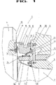
図1は、圧延ロールネック2の軸受部のオフセット、ロール胴側の封隙のための装置1を示している。圧延ロール4の圧延ロールネック2の上にロールネックスリーブ3が装着されている。このロールネックスリーブ3とスリーブリング5が結合、ここではねじ止めされている。このスリーブリング5は、しかしながら同様に、圧延ロール4と結合されていることも可能である。この圧延ロール4は、軸受スリーブ7を備えられているチョック6内において支持されている。
FIG. 1 shows an apparatus 1 for offset of the bearing part of the rolling
チョック6に、封隙要素8が、ねじ9を用いて解離可能に結合されている。同様にこの封隙要素8の構成要素でもあるリングシール10は、軸受スリーブ7とロールネックスリーブ3との間で流出する油が、この封隙要素8とチョック6との間の間隙を通して圧延ロール4へと到達可能でないための働きをする。この封隙要素8は、保持部11、延長部12から、および、この延長部12の端部における、2つの相互に離間する半径方向舌状部13、13′から成っている。これら半径方向舌状部13、13′は、スリーブリング5の封隙面14に当接している。
A
封隙要素8は、一体的に形成されるように、保持部11と結合された封隙舌状部15を有しており、この封隙舌状部が封隙機能部16に所属している。この封隙機能部16は、更に、L字形の輪郭体17を備えており、このL字形の輪郭体が、圧延ロール4の端側面18とねじ止めされている。この封隙舌状部15は、その際に、このL字形の第1の輪郭体17の脚部に封隙状態で当接している。このL字形の輪郭体17の第2の脚部は、この封隙要素8の1つの領域と共に、ラビリンス19を形成している。このラビリンス19および封隙舌状部15が、この封隙機能部16を形成している。
The sealing
保持部11および延長部12内において、接続部20が設けられており、この接続部を介して、油が、軸受スリーブ7とロールネックスリーブ3との間の軸受部から、半径方向舌状部13、13′の間の領域内へと到達可能である。この目的で、この保持部11内において、油捕捉ポケット21が形成されている。この接続部20および油捕捉ポケット21は、封隙要素8の上側の領域内における、ほぼ時計の12時の方向において配設されている。この油捕捉ポケット21は、側方で保持部11内へと、下方へと傾斜して指向する盲状穿孔として配設されている。この盲状穿孔開口部の下側の縁部22は、同時に、溢流口の役目を果たし、従って、この盲状穿孔の傾斜、およびこの盲状穿孔の底部へのこの下側の縁部22の高さによって、この油捕捉ポケット21内における油レベルが規定される。この油捕捉ポケット21は、その際に円形または長円形の盲状穿孔として形成されており、その際、この下側の縁部22は、本当はその場合に可能な限り、直線的な接線方向に延在する縁部として、形成されているべきである。
In the holding
油捕捉ポケット21内において捕捉された油は、接続部20を通って半径方向舌状部13、13′の間の領域内へと到達可能である。ここで、この油は、半径方向舌状部13の潤滑の役目を果たす。この半径方向舌状部13′は、直接的に軸受部からの油によって潤滑される。
Oil trapped in the
図2は、封隙要素8の下側の端部において更に別の第2の接続部25が設けられており、この接続部を通って過剰の油が半径方向舌状部13、13′と封隙面14との間の領域から流出することを示している。その際、この更に別の第2の接続部25は、小さな油溜まり26が、これら半径方向舌状部13、13′とこの封隙面14との間の領域内において保持されるように設けられている。
FIG. 2 shows that a further
図3は、封隙要素8および封隙舌状部15が確かに同様になお、一体的に形成されるように構成されてはいるが、しかしながら、封隙要素8として他の材料(異なるハッチングによって図示されている)から成っていることを示している。
FIG. 3 shows that the sealing
図4は、
封隙要素8が、単に保持部11、延長部12、および半径方向舌状部13、13′だけから成っていることを示している。封隙舌状部15′は、ねじ23を介して、この封隙要素8の保持部11と結合されている。従って、一般的に半径方向舌状部13、13′よりも大きな摩耗の影響下にあるこの封隙舌状部15′は、別個に交換可能である。
FIG.
It is shown that the sealing
保持部11が補強材を有することが可能であること、半径方向舌状部13、13′が補強のために被覆を有すること、または、同様にこれら封隙舌状部15、15′が強化ファイバーでもって織り込まれていることは図示されていない。
It is possible for the holding
半径方向舌状部13、13′は、剛性のばね24、または丸形鋼材要素を介して、形状において、常に封隙面14と半径方向舌状部13、13′との間の最適な封隙作用が保証されているような様式で保持されている。
The
1 装置
2 圧延ロールネック
3 ロールネックスリーブ
4 圧延ロール
5 スリーブリング
6 チョック
7 軸受スリーブ
8 封隙要素
9 ねじ
10 リングシール
11 保持部
12 延長部
13 半径方向舌状部
14 封隙面
15 封隙舌状部
16 封隙機能部
17 L字形の輪郭体
18 端側面
19 ラビリンス
20 接続部
21 油捕捉ポケット
22 縁部
23 ねじ
24 ばね
25 第2の接続部
26 油溜まり
DESCRIPTION OF SYMBOLS 1
Claims (10)
この圧延ロールネック(2)の上に装着されたロールネックスリーブ(3)を有し、このロールネックスリーブにスリーブリング(5)が設けられており、
チョック(6)内において軸受けされた軸受スリーブ(7)を有し、
このチョック(6)に保持部(11)を介して設けられた、スリーブリング(5)と協働する、半径方向舌状部(13、13′)を備える半径方向軸封隙材を有し、および、
圧延ロール(4)のロール胴に対して、この半径方向軸封隙材に設けられた封隙機能部(16)を有する様式の上記装置において、
保持部(11)、および半径方向舌状部(13、13′)が、解離不能に一体的に形成されるように、封隙要素(8)として構成されており、且つ封隙機能部(16)の封隙舌状部(15、15′)と共に1つのユニットを形成し、このユニットが、解離可能にチョックと封隙された状態で結合されていること、および、
封隙機能部(16)が、圧延ロール(4)の端側面(18)に沿って組み付けられているL字形の輪郭体(17)を有していること、
このL字形の輪郭体(17)の脚部と封隙要素(8)との間にラビリンス(19)が形成されていること、および、
封隙舌状部(15、15′)がこのL字形の輪郭体(17)の脚部に封隙状態で当接していること、
保持部(11)が延長部(12)を有しており、この延長部の端部に、スリーブリング(5)と封隙結合状態にある、少なくとも1つの半径方向舌状部(13、13′)が設けられていること、
保持部(11)および延長部(12)が、第1の接続部(20)を有しており、この接続部を介して、軸受部と反対側の半径方向舌状部(13)の、最低限の量の潤滑の目的のための僅かの量の油が、この軸受部の領域内における油捕捉ポケット(21)から、半径方向舌状部(13、13′)の間の領域内へと案内可能であること、および、
封隙要素(8)の下側の端部において第2の接続部(25)が設けられており、この第2の接続部を通って、過剰の油が半径方向舌状部(13、13′)と封隙面(14)との間の領域から流出可能であるように構成されていること、
を特徴とする装置。A device (1) for sealing the roll barrel side of the rolling roll neck (2) on the roll body side, the device comprising:
A roll neck sleeve (3) mounted on the rolled roll neck (2), and a sleeve ring (5) is provided on the roll neck sleeve;
A bearing sleeve (7) bearing in the chock (6);
The chock (6) has a radial axial seal with radial tongues (13, 13 ') which cooperates with the sleeve ring (5) provided via the holding part (11) ,and,
In the above-described apparatus having a sealing function part (16) provided in the radial axial sealing material with respect to the roll cylinder of the rolling roll (4),
The holding part (11) and the radial tongue (13, 13 ') are configured as a sealing element (8) so as to be integrally formed so as not to be dissociable , and the sealing function part ( 16) forming a unit with the gap tongues (15, 15 '), the unit being releasably coupled with the chock, and
The sealing function part (16) has an L-shaped profile (17) assembled along the end surface (18) of the rolling roll (4);
A labyrinth (19) is formed between the leg of the L-shaped profile (17) and the sealing element (8); and
The sealing tongue (15, 15 ') is in contact with the leg of the L-shaped profile (17) in a sealed state;
The holding part (11) has an extension (12), at the end of which at least one radial tongue (13, 13) which is in gap-engagement with the sleeve ring (5). ′) Is provided,
The holding part (11) and the extension part (12) have a first connection part (20), through which the radial tongue (13) on the opposite side of the bearing part, A small amount of oil for the purpose of a minimum amount of lubrication is from the oil catch pocket (21) in the region of this bearing part into the region between the radial tongues (13, 13 '). And being able to guide and
A second connection (25) is provided at the lower end of the sealing element (8), through which excess oil can be passed through the radial tongues (13, 13). ′) And being configured to be able to flow out of the area between the sealing surface (14),
A device characterized by.
前記補強材を用いて、一定の押圧力がこの封隙要素の耐用期間にわたって保証されることを特徴とする請求項1に記載の装置。The holding part (11) and / or the radial tongue (13, 13 ') and / or the sealing tongue (15, 15') have a reinforcement (24, 24 '). ,
The device according to claim 1 , characterized in that with the reinforcement, a constant pressing force is ensured over the lifetime of the sealing element .
第1の接続部(20)は、半径方向舌状部(13、13′)のそれぞれの上側の領域内において、圧延ロール(4)の軸線方向に見てほぼ時計の12時の方向の位置に設けられていること、および、
第2の接続部(25)が、半径方向舌状部(13、13′)のそれぞれの下側の領域内において、圧延ロール(4)の軸線方向に見て時計の6時の方向のちょっと手前またはちょっと過ぎの位置において設けられていることを特徴とする請求項1に記載の装置。 In the gap element (8) in the state incorporated in the chock (6) ,
The first connecting portion (20) is positioned approximately in the 12 o'clock direction of the watch as viewed in the axial direction of the rolling roll (4) in the upper region of each of the radial tongues (13, 13 '). Is provided , and
The second connecting part (25) is slightly in the 6 o'clock direction of the watch as viewed in the axial direction of the rolling roll (4) in the region below each of the radial tongues (13, 13 '). The device according to claim 1 , wherein the device is provided at a position before or slightly past .
Applications Claiming Priority (3)
| Application Number | Priority Date | Filing Date | Title |
|---|---|---|---|
| DE102004003763.9 | 2004-01-23 | ||
| DE102004003763A DE102004003763B4 (en) | 2004-01-23 | 2004-01-23 | Device for ball-side sealing of the bearing of a roll neck |
| PCT/EP2005/000427 WO2005071278A1 (en) | 2004-01-23 | 2005-01-18 | Device for sealing the ball side of a bearing of a roller stud |
Publications (3)
| Publication Number | Publication Date |
|---|---|
| JP2007518573A JP2007518573A (en) | 2007-07-12 |
| JP2007518573A5 JP2007518573A5 (en) | 2011-02-10 |
| JP4755603B2 true JP4755603B2 (en) | 2011-08-24 |
Family
ID=34800999
Family Applications (1)
| Application Number | Title | Priority Date | Filing Date |
|---|---|---|---|
| JP2006550008A Expired - Fee Related JP4755603B2 (en) | 2004-01-23 | 2005-01-18 | Device for sealing the roll barrel side of the rolling roll neck bearing |
Country Status (10)
| Country | Link |
|---|---|
| US (1) | US7836742B2 (en) |
| EP (1) | EP1706655B1 (en) |
| JP (1) | JP4755603B2 (en) |
| KR (1) | KR101087995B1 (en) |
| CN (1) | CN100434736C (en) |
| BR (1) | BRPI0506993A (en) |
| DE (1) | DE102004003763B4 (en) |
| RU (1) | RU2357118C2 (en) |
| WO (1) | WO2005071278A1 (en) |
| ZA (1) | ZA200605452B (en) |
Families Citing this family (12)
| Publication number | Priority date | Publication date | Assignee | Title |
|---|---|---|---|---|
| DE102007062863A1 (en) * | 2007-12-21 | 2009-06-25 | Heidelberger Druckmaschinen Ag | Device for clamping waves |
| RU2456105C1 (en) * | 2011-02-02 | 2012-07-20 | Открытое акционерное общество Акционерная холдинговая компания "Всероссийский научно-исследовательский и проектно-конструкторский институт металлургического машиностроения имени академика Целикова" (ОАО АХК "ВНИИМЕТМАШ") | Seal device of turning roller support |
| DE102011087605A1 (en) | 2011-12-01 | 2013-06-06 | Sms Siemag Ag | Chock and process for its manufacture |
| CN102494138B (en) * | 2011-12-15 | 2014-06-18 | 太原重工股份有限公司 | Roll neck sealing device of oil film bearing |
| RU2486977C1 (en) * | 2012-01-27 | 2013-07-10 | Открытое акционерное общество Акционерная холдинговая компания "Всероссийский научно-исследовательский и проектно-конструкторский институт металлургического машиностроения имени академика Целикова" (ОАО АХК "ВНИИМЕТМАШ") | Forming roll bearing seal |
| RU2505367C1 (en) * | 2012-10-24 | 2014-01-27 | Открытое акционерное общество Акционерная холдинговая компания "Всероссийский научно-исследовательский и проектно-конструкторский институт металлургического машиностроения имени академика Целикова" (ОАО АХК "ВНИИМЕТМАШ") | Sealing device of film-lubrication bearing |
| FR3005487B1 (en) * | 2013-05-13 | 2015-06-05 | Snecma | SEAL JOINT ASSEMBLY FOR A TURBOMACHINE COMPRISING LUBRICATION MEANS FOR A BRUSH SEAL |
| CN104455455A (en) * | 2014-12-06 | 2015-03-25 | 无锡高卓流体设备有限公司 | Bearing sealing piece |
| CN105526365B (en) * | 2015-12-25 | 2017-12-12 | 中车戚墅堰机车车辆工艺研究所有限公司 | Rotary seal structure |
| DE102017122269A1 (en) * | 2017-09-26 | 2019-03-28 | Schaeffler Technologies AG & Co. KG | Sealing arrangement, in particular for radial spherical plain bearings |
| CN112983992A (en) * | 2021-02-07 | 2021-06-18 | 太原重工股份有限公司 | Oil film bearing sealing device and rolling mill oil film bearing |
| CN113418006B (en) * | 2021-06-21 | 2023-02-28 | 太原重工股份有限公司 | Reverse waterproof device of oil film bearing |
Citations (2)
| Publication number | Priority date | Publication date | Assignee | Title |
|---|---|---|---|---|
| JPS4715881Y1 (en) * | 1969-03-13 | 1972-06-05 | ||
| EP1038601A2 (en) * | 1999-03-23 | 2000-09-27 | Kvaerner Metals Davy Limited | Sealing assembly |
Family Cites Families (19)
| Publication number | Priority date | Publication date | Assignee | Title |
|---|---|---|---|---|
| US3107718A (en) * | 1961-01-10 | 1963-10-22 | Abbey Etna Machine Co | Sectional forming roll for tube mills |
| AT324788B (en) | 1973-04-02 | 1975-09-25 | Simmerwerke Simmer Kg | RADIAL SHAFT SEAL |
| US4103406A (en) * | 1977-03-16 | 1978-08-01 | Hitachi Metals, Ltd. | Split type sectional forming roll |
| US4455856A (en) * | 1983-04-04 | 1984-06-26 | Morgan Construction Company | Coolant seal for rolling mill oil film bearing |
| IT1187539B (en) * | 1985-02-28 | 1987-12-23 | Danieli Off Mecc | LABYRINTH SEAL |
| DE3607729C3 (en) * | 1986-03-08 | 1995-06-29 | Skf Gmbh | Rolling bearing, for work rolls in high-speed rolling mills |
| US4790673A (en) * | 1987-03-30 | 1988-12-13 | Morgan Construction Company | Rock neck bearing assembly and inner bearing component therefor |
| FR2676943B1 (en) * | 1991-05-31 | 1994-01-07 | Clecim | EXTENDED TABLE ROLLER. |
| JPH0949572A (en) * | 1995-08-07 | 1997-02-18 | Koyo Seiko Co Ltd | Sealing device for rolling mill roll neck |
| DE29620018U1 (en) * | 1996-11-18 | 1998-01-08 | Kark, Uwe, 21149 Hamburg | Roller bearings for roll stands |
| DE19713333C2 (en) * | 1997-03-29 | 2000-01-13 | Fag Automobiltechnik Ag | Rolling bearing attachment |
| IT1294864B1 (en) * | 1997-09-12 | 1999-04-23 | Skf Ind Spa | SEALING COMPLEX FOR A ROLLING BEARING. |
| DE29805241U1 (en) * | 1998-03-23 | 1999-08-12 | Kark, Uwe, 21149 Hamburg | Roller bearings for roll stands |
| DE29904179U1 (en) * | 1999-03-08 | 1999-06-24 | Skf Gmbh, 97421 Schweinfurt | Sealing arrangement for a machine part |
| GB9914442D0 (en) * | 1999-06-22 | 1999-08-18 | Kvaerner Metals Davy Ltd | Sealing assembly |
| DE10113593A1 (en) * | 2001-03-20 | 2002-09-26 | Sms Demag Ag | Seal for bearing for roller comprises bush fitted on roller shaft which cooperates with flexible sealing rings to form sealing labyrinth with C-profile ring attached to roller face |
| CN2517903Y (en) * | 2001-12-27 | 2002-10-23 | 太原重型机械(集团)有限公司 | Multi-lip sealing device of film lubrication bearing |
| DE10211665A1 (en) * | 2002-03-15 | 2003-10-02 | Sms Demag Ag | sealing device |
| DE10316316A1 (en) * | 2003-04-10 | 2004-10-21 | Sms Demag Ag | Device for returning oil in roller bearings |
-
2004
- 2004-01-23 DE DE102004003763A patent/DE102004003763B4/en not_active Expired - Lifetime
-
2005
- 2005-01-18 US US10/586,985 patent/US7836742B2/en active Active
- 2005-01-18 CN CNB2005800031047A patent/CN100434736C/en active Active
- 2005-01-18 BR BRPI0506993-9A patent/BRPI0506993A/en not_active IP Right Cessation
- 2005-01-18 EP EP05701001.9A patent/EP1706655B1/en active Active
- 2005-01-18 RU RU2006130371/11A patent/RU2357118C2/en not_active IP Right Cessation
- 2005-01-18 WO PCT/EP2005/000427 patent/WO2005071278A1/en active Application Filing
- 2005-01-18 KR KR1020067015614A patent/KR101087995B1/en not_active IP Right Cessation
- 2005-01-18 JP JP2006550008A patent/JP4755603B2/en not_active Expired - Fee Related
-
2006
- 2006-07-03 ZA ZA200605452A patent/ZA200605452B/en unknown
Patent Citations (2)
| Publication number | Priority date | Publication date | Assignee | Title |
|---|---|---|---|---|
| JPS4715881Y1 (en) * | 1969-03-13 | 1972-06-05 | ||
| EP1038601A2 (en) * | 1999-03-23 | 2000-09-27 | Kvaerner Metals Davy Limited | Sealing assembly |
Also Published As
| Publication number | Publication date |
|---|---|
| RU2357118C2 (en) | 2009-05-27 |
| US20070290448A1 (en) | 2007-12-20 |
| KR101087995B1 (en) | 2011-12-01 |
| BRPI0506993A (en) | 2007-07-03 |
| DE102004003763A1 (en) | 2005-08-18 |
| ZA200605452B (en) | 2007-10-31 |
| EP1706655B1 (en) | 2016-10-12 |
| CN1926348A (en) | 2007-03-07 |
| KR20060127967A (en) | 2006-12-13 |
| EP1706655A1 (en) | 2006-10-04 |
| RU2006130371A (en) | 2008-02-27 |
| JP2007518573A (en) | 2007-07-12 |
| DE102004003763B4 (en) | 2005-10-20 |
| WO2005071278A1 (en) | 2005-08-04 |
| CN100434736C (en) | 2008-11-19 |
| US7836742B2 (en) | 2010-11-23 |
Similar Documents
| Publication | Publication Date | Title |
|---|---|---|
| JP4755603B2 (en) | Device for sealing the roll barrel side of the rolling roll neck bearing | |
| JP2007518573A5 (en) | ||
| JP5620016B2 (en) | Oil scraper ring and oil scraper assembly | |
| US1075551A (en) | Lubricator for vehicle-wheels. | |
| US1947198A (en) | Floating stuffing box | |
| EA016414B1 (en) | Roller for conveyer and seal for use in such roller | |
| JPWO2020090305A1 (en) | Cylindrical roller bearing | |
| CN103154544A (en) | Assembly for sealing a rotational connection | |
| JP2006515805A (en) | Chock to accommodate rolling roll neck | |
| DK2837872T3 (en) | bearing device | |
| CN109563883B (en) | Joint device for articulated shaft | |
| US905631A (en) | Lubricating-bearing for steam-turbines or the like. | |
| CN205446388U (en) | Large -scale cement of compound guide of holder self -aligning roller bearing for roll squeezer | |
| CN110439930A (en) | A kind of novel friction pair structure of sliding bearing and axis | |
| US133316A (en) | Improvement in lubricators | |
| US60925A (en) | It may concern | |
| CN213711645U (en) | Wear-resistant shaft bushing for zinc pot | |
| US119287A (en) | Improvement in lubricating loose pulleys | |
| CN216842677U (en) | Sealed slewing bearing capable of rotating oppositely | |
| US117845A (en) | Improvement in oiling journals | |
| CN208793453U (en) | A kind of new-type rolling bearing | |
| JP2010286030A (en) | Oil receiver | |
| CA2962405C (en) | Bearing system for dynamically varying loads | |
| RU2630993C2 (en) | Roller bearing of sintering trolley of agglomeration machine | |
| US1084922A (en) | Lubricating device. |
Legal Events
| Date | Code | Title | Description |
|---|---|---|---|
| A621 | Written request for application examination |
Free format text: JAPANESE INTERMEDIATE CODE: A621 Effective date: 20071221 |
|
| RD04 | Notification of resignation of power of attorney |
Free format text: JAPANESE INTERMEDIATE CODE: A7424 Effective date: 20100517 |
|
| A977 | Report on retrieval |
Free format text: JAPANESE INTERMEDIATE CODE: A971007 Effective date: 20100726 |
|
| A131 | Notification of reasons for refusal |
Free format text: JAPANESE INTERMEDIATE CODE: A131 Effective date: 20100824 |
|
| A601 | Written request for extension of time |
Free format text: JAPANESE INTERMEDIATE CODE: A601 Effective date: 20101111 |
|
| A602 | Written permission of extension of time |
Free format text: JAPANESE INTERMEDIATE CODE: A602 Effective date: 20101118 |
|
| A524 | Written submission of copy of amendment under article 19 pct |
Free format text: JAPANESE INTERMEDIATE CODE: A524 Effective date: 20101213 |
|
| A01 | Written decision to grant a patent or to grant a registration (utility model) |
Free format text: JAPANESE INTERMEDIATE CODE: A01 Effective date: 20110510 |
|
| A01 | Written decision to grant a patent or to grant a registration (utility model) |
Free format text: JAPANESE INTERMEDIATE CODE: A01 |
|
| A61 | First payment of annual fees (during grant procedure) |
Free format text: JAPANESE INTERMEDIATE CODE: A61 Effective date: 20110527 |
|
| FPAY | Renewal fee payment (event date is renewal date of database) |
Free format text: PAYMENT UNTIL: 20140603 Year of fee payment: 3 |
|
| R150 | Certificate of patent or registration of utility model |
Free format text: JAPANESE INTERMEDIATE CODE: R150 |
|
| R250 | Receipt of annual fees |
Free format text: JAPANESE INTERMEDIATE CODE: R250 |
|
| R250 | Receipt of annual fees |
Free format text: JAPANESE INTERMEDIATE CODE: R250 |
|
| R250 | Receipt of annual fees |
Free format text: JAPANESE INTERMEDIATE CODE: R250 |
|
| R250 | Receipt of annual fees |
Free format text: JAPANESE INTERMEDIATE CODE: R250 |
|
| LAPS | Cancellation because of no payment of annual fees |