JP4748802B2 - Molding machine - Google Patents

Molding machine Download PDF

Info

Publication number
JP4748802B2
JP4748802B2 JP2006322965A JP2006322965A JP4748802B2 JP 4748802 B2 JP4748802 B2 JP 4748802B2 JP 2006322965 A JP2006322965 A JP 2006322965A JP 2006322965 A JP2006322965 A JP 2006322965A JP 4748802 B2 JP4748802 B2 JP 4748802B2
Authority
JP
Japan
Prior art keywords
mold
sub
clamping device
mold clamping
transport
Prior art date
Legal status (The legal status is an assumption and is not a legal conclusion. Google has not performed a legal analysis and makes no representation as to the accuracy of the status listed.)
Expired - Fee Related
Application number
JP2006322965A
Other languages
Japanese (ja)
Other versions
JP2008137170A (en
Inventor
幸三 日比
健二 福本
正清 河野
太 水田
悟春 西野
Original Assignee
株式会社名機製作所
Priority date (The priority date is an assumption and is not a legal conclusion. Google has not performed a legal analysis and makes no representation as to the accuracy of the date listed.)
Filing date
Publication date
Application filed by 株式会社名機製作所 filed Critical 株式会社名機製作所
Priority to JP2006322965A priority Critical patent/JP4748802B2/en
Publication of JP2008137170A publication Critical patent/JP2008137170A/en
Application granted granted Critical
Publication of JP4748802B2 publication Critical patent/JP4748802B2/en
Expired - Fee Related legal-status Critical Current
Anticipated expiration legal-status Critical

Links

Images

Landscapes

  • Moulds For Moulding Plastics Or The Like (AREA)
  • Injection Moulding Of Plastics Or The Like (AREA)

Description

本発明は、直交して開口する開口部から搬入・搬出する複数の副型締装置の一を圧締する圧締部を有する縦型の主型締装置と、前記開口部の外方に待機・配置され、前記主型締装置の圧締力より低い圧締力で金型を圧締するとともに該金型を開放可能な複数の前記副型締装置と、前記副型締装置の待機する前記開口部外方と前記主型締装置の前記圧締部との間で前記副型締装置を搬送する搬送装置とを備えた成形機に関するものである。   The present invention relates to a vertical main mold clamping device having a pressure clamping unit that clamps one of a plurality of sub mold clamping devices that are carried in and out from an opening that opens at right angles, and a standby outside the opening. A plurality of the sub mold clamping devices that are arranged and that can clamp the mold with a clamping force lower than the clamping force of the main mold clamping device and can open the mold, and the sub mold clamping device waits. The present invention relates to a molding machine including a conveying device that conveys the auxiliary mold clamping device between the outside of the opening and the pressure clamping portion of the main mold clamping device.

複数の副型締装置を主型締装置内へ順次搬入・搬出して高効率に成形する成形装置は、特許文献1と特許文献2に開示されている。特許文献1は、金型開閉手段を上下に備えた一対の副型締機構と、それら副型締機構を横方向に移動自在に載置した機台と、副型締機構の両方が停止位置する機台中央部に配設した竪型の主型締機構と、両副型締装置を同時に移動して主型締機構内に副型締機構を交互に出入する機台側の駆動手段と、各副型締機構に上下に分割して取付けられた二組の金型とからなり、上記主型締機構は機台上方の上部受圧板と機台内の下部受圧板とを、機台に固定したタイバーにより一体に結合し、その下部受圧板に型締ラムを設けて構成され、かつ上部受圧板に射出装置を下向きに備えることを特徴とする交互式射出成形機に関するものである。しかしながら、特許文献1の技術によれば、二の副型締機構を備えるものであり、より成形効率を上げるために副型締機構を三以上備えたものではない。したがって、副型締機構の移動は直交しない直線状のみであり、駆動手段はボールねじが採用されている。   Patent Document 1 and Patent Document 2 disclose a molding apparatus that efficiently carries in and out a plurality of sub mold clamping apparatuses in and out of the main mold clamping apparatus. Patent Document 1 discloses that a pair of sub mold clamping mechanisms provided with upper and lower mold opening / closing means, a machine base on which the sub mold clamping mechanisms are mounted so as to be movable in the lateral direction, and the sub mold clamping mechanism are both stopped positions. A vertical main mold clamping mechanism disposed in the center of the machine base, and a drive means on the machine base side that alternately moves the sub mold clamping mechanisms into and out of the main mold clamping mechanism by moving both sub mold clamping devices simultaneously. The main mold clamping mechanism consists of an upper pressure plate above the machine base and a lower pressure plate in the machine base. The present invention relates to an alternating injection molding machine characterized in that it is integrally connected by a tie bar fixed to a lower plate, a clamping ram is provided on the lower pressure receiving plate, and an injection device is provided downward on the upper pressure receiving plate. However, according to the technique of Patent Document 1, two sub-clamping mechanisms are provided, and three or more sub-clamping mechanisms are not provided in order to further increase molding efficiency. Therefore, the movement of the sub mold clamping mechanism is only a straight line that is not orthogonal, and a ball screw is adopted as the driving means.

特許文献2は、直交して開口する開口部から搬入・搬出する複数の副型締装置の一を圧締する圧締部を有する縦型の主型締装置と、前記開口部の外方に待機・配置され、前記主型締装置の圧締力より低い圧締力で金型を圧締するとともに該金型を開放可能な複数の前記副型締装置とを備えた射出成形機を開示しているが、前記副型締装置の待機する前記開口部外方と前記主型締装置の前記圧締部との間で前記副型締装置を搬送する搬送装置に関して開示していない。   Patent Document 2 discloses a vertical main mold clamping device having a pressure clamping unit that clamps one of a plurality of sub mold clamping devices that are carried in and out from an opening that opens orthogonally, and an outer side of the opening. Disclosed is an injection molding machine provided with a plurality of sub-clamping devices that are placed on standby and arranged to clamp a mold with a clamping force lower than the clamping force of the main mold clamping device and to open the mold. However, there is no disclosure regarding a conveying device that conveys the sub mold clamping device between the outside of the opening that the sub mold clamping device stands by and the pressure clamping portion of the main mold clamping device.

特公平8−5089号公報Japanese Patent Publication No. 8-5089 米国特許公開公報 US2006/0172039A1US Patent Publication US2006 / 0172039A1

本発明は、上記の事情を鑑みてなされたものであって、副型締装置の搬送を効果的に行い成形作業を高効率に実施できる成形装置を提供することを目的とする。   The present invention has been made in view of the above circumstances, and an object of the present invention is to provide a molding apparatus that can efficiently transport a sub-clamping apparatus and perform a molding operation with high efficiency.

本発明は、直交して開口する開口部から搬入・搬出する複数の副型締装置の一を圧締する圧締部を有する縦型の主型締装置と、前記開口部の外方に待機・配置され、前記主型締装置の圧締力より低い圧締力で金型を圧締するとともに該金型を開放可能な複数の前記副型締装置と、前記副型締装置の待機する前記開口部外方と前記主型締装置の前記圧締部との間で型閉じしている副型締装置を搬送する搬送装置とを備えた成形機において、前記搬送装置は、前記副型締装置を載置する搬送台と、該搬送台の下面に固設した複数のレールと、該レールと当接し案内して回動する複数の搬送ローラと、該複数の搬送ローラを架台上面で軸支する支持枠とからなり、前記搬送装置の搬送台に載置される副型締装置は、昇降移動し下面に上金型を取り付けた上型板と搬送台に載置され上面に下金型を取り付けた下型板とが設けられ、前記上型板と下型板との間には副シリンダ装置と、案内筒の内孔に案内され上型板の昇降を案内するロッドが設けられることを特徴とする成形機に関する。 The present invention relates to a vertical main mold clamping device having a pressure clamping unit that clamps one of a plurality of sub mold clamping devices that are carried in and out from an opening that opens at right angles, and a standby outside the opening. A plurality of the sub mold clamping devices that are arranged and that can clamp the mold with a clamping force lower than the clamping force of the main mold clamping device and can open the mold, and the sub mold clamping device waits. In a molding machine comprising a transport device that transports a sub mold clamping device that is closed between the outside of the opening and the pressure clamping portion of the main mold clamping device, the transport device is the sub mold A conveying table on which the fastening device is placed, a plurality of rails fixed to the lower surface of the conveying table, a plurality of conveying rollers that abut against the rail and rotate while being guided, and the plurality of conveying rollers on the upper surface of the gantry consists of a support frame for rotatably supporting the auxiliary clamping device which is placed on the conveying platform of the transport apparatus, the lifting movement Attach the upper die to the lower surface And upper die plate and the lower die plate attached to the lower die is provided placed on the upper surface to the transfer table, and the sub-cylinder device between the upper mold plate and the lower die plate, the inner hole of the guide tube The present invention relates to a molding machine characterized in that a rod is provided for guiding the raising and lowering of the upper mold plate.

本発明の成形機によれば、副型締装置の搬送を効果的に行うことができ成形作業を高効率に実施できる。 According to the molding machine of the present invention, the auxiliary mold clamping device can be effectively conveyed, and the molding operation can be performed with high efficiency.

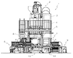
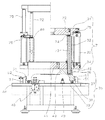
図面に基づいて、本発明の実施の形態を詳細に説明する。図1は、本発明の射出成形機の全体を示す正面図である。図2は、副型締装置を圧締する主型締装置とその上に設けた射出装置を示す正面図である。図3は、図1において副型締装置が存在しない状態のA−A矢視断面平面図である。図4は、図3におけるB−B矢視断面側面図である。図5は、図3におけるC−C矢視部分断面正面図である。図6は、図3におけるD−D矢視断面側面図である。図7は、図2において射出装置が揺動し副型締装置が搬出されたときのパージ材排出手段を含む正面図である。   Embodiments of the present invention will be described in detail with reference to the drawings. FIG. 1 is a front view showing the entire injection molding machine of the present invention. FIG. 2 is a front view showing a main mold clamping apparatus for clamping the sub mold clamping apparatus and an injection apparatus provided thereon. FIG. 3 is a cross-sectional plan view taken along the line AA in FIG. 4 is a cross-sectional side view taken along the line B-B in FIG. 3. FIG. 5 is a partial cross-sectional front view taken along the line CC in FIG. 6 is a sectional side view taken along the line DD in FIG. FIG. 7 is a front view including purge material discharging means when the injection device swings in FIG. 2 and the sub mold clamping device is carried out.

図1乃至図5に示すように、射出成形機1は、射出装置2と、射出装置2を油圧駆動する駆動装置3と、射出装置2の下部に配設された主型締装置10と、主型締装置10の水平方向四方へ直交して開口する開口部の隣接する外方に設けられた架台44と、主型締装置10内部の開口部で囲まれた圧締部と架台44との間で副型締装置7を搬送する搬送装置35と、主型締装置10及び二の副型締装置7を油圧駆動する駆動装置9と、二の副型締装置7を油圧駆動する駆動装置8とからなり、射出装置2の周囲には射出装置2への材料供給・保守・点検等に供する足場台5が設けられ、足場台5の外周縁には転落防止用のフェンス4が立設され、足場台5には昇降用の梯子6が接続されている。   As shown in FIGS. 1 to 5, the injection molding machine 1 includes an injection device 2, a drive device 3 that hydraulically drives the injection device 2, a main mold clamping device 10 disposed below the injection device 2, A base 44 provided on the outer side adjacent to the opening that is orthogonal to the horizontal direction of the main mold clamping device 10, and a pressure clamping unit and the base 44 surrounded by the opening inside the main mold clamping device 10. A conveying device 35 for conveying the sub mold clamping device 7 between them, a drive device 9 for hydraulically driving the main mold clamping device 10 and the second sub mold clamping device 7, and a drive for hydraulically driving the second sub mold clamping device 7. The scaffold 8 is provided around the injection device 2 for material supply, maintenance, inspection, etc. to the injection device 2, and a fence 4 for preventing fall is provided on the outer periphery of the scaffold 5. A ladder 6 for raising and lowering is connected to the scaffold base 5.

主型締装置10は、図2に示すように、架台ともなる下盤26と、下盤26の中央部に設けられた主シリンダ27と、主シリンダ27に往復動自在に嵌挿されたラム25と、下盤26の四隅に立設された四のタイバ24と、タイバ24の上端部を四隅で固着する上盤23とからなる縦型の型締装置である。隣接する二のタイバ24の内側面と、下盤26の上面と、上盤23の下面とで開口部が形成され、四面形成される開口部はそれぞれ直交することになる。また、四面の開口部と、下盤26の上面と、上盤23の下面とで囲まれた領域で圧締部が形成される。圧締部には副型締装置7が搬入・搬出され、副型締装置7が圧締部の所定位置に位置決めされたとき、ラム25が上昇して下型板34を押圧し、上型板31の下面に取り付けた上金型28と下型板34の上面に取り付けた下金型29とを圧締する。なお、図3に示すように、ラム25の端部には、ラム25の位置を検出する位置検出器60と、ラム25のオーバーランを検出するリミットスイッチ61と、ラム25の回転を防止する回り止め具62とが設けられている。   As shown in FIG. 2, the main mold clamping device 10 includes a lower plate 26 that also serves as a gantry, a main cylinder 27 that is provided at the center of the lower plate 26, and a ram that is removably fitted into the main cylinder 27. 25, a vertical mold clamping device including four tie bars 24 erected at the four corners of the lower board 26, and an upper board 23 that fixes the upper ends of the tie bars 24 at the four corners. Openings are formed by the inner side surfaces of the two adjacent tie bars 24, the upper surface of the lower plate 26, and the lower surface of the upper plate 23, and the openings formed on four sides are orthogonal to each other. Further, the pressing portion is formed in a region surrounded by the four openings, the upper surface of the lower plate 26, and the lower surface of the upper plate 23. When the sub mold clamping device 7 is carried into and out of the pressure clamping portion, and the sub mold clamping device 7 is positioned at a predetermined position of the pressure clamping portion, the ram 25 rises and presses the lower mold plate 34, and the upper mold The upper mold 28 attached to the lower surface of the plate 31 and the lower mold 29 attached to the upper surface of the lower mold plate 34 are clamped together. As shown in FIG. 3, at the end of the ram 25, a position detector 60 for detecting the position of the ram 25, a limit switch 61 for detecting an overrun of the ram 25, and the rotation of the ram 25 are prevented. A rotation stopper 62 is provided.

副型締装置7は、図2及び図5に示すように、搬送装置35の搬送台36に載置される下型板34と、下型板34の四隅に立設され搬送台36の四隅に穿孔された係合孔46に摺動自在に嵌挿する案内筒32と、案内筒32の内孔に案内されて昇降するロッド72と、複数のロッド72の上端部を固着する上型板31と、上型板31及び下型板34それぞれの軸対称に二設けた張り出し部を連結するように設けた副シリンダ装置33とからなる。二の副シリンダ装置33の合計した圧締出力は、主型締装置10の一のラム25の圧締出力よりも小さくなるように構成されている。ロッド72の中心部にはロッド72の下端面に開口しロッド72の上部側面に取り付けた通気口74に連通する中心孔73が穿孔されており、ロッド72の移動に伴う空気の吸引と排気を容易にしている。副シリンダ装置33を上昇駆動すると、ロッド75が伸長し上型板31が上昇して、図5の右側に断面で記載の閉状態から左側に記載の開放状態になる。このとき、上型板31の昇降を案内する複数のロッド72のうち少なくとも一の中間部に設けた環状溝80が露出し、係止装置76の爪がこの環状溝80に係合して上型板31の落下を防止する。係止装置76は、エアシリンダで任意の時期に爪を開閉するものであり、環状溝とともに安全装置を構成する。また、下型板34に設けられた係止ピン41は、副型締装置7が架台44の所定位置に位置決めされ、架台44の下部に設けられたエジェクタ装置47が貫通孔40を貫通して成形品を突き上げ作動したとき、下型板34も突き上げられることがないように下型板34を搬送台36に係止するためのものである。   As shown in FIGS. 2 and 5, the sub mold clamping device 7 includes a lower mold plate 34 placed on the conveyance table 36 of the conveyance device 35, and four corners of the conveyance table 36 erected on the four corners of the lower mold plate 34. A guide cylinder 32 that is slidably inserted into an engagement hole 46 pierced in the shaft, a rod 72 that is guided by an inner hole of the guide cylinder 32, and an upper mold plate that fixes the upper ends of the plurality of rods 72 to each other. 31 and a sub-cylinder device 33 provided so as to connect two projecting portions provided symmetrically with respect to each of the upper mold plate 31 and the lower mold plate 34. The total pressing output of the second sub cylinder device 33 is configured to be smaller than the pressing output of one ram 25 of the main mold clamping device 10. A central hole 73 that opens at the lower end surface of the rod 72 and communicates with a vent hole 74 attached to the upper side surface of the rod 72 is perforated at the center of the rod 72, and sucks and exhausts air as the rod 72 moves. Making it easy. When the sub-cylinder device 33 is driven upward, the rod 75 extends and the upper mold plate 31 rises, and the closed state shown in the cross section on the right side of FIG. 5 is changed to the open state shown on the left side. At this time, the annular groove 80 provided in at least one intermediate portion of the plurality of rods 72 that guide the raising and lowering of the upper mold plate 31 is exposed, and the claw of the locking device 76 engages with the annular groove 80 and moves upward. The fall of the template 31 is prevented. The locking device 76 is an air cylinder that opens and closes the pawl at an arbitrary time, and constitutes a safety device together with the annular groove. Further, the locking pin 41 provided on the lower mold plate 34 has the sub mold clamping device 7 positioned at a predetermined position of the gantry 44, and an ejector device 47 provided at the lower part of the gantry 44 passes through the through hole 40. When the molded product is pushed up, the lower mold plate 34 is locked to the transport table 36 so that the lower mold plate 34 is not pushed up.

搬送装置35は、副型締装置7をそれが待機する開口部外方と主型締装置10内の圧締部との間で搬送する。搬送装置35は、図3乃至図6に示すように、主型締装置10の架台ともなる下盤26の上面とその上面に同じ高さで下盤26の四辺に隣接して配設された架台44上面とに跨設された断面コ字状の支持枠39と、支持枠39の対向辺にその端面から突出するように等間隔で軸支された複数の搬送ローラ38と、搬送ローラ38の幅と略同一寸法で当接するレール37と、レール37を脚部下面に固設し四隅に副型締装置7の案内筒32を嵌挿する係合孔46を有し中央部に主型締装置10のラム25が遊貫する貫通孔40を有する搬送台36とからなる。なお、レール37は、その幅を搬送ローラ38の幅と略同一にするためと材質を考慮するために搬送台36とは別部材で構成した実施態様を示したが、搬送台36の一部を加工してレール37を搬送台36と一体に構成してもよい。   The conveying device 35 conveys the auxiliary mold clamping device 7 between the outside of the opening where it waits and the pressure clamping unit in the main mold clamping device 10. As shown in FIGS. 3 to 6, the conveying device 35 is disposed adjacent to the four sides of the lower plate 26 at the same height as the upper surface of the lower plate 26 that also serves as a frame for the main mold clamping device 10. A support frame 39 having a U-shaped cross-section straddling the top surface of the gantry 44, a plurality of transport rollers 38 that are axially supported on the opposite sides of the support frame 39 so as to protrude from the end surfaces thereof, and the transport rollers 38 The rail 37 abuts with substantially the same size as the width of the rail, the rail 37 is fixed to the lower surface of the leg portion, and the engagement hole 46 for inserting the guide cylinder 32 of the auxiliary mold clamping device 7 is inserted into the four corners. The ram 25 of the fastening device 10 includes a transport table 36 having a through hole 40 through which the ram 25 penetrates. In addition, although the rail 37 showed the embodiment comprised from the conveyance stand 36 in order to make the width | variety substantially the same with the width | variety of the conveyance roller 38, and to consider the material, a part of conveyance stand 36 was shown. Alternatively, the rail 37 may be integrated with the carriage 36.

搬送装置35は、図3に示すように、下盤26の上面で直交している。搬送装置35の直交部分は、図4に示すように、支持枠39で支持される搬送ローラ同士の中心間隔Rの中に、それと直交する支持枠39に支持された搬送ローラの幅方向が入るように配設されている。このように構成することにより、一方向の搬送台36の搬送と、一方向と直交する他方向の搬送台36の搬送とを互いに干渉したり乗り上げたりすることなく平滑に実行させることができる。なお、図3及び図4に示すように、圧締部である下盤26の上面における支持枠39は、ラム25を矩形に取り囲むように配設されている。この場合、支持枠39相互の連絡部分は、支持枠39の端面間に搬送ローラ38同士の中心間隔Rよりも小さい間隙Gを設けて不連続となるように形成されている。この間隙Gは支持枠39が直交する部分に設けても良い。このように構成することにより、ラム25に設けられている位置検出器60やリミットスイッチ61等への電線63を容易に配線することができる。   The conveying device 35 is orthogonal to the upper surface of the lower board 26 as shown in FIG. As shown in FIG. 4, in the orthogonal portion of the transport device 35, the width direction of the transport roller supported by the support frame 39 orthogonal to the center interval R between the transport rollers supported by the support frame 39 is included. It is arranged like this. By configuring in this way, it is possible to smoothly execute the conveyance of the conveyance table 36 in one direction and the conveyance of the conveyance table 36 in the other direction orthogonal to the one direction without interfering with each other and riding on. As shown in FIGS. 3 and 4, the support frame 39 on the upper surface of the lower plate 26 serving as a pressing portion is disposed so as to surround the ram 25 in a rectangular shape. In this case, the communication part between the support frames 39 is formed to be discontinuous by providing a gap G smaller than the center distance R between the conveying rollers 38 between the end faces of the support frame 39. The gap G may be provided in a portion where the support frame 39 is orthogonal. With this configuration, the electric wire 63 to the position detector 60, the limit switch 61, and the like provided in the ram 25 can be easily wired.

搬送装置35の搬送駆動手段48は、サーボモータ64で可変速駆動されるポンプ65と、タンク66の作動油をポンプ65が吐出して発生した圧油により進退駆動されるシリンダ装置67と、搬送台36の位置を検出する位置検出器49とからなる。サーボモータ64、ポンプ65及びタンク66は、コンパクトに纏められて一体となり、架台44に固着されている。ポンプ65からの二の管路は架台44に固着されたシリンダ装置67のシリンダにそれぞれ接続されている。搬送駆動手段48の図示しない制御装置は、目標信号に応じて正逆所定の回転速度でサーボモータ64を回転駆動し、シリンダ装置67のロッドを進退させる。ロッドは継手68を介して搬送台36に接続されており、搬送台36の位置は位置検出器49で制御装置に入力されているので、搬送台36は閉ループにより目標信号に応じた正確な速度で位置決め制御される。このように構成された搬送駆動手段48は、サーボモータとボール螺子で構成したものより低コストであり、衝撃緩衝装置等を要せずに加速・減速時の衝撃を最小限に抑えつつ高速搬送を可能とする。   The transport driving means 48 of the transport device 35 includes a pump 65 that is driven at a variable speed by a servo motor 64, a cylinder device 67 that is driven back and forth by pressure oil generated by the pump 65 discharging hydraulic oil from the tank 66, and a transport It comprises a position detector 49 for detecting the position of the table 36. The servo motor 64, the pump 65, and the tank 66 are integrated in a compact manner and are united and fixed to the gantry 44. Two pipe lines from the pump 65 are respectively connected to cylinders of a cylinder device 67 fixed to the gantry 44. A control device (not shown) of the transport driving means 48 drives the servo motor 64 to rotate at a predetermined forward / reverse rotation speed in accordance with the target signal, and moves the rod of the cylinder device 67 forward and backward. Since the rod is connected to the transport table 36 via a joint 68, and the position of the transport table 36 is input to the control device by the position detector 49, the transport table 36 is closed at an accurate speed according to the target signal. Positioning is controlled by. The conveyance driving means 48 configured in this manner is lower in cost than that constituted by a servo motor and a ball screw, and does not require an impact buffering device or the like, and is capable of high-speed conveyance while minimizing impact during acceleration / deceleration. Is possible.

搬送台36の搬送移動は、その荷重方向の案内は上記のようにレール37と搬送ローラ38で行われるが、水平方向の案内は、搬送台36の両側面に当接して回転する複数の案内ローラ51を軸支する支持板50をそれぞれの架台44上面で支持枠39に平行して配設することにより行われる。そして、一方の支持板50は、搬送方向に直交する方向へ調整具52により微小移動させて最適な案内状態が得られるようにしている。架台44に隣接する下盤26上面の四隅近傍における搬送台36の水平方向の案内は、搬送台36の両側面に当接して回転する複数の案内ローラ54を軸支する直角L字状の支持板53を下盤26上面四隅で支持枠39に平行して配設することにより行われる。また、下盤26上面中央部における搬送台36の水平方向の案内は、搬送台36の両側面に当接して回転する複数の案内ローラ56,59を軸支する支持板55,58を下盤26上面中央部で支持枠39に平行して配設することにより行われる。そして、一方の支持板55,58は、搬送方向に直交する方向へ調整具57により微小移動させて最適な案内状態が得られるようにしている。搬送台36の搬送移動は、待機位置であってエジェクタ装置47が作動可能な、搬送台36の外方端面が衝止部43,78に当接する所定位置と、圧締部で主型締装置10が副型締装置7を圧締可能な、継手68が衝止部42,77に当接する所定位置との間を往復して行われる。このように構成しているので、搬送駆動手段48が、図5に示すように、搬送台36の搬送方向に直交する方向の中心に設けられていなくても、搬送台36を横ずれなく安定して駆動することが可能となる。   The transport movement of the transport table 36 is guided by the rail 37 and the transport roller 38 as described above, but the horizontal guide is a plurality of guides rotating in contact with both side surfaces of the transport table 36. This is done by disposing the support plate 50 that supports the roller 51 in parallel with the support frame 39 on the upper surface of each gantry 44. The one support plate 50 is finely moved by the adjustment tool 52 in a direction orthogonal to the transport direction so that an optimum guide state is obtained. The horizontal guide of the transport table 36 in the vicinity of the four corners of the upper surface of the lower board 26 adjacent to the gantry 44 is a right-angled L-shaped support that pivotally supports a plurality of guide rollers 54 that rotate in contact with both side surfaces of the transport table 36. This is done by arranging the plate 53 in parallel with the support frame 39 at the four corners of the upper surface of the lower board 26. Further, the horizontal guide of the transport table 36 at the center of the upper surface of the lower plate 26 is provided by supporting plates 55 and 58 that pivotally support a plurality of guide rollers 56 and 59 rotating in contact with both side surfaces of the transport table 36. 26 is arranged in parallel with the support frame 39 at the center of the upper surface. Then, one of the support plates 55 and 58 is finely moved by the adjustment tool 57 in a direction orthogonal to the transport direction so that an optimum guide state is obtained. The conveyance movement of the conveyance table 36 is a standby position and the main mold clamping device at a predetermined position where the outer end surface of the conveyance table 36 abuts against the stop portions 43 and 78, where the ejector device 47 can operate, and the pressure clamping unit. 10 is reciprocating between a predetermined position at which the joint 68 is capable of pressing the sub mold clamping device 7 and the joint 68 abuts against the stop portions 42 and 77. With this configuration, even if the transport driving means 48 is not provided at the center in the direction orthogonal to the transport direction of the transport table 36 as shown in FIG. Can be driven.

射出装置2は、主型締装置10の上盤23上面に立設した基体21と、基体21に摺動して案内される複数のロッド19と、ロッド19の上端部を固着する平面視ロ字状の基盤16と、基盤16の対向側面を貫通して設けられる旋回軸17と、旋回軸17に揺動自在に支持される連結体14と、連結体14の下面にその垂直軸に同心に立設され図示しないスクリュを嵌挿する加熱筒18と、加熱筒18の先端に螺設されたノズル20と、連結体14に設けられ加熱筒18に嵌挿されたスクリュを前後進駆動する油圧シリンダ装置又はサーボモータとボール螺子との組合わせからなるスクリュ駆動手段13と、スクリュ駆動手段13とスクリュとに連結される油圧又は電気モータからなるスクリュ回転手段11と、基盤16と基体21との間に設けられ基盤16を昇降駆動するシリンダ装置からなる昇降手段22と、基盤16と連結体14との間に設けられ連結体14を揺動駆動するシリンダ装置からなる揺動手段15とからなる。このような射出装置2は、揺動手段15を操作して加熱筒18が略垂直となりノズル20が上金型28に当接可能な状態のとき、ホッパ12に投入した材料を加熱筒18内でスクリュ回転手段11によるスクリュ回転に基づいて可塑化溶融させ、その溶融材料を加熱筒18内のスクリュ下方に貯留し、ノズル20を上金型28に押圧後スクリュ駆動手段13によるスクリュの前進(下方)駆動により溶融材料を型合わせ圧締された上金型28と下金型29とにより形成されるキャビティへ射出して充填する。   The injection device 2 includes a base body 21 erected on the upper surface of the upper plate 23 of the main mold clamping device 10, a plurality of rods 19 that are slidably guided by the base body 21, and a plan view roll that secures the upper end of the rod 19. A character-shaped base 16, a turning shaft 17 penetrating through the opposite side surface of the base 16, a connecting body 14 swingably supported by the turning shaft 17, and a lower surface of the connecting body 14 concentric with its vertical axis A heating cylinder 18 that is erected on and inserted into a screw (not shown), a nozzle 20 that is screwed at the tip of the heating cylinder 18, and a screw that is provided on the connecting body 14 and is inserted into the heating cylinder 18 is driven forward and backward. Screw driving means 13 comprising a combination of a hydraulic cylinder device or servo motor and a ball screw, screw rotating means 11 comprising a hydraulic or electric motor connected to the screw driving means 13 and the screw, a base 16 and a base 21 Between The lifting means 22 comprising a cylinder device for vignetting elevation driving the foundation 16 and a rocking means 15 which consists of a cylinder device for driving oscillating connecting member 14 provided between the connecting body 14 and base 16. In such an injection device 2, when the swinging means 15 is operated so that the heating cylinder 18 is substantially vertical and the nozzle 20 can come into contact with the upper mold 28, the material introduced into the hopper 12 is transferred into the heating cylinder 18. The plastic material is melted by plastic rotation based on the screw rotation by the screw rotating means 11, the molten material is stored below the screw in the heating cylinder 18, the nozzle 20 is pressed against the upper mold 28, and then the screw is advanced by the screw driving means 13 ( (Lower) By driving, the molten material is injected into a cavity formed by the upper mold 28 and the lower mold 29, which are clamped and matched, and filled.

射出装置2を用いて射出成形する際、材料を異なった色や材質のものに変更する必要が頻繁に生ずる。その場合には、図7に示すように、昇降手段22を上昇駆動してノズル20を上盤23の上面よりもさらに上方へ離隔させた後、パージ材排出手段70の受け皿45をノズル20の下方に位置するように操作する。そして、加熱筒18の内部に残留していた前の成形材料をスクリュ回転手段11とスクリュ駆動手段13の種々の組合わせ作動によりノズル20から排出させ受け皿45に収容させるのである。   When injection molding is performed using the injection device 2, it is frequently necessary to change the material to a different color or material. In that case, as shown in FIG. 7, the raising / lowering means 22 is driven upward to separate the nozzle 20 further upward from the upper surface of the upper panel 23, and then the tray 45 of the purge material discharging means 70 is moved to the nozzle 20. Operate so that it is positioned below. Then, the previous molding material remaining in the heating cylinder 18 is discharged from the nozzle 20 by various combinations of the screw rotating means 11 and the screw driving means 13 and stored in the receiving tray 45.

パージ材排出手段70は、長方形の額縁状の枠体30と、枠体30の両長辺対向部を摺動する辺が枠体30の長辺の長さより短い矩形状で端部に縁部を立設する受け皿45と、受け皿45の枠体30と摺動する部分近傍の両端部と枠体30の短辺両端部との間に設けた二の空圧シリンダ装置等からなる排出駆動手段79と、排出駆動手段79が受け皿45を排出駆動手段79側に移動させたとき、その位置で受け皿45が移動しないように受け皿45と枠体30に設けた挿通孔に挿通するピンをエアシリンダ装置で挿脱操作する係止ピン69とからなる。枠体30は、排出駆動手段79の接続されていない短辺が上盤23上面に、排出駆動手段79の接続されている短辺が足場台5にそれぞれ接続されて跨設されている。そして、パージ材排出手段70は、排出駆動手段79を伸長させたとき、受け皿45の中央部にノズル20から溶融材料が落下するような位置に配設される。溶融材料のパージ材を堆積・収容した受け皿45は、係止ピン69の係止が解除された状態で、排出駆動手段79の作動によって足場台5まで移動される。このように、パージ材排出手段70は、足場台5に立つ作業者が取り出し難いパージ材を極めて容易に排出するので、成形作業の効率化に貢献する。なお、パージ材排出作業を行わない通常の成形時には、受け皿45は常時足場台5側に移動させ、係止ピン69で固定させておく。これにより、ノズル20は上金型28に当接可能となる。   The purge material discharging means 70 includes a rectangular frame-shaped frame 30 and a rectangular shape in which the sides sliding on both long side opposing portions of the frame 30 are shorter than the length of the long side of the frame 30, and the edge at the end. And a discharge driving means comprising two receiving cylinders and the like provided between the both ends of the receiving tray 45 near the frame 30 and the both ends of the short side of the frame 30. 79 and a pin that is inserted into the insertion hole provided in the tray 45 and the frame body 30 so that the tray 45 does not move at that position when the tray 45 moves the tray 45 to the side of the drain driver 79. The lock pin 69 is inserted and removed by the apparatus. The frame 30 has a short side to which the discharge driving means 79 is not connected is connected to the upper surface of the upper board 23, and a short side to which the discharge driving means 79 is connected is connected to the scaffold base 5. The purge material discharge means 70 is disposed at a position where the molten material falls from the nozzle 20 to the central portion of the tray 45 when the discharge drive means 79 is extended. The tray 45 in which the purge material of the molten material is deposited and accommodated is moved to the scaffold base 5 by the operation of the discharge driving means 79 in a state where the locking of the locking pin 69 is released. In this way, the purge material discharge means 70 discharges the purge material that is difficult for the operator standing on the scaffolding platform 5 to take out, which contributes to the efficiency of the molding operation. Note that the tray 45 is always moved to the scaffold base 5 side and fixed by the locking pin 69 during normal molding without performing the purge material discharge operation. As a result, the nozzle 20 can come into contact with the upper mold 28.

ところで、前記パージ作業を行っても、複雑な凹凸部のあるスクリュ等に附着・残留した材料がその後の成形で新しい材料に混入して成形不良を起こすことがある。また、スクリュや加熱筒18の保守・点検・交換の必要性もあるので、スクリュや加熱筒18が容易に取り出せる構成にしておかなければならない。そのため、射出装置2は、図7に示すように、揺動可能となっている。このとき、加熱筒18の軸芯の延長軸は、パージ材排出手段70の受け皿45が排出駆動手段79により枠体30の上盤23側に移動されて形成された窓部71を貫通するように構成しているので、スクリュはノズル20を取外した加熱筒18から極めて容易に抜き出すことができる。   By the way, even if the purging operation is performed, the material attached and remaining on a screw or the like having a complicated uneven portion may be mixed into a new material in the subsequent molding and cause molding defects. Further, since there is a need for maintenance, inspection, and replacement of the screw and the heating cylinder 18, the screw and the heating cylinder 18 must be configured so that they can be easily taken out. Therefore, the injection device 2 can swing as shown in FIG. At this time, the extension shaft of the axis of the heating cylinder 18 passes through the window portion 71 formed by moving the tray 45 of the purge material discharge means 70 to the upper plate 23 side of the frame body 30 by the discharge drive means 79. Therefore, the screw can be extracted very easily from the heating cylinder 18 from which the nozzle 20 is removed.

次に、本発明の射出成形機1の成形作動について説明する。四の架台44それぞれに副型締装置7が位置決め待機している。それぞれの副型締装置7は、副シリンダ装置33で上金型28と下金型29を圧締しているか、副シリンダ装置33で上金型28と下金型29を離隔・開放させ型開きしているか、エジェクタ装置47が作動して成形品を突き出しているか、成形品を下金型29から取り出しているか、成形品のない上金型28と下金型29を副シリンダ装置33で型閉じしているかのいずれかの状態である。これらの副型締装置7のうち、成形品のない上金型28と下金型29を副シリンダ装置33で型閉じしている副型締装置7を、搬送駆動手段48と搬送装置35により主型締装置10の開口部を介して圧締部の所定位置まで搬送する。主シリンダ27へ圧油を供給してラム25を上昇させる。ラム25は搬送台36の貫通孔40を遊貫して下型板34の下面に当接し、副型締装置7を搬送台36から離隔させさらに圧締して上金型28と下金型29を圧締させる。昇降手段22を作動させてノズル20を上金型28に押圧し、スクリュ駆動手段13を前進駆動させてスクリュで溶融材料を金型キャビティへ射出する。副シリンダ装置33で上金型28と下金型29を圧締させながら搬送駆動手段48と搬送装置35により副型締装置7を元の架台44の待機位置へ搬送する。その時点で成形品のない上金型28と下金型29を副シリンダ装置33で型閉じしている他の副型締装置7を、前記と同様な工程で主型締装置10へ搬送し成形を行う。一方、架台44の待機位置に戻った副型締装置7では、副シリンダ装置33で上金型28と下金型29を圧締して成形品を圧力保持又は冷却し、副シリンダ装置33で上金型28と下金型29を離隔・開放させ型開きし、エジェクタ装置47で成形品を突き出し、成形品が下金型29から取り出されてその副型締装置7での成形サイクルが終了する。このような成形サイクルが各副型締装置7毎に行われる。   Next, the molding operation of the injection molding machine 1 of the present invention will be described. The sub mold clamping device 7 is waiting for positioning on each of the four mounts 44. Each sub mold clamping device 7 is configured such that the upper die 28 and the lower die 29 are pressed by the sub cylinder device 33 or the upper die 28 and the lower die 29 are separated and opened by the sub cylinder device 33. It is opened, the ejector device 47 is operated to eject a molded product, the molded product is taken out from the lower mold 29, or the upper mold 28 and the lower mold 29 without the molded product are connected by the sub cylinder device 33. Either the mold is closed. Of these sub-clamping devices 7, the sub-clamping device 7 in which the upper mold 28 and the lower mold 29 having no molded product are closed by the sub-cylinder device 33 is transferred by the transport driving means 48 and the transport device 35. It is conveyed through the opening of the main mold clamping device 10 to a predetermined position of the pressure clamping unit. Pressure oil is supplied to the main cylinder 27 to raise the ram 25. The ram 25 loosely penetrates the through hole 40 of the transport table 36 and comes into contact with the lower surface of the lower mold plate 34, and the sub mold clamping device 7 is separated from the transport table 36 and further pressed to perform the upper mold 28 and the lower mold. 29 is pressed. The raising / lowering means 22 is operated to press the nozzle 20 against the upper mold 28 and the screw driving means 13 is driven forward to inject the molten material into the mold cavity with the screw. While the upper mold 28 and the lower mold 29 are being clamped by the sub cylinder device 33, the sub mold clamping device 7 is transported to the standby position of the original gantry 44 by the transport driving means 48 and the transport device 35. At that time, another sub-clamping device 7 that is closing the upper mold 28 and the lower mold 29 without a molded product by the sub-cylinder device 33 is conveyed to the main mold clamping device 10 in the same process as described above. Perform molding. On the other hand, in the sub mold clamping device 7 that has returned to the stand-by position of the gantry 44, the upper mold 28 and the lower mold 29 are clamped by the sub cylinder device 33 to hold or cool the molded product, and the sub cylinder device 33 The upper mold 28 and the lower mold 29 are separated and opened, the mold is opened, the molded product is ejected by the ejector device 47, the molded product is taken out from the lower mold 29, and the molding cycle in the sub mold clamping device 7 is completed. To do. Such a molding cycle is performed for each sub mold clamping device 7.

この発明は以上説明した実施例に限定されるものではなく、発明の趣旨を逸脱しない範囲内において種々の変更を付加して実施することができる。例えば、上記の実施の形態では、射出装置を備えた射出成形機として説明したが、射出装置を備えず主型締装置と複数の副型締装置を備え、下金型のキャビティ面に溶融材料や板状材料を供給して圧縮成形や賦型成形を実行するような成形機において本発明を実施することもできる。また、副型締装置は十字状に配設した実施の形態で説明したが、副型締装置をT字状に配設してもよいし、いずれか一の副型締装置を直列に複数配設したものとしてもよい。   The present invention is not limited to the embodiments described above, and various modifications can be added and implemented without departing from the spirit of the invention. For example, in the above embodiment, the injection molding machine including the injection device has been described. However, the injection molder is not provided, but the main mold clamping device and the plurality of sub mold clamping devices are provided, and the molten material is provided on the cavity surface of the lower mold. It is also possible to implement the present invention in a molding machine that supplies a plate-like material and performs compression molding or shaping. Further, although the sub mold clamping device has been described in the embodiment arranged in a cross shape, the sub mold clamping device may be arranged in a T shape, or any one of the sub mold clamping devices may be arranged in series. It may be arranged.

本発明の射出成形機の全体を示す正面図である。It is a front view which shows the whole injection molding machine of this invention. 副型締装置を圧締する主型締装置とその上に設けた射出装置を示す正面図である。It is a front view which shows the main mold clamping apparatus which clamps a sub mold clamping apparatus, and the injection apparatus provided on it. 図1において副型締装置が存在しない状態のA−A矢視断面平面図である。FIG. 2 is a cross-sectional plan view taken along the line AA in a state where no sub mold clamping device exists in FIG. 1. 図3におけるB−B矢視断面側面図である。It is a BB arrow cross-sectional side view in FIG. 図3におけるC−C矢視部分断面正面図である。FIG. 4 is a partial cross-sectional front view taken along the line CC in FIG. 3. 図3におけるD−D矢視断面側面図である。FIG. 4 is a cross-sectional side view taken along the line DD in FIG. 3. 図2において射出装置が揺動し副型締装置が搬出されたときのパージ材排出手段を含む正面図である。FIG. 3 is a front view including purge material discharging means when the injection device swings in FIG. 2 and the sub mold clamping device is carried out.

符号の説明Explanation of symbols

1 射出成形機
2 射出装置
3,8,9 駆動装置
4 フェンス
5 足場台
6 梯子
7 副型締装置
10 主型締装置
11 スクリュ回転手段
12 ホッパ
13 スクリュ駆動手段
14 連結体
15 揺動手段
16 基盤
17 旋回軸
18 加熱筒
19,72,75 ロッド
20 ノズル
21 基体
22 昇降手段
23 上盤
24 タイバ
25 ラム
26 下盤
27 主シリンダ
28 上金型
29 下金型
30 枠体
31 上型板
32 案内筒
33 副シリンダ
34 下型板
35 搬送装置
36 搬送台
37 レール
38 搬送ローラ
39 支持枠
40 貫通孔
41,69 係止ピン
42,43,77,78 衝止部
44 架台
45 受け皿
46 係合孔
47 エジェクタ装置
48 搬送駆動手段
49,60 位置検出器
50,53,55,58 支持板
51,54,56,59 案内ローラ
52,57 調整具
61 リミットスイッチ
62 回り止め具
63 電線
64 サーボモータ
65 ポンプ
66 タンク
67 シリンダ装置
68 継手
70 パージ材排出手段
71 窓部
73 中心孔
74 通気口
76 係止装置
79 排出駆動手段
80 環状溝
G 間隙
R 中心間隔
DESCRIPTION OF SYMBOLS 1 Injection molding machine 2 Injection apparatus 3,8,9 Drive apparatus 4 Fence 5 Scaffold stand 6 Ladder 7 Sub mold clamping apparatus 10 Main mold clamping apparatus 11 Screw rotation means 12 Hopper 13 Screw drive means 14 Connection body 15 Oscillation means 16 Base DESCRIPTION OF SYMBOLS 17 Rotating shaft 18 Heating cylinder 19, 72, 75 Rod 20 Nozzle 21 Base body 22 Lifting means 23 Upper panel 24 Tie bar 25 Ram 26 Lower panel 27 Main cylinder 28 Upper mold 29 Lower mold 30 Frame 31 Upper mold plate 32 Guide cylinder 33 Sub-cylinder 34 Lower mold plate 35 Conveying device 36 Conveying table 37 Rail 38 Conveying roller 39 Support frame 40 Through hole 41, 69 Locking pin 42, 43, 77, 78 Stopping portion 44 Base 45 Receiving plate 46 Engaging hole 47 Ejector Device 48 Transport driving means 49, 60 Position detector 50, 53, 55, 58 Support plate 51, 54, 56, 5 9 Guide rollers 52 and 57 Adjuster 61 Limit switch 62 Stopper 63 Electric wire 64 Servo motor 65 Pump 66 Tank 67 Cylinder device 68 Joint 70 Purge material discharging means 71 Window portion 73 Center hole 74 Venting port 76 Locking device 79 Discharge drive Means 80 Annular groove G Gap R Center gap

Claims (3)

直交して開口する開口部から搬入・搬出する複数の副型締装置の一を圧締する圧締部を有する縦型の主型締装置と、前記開口部の外方に待機・配置され、前記主型締装置の圧締力より低い圧締力で金型を圧締するとともに該金型を開放可能な複数の前記副型締装置と、前記副型締装置の待機する前記開口部外方と前記主型締装置の前記圧締部との間で型閉じしている副型締装置を搬送する搬送装置とを備えた成形機において、
前記搬送装置は、前記副型締装置を載置する搬送台と、該搬送台の下面に固設した複数のレールと、該レールと当接し案内して回動する複数の搬送ローラと、該複数の搬送ローラを架台上面で軸支する支持枠とからなり、
前記搬送装置の搬送台に載置される副型締装置は、昇降移動し下面に上金型を取り付けた上型板と搬送台に載置され上面に下金型を取り付けた下型板とが設けられ、前記上型板と下型板との間には副シリンダ装置と、案内筒の内孔に案内され上型板の昇降を案内するロッドが設けられることを特徴とする成形機。
A vertical main mold clamping device having a pressure clamping portion that clamps one of a plurality of sub mold clamping devices carried in and out from an opening opening orthogonally, and is placed on standby outside the opening. A plurality of the sub-clamping devices capable of pressing the mold with a clamping force lower than the clamping force of the main mold-clamping device and opening the mold, and the outside of the opening where the sub-clamping device waits A molding machine including a conveying device that conveys a sub-clamping device that is closed between the one side and the pressure-clamping portion of the main clamping device;
The conveying device includes a conveying table on which the sub-clamping device is placed, a plurality of rails fixed to the lower surface of the conveying table, a plurality of conveying rollers that abut against the rail, rotate, and rotate. It consists of a support frame that pivotally supports a plurality of transport rollers on the top of the gantry,
The sub mold clamping device mounted on the transport table of the transport device includes an upper mold plate that moves up and down and has an upper mold mounted on the lower surface, and a lower mold plate that is mounted on the transport table and has a lower mold mounted on the upper surface. And a rod for guiding the raising and lowering of the upper mold plate guided by the inner hole of the guide cylinder is provided between the upper mold plate and the lower mold plate.
前記搬送台は、前記主型締装置のラムを遊貫する貫通孔を有する請求項1に記載の成形機。   2. The molding machine according to claim 1, wherein the transport table has a through hole penetrating the ram of the main mold clamping device. 前記搬送装置の搬送駆動手段は、サーボモータで可変速駆動されるポンプと、該ポンプの圧油により進退駆動するシリンダ装置と、前記搬送台の位置を検出する位置検出器を備えた請求項1に記載の成形機。   The conveyance drive means of the said conveyance apparatus is equipped with the pump driven by variable speed with a servomotor, the cylinder apparatus which advances / retreats by the pressure oil of this pump, and the position detector which detects the position of the said conveyance stand. The molding machine described in 1.
JP2006322965A 2006-11-30 2006-11-30 Molding machine Expired - Fee Related JP4748802B2 (en)

Priority Applications (1)

Application Number Priority Date Filing Date Title
JP2006322965A JP4748802B2 (en) 2006-11-30 2006-11-30 Molding machine

Applications Claiming Priority (1)

Application Number Priority Date Filing Date Title
JP2006322965A JP4748802B2 (en) 2006-11-30 2006-11-30 Molding machine

Publications (2)

Publication Number Publication Date
JP2008137170A JP2008137170A (en) 2008-06-19
JP4748802B2 true JP4748802B2 (en) 2011-08-17

Family

ID=39599156

Family Applications (1)

Application Number Title Priority Date Filing Date
JP2006322965A Expired - Fee Related JP4748802B2 (en) 2006-11-30 2006-11-30 Molding machine

Country Status (1)

Country Link
JP (1) JP4748802B2 (en)

Families Citing this family (1)

* Cited by examiner, † Cited by third party
Publication number Priority date Publication date Assignee Title
JP5745906B2 (en) * 2011-03-30 2015-07-08 東洋機械金属株式会社 Vertical injection molding machine

Family Cites Families (5)

* Cited by examiner, † Cited by third party
Publication number Priority date Publication date Assignee Title
JPS5845932A (en) * 1981-09-16 1983-03-17 Meiki Co Ltd Injection molding machine
JPS6029610U (en) * 1983-08-03 1985-02-28 株式会社神戸製鋼所 Vertical molding machine with mold clamp safety device
JPS6349355A (en) * 1986-08-19 1988-03-02 Ube Ind Ltd Control method for driving rotating table in rotary die casting machine
JP4623881B2 (en) * 2001-08-15 2011-02-02 株式会社ブリヂストン Tire vulcanization system
US7198480B2 (en) * 2005-02-01 2007-04-03 Yamato Engineering, Inc. Injection molding system with high production efficiency and low system cost

Also Published As

Publication number Publication date
JP2008137170A (en) 2008-06-19

Similar Documents

Publication Publication Date Title
JP2008188906A (en) Electromotive vertical injection molding machine
RU2760427C1 (en) Casting machine press and casting machine
KR20200056491A (en) Wood plastic plate automatic feeding mechanism
JP5387646B2 (en) Resin sealing device
JP4748802B2 (en) Molding machine
KR20210037226A (en) Automatic cutting apparatus for gate of injection molded products
JP3760197B2 (en) Gate cutting device for preforms for plastic bottles
JP4918429B2 (en) Preform injection molding equipment
JP4176783B2 (en) Molding method in molding system
JP4876745B2 (en) Casting method and casting apparatus
KR102365924B1 (en) Vacuum compression molding apparatus for rubber
KR101001647B1 (en) A cutting device of injection molding width
KR20090069388A (en) Rotatable lower plate structure of trimming press and rotation method thereof
KR102118668B1 (en) Gate cutting and loading auto apparatus for injection molded product
CN100595042C (en) Brick miss-touch prevention mechanism for brick press brick clipping device
KR100551761B1 (en) The automatic vent changing device for exhausting gas of plastic foam mould
JP7114437B2 (en) Injection molding machine and injection molding method
JP4124519B2 (en) Die mounting device for hollow molding machine
JP2007045062A (en) Injection molding machine
KR101691167B1 (en) Mold opening and closing device of the multi-layer injection molding press press
CN115891049B (en) Temperature control injection molding machine capable of achieving multi-station synchronous unloading
JP3762192B2 (en) Work transfer device for press machine
KR20220002235A (en) Low pressure die casting machine
JPH0773774B2 (en) Inversion device in die casting
JP2013018244A (en) Vertical injection molding machine

Legal Events

Date Code Title Description
A621 Written request for application examination

Free format text: JAPANESE INTERMEDIATE CODE: A621

Effective date: 20081107

A977 Report on retrieval

Free format text: JAPANESE INTERMEDIATE CODE: A971007

Effective date: 20110303

A131 Notification of reasons for refusal

Free format text: JAPANESE INTERMEDIATE CODE: A131

Effective date: 20110309

A521 Written amendment

Free format text: JAPANESE INTERMEDIATE CODE: A523

Effective date: 20110323

A131 Notification of reasons for refusal

Free format text: JAPANESE INTERMEDIATE CODE: A131

Effective date: 20110412

A521 Written amendment

Free format text: JAPANESE INTERMEDIATE CODE: A523

Effective date: 20110420

TRDD Decision of grant or rejection written
A01 Written decision to grant a patent or to grant a registration (utility model)

Free format text: JAPANESE INTERMEDIATE CODE: A01

Effective date: 20110516

A01 Written decision to grant a patent or to grant a registration (utility model)

Free format text: JAPANESE INTERMEDIATE CODE: A01

A61 First payment of annual fees (during grant procedure)

Free format text: JAPANESE INTERMEDIATE CODE: A61

Effective date: 20110516

R150 Certificate of patent or registration of utility model

Free format text: JAPANESE INTERMEDIATE CODE: R150

FPAY Renewal fee payment (event date is renewal date of database)

Free format text: PAYMENT UNTIL: 20140527

Year of fee payment: 3

LAPS Cancellation because of no payment of annual fees