JP4744397B2 - Connector for press-fit at both ends - Google Patents
Connector for press-fit at both ends Download PDFInfo
- Publication number
- JP4744397B2 JP4744397B2 JP2006229056A JP2006229056A JP4744397B2 JP 4744397 B2 JP4744397 B2 JP 4744397B2 JP 2006229056 A JP2006229056 A JP 2006229056A JP 2006229056 A JP2006229056 A JP 2006229056A JP 4744397 B2 JP4744397 B2 JP 4744397B2
- Authority
- JP
- Japan
- Prior art keywords
- press
- fit
- connector
- contact
- insulating housing
- Prior art date
- Legal status (The legal status is an assumption and is not a legal conclusion. Google has not performed a legal analysis and makes no representation as to the accuracy of the status listed.)
- Expired - Fee Related
Links
Images


Classifications
-
- H—ELECTRICITY
- H01—ELECTRIC ELEMENTS
- H01R—ELECTRICALLY-CONDUCTIVE CONNECTIONS; STRUCTURAL ASSOCIATIONS OF A PLURALITY OF MUTUALLY-INSULATED ELECTRICAL CONNECTING ELEMENTS; COUPLING DEVICES; CURRENT COLLECTORS
- H01R12/00—Structural associations of a plurality of mutually-insulated electrical connecting elements, specially adapted for printed circuits, e.g. printed circuit boards [PCB], flat or ribbon cables, or like generally planar structures, e.g. terminal strips, terminal blocks; Coupling devices specially adapted for printed circuits, flat or ribbon cables, or like generally planar structures; Terminals specially adapted for contact with, or insertion into, printed circuits, flat or ribbon cables, or like generally planar structures
- H01R12/50—Fixed connections
- H01R12/51—Fixed connections for rigid printed circuits or like structures
- H01R12/55—Fixed connections for rigid printed circuits or like structures characterised by the terminals
- H01R12/58—Fixed connections for rigid printed circuits or like structures characterised by the terminals terminals for insertion into holes
- H01R12/585—Terminals having a press fit or a compliant portion and a shank passing through a hole in the printed circuit board
-
- H—ELECTRICITY
- H01—ELECTRIC ELEMENTS
- H01R—ELECTRICALLY-CONDUCTIVE CONNECTIONS; STRUCTURAL ASSOCIATIONS OF A PLURALITY OF MUTUALLY-INSULATED ELECTRICAL CONNECTING ELEMENTS; COUPLING DEVICES; CURRENT COLLECTORS
- H01R12/00—Structural associations of a plurality of mutually-insulated electrical connecting elements, specially adapted for printed circuits, e.g. printed circuit boards [PCB], flat or ribbon cables, or like generally planar structures, e.g. terminal strips, terminal blocks; Coupling devices specially adapted for printed circuits, flat or ribbon cables, or like generally planar structures; Terminals specially adapted for contact with, or insertion into, printed circuits, flat or ribbon cables, or like generally planar structures
- H01R12/50—Fixed connections
- H01R12/51—Fixed connections for rigid printed circuits or like structures
- H01R12/52—Fixed connections for rigid printed circuits or like structures connecting to other rigid printed circuits or like structures
- H01R12/523—Fixed connections for rigid printed circuits or like structures connecting to other rigid printed circuits or like structures by an interconnection through aligned holes in the boards or multilayer board
-
- H—ELECTRICITY
- H01—ELECTRIC ELEMENTS
- H01R—ELECTRICALLY-CONDUCTIVE CONNECTIONS; STRUCTURAL ASSOCIATIONS OF A PLURALITY OF MUTUALLY-INSULATED ELECTRICAL CONNECTING ELEMENTS; COUPLING DEVICES; CURRENT COLLECTORS
- H01R43/00—Apparatus or processes specially adapted for manufacturing, assembling, maintaining, or repairing of line connectors or current collectors or for joining electric conductors
- H01R43/20—Apparatus or processes specially adapted for manufacturing, assembling, maintaining, or repairing of line connectors or current collectors or for joining electric conductors for assembling or disassembling contact members with insulating base, case or sleeve
- H01R43/205—Apparatus or processes specially adapted for manufacturing, assembling, maintaining, or repairing of line connectors or current collectors or for joining electric conductors for assembling or disassembling contact members with insulating base, case or sleeve with a panel or printed circuit board
Landscapes
- Coupling Device And Connection With Printed Circuit (AREA)
- Multi-Conductor Connections (AREA)
Description
本発明は、例えば、プリント基板のスルーホールにプレスフィット部を圧入するプレスフィットコンタクトに、前記プレスフィット部をコンタクトの両端に有しており、そのプレスフィットコンタクトを絶縁ハウジングに具えた両端プレスフィット用コネクタに関するものである。 The present invention has, for example, a press-fit contact that press-fits a press-fit portion into a through-hole of a printed circuit board, and has the press-fit portion at both ends of the contact. It is related with the connector.
従来、複数個のコンタクトを具えたコネクタをプリント基板に実装する際に、前記コンタクトのハンダ付けを行って固着しているが、近年は、ハンダフリー若しくは作業効率向上のために、プリント基板のスルーホールにコンタクトの一端部を圧入することで電気的接続を図るプレスフィットコンタクトを用いたものが知られている(特許文献1、2参照)。
Conventionally, when a connector having a plurality of contacts is mounted on a printed circuit board, the contact is soldered and fixed. A device using a press-fit contact that makes electrical connection by press-fitting one end of a contact into a hole is known (see
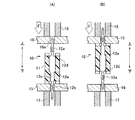
このプレスフィットコンタクトを具えたコネクタは、プレスフィット部をプリント基板のスルーホールに挿入し、コンタクト部は他のコネクタのコンタクトと接触させている。よって、この場合は、プレスフィットコンタクト用コネクタは、プリント基板と他のコネクタとの電気的接続の仲介をしていることになる。これに対して、図6に示す従来例は、絶縁ハウジング11に固着されたプレスフィットコンタクト12に、プレスフィット部12a,12bがその両端に設けられ、そこにプリント基板がそれぞれ実装される、基板−基板用の両端プレスフィット用コネクタ10である。
前記両端プレスフィット用コネクタ10には、図6(A)に示すように、絶縁ハウジング11の上下面に、圧入方向の極性を示す、上面の突起13と下面の突起14とが突設されている。図6(B)に示すように、プレスフィットコンタクト12を絶縁ハウジング11に圧入して固着するには、プレスフィット部12a側の肩部12dを圧入ジグで図示する矢印の方向に押圧する。これは、絶縁ハウジング11との係合を図る係合部12cが、コンタクトの長手方向において片側にしかないからである。
As shown in FIG. 6A, the both-end press-
そこで、この両端プレスフィット用コネクタ10により、プリント基板に実装させる場合には、図7、図8に示すように、最初に、プリント基板15を下受けジグ17に載置して、前記コネクタ10において係合部12cがある側のプレスフィット部12bを前記プリント基板15に圧入する。それには、プリント基板15のスルーホール15aに前記プレスフィット部12bを各々位置合わせして、図9に示すように、打込みジグ18で肩部12dを押圧することで、プレスフィットコンタクト12を圧入してプリント基板15に固定する。
Therefore, when the both-end press-
次に、図10(A)に示すように、上側のプレスフィット部12aにプリント基板16のスルーホール16aを位置合わせして載せ、打込みジグ18により前記プレスフィット部12aにプリント基板16を圧入する。前記打込みジグ18の押圧により、スルーホール16aとプレスフィット部12aとの摺接による摩擦で、プレスフィットコンタクト12が下方向に押されるが、絶縁ハウジング11の段部に肩部12eが衝突して、この絶縁ハウジング11からプレスフィットコンタクト12が抜け出ることがない。
Next, as shown in FIG. 10A, the
また、図10(B)に示すように、絶縁ハウジング11とプリント基板15とを、図9にて示した方法により固定した状態からこれを上下逆にして、下受けジグ17に載置したプリント基板16に、打込みジグ18によって押圧する場合もある。この場合も、プレスフィットコンタクト12は、絶縁ハウジング11の段部に肩部12eが押し付けられる関係にあるので、プレスフィットコンタクト12が抜け落ちることがない。
10B, the
しかし、図11に示すように、最初に、プレスフィットコンタクト12のプレスフィット部12a、即ち、係合部12cが無い側のプレスフィット12aを受けジグ17に載置したプリント基板15のスルーホール15aに、打込みジグ18で絶縁ハウジング11の段部を介して肩部12eを押圧することにより、圧入した場合には、不都合が生じる。
However, as shown in FIG. 11, first, a press-
それは、図12(A)に示すように、受けジグ17に前記プリント基板15と両端プレスフィット用コネクタ10を載置した場合に、プレスフィット部12bにプリント基板16のスルーホール16aを各々位置合わせして、打込みジグ18で当該プリント基板16を下に押圧すると、プレスフィットコンタクト12が絶縁ハウジング11から抜け出してしまう。前記スルーホール16aとの摺接する摩擦で、両端プレスフィット用コネクタ10が下方向に押されても、これを支えるものがないからである。
As shown in FIG. 12 (A), when the printed
また、図12(B)に示す場合にも、前記図12(A)を上下逆にしただけなので、前述と同様に、プレスフィットコンタクト12が絶縁ハウジング11から抜け出てしまう。打込みジグ18は、直接、両端プレスフィット用コネクタ10の肩部12dを押圧することができず、プリント基板15と絶縁ハウジング11とを介して当該両端プレスフィット用コネクタ10を押圧することになるからである。
Also, in the case shown in FIG. 12B, the press-
このように、従来例に係る両端プレスフィット用コネクタ10では、最初にプレスフィットコンタクト12における係合部12cがある側のプレスフィット12bに、プリント基板15を圧入しないと、コネクタ10の絶縁ハウジング11からの抜けが生じてしまうのである。よって、そのような不都合が生じないように、前記コネクタ10には、図6に示すように、極性を示す突起13、突起14が必要となるのである。そして、前記ジグ17,18にも、前記極性用の突起13,14に対応した逃げ孔が必要となる。
As described above, in the
本発明に係る両端プレスフィット用コネクタは、前述のような極性用の突起を不要とし、プリント基板を圧入する際の圧入の手順を前後させても不都合が生じないようにするために提案されたものである。 The double-sided press-fit connector according to the present invention has been proposed in order to eliminate the need for the above-mentioned polarity projections and to prevent inconvenience even if the press-fitting procedure for press-fitting a printed circuit board is followed. Is.
本発明に係る両端プレスフィット用コネクタの上記課題を解決して目的を達成するための要旨は、両端部にプレスフィット部が形成され中央部に導出部が形成され、当該導出部とプレスフィット部との間に係合部が形成されてなるプレスフィットコンタクトを、前記両端部のプレスフィット部を外部に露出させて絶縁ハウジングの固定孔に具えてなるプレスフィットコンタクト用コネクタであって、前記導出部または前記係合部には、前記プレスフィットコンタクトがその長手方向に抜け出ないようにする抜止め防止手段が設けられて、前記絶縁ハウジングに埋設されていることである。
また、前記絶縁ハウジングは、プレスフィットコンタクトの略中央部を境にして、当該プレスフィットコンタクトの長手方向において前後に2分割され、その2分割された各分割体に設けられた固定孔に、前記プレスフィットコンタクトが圧入により挿着され、前記2分割体により前記プレスフィットコンタクトが長手方向の両側から挟装されていることを含むものである。
The gist for solving the above-mentioned problems of the double-end press-fit connector according to the present invention to achieve the object is to form a press-fit portion at both end portions and a lead-out portion at the central portion, and the lead-out portion and the press-fit portion. A press-fit contact connector comprising a press-fit contact having an engaging portion formed between and a press-fit contact formed at a fixed hole of an insulating housing by exposing the press-fit portions at both ends to the outside. The engagement portion is provided with a retaining means for preventing the press-fit contact from coming out in the longitudinal direction, and is embedded in the insulating housing.
Further, the insulating housing is divided into two in the longitudinal direction of the press-fit contact in the longitudinal direction of the press-fit contact in the longitudinal direction of the press-fit contact, The press-fit contact is inserted by press-fitting, and the press-fit contact is sandwiched from both sides in the longitudinal direction by the two-part body.
本発明の両端プレスフィット用コネクタによれば、コンタクトの長手方向の両端側にあるプレスフィット部のうち、いずれかのプレスフィット部にプリント基板を先に圧入して挿着しても、当該コネクタの絶縁ハウジングとプレスフィットコンタクトとの関係において、抜止め防止手段によりコンタクトの抜け落ち等の障害が生じないものである。よって、圧入の作業手順を示す極性用突起を絶縁ハウジングに設ける必要が無くなり、圧入用のジグにも、これに対応した逃げ孔を設ける必要が無くなるので、製作コストの低減となる。更に、前記コネクタにプリント基板を挿着する際に、作業者において圧入方向に注意する必要が無くなって、圧入作業の能率が向上し、打ち込み工数の削減となる。
このような、プレスフィットコンタクト用コネクタを実現する上で、絶縁ハウジングを2分割体にして、これによりプレスフィットコンタクトにその長手方向の両側から前記2分割体を圧入することで、抜止め防止手段を絶縁ハウジング内に埋設することができる。
According to the both-end press-fit connector of the present invention, even if the printed circuit board is first press-fitted into one of the press-fit portions on the both ends in the longitudinal direction of the contact and inserted, the connector In the relationship between the insulating housing and the press-fit contact, the prevention means does not cause a failure such as dropout of the contact. Therefore, it is not necessary to provide the projection for polarity indicating the press-fitting work procedure in the insulating housing, and it is not necessary to provide a corresponding relief hole in the press-fitting jig, thereby reducing the manufacturing cost. Furthermore, when inserting the printed circuit board into the connector, the operator does not need to pay attention to the press-fitting direction, so that the press-fitting work efficiency is improved and the man-hours for driving are reduced.
In realizing such a connector for press-fit contact, the insulating housing is divided into two parts, and thereby, the two-parts are press-fitted into the press-fit contact from both sides in the longitudinal direction, thereby preventing the retaining. Can be embedded in an insulating housing.
本発明に係る両端プレスフィット用コネクタ1は、図1(A),(B)に示すように、コンタクトにおける長手方向の両端部にプレスフィット部2,3が形成され先端側には導入部8,9があり、このコンタクトの中央部に導出部4が形成されている。
As shown in FIGS. 1A and 1B, the double-end press-
前記導出部4とプレスフィット部2,3との間に係合部5,5が形成されてなるプレスフィットコンタクト6を、絶縁ハウジング7の固定孔に具えてなる両端プレスフィット用コネクタ1である。前記プレスフィットコンタクト6の略中央部にある前記導出部4を境にして、前記プレスフィットコンタクト6の長手方向における前後に、絶縁ハウジング7が2分割されているのである。
It is a double-end press-
前記プレスフィットコンタクト6は、薄い金属平板から金型で打ち抜かれて形成されるものである。前記絶縁ハウジング7は、絶縁性の合成樹脂製であり、前記絶縁ハウジング7の分割体7a,7bは、対称形または同一に形成されている。その2分割された各分割体7a,7bに、前記プレスフィットコンタクト6が圧入により、固定孔7cに挿着され挟装されているのである。
The press-
前記プレスフィット部2,3は、ミシン針のように、拡張部があって、その形状に沿ったスリットがある。前記導出部4は、図示する一実施例では、矩形状であり係合部5よりも幅広くされ、肩部4aが形成されている。この肩部4aが、この一実施例において、プレスフィットコンタクト6の抜止め防止手段となっている。
The press-
前記係合部5は、複数個の突起があって、圧入装着されると、その圧入方向と逆方向には突起のひっかかりにより、抜け出ないようになっている。この係合部5における突起も、図1(B)に示すように、プレスフィットコンタクト6の長手方向である上下方向において、分割体7aまたは分割体7bを動かないように固定して、プレスフィットコンタクト6に上から下に力を加えると、上側の係合部5の突起が抵抗し、プレスフィットコンタクト6に下から上に力を加えると、下側の係合部5の突起が抵抗する。よって、絶縁ハウジング7からプレスフィットコンタクト6が抜け出るのを阻止するので、これも、プレスフィットコンタクト6における抜止め防止手段といえる。
The
このように、前記抜止め防止手段は、導出部4における肩部4aであり、前記係合部5の突起でもある。また、例えば、前記導出部4を、前記係合部5の幅よりも細い幅にすれば、その幅の変化する部分において、段部が生じるので、この段部もプレスフィットコンタクト6の抜止め防止手段となる。プレスフィットコンタクト6において、前記導出部4又は係合部5において、抜止め防止手段が存在するれば良いのである。
As described above, the retaining prevention means is the
抜止め防止手段の他の実施例として、例えば、2分割体7a,7bが、前記長手方向に動かないようにするロック手段を有すれば、プレスフィットコンタクト6における前記抜止め防止手段は、一箇所に在ればよいので、前記導出部と係合部5とは、いずれか一つが在れば良くなる。
As another example of the retaining prevention means, for example, if the two-divided
更に、絶縁ハウジング7を、例えば、プレスフィットコンタクト6を金型にインサートして、一体成形することも本発明に係る両端プレスフィット用コネクタ1の他の実施例として含むものである。この場合には、プレスフィットコンタクト6と2分割体7a,7bとの圧入による組立工程は不要となる。
Further, the insulating
上記両端プレスフィット用コネクタ1によって、プリント基板15,16に圧入して実装する手順について説明する。プレスフィットコンタクト6に分割体7a,7bを圧入して両端プレスフィット用コネクタ1を組み立てる。その後、図2に示すように、受けジグ17aにプリント基板15を載置して、両端プレスフィット用コネクタ1のプレスフィットコンタクト6のプレスフィット部9を、前記プリント基板15のスルーホール15aに位置合わせして、打込みジグ18aで両端プレスフィット用コネクタ1を下方向に圧入する。
A procedure for press-fitting and mounting on the printed
ここで、前記受けジグ17aには、極性用の突起を避ける逃げ孔が無く、同様に、打込みジグ18aにも、極性用の突起を避ける逃げ孔が設けられていない。従来例におけるジグ17,18と異なるところであって、ジグ製作の工程において孔加工が不要となる。
Here, the receiving
前記打込みジグ18aは、両端プレスフィット用コネクタ1の絶縁ハウジング7の上端面を押し込んでいる。そして、その押圧力が絶縁ハウジング7から肩部4aを介してプレスフィットコンタクト6に伝達され、プレスフィット部3がスルーホール15aに挿着される。
The driving
次に、図3(A)に示すように、プリント基板16を、そのスルーホール16aと導入部8との位置合わせをして、打込みジグ18aで下方向に押圧してプレスフィットコンタクト6に圧入する。このプレスフィットコンタクト6は、前記スルーホール16aとの摺接による摩擦力で下方向に押されるが、このプレスフィットコンタクト6の肩部4bが分割体7bによって反力を受けるので、絶縁ハウジング7から抜け出ることがない。こうして、両端プレスフィット用コネクタ1の長手方向の両側にプリント基板15,16が実装される。
Next, as shown in FIG. 3A, the printed
また、図3(B)に示すように、両端プレスフィット用コネクタ1とこれに挿着したプリント基板15とを前記打込みジグ18a側にして、受けジグ17a側にプリント基板16を載置して、図3(A)に示す状態と逆にして挿着した場合も同様である。即ち、打込みジグ18aがプリント基板15を介して絶縁ハウジング7を押す。この絶縁ハウジング7の上側の分割体7bが、プレスフィットコンタクト6の肩部4bを押す。これにより、プレスフィットコンタクト6のプレスフィット部2がプリント基板16のスルーホール16aに圧入され、両端プレスフィット用コネクタ1にプリント基板15,16が実装されることになる。
Further, as shown in FIG. 3 (B), the press-
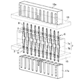
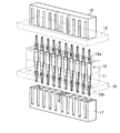
図4と図5とは、前記両端プレスフィット用コネクタ1にプリント基板15,16を圧入して実装させる場合の斜視図と断面図とを示すものである。前記両端プレスフィット用コネクタ1の上下方向における、プレスフィット部2,3のうち、そのどちらを先にプリント基板を圧入しなければならないか、という作業順序を決める必要が無く、両端プレスフィット用コネクタ1が図示した状態と上下逆であっても良い。よって、作業者は、両端プレスフィット用コネクタ1の圧入時の極性を全く気にすることなく、プリント基板15,16の圧入作業を行うことができる。
FIGS. 4 and 5 show a perspective view and a cross-sectional view when the printed
1 両端プレスフィット用コネクタ、
2 プレスフィット部、
3 プレスフィット部、
4 導出部、 4a 肩部、
4b 肩部、
5 係合部、
6 プレスフィットコンタクト、
7 絶縁ハウジング、
7a 分割体、 7b 分割体、
7c 固定孔、
8 導入部、
9 導入部、
10 従来例に係る両端プレスフィット用コネクタ、
15 プリント基板、
16 プリント基板、
17,17a 受けジグ、
18,18a 打込みジグ。
1 Double-end press-fit connector,
2 Press-fit section,
3 Press-fit section,
4 lead-out part, 4a shoulder part,
4b shoulder,
5 engaging part,
6 Press-fit contact,
7 Insulating housing,
7a divided body, 7b divided body,
7c fixing hole,
8 Introduction part,
9 Introduction,
10 Connector for both ends press-fit according to a conventional example,
15 Printed circuit board,
16 Printed circuit board,
17, 17a receiving jig,
18, 18a Driving jig.
Claims (2)
前記導出部または前記係合部には、前記プレスフィットコンタクトがその長手方向に抜け出ないようにする抜止め防止手段が設けられて、前記絶縁ハウジングに埋設されていること、
を特徴とする両端プレスフィット用コネクタ。 A press-fit contact having a press-fit portion formed at both ends and a lead-out portion formed at the center, and an engagement portion formed between the lead-out portion and the press-fit portion, A press-fit contact connector that is exposed to the outside and provided in the fixing hole of the insulating housing,
The lead-out part or the engaging part is provided with a prevention means for preventing the press-fit contact from coming out in the longitudinal direction, and is embedded in the insulating housing.
Features both-end press-fit connector.
を特徴とする請求項1に記載の両端プレスフィット用コネクタ。 The insulating housing is divided into two in the longitudinal direction of the press-fit contact in the longitudinal direction of the press-fit contact, and the press-fit contact is provided in a fixed hole provided in each of the divided parts. Is inserted by press-fitting, and the press-fit contact is sandwiched from both sides in the longitudinal direction by the two-part body,
The connector for press-fitting at both ends according to claim 1.
Priority Applications (3)
| Application Number | Priority Date | Filing Date | Title |
|---|---|---|---|
| JP2006229056A JP4744397B2 (en) | 2006-08-25 | 2006-08-25 | Connector for press-fit at both ends |
| DE102007037839A DE102007037839A1 (en) | 2006-08-25 | 2007-08-10 | Two sided press-in connector has isolated housing, in which number of fixing holes are arranged for insertion of contacts, and number of press-in contacts are inserted in fixing holes |
| US11/892,373 US20080050947A1 (en) | 2006-08-25 | 2007-08-22 | Double-ended press-fit connector |
Applications Claiming Priority (1)
| Application Number | Priority Date | Filing Date | Title |
|---|---|---|---|
| JP2006229056A JP4744397B2 (en) | 2006-08-25 | 2006-08-25 | Connector for press-fit at both ends |
Publications (2)
| Publication Number | Publication Date |
|---|---|
| JP2008053090A JP2008053090A (en) | 2008-03-06 |
| JP4744397B2 true JP4744397B2 (en) | 2011-08-10 |
Family
ID=38973454
Family Applications (1)
| Application Number | Title | Priority Date | Filing Date |
|---|---|---|---|
| JP2006229056A Expired - Fee Related JP4744397B2 (en) | 2006-08-25 | 2006-08-25 | Connector for press-fit at both ends |
Country Status (3)
| Country | Link |
|---|---|
| US (1) | US20080050947A1 (en) |
| JP (1) | JP4744397B2 (en) |
| DE (1) | DE102007037839A1 (en) |
Cited By (2)
| Publication number | Priority date | Publication date | Assignee | Title |
|---|---|---|---|---|
| JP6396545B1 (en) * | 2017-07-12 | 2018-09-26 | イリソ電子工業株式会社 | Board to board connector |
| KR20220170498A (en) | 2021-06-23 | 2022-12-30 | 한국단자공업 주식회사 | Terminal and connector having the same |
Families Citing this family (26)
| Publication number | Priority date | Publication date | Assignee | Title |
|---|---|---|---|---|
| US7254889B1 (en) * | 2000-09-08 | 2007-08-14 | Gabe Cherian | Interconnection devices |
| US20070230142A1 (en) * | 2006-03-29 | 2007-10-04 | Engel John B | Zero parts strain relief |
| DE102006055086B3 (en) * | 2006-11-21 | 2008-06-19 | Tyco Electronics Amp Gmbh | Press-in pin for electrical contacts made of wire material |
| DE102008056923A1 (en) * | 2008-11-12 | 2010-05-27 | Osram Gesellschaft mit beschränkter Haftung | Lighting device with two printed circuit boards |
| DE102009025113A1 (en) * | 2009-06-11 | 2010-12-16 | Continental Teves Ag & Co. Ohg | Press-in contact for connecting an electronic component to a printed circuit board and press-fit tool |
| CN103370994A (en) * | 2011-02-25 | 2013-10-23 | 瑞典爱立信有限公司 | Method for mounting connection pins in component carrier, mold tool for mounting connection pins, component carrier for modules forming electronic assemblies and such assembly |
| JP5360271B1 (en) * | 2012-07-10 | 2013-12-04 | 第一精工株式会社 | Electrical connector |
| US10193292B2 (en) * | 2012-11-30 | 2019-01-29 | J.S.T. Mfg. Co., Ltd. | Jig and press-fitting device comprising this jig |
| DE102013009556A1 (en) * | 2013-06-06 | 2014-12-11 | Valeo Schalter Und Sensoren Gmbh | Driver assistance device for a motor vehicle and method for producing such |
| JP5704196B2 (en) * | 2013-07-05 | 2015-04-22 | 第一精工株式会社 | Connector terminals and electrical connectors |
| JP5655914B1 (en) * | 2013-08-30 | 2015-01-21 | 第一精工株式会社 | Electrical connector housing, electrical connector, and connector terminal mounting method |
| JP6256675B2 (en) * | 2013-08-30 | 2018-01-10 | 矢崎総業株式会社 | Pin header |
| US9960508B2 (en) | 2014-05-22 | 2018-05-01 | Te Connectivity Corporation | Wire lug connector |
| US9431733B1 (en) * | 2015-02-11 | 2016-08-30 | Dell Products, Lp | Double action compliant connector pin |
| JP6550890B2 (en) * | 2015-04-22 | 2019-07-31 | 住友電装株式会社 | Press-fit terminal |
| FR3038464A1 (en) * | 2015-06-30 | 2017-01-06 | Souriau | METHOD FOR MOUNTING A PRESSURE INSERTED MULTICONTACT CONNECTOR |
| US20170179625A1 (en) * | 2015-12-21 | 2017-06-22 | Kai Xiao | Attachment techniques for printed circuit boards |
| JP6984127B2 (en) * | 2016-12-28 | 2021-12-17 | 富士電機株式会社 | Semiconductor devices and methods for manufacturing semiconductor devices |
| CN110366876B (en) * | 2017-03-06 | 2023-05-05 | 三菱电机株式会社 | Control unit with press-fit structure |
| JP6604406B2 (en) * | 2018-08-24 | 2019-11-13 | 株式会社デンソー | Power supply |
| US11616330B2 (en) * | 2021-05-26 | 2023-03-28 | Te Connectivity Solutions Gmbh | Power connector assembly |
| US12027792B2 (en) * | 2021-07-28 | 2024-07-02 | Japan Aviation Electronics Industry, Limited | Connector including a contact, an electrical wire, and a sleeve member that accommodates parts of the contact and electrical wire |
| US11839017B2 (en) * | 2021-08-05 | 2023-12-05 | Te Connectivity Solutions Gmbh | Thermal press-fit terminal |
| JP7541050B2 (en) * | 2022-04-28 | 2024-08-27 | 矢崎総業株式会社 | Electronic Component Module |
| JP2025139828A (en) * | 2024-03-13 | 2025-09-29 | 株式会社オートネットワーク技術研究所 | Substrate Device |
| JP2025139826A (en) * | 2024-03-13 | 2025-09-29 | 株式会社オートネットワーク技術研究所 | Substrate Device |
Family Cites Families (7)
| Publication number | Priority date | Publication date | Assignee | Title |
|---|---|---|---|---|
| US4446505A (en) * | 1982-03-22 | 1984-05-01 | Amp Incorporated | Electrical connector for interconnecting printed circuit boards |
| JPS63301473A (en) * | 1987-05-30 | 1988-12-08 | Canon Inc | Connecting terminal |
| DE69208456T2 (en) * | 1992-03-06 | 1996-07-04 | Molex Inc | Connector with press-in pins |
| JP2612530B2 (en) * | 1992-05-18 | 1997-05-21 | 日本航空電子工業株式会社 | connector |
| JP4311859B2 (en) * | 2000-04-17 | 2009-08-12 | 富士通株式会社 | Backboard |
| US6623280B2 (en) * | 2001-11-13 | 2003-09-23 | International Business Machines Corporation | Dual compliant pin interconnect system |
| US7220151B2 (en) * | 2004-05-25 | 2007-05-22 | International Business Machines Corporation | Power connector |
-
2006
- 2006-08-25 JP JP2006229056A patent/JP4744397B2/en not_active Expired - Fee Related
-
2007
- 2007-08-10 DE DE102007037839A patent/DE102007037839A1/en not_active Withdrawn
- 2007-08-22 US US11/892,373 patent/US20080050947A1/en not_active Abandoned
Cited By (2)
| Publication number | Priority date | Publication date | Assignee | Title |
|---|---|---|---|---|
| JP6396545B1 (en) * | 2017-07-12 | 2018-09-26 | イリソ電子工業株式会社 | Board to board connector |
| KR20220170498A (en) | 2021-06-23 | 2022-12-30 | 한국단자공업 주식회사 | Terminal and connector having the same |
Also Published As
| Publication number | Publication date |
|---|---|
| JP2008053090A (en) | 2008-03-06 |
| DE102007037839A1 (en) | 2008-02-28 |
| US20080050947A1 (en) | 2008-02-28 |
Similar Documents
| Publication | Publication Date | Title |
|---|---|---|
| JP4744397B2 (en) | Connector for press-fit at both ends | |
| JP4526428B2 (en) | Board to board connector | |
| JP4592462B2 (en) | Board connector | |
| JP5947679B2 (en) | Board connector | |
| JP4506456B2 (en) | Board terminal mounting structure on circuit board | |
| JP5912632B2 (en) | connector | |
| EP2091106B1 (en) | Retaining member, electric component and electric device | |
| JP4586745B2 (en) | Terminal mounting structure on board | |
| JP2009277489A (en) | Socket for electronic part installation | |
| JP2000182694A (en) | Board connection connector | |
| JP5203099B2 (en) | Vertical SMT connector | |
| JP2009151940A (en) | Terminal press-fit structure and electric connector | |
| JP4846431B2 (en) | Board connector | |
| KR101625691B1 (en) | Electric connector for circuit substrate | |
| JP2006031944A (en) | Surface mounting connector | |
| JP2010153080A (en) | Terminal for electrical connection and connector using the same | |
| CN110233370B (en) | Terminals, connectors and connector assemblies | |
| JP6153207B2 (en) | Jig and press-fitting device provided with this jig | |
| JP6986380B2 (en) | Connector mounting structure and connector shield | |
| JP2007048684A (en) | connector | |
| JP2008004400A (en) | Connector | |
| JP2012134086A (en) | Electric connection box | |
| JP5888811B2 (en) | Busbar assembly structure | |
| JP4506712B2 (en) | connector | |
| JP2774394B2 (en) | Receptacle connector using flexible wiring board |
Legal Events
| Date | Code | Title | Description |
|---|---|---|---|
| A621 | Written request for application examination |
Free format text: JAPANESE INTERMEDIATE CODE: A621 Effective date: 20090710 |
|
| A977 | Report on retrieval |
Free format text: JAPANESE INTERMEDIATE CODE: A971007 Effective date: 20110408 |
|
| A01 | Written decision to grant a patent or to grant a registration (utility model) |
Free format text: JAPANESE INTERMEDIATE CODE: A01 Effective date: 20110419 |
|
| A01 | Written decision to grant a patent or to grant a registration (utility model) |
Free format text: JAPANESE INTERMEDIATE CODE: A01 |
|
| A61 | First payment of annual fees (during grant procedure) |
Free format text: JAPANESE INTERMEDIATE CODE: A61 Effective date: 20110510 |
|
| FPAY | Renewal fee payment (event date is renewal date of database) |
Free format text: PAYMENT UNTIL: 20140520 Year of fee payment: 3 |
|
| R150 | Certificate of patent or registration of utility model |
Free format text: JAPANESE INTERMEDIATE CODE: R150 |
|
| R250 | Receipt of annual fees |
Free format text: JAPANESE INTERMEDIATE CODE: R250 |
|
| S531 | Written request for registration of change of domicile |
Free format text: JAPANESE INTERMEDIATE CODE: R313531 |
|
| R350 | Written notification of registration of transfer |
Free format text: JAPANESE INTERMEDIATE CODE: R350 |
|
| LAPS | Cancellation because of no payment of annual fees |