JP4741495B2 - Incremental redundancy transmission in MIMO communication systems - Google Patents
Incremental redundancy transmission in MIMO communication systems Download PDFInfo
- Publication number
- JP4741495B2 JP4741495B2 JP2006526329A JP2006526329A JP4741495B2 JP 4741495 B2 JP4741495 B2 JP 4741495B2 JP 2006526329 A JP2006526329 A JP 2006526329A JP 2006526329 A JP2006526329 A JP 2006526329A JP 4741495 B2 JP4741495 B2 JP 4741495B2
- Authority
- JP
- Japan
- Prior art keywords
- data
- symbol
- packet
- block
- data packet
- Prior art date
- Legal status (The legal status is an assumption and is not a legal conclusion. Google has not performed a legal analysis and makes no representation as to the accuracy of the status listed.)
- Active
Links
Images


Classifications
-
- H—ELECTRICITY
- H04—ELECTRIC COMMUNICATION TECHNIQUE
- H04L—TRANSMISSION OF DIGITAL INFORMATION, e.g. TELEGRAPHIC COMMUNICATION
- H04L1/00—Arrangements for detecting or preventing errors in the information received
- H04L1/12—Arrangements for detecting or preventing errors in the information received by using return channel
- H04L1/16—Arrangements for detecting or preventing errors in the information received by using return channel in which the return channel carries supervisory signals, e.g. repetition request signals
- H04L1/18—Automatic repetition systems, e.g. Van Duuren systems
- H04L1/1812—Hybrid protocols; Hybrid automatic repeat request [HARQ]
- H04L1/1819—Hybrid protocols; Hybrid automatic repeat request [HARQ] with retransmission of additional or different redundancy
-
- H—ELECTRICITY
- H04—ELECTRIC COMMUNICATION TECHNIQUE
- H04B—TRANSMISSION
- H04B7/00—Radio transmission systems, i.e. using radiation field
- H04B7/02—Diversity systems; Multi-antenna system, i.e. transmission or reception using multiple antennas
- H04B7/04—Diversity systems; Multi-antenna system, i.e. transmission or reception using multiple antennas using two or more spaced independent antennas
- H04B7/0413—MIMO systems
- H04B7/0417—Feedback systems
-
- H—ELECTRICITY
- H03—ELECTRONIC CIRCUITRY
- H03M—CODING; DECODING; CODE CONVERSION IN GENERAL
- H03M13/00—Coding, decoding or code conversion, for error detection or error correction; Coding theory basic assumptions; Coding bounds; Error probability evaluation methods; Channel models; Simulation or testing of codes
- H03M13/33—Synchronisation based on error coding or decoding
-
- H—ELECTRICITY
- H04—ELECTRIC COMMUNICATION TECHNIQUE
- H04B—TRANSMISSION
- H04B7/00—Radio transmission systems, i.e. using radiation field
- H04B7/02—Diversity systems; Multi-antenna system, i.e. transmission or reception using multiple antennas
- H04B7/04—Diversity systems; Multi-antenna system, i.e. transmission or reception using multiple antennas using two or more spaced independent antennas
- H04B7/06—Diversity systems; Multi-antenna system, i.e. transmission or reception using multiple antennas using two or more spaced independent antennas at the transmitting station
- H04B7/0613—Diversity systems; Multi-antenna system, i.e. transmission or reception using multiple antennas using two or more spaced independent antennas at the transmitting station using simultaneous transmission
- H04B7/0615—Diversity systems; Multi-antenna system, i.e. transmission or reception using multiple antennas using two or more spaced independent antennas at the transmitting station using simultaneous transmission of weighted versions of same signal
- H04B7/0619—Diversity systems; Multi-antenna system, i.e. transmission or reception using multiple antennas using two or more spaced independent antennas at the transmitting station using simultaneous transmission of weighted versions of same signal using feedback from receiving side
- H04B7/0621—Feedback content
- H04B7/0623—Auxiliary parameters, e.g. power control [PCB] or not acknowledged commands [NACK], used as feedback information
-
- H—ELECTRICITY
- H04—ELECTRIC COMMUNICATION TECHNIQUE
- H04L—TRANSMISSION OF DIGITAL INFORMATION, e.g. TELEGRAPHIC COMMUNICATION
- H04L1/00—Arrangements for detecting or preventing errors in the information received
- H04L1/004—Arrangements for detecting or preventing errors in the information received by using forward error control
- H04L1/0045—Arrangements at the receiver end
- H04L1/0047—Decoding adapted to other signal detection operation
- H04L1/0048—Decoding adapted to other signal detection operation in conjunction with detection of multiuser or interfering signals, e.g. iteration between CDMA or MIMO detector and FEC decoder
-
- H—ELECTRICITY
- H04—ELECTRIC COMMUNICATION TECHNIQUE
- H04L—TRANSMISSION OF DIGITAL INFORMATION, e.g. TELEGRAPHIC COMMUNICATION
- H04L1/00—Arrangements for detecting or preventing errors in the information received
- H04L1/004—Arrangements for detecting or preventing errors in the information received by using forward error control
- H04L1/0045—Arrangements at the receiver end
- H04L1/0047—Decoding adapted to other signal detection operation
- H04L1/005—Iterative decoding, including iteration between signal detection and decoding operation
-
- H—ELECTRICITY
- H04—ELECTRIC COMMUNICATION TECHNIQUE
- H04L—TRANSMISSION OF DIGITAL INFORMATION, e.g. TELEGRAPHIC COMMUNICATION
- H04L1/00—Arrangements for detecting or preventing errors in the information received
- H04L1/004—Arrangements for detecting or preventing errors in the information received by using forward error control
- H04L1/0056—Systems characterized by the type of code used
- H04L1/0071—Use of interleaving
-
- H—ELECTRICITY
- H04—ELECTRIC COMMUNICATION TECHNIQUE
- H04L—TRANSMISSION OF DIGITAL INFORMATION, e.g. TELEGRAPHIC COMMUNICATION
- H04L1/00—Arrangements for detecting or preventing errors in the information received
- H04L1/0001—Systems modifying transmission characteristics according to link quality, e.g. power backoff
- H04L1/0002—Systems modifying transmission characteristics according to link quality, e.g. power backoff by adapting the transmission rate
- H04L1/0003—Systems modifying transmission characteristics according to link quality, e.g. power backoff by adapting the transmission rate by switching between different modulation schemes
-
- H—ELECTRICITY
- H04—ELECTRIC COMMUNICATION TECHNIQUE
- H04L—TRANSMISSION OF DIGITAL INFORMATION, e.g. TELEGRAPHIC COMMUNICATION
- H04L1/00—Arrangements for detecting or preventing errors in the information received
- H04L1/0001—Systems modifying transmission characteristics according to link quality, e.g. power backoff
- H04L1/0009—Systems modifying transmission characteristics according to link quality, e.g. power backoff by adapting the channel coding
-
- H—ELECTRICITY
- H04—ELECTRIC COMMUNICATION TECHNIQUE
- H04L—TRANSMISSION OF DIGITAL INFORMATION, e.g. TELEGRAPHIC COMMUNICATION
- H04L1/00—Arrangements for detecting or preventing errors in the information received
- H04L1/02—Arrangements for detecting or preventing errors in the information received by diversity reception
- H04L1/06—Arrangements for detecting or preventing errors in the information received by diversity reception using space diversity
- H04L1/0618—Space-time coding
-
- H—ELECTRICITY
- H04—ELECTRIC COMMUNICATION TECHNIQUE
- H04L—TRANSMISSION OF DIGITAL INFORMATION, e.g. TELEGRAPHIC COMMUNICATION
- H04L1/00—Arrangements for detecting or preventing errors in the information received
- H04L1/12—Arrangements for detecting or preventing errors in the information received by using return channel
- H04L1/16—Arrangements for detecting or preventing errors in the information received by using return channel in which the return channel carries supervisory signals, e.g. repetition request signals
- H04L1/1607—Details of the supervisory signal
- H04L1/1671—Details of the supervisory signal the supervisory signal being transmitted together with control information
-
- H—ELECTRICITY
- H04—ELECTRIC COMMUNICATION TECHNIQUE
- H04L—TRANSMISSION OF DIGITAL INFORMATION, e.g. TELEGRAPHIC COMMUNICATION
- H04L27/00—Modulated-carrier systems
- H04L27/26—Systems using multi-frequency codes
- H04L27/2601—Multicarrier modulation systems
- H04L27/2626—Arrangements specific to the transmitter only
-
- H—ELECTRICITY
- H04—ELECTRIC COMMUNICATION TECHNIQUE
- H04L—TRANSMISSION OF DIGITAL INFORMATION, e.g. TELEGRAPHIC COMMUNICATION
- H04L27/00—Modulated-carrier systems
- H04L27/26—Systems using multi-frequency codes
- H04L27/2601—Multicarrier modulation systems
- H04L27/2647—Arrangements specific to the receiver only
-
- H—ELECTRICITY
- H04—ELECTRIC COMMUNICATION TECHNIQUE
- H04L—TRANSMISSION OF DIGITAL INFORMATION, e.g. TELEGRAPHIC COMMUNICATION
- H04L5/00—Arrangements affording multiple use of the transmission path
- H04L5/0001—Arrangements for dividing the transmission path
- H04L5/0014—Three-dimensional division
- H04L5/0023—Time-frequency-space
-
- H—ELECTRICITY
- H04—ELECTRIC COMMUNICATION TECHNIQUE
- H04L—TRANSMISSION OF DIGITAL INFORMATION, e.g. TELEGRAPHIC COMMUNICATION
- H04L5/00—Arrangements affording multiple use of the transmission path
- H04L5/003—Arrangements for allocating sub-channels of the transmission path
- H04L5/0048—Allocation of pilot signals, i.e. of signals known to the receiver
Landscapes
- Engineering & Computer Science (AREA)
- Computer Networks & Wireless Communication (AREA)
- Signal Processing (AREA)
- Physics & Mathematics (AREA)
- Probability & Statistics with Applications (AREA)
- Theoretical Computer Science (AREA)
- Quality & Reliability (AREA)
- Radio Transmission System (AREA)
- Mobile Radio Communication Systems (AREA)
- Detection And Prevention Of Errors In Transmission (AREA)
- Small-Scale Networks (AREA)
Abstract
Description
35U.S.C.119に基づく優先権の主張
本出願は、参照することによりその全体が組み込まれる、2003年9月9日に出願された米国仮出願シリアル番号第60/501,777および2003年12月19日に出願された米国仮出願シリアル番号第60/531,391の優先権を主張する。
35U. S. C. Priority claim based on 119 This application is incorporated by reference in its entirety, US Provisional Application Serial Nos. 60 / 501,777 filed September 9, 2003, and December 19, 2003. Claims priority of filed US provisional application serial number 60 / 531,391.
この発明は一般に、通信に関し、特に、多重入力多重出力(MIMO)通信システムにおいてデータを送信するための技術に関する。 The present invention relates generally to communication, and more particularly to techniques for transmitting data in a multiple-input multiple-output (MIMO) communication system.
MIMOシステムはデータ送信のために複数の(NT)送信アンテナおよび複数の(NR)受信アンテナを使用し、(NT、NR)システムとして表示される。NT送信およびNR受信アンテナによって形成されたMIMOチャネルは、NSの空間チャネルに分解してもよい。但し、Ns≦min{NT,NR)である。NSの空間チャネルが複数の送信および受信アンテナにより作られ、受信アンテナがデータ送信のために使用されるなら、MIMOシステムは、増加した送信能力を提供することができる。 A MIMO system uses multiple (NT) transmit antennas and multiple (NR) receive antennas for data transmission and is denoted as an (N T , N R ) system. A MIMO channel formed by the NT transmit and NR receive antennas may be decomposed into spatial channels N S. However, Ns ≦ min {N T , N R ). If N S spatial channels are created by multiple transmit and receive antennas and the receive antennas are used for data transmission, the MIMO system can provide increased transmission capability.
MIMOシステムでの主な課題は、チャネル条件に基づいてデータ送信のための適切なレートを選択することである。「レート」は、特定のデータレートまたは情報ビットレート、特定のコーディングスキーム、特定の変調スキーム、特定のデータパケットサイズ等を示してもよい。レート選択の目的は、特定のパケットエラーレート(例えば、1%PER)により定量化してもよい、ある品質目標を満足しながら、NSの空間チャネル上のスループットを最大化することである。 The main challenge in a MIMO system is to select an appropriate rate for data transmission based on channel conditions. “Rate” may indicate a specific data rate or information bit rate, a specific coding scheme, a specific modulation scheme, a specific data packet size, and so on. The purpose of rate selection is to maximize throughput on the NS spatial channel while meeting certain quality goals that may be quantified by a specific packet error rate (eg, 1% PER).
MIMOチャネルの送信容量は、NSの空間チャネルにより得られる信号対雑音および干渉比(SNRs)に依存する。SNRは、チャネル条件に順番に依存する。1つの一般的なMIMOシステムにおいて、送信機は、静的MIMOチャネルのモデルに基づいて選択されるレートに従ってデータを符号化し、変調し、送信する。モデルが正確であり、かつMIMOチャネルが相対的に静的(すなわち、時間に対して変化しない)なら、良好な性能を得ることができる。他の従来のMIMOシステムにおいて、受信機はMIMOチャネルを推定し、チャネル推定に基づいた適切なレートを選択し、送信器へ選択されたレートを送る。次に、送信機は選択されたレートに従ってデータを処理し送信する。このシステムの性能は、MIMOチャネルの性質およびチャネル推定の精度に依存する。 Transmission capacity of the MIMO channel is dependent on the signal-to-noise-and-interference ratio obtained by the spatial channels N S (SNRs). SNR depends in turn on channel conditions. In one common MIMO system, a transmitter encodes, modulates, and transmits data according to a rate selected based on a model of a static MIMO channel. Good performance can be obtained if the model is accurate and the MIMO channel is relatively static (ie, does not change over time). In other conventional MIMO systems, the receiver estimates the MIMO channel, selects an appropriate rate based on the channel estimate, and sends the selected rate to the transmitter. The transmitter then processes and transmits the data according to the selected rate. The performance of this system depends on the nature of the MIMO channel and the accuracy of the channel estimation.
上述した両方の従来のMIMOシステムの場合、送信機は典型的にそのデータパケットのために選択されたレートで各データパケットを処理し送信する。受信機は、送信器によって送信された各データパケットをデコードし、パケットが正しくあるいはエラーでデコードされたかどうかを決定する。パケットが正しくデコードされるなら受信機は、アクノレジメント(ACK)を返送してもよく、またはパケットがエラーでデコードされるなら、否定応答(NAK)を返送してもよい。送信器は、そのパケットに対して受信機からNAKを受信すると、その全体において、受信機によりエラーでデコードされた各データパケットを再送信してもよい。 For both conventional MIMO systems described above, the transmitter typically processes and transmits each data packet at the rate selected for that data packet. The receiver decodes each data packet transmitted by the transmitter and determines whether the packet was decoded correctly or in error. The receiver may return an acknowledgment (ACK) if the packet is decoded correctly, or may return a negative acknowledgment (NAK) if the packet is decoded with an error. When the transmitter receives a NAK from the receiver for that packet, the transmitter may retransmit each data packet decoded in error by the receiver in its entirety.
上述した両方のMIMOシステムの性能は、レート選択の精度に高度に依存する。データパケットのための選択されたレートがあまりにも控えめなら(例えば、実際のSNRはSNR推定値よりはるかに良いので)、データパケットを送信するために過度のシステムリソースが消費され、チャネル容量は十分に利用されない。反対に、データパケットのための選択されたレートがあまりにも積極的なら、パケットは受信機によりエラーでデコードされるかもしれず、システムリソースは、データパケットを再送信するために消費されるかもしれない。MIMOシステムのためのレート選択は、(1)MIMOチャネルのためのチャネル推定におけるより大きな複雑さおよび(2)MIMOチャネルの複数の空間チャネルの時間変化する独立した性質のために手腕を問われている。 The performance of both MIMO systems described above is highly dependent on the accuracy of rate selection. If the selected rate for the data packet is too conservative (eg, the actual SNR is much better than the SNR estimate), excessive system resources are consumed to transmit the data packet and the channel capacity is sufficient Not used for. Conversely, if the selected rate for the data packet is too aggressive, the packet may be decoded in error by the receiver and system resources may be consumed to retransmit the data packet . Rate selection for MIMO systems is challenged due to (1) greater complexity in channel estimation for MIMO channels and (2) time-varying independent nature of multiple spatial channels of MIMO channels. Yes.
それゆえ、MIMOシステムにおいてデータを効率的に送信し、良好な性能を得るために正確なレート選択を必要としないための技術のための技術的必要性がある。 Therefore, there is a technical need for techniques for efficiently transmitting data in a MIMO system and not requiring accurate rate selection to obtain good performance.
技術は、MIMOシステムでのインクリメンタルな冗長度(IR)送信を行なうためにここに提供される。最初に、MIMOシステムにおける受信機あるいは送信機はMIMOチャネルを推定し、MIMOチャネル上のデータ送信に適切なレートを選択する。受信機がレート選択を実行するなら、送信機には選択されたレートが供給される。 Techniques are provided here for performing incremental redundancy (IR) transmissions in MIMO systems. Initially, a receiver or transmitter in a MIMO system estimates the MIMO channel and selects an appropriate rate for data transmission on the MIMO channel. If the receiver performs rate selection, the transmitter is provided with the selected rate.
送信機は、選択されたレートに基づいてデータパケットを処理し(例えば、符号化し、分割し、インターリーブし、変調する)、データパケットのための複数(NB)のデータシンボルブロックを得る。第1のデータシンボルブロックは、好ましいチャネル条件下で、受信機がデータパケットをリカバーすることを可能にするために十分な情報を典型的に含む。残りのデータシンボルブロックの各々は、それほど好ましくないチャネル条件下で、受信機がデータパケットをリカバー可能にするためにさらなる冗長度を含む。 The transmitter processes (eg, encodes, splits, interleaves, and modulates) the data packet based on the selected rate to obtain multiple (N B ) data symbol blocks for the data packet. The first data symbol block typically contains sufficient information to allow the receiver to recover the data packet under favorable channel conditions. Each of the remaining data symbol blocks includes additional redundancy to allow the receiver to recover the data packet under less favorable channel conditions.
送信機は、第1のデータシンボルブロックをNTの送信アンテナから受信機におけるNRの受信アンテナに送信する。その後送信機は、データパケットが受信機により正しくリカバーされるまで、またはNBブロックのすべてが送信されるまで、一度に1つのブロックの割合で、NBデータシンボルブロックの残りのブロックを送信する。 The transmitter transmits the first data symbol block from the NT transmit antennas to the NR receive antennas at the receiver. Thereafter the transmitter until the data packet is correctly recovered by the receiver, or until all of the N B blocks are transmitted at a rate of one block at a time, and transmits the remaining blocks of the N B data symbol blocks .
NPのデータパケットのための複数(NP)のデータシンボルブロックがNTの送信アンテナから同時に送信されるなら、送信機は、NPのデータパケットが類似のチャネル条件を経験するようにこれらのNPのデータシンボルブロックをさらに処理する。 If the data symbol blocks of a plurality (N P) for the data packets N P are simultaneously transmitted from transmitting antennas N T, the transmitter, the data packet N P these to experience similar channel conditions N P data symbol blocks are further processed.
これは、MIMOチャネルを介して同時に送信されるすべてのデータパケットに単一のレートが使用されることを可能にする。 This allows a single rate to be used for all data packets transmitted simultaneously over the MIMO channel.
受信機は、送信機により送信される各データシンボルブロックのための受信されたシンボルブロックを得る。受信機は、各受信されたシンボルブロックを「検出」し、対応するデータシンボルブロックの推定値である、検出されたシンボルブロックを得る。 The receiver obtains a received symbol block for each data symbol block transmitted by the transmitter. The receiver “detects” each received symbol block to obtain a detected symbol block that is an estimate of the corresponding data symbol block.
次に、受信機は、データパケットに対して得られるすべての検出されたシンボルブロックを処理し(例えば、復調し、デインターリーブし、再アセンブルし、およびデコードする)、デコードされたパケットを供給する。受信機は、デコードされたパケットが正しくデコードされたならACKを返送してもよく、デコードされたパケットがエラーなら、NAKを返送してもよい。デコードされたパケットがエラーなら、送信機により送信される別のデータシンボルブロックに対して別の受信されたシンボルブロックが得られるとき、受信機は処理を反復する。 The receiver then processes (eg, demodulates, deinterleaves, reassembles, and decodes) all detected symbol blocks obtained for the data packet and provides a decoded packet. . The receiver may return an ACK if the decoded packet is decoded correctly, and may return a NAK if the decoded packet is an error. If the decoded packet is in error, the receiver repeats the process when another received symbol block is obtained for another data symbol block transmitted by the transmitter.
また、受信機は、反復検出およびデコーディング(IDD)スキームを用いてデータパケットをリカバーしてもよい。IDDスキームの場合、データパケットに対して新しい受信されたシンボルブロックが得られるときはいつでも、すべての受信されたシンボルブロックに関して検出とデコーディングが複数(Ndd)回反復的に実行され、デコードされたパケットを得る。検出器はすべての受信されるシンボルブロックに対して検出を実行し、検出されたシンボルブロックを提供する。デコーダーはすべての検出されたシンボルブロックに対してデコーディングを実行し、次の反復において検出器により使用される演繹的情報をデコーダーに供給する。デコードされたパケットは最後の反復のためにデコーダー出力に基づいて生成される。 The receiver may also recover the data packet using an iterative detection and decoding (IDD) scheme. For the IDD scheme, whenever a new received symbol block is obtained for a data packet, detection and decoding are iteratively performed and decoded multiple (N dd ) times for all received symbol blocks. Get the packet. The detector performs detection on all received symbol blocks and provides detected symbol blocks. The decoder performs decoding on all detected symbol blocks and provides a priori information to be used by the detector in the next iteration. A decoded packet is generated based on the decoder output for the last iteration.
この発明の種々の観点および実施形態は、以下にさらに詳細に記載される。 Various aspects and embodiments of the invention are described in further detail below.
本発明の特徴、性質及び利点は、類似による参照文字が相応して、全体で特定する図面と関連して解釈されるときに後述される詳細な説明からさらに明らかになるであろう。 The features, nature and advantages of the present invention will become more apparent from the detailed description set forth below when taken in conjunction with the drawings in which like reference characters accordingly correspond accordingly.
ここで使用される「例示」という用語は、「例、インスタンス、または例証」として機能することを意味する。「例示」としてここに記載される任意の実施形態または設計は、他の実施形態または設計に対して好適である、または利点があるとして必ずしも解釈されるべきでない。 As used herein, the term “exemplary” means functioning as an “example, instance, or illustration”. Any embodiment or design described herein as "exemplary" is not necessarily to be construed as preferred or advantageous over other embodiments or designs.
NSの空間チャネルを有したMIMOシステムの場合、Npのデータパケットは、NTの送信アンテナから同時に送信してもよい。但し、1≦Np≦Nsである。Npの値にかかわらず、単一のレートをすべての同時に送信されたデータパケットに対して使用してもよい。単一レートの使用は、MIMOシステムにおける送信機と受信機の両方における処理を簡単化することができる。 For a MIMO system with N S spatial channels, N p data packets may be transmitted simultaneously from N T transmit antennas. However, 1 ≦ N p ≦ N s . Regardless of the value of N p , a single rate may be used for all simultaneously transmitted data packets. The use of a single rate can simplify processing at both the transmitter and receiver in a MIMO system.
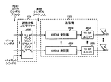
図1は、IR送信を実施するMIMOシステム100における送信機110と受信機150のブロック図を示す。送信機110において、TXデータプロセッサー120は、データソース112からデータパケットを受信する。TXデータプロセッサー120は、そのパケットのために選択されたレートに従って各データパケットを処理し(例えば、フォーマット化し、符号化し、分割し、インターリーブし、および変調する)パケットのためのデータシンボルのNBブロックを得る。但しNB>1であり、選択されたレートに依存していてもよい。各データパケットのための選択されたレートは、コントローラー140により供給される種々の制御により示される、そのパケットのためのデータレート、コーディングスキームまたはコーディングレート、変調スキーム、パケットサイズ、データシンボルブロック数、等を示してもよい。IR送信の場合、各データパケットのためのNBのデータシンボルブロックは、パケットが受信機150により正しくデコードされるまでまたはすべてのNBのデータシンボルブロックが送信されるまで、一度に1つのブロックの割合で送信される。
FIG. 1 shows a block diagram of a
TX空間プロセッサー130は、データシンボルブロックを受信し、1つのタイムスロット(または単に「スロット」)においてNTの送信アンテナから各データシンボルブロックを送信するための必要な処理を実行する。スロットはMIMOシステム100のための所定の時間期間である。以下に記載されるように、TX空間プロセッサー130は、デマルチプレクシング、空間処理等を実行してもよい。スロット毎に、TX空間プロセッサー130は、1つのデータシンボルブロックを処理し、必要に応じてパイロットシンボルに多重化し、送信シンボルのNTのシーケンスを送信機ユニット(TMTR)132に供給する。各送信シンボルはデータシンボルのためであってもよいし、パイロットシンボルのためであってもよい。
TX
送信機ユニット132は、NTの送信シンボルシーケンスを受信して条件付けし(例えば、アナログに変換し、周波数変換し、フィルターし、および増幅する)、NTの変調信号を得る。次に、各変調された信号は、それぞれの(図1に示していない)送信アンテナから送信され、MIMOチャネルを介して受信機150に供給される。MIMOチャネルは、Hのチャネル応答を備えたNTの送信された信号を歪ませ、他の送信器からの付加白色ガウス雑音および恐らく干渉を備えた送信された信号をさらに劣化させる。
A
受信機150において、NTの送信された信号は、(図1に示していない)NRの受信アンテナの各々により受信され、NRの受信アンテナからのNRの受信された信号は、受信機ユニット(RCVR)154に供給される。受信機ユニット154は、各受信信号を条件付けし、デジタル化し、前処理し、スロット毎に受信されたシンボルのシーケンスを得る。受信機ユニット154は、NRの受信された(データのための)シンボルシーケンスをRX空間プロセッサー160に供給し、(パイロットのための)受信されたパイロットシンボルをチャネル推定器172に供給する。RX空間プロセッサー160は、各スロットのためのNRの受信されたシンボルシーケンスを処理し(例えば、検出し多重化する)、検出されたシンボルブロックを得る。これは、そのスロットに対して送信機110により送信されたデータシンボルブロックの推定値である。
At
RXデータプロセッサー170は、リカバーされる(すなわち、「現在の」パケット)データパケットのために受信されたすべての検出されたシンボルブロックを受信し、選択されたレートに従って、これらの検出されたシンボルブロックを処理し(例えば、復調し、デインターリーブし、再アセンブルし、およびデコードする)、および送信機110により送信されるデータパケットの推定値であるデコードされたパケットを供給する。また、RXデータプロセッサー170は、パケットが正しくデコードされたかまたはエラーでデコードされたかを示すデコードされたパケットのステータスを供給する。
The
チャネル推定器172は、受信されたパイロットシンボルおよび/または受信されたデータシンボルを処理し、MIMOチャネルのためのチャネル推定値(例えば、チャネル利得推定値およびSNR推定値)を得る。レートセレクター174はチャネル推定値を受信し、受信機に送信される次のデータパケットのためのレートを選択する。コントローラー180はレートセレクター174から選択されたレートおよびRXデータプロセッサー170からのパケットステータスを受信し、送信機110のためのフィードバック情報をアセンブルする。フィードバック情報は、次のパケットのための選択されたレート、現在のパケットのためのACKまたはNAK等を含んでいてもよい。フィードバック情報は、TXデータ/空間プロセッサー190により処理され、さらに送信機ユニット192により条件付けされ、フィードバックチャネルを介して送信機110に送信される。
送信機110において、受信機150により送信される信号(複数の場合もある)は、受信機ユニット146により受信され条件付けされ、さらにRX空間/データプロセッサー148により処理され、受信機150により送信されたフィードバック情報をリカバーする。コントローラー140は、リカバーされたフィードバック情報を受信し、選択されたレートを使用して受信機150に送信される次のデータパケットを処理し、ACK/NAKを用いて現在のパケットのIR送信を制御する。
At
コントローラー140および180は、それぞれ送信機110および受信機150における動作を指示する。メモリユニット142および182は、それぞれコントローラー140および180によって使用されるプログラムコードおよびデータのための記憶装置を提供する。メモリユニット142および182は、図1に示すようにコントローラー140内部にあってもよいし、これらのコントローラーの外部にあってもよい。図1に示される処理装置は、以下に詳細に記載される。
図2は、MIMOシステムにおいてIR送信を送信しおよび受信するプロセス200のフロー図を示す。最初に、受信機は、送信機から受信したパイロットおよび/またはデータシンボルに基づいてMIMOチャネルを推定する(ステップ210)。受信機は、チャネル推定値に基づいてMIMOチャネル上のデータ送信のための単一レートを選択し、送信機に選択されたレートを送信する(ステップ212)。送信機は選択されたレートを受信し、選択されたレートに従ってデータパケットを符号化し、符号化されたパケットを得る(ステップ220)。次に、送信機は、符号化されたパケットをNBのサブパケットに分割する。この場合、NBはまた選択されたレートにより決定してもよく、さらに各サブパケットを処理して対応するデータシンボルブロックを得てもよい(ステップ220)。送信機は、すべてのNBのデータシンボルブロックが送信されるまでまたはACKがデータパケットに対して受信機から受信されるまでNTの送信アンテナから一度に1つのデータシンボルブロックを送信する(ステップ222)。
FIG. 2 shows a flow diagram of a
受信機は、NRの受信アンテナを介して各送信されたデータシンボルブロックを受信する(ステップ230)。新しいデータシンボルブロックが受信される場合は常に、受信機は、データパケットのために受信されたすべてのデータシンボルブロックを検出しデコードする(ステップ232)。また、受信機は、パケットが正しく(良好に)デコードされるかどうかまたはエラーで(消去)されるかどうかを決定するためにデコードされたパケットをチェックする(ステップ232)。デコードされたパケットが消去される場合、受信機はNAKを送信機に返送することができる。送信機はこのフィードバックを用いてデータパケットのための次のデータシンボルブロックの送信を開始する。あるいは、ACKが受信機から受信されるまで、送信は一度に1つのデータシンボルブロックを送ることができる。受信機はNAKsを返送してもよいし、しなくてもよい。パケットが正しくデコードされる場合、あるいはNBのデータシンボルブロックがすべてパケットに対して受信された場合、受信機は、データパケットのための処理を終了する(ステップ234)。 The receiver receives each transmitted data symbol block via the N R receive antennas (step 230). Whenever a new data symbol block is received, the receiver detects and decodes all received data symbol blocks for the data packet (step 232). The receiver also checks the decoded packet to determine whether the packet is correctly decoded (good) or is errored (erased) (step 232). If the decoded packet is erased, the receiver can send a NAK back to the transmitter. The transmitter uses this feedback to begin transmitting the next data symbol block for the data packet. Alternatively, the transmission can send one data symbol block at a time until an ACK is received from the receiver. The receiver may or may not return NAKs. If the packet is decoded correctly, or if all NB data symbol blocks have been received for the packet, the receiver ends processing for the data packet (step 234).
図2は、MIMOシステムにおけるIR送信のための特定の実施形態を示す。IR送信は他の方法で実施してもよく、この発明の範囲内である。IR送信は、周波数分割多重(FDD)システムおよび時分割多重(TDD)システムの両方で実施してもよい。FDDシステムの場合、フォワードMIMOチャネルおよびフィードバックチャネルは異なる周波数帯域を使用し、異なるチャネル条件を観察する可能性がある。この場合、図2に示すように、受信機はフォワードMIMOチャネルを推定し、選択されたレートを返送することができる。TDDシステムの場合、フォワードMIMOチャネルおよびフィードバックチャネルは同じ周波数帯域を共有し、類似のチャネル条件を観察する可能性がある。この場合、送信機は、受信機により送信されたパイロットに基づいてMIMOチャネルを推定し、このチャネル推定値を用いて受信機へのデータ送信のためにレートを選択することができる。チャネル推定およびレート選択は、受信機、送信機または両方によって行なってもよい。 FIG. 2 shows a specific embodiment for IR transmission in a MIMO system. IR transmission may be implemented in other ways and are within the scope of the invention. IR transmission may be implemented in both frequency division multiplexing (FDD) systems and time division multiplexing (TDD) systems. For FDD systems, the forward MIMO channel and the feedback channel use different frequency bands and may observe different channel conditions. In this case, as shown in FIG. 2, the receiver can estimate the forward MIMO channel and send back the selected rate. For TDD systems, the forward MIMO channel and the feedback channel share the same frequency band and may observe similar channel conditions. In this case, the transmitter can estimate the MIMO channel based on the pilot transmitted by the receiver and use this channel estimate to select a rate for data transmission to the receiver. Channel estimation and rate selection may be performed by the receiver, the transmitter, or both.
図3は、MIMOシステムにおけるIR送信を図解する。受信機はMIMOチャネルを推定し、レートr1を選択し、選択したレートをスロット0において送信器に送信する。送信器は受信機から選択されたレートを受信し、選択されたレートに従ってデータパケット(パケット1)を処理し、スロット1においてデータパケットのための最初のデータシンボルブロック(ブロック1)を送信する。受信機は、第1のデータシンボルブロックを受信し、検出し、復号し、パケット1がエラーでデコードされ、スロット2でNAKを返送することを決定する。送信機はスロット3においてNAKを受信し、パケット1のための第2のデータシンボルブロック(ブロック2)を送信する。受信機はブロック2を受信し、最初の2つのデータシンボルブロックを検出し、デコードし、パケット1がまだエラーでデコードされていて、スロット4でNAKを返送することを決定する。ブロック送信およびNAK応答は、任意の数の回数反復してもよい。図3に示される例において、送信機は、データシンボルブロックNx−1に対してNAKを受信し、スロットmにおいてパケット1のためのデータシンボルブロックNxを送信する。この場合、Nxは、パケット1のためのブロックの合計数以下である。受信機は、パケット1のために受信されたすべてのNxのデータシンボルブロックを受信し、検出し、デコードし、パケットが正しくデコードされていることを決定し、スロットm+1においてACKを返送する。また、受信機はMIMOチャネルを推定し、次のデータパケットのためのレートr2を選択し、選択されたレートをスロットm+1において送信機に送信する。送信機は、データシンボルブロックNxに対してACKを受信し、パケット1の送信を終了する。また、送信機は、選択されたレートに従って、次のデータパケット(パケット2)を処理し、スロットm+2においてパケット2のための第1のデータシンボルブロック(ブロック1)を送信する。送信機と受信機における処理は、MIMOチャネルを介して送信された各パケットのための同じ方法で継続する。
FIG. 3 illustrates IR transmission in a MIMO system. The receiver estimates the MIMO channel, selects a rate r 1, and transmits the selected rate to the transmitter in
図3に示す実施形態の場合、各ブロック送信のための受信機からのACK/NAK応答のために1スロットの遅延がある。チャネル利用を改良するために、複数のデータパケットはインターレースされた方法で送信されてもよい。例えば、1つのトラフィックチャネルのためのデータパケットは、奇数のスロットで送信してもよく、別のトラフィックチャネルのためのデータパケットは、偶数スロットで送信してもよい。ACK/NAK遅延が1つのスロットより長い場合、3つ以上のトラフィックチャネルはインターレースされてもよい。 For the embodiment shown in FIG. 3, there is a one slot delay for the ACK / NAK response from the receiver for each block transmission. In order to improve channel utilization, multiple data packets may be transmitted in an interlaced manner. For example, data packets for one traffic channel may be transmitted in odd slots and data packets for another traffic channel may be transmitted in even slots. If the ACK / NAK delay is longer than one slot, more than two traffic channels may be interlaced.
1.送信機
図4Aは、送信器110内のTXデータプロセッサー120の一実施形態のブロック図を示す。TXデータプロセッサー120は、データパケットを受信し、選択されたレートに基づいて各パケットを処理し、パケットのためのNBのデータシンボルブロックを供給する。図5は、TXデータプロセッサー120によって1つのデータパケットの処理を図解する。
1. Transmitter FIG. 4A shows a block diagram of an embodiment of
TXデータプロセッサー120内では、巡回冗長検査(CRC)発生器412はデータパケットを受信し、データパケットのためのCRC値を生成し、フォーマットされたパケットを形成するためにデータパケットの終端部にCRC値を付加する。CRC値は、受信機により使用されパケットが正しくまたはエラーでデコードされたかどうかをチェックする。他のエラー検出コードもCRCの代わりに使用されてもよい。次に、フォワードエラー訂正(FEC)エンコーダー414は、選択されたレートによって示されたコーディングスキームまたはコードレートに従ってフォーマットされたパケットを符号化し、符号化されたパケットまたは「コードワード」を供給する。符号化は、データ送信の信頼性を増加させる。FECエンコーダー414はブロックコード、畳み込みコード、ターボコード、他のあるコードまたはそれらの組み合わせを実施してもよい。
Within
図4Bは、図4AのFECエンコーダー414のために使用してもよい並列の連結された畳み込みエンコーダー(またはターボエンコーダー)414aのブロック図を示す。ターボエンコーダー414aは2つの畳み込みエンコーダー452aおよび452b、コードインターリーバー454、およびマルチプレクサー(MUX)456を含む。コードインターリーバー454は、コードインターリービングスキームに従ってフォーマットされたパケット({d}として表示された)内のデータビットをインターリーブする。構成するエンコーダー452aは、第1の構成するコードを用いてデータビットを受信し、符号化し、({cp1}として示される第1のパリティビットを供給する。同様に、構成するエンコーダー452bは第2の構成するコードを用いてコードインターリーバー454からのインターリーブされたデータビットを受信して符号化し、({cp2}として示される)第2のパリティビットを供給する。構成するエンコーダー452aおよび452bは、それぞれR1とR2のコードレートを用いて2つのリカーシブシステマテッィク構成コードを実施してもよい。但し、R1はR2と等しくてもよいし、等しくなくてもよい。マルチプレクサー456は、構成するエンコーダー52aおよび452bからのデータビットおよびパリティビットを受信して多重化し、({c}として示される)コードビットのコードパケットを供給する。コード化されたパケットはデータビット{d}を含む。このデータビットはまたシステマテッィクビットとも呼ばれ、{cdata}として示され、その後に第1のパリティビット{cp1}が続き、その後に第2のパリティビット{cp2}が続く。
FIG. 4B shows a block diagram of a parallel concatenated convolutional encoder (or turbo encoder) 414a that may be used for
図4Aを参照すると、分割ユニット416はコード化されたパケットを受信してNBのコード化されたサブパケットに分割する。この場合、NBは選択されたレートに依存していてもよいし、コントローラー140からの分割制御により示されてもよい。第1のコード化されたサブパケットは典型的にはシステマティックビットおよびゼロまたはそれ以上のパリティビットのすべてを含む。これは、受信機が、好ましいチャネル条件下で第1のコード化されたサブパケットを用いてデータパケットをリカバー可能にする。他のNB−1のコード化されたサブパケットは、残りの第1および第2のパリティビットを含む。これらのNB−1のコード化されたサブパケットの各々は典型的にいくらかの第1のパリティビットと、いくらかの第2のパリティビットを含む。パリティビットはデータパケットの全体にわたって取られる。例えば、NB=8で、残りの第1および第2のパリティビットには、0で始まるインデックスが与えられるなら、第2のコード化されたサブパケットは、残りの第1及び第2のパリティビットのビット0,7,14,・・・を含んでいてもよく、第3のコード化されたサブパケットは、残りの第1および第2のパリティビットのビット1,8,15を含んでいてもよく、以下同様である。そして8番目のおよび最後のコード化されたサブパケットは、残りの第1および第2のパリティビットのビット6,13,20,・・・を含んでいてもよい。改良されたデコーディング性能は、他のNB−1のコード化されたサブパケットにわたってパリティビットを拡散することにより得てもよい。
4A, the
チャネルインターリーバー420は、分割ユニット416からのNBのコード化されたサブパケットを受信するNBのブロックインターリーバー422a乃至422nbを含む。
各ブロックインターリーバー422は、インターリービングスキームに従ってサブパケットのためのコードビットをインターリーブ(順序付ける)し、インターリーブされたサブパケットを供給する。インターリービングはコードビットのための時間、周波数および/または空間ダイバーシティを供給する。マルチプレクサー424は、すべてのNBのブロックインターリーバー422a乃至422nbに結合し、コントローラー140からIR送信制御が指示されたなら、一度に1つのサブパケットの割合でNBのインターリーブされたサブパケットを供給する。特に、マルチプレクサー424は、ブロックインターリーバー422aからのインターリーブされたサブパケットを最初に供給し、次にブロックインターリーバー422bからのインターリーブされたサブパケットを供給し、以下同様であり、最後に、ブロックインターリーバー422nbからのインターリーブされたサブパケットを供給する。NAKがデータパケットに対して受信されるなら、マルチプレクサー424は次のインターリーブされたサブパケットを供給する。ACKが受信される場合は常に、すべてのNBのブロックインターリーバー422a乃至422nbを除去することができる。
Each block interleaver 422 interleaves (orders) the code bits for the subpackets according to an interleaving scheme and provides interleaved subpackets. Interleaving provides time, frequency and / or space diversity for the code bits. Multiplexer 424, all N attached to a block interleaver 422a through 422nb of B, if IR transmission control from
シンボルマッピングユニット426はチャネルインターリーバー420からインターリーブされたサブパケットを受信し、各サブパケット内のインターリーブされたデータを変調シンボルにマッピングする。シンボルマッピングは、選択されたレートにより示される変調スキームに従って実行される。シンボルマッピングは、Bビットのセットをグループ化してBビットのバイナリ値を形成し、但しB≧1であり、および(2)各Bビットのバイナリ値を2Bポイントを有する信号コンステレーション(constellation)にマッピングすることにより得てもよい。信号コンステレーションは選択された変調スキームに対応する。この変調スキームは、BPSK、QPSK、2B−PSK、2B=QAM等であってもよい。ここに使用されるように、「データシンボル」はデータのための変調シンボルである。また、「パイロットシンボル」はパイロットのための変調シンボルである。図5に示すように、シンボルマッピングユニット426はコード化されたサブパケット毎にデータシンボルのブロックを供給する。
A
データパケット毎に、TXデータプロセッサー120は、NBのデータシンボルブロックを供給する。このデータシンボルブロックは集合的にNSYMのデータシンボルを含み、

として示すことができる。各データシンボルsi、但しi=1,・・・、NSYMはBコードビットを以下のようにマッピングすることにより得られる。
ここに記載されるIR送信技術は、データ送信のために1つのキャリアを利用する単一キャリアMIMOシステムおよびデータ送信のために複数のキャリアを利用するマルチキャリアMIMOシステムにおいて実施してもよい。複数のキャリアは、直交周波数分割多重化(OFDM)、他のマルチキャリア変調技術、またはその他の構成により提供されてもよい。OFDMは全体のシステム帯域幅を複数(NF)の直交サブバンドに分割する。直交サブバンドはまた、一般にトーン、ビン、または周波数チャネルと呼ばれる。OFDMを用いて、各サブバンドは、データで変調してもよいそれぞれのキャリアに関連する。 The IR transmission techniques described herein may be implemented in single carrier MIMO systems that utilize a single carrier for data transmission and multicarrier MIMO systems that utilize multiple carriers for data transmission. Multiple carriers may be provided by orthogonal frequency division multiplexing (OFDM), other multi-carrier modulation techniques, or other configurations. OFDM divides the overall system bandwidth into multiple (N F ) orthogonal subbands. Orthogonal subbands are also commonly referred to as tones, bins, or frequency channels. With OFDM, each subband is associated with a respective carrier that may be modulated with data.
送信機110内のTX空間プロセッサー130および送信機ユニット132によって行なわれた処理は、1つあるいは複数のデータパケットが同時に送信され、1つあるいは複数のキャリアがデータ送信に使用されるかどうかに依存する。これらの2つのユニットのいくつかの例示設計が以下に記載される。簡単にするために、以下の記載はNS=NT≦NRの場合のフルランクのMIMOチャネルを仮定する。この場合、1つの変調シンボルは各シンボル期間に各サブバンドのためのNTの送信アンテナの各々から送信してもよい。
The processing performed by TX
図6Aは、TX空間プロセッサー130a、および単一キャリアのMIMOシステムにおいて一度に1つのパケットのIR送信に使用してもよい送信機ユニット132aのブロック図を示す。TX空間プロセッサー130aは、データシンボルブロックを受信し、NTの送信アンテナのためのNTのサブブロックにデータシンボルを逆多重化するマルチプレクサー/デマルチプレクサー(MUX/DEMUX)610を含んでいる。マルチプレクサー/デマルチプレクサー610は、またパイロットシンボルにおいて(例えば、時分割多重化(TDM)の方法で)多重化し、NTの送信アンテナのためのNTの送信シンボルシーケンスを供給する。各送信シンボルシーケンスは、1つのスロット内の1つの送信アンテナからの送信のために指示される。各送信シンボルはデータシンボルまたはパイロットシンボルのためのものであってもよい。
FIG. 6A shows a block diagram of a TX
送信器ユニット132aはNTの送信アンテナのためのNTの TX RFユニット652a乃至652tを含む。各TX RFユニット652は、変調された信号を生成するためにTX空間プロセッサー130aからそれぞれの送信シンボルシーケンスを受信し条件付ける。TX RFユニット652a乃至652tからのNTの変調された信号は、それぞれNTの送信アンテナ672a乃至672tから送信される。
The
図6Bは、TX空間プロセッサー130bと、送信機ユニット132aのブロック図を示す。送信機ユニット132aは、単一キャリアのMIMOシステムにおいて同時に複数のパケットのIR送信のために使用してもよい。TX空間プロセッサー130bは、1スロットでの送信のためのNpのデータシンボルブロックを受信するマトリクス乗算ユニット620を含む。但し、1≦Np≦Nsである。ユニット620は、以下のように、送信ベースマトリクスと直交マトリクスとのNpブロック内のデータシンボルのマトリクス乗算を実行する。
但し、sは、{NT×1}データベクトルである。
は、{NT×1}の事前に条件付けされたデータベクトルである。Mは、ユニタリマトリクスである{NT×NT}の送信ベースマトリクスである。Λは、{NT×NT}の直交マトリクスである。 Is a preconditioned data vector of {N T × 1}. M is a transmission base matrix of {N T × N T } that is a unitary matrix. Λ is an {N T × N T } orthogonal matrix.
ベクトルsはNTの送信アンテナのためのNTのエントリを含む。NPのエントリは、NPのブロックからのNPのデータシンボルにセットされ、残りのNT−NPエントリはゼロにセットされる。ベクトルsは、1シンボル期間にNTの送信アンテナから送信されるNTの事前に条件づけされたシンボルのためのNTのエントリを含む。送信ベースマトリクスMは、各データシンボルブロックがすべてのNTの送信アンテナから送信することを可能にする。これは、すべてのNpのデータシンボルブロックが類似のチャネル条件を経験することを可能にし、さらに単一レートがすべてのNpのデータパケットのために使用可能にする。また、マトリクスMは、各送信アンテナの全電力Pantがデータ送信のために利用可能にする。マトリクスMは、
のように定義してもよい。但し、Uはウオルシュアダマールマトリクスである。また、マトリクスMは
のように定義してもよい。但し、Vは、(k,i)番目のエントリが
として定義される離散型フーリエ変換(DFT)マトリクスである。但しmはマトリクスVのための行インデックスであり、nは、マトリクスVのための列インデックスである。この場合、m=1・・・NTであり、n=1・・・NTである。直交マトリクスΛは、各送信アンテナのためのPtotの合計送信電力制約に一致しながら、Npのデータシンボルブロックに異なる送信電力を割り当てるために使用されてもよい。受信機により観察される「有効な」チャネル応答は、H eff=HMである。この送信スキームは、2003年2月14日に出願された「MIMOシステムのためのレート適応送信スキーム」(Rate Adaptive Transmission Scheme for MIMO Systems)というタイトルの同一出願人による米国仮特許出願シリアル番号10/367,234にさらに詳細に記載されている。マルチプレクサー622は、マトリクス乗算ユニット620からあらかじめ条件づけされたシンボルを受信し、パイロットシンボルで多重化し、NTの送信アンテナのためのNTの送信シンボルシーケンスを供給する。送信器ユニット132aはNTの送信シンボルシーケンスを受信し条件付けて、NTの変調された信号を生成する。
Is a discrete Fourier transform (DFT) matrix defined as Where m is a row index for the matrix V, and n is a column index for the matrix V. In this case, an m = 1 ··· N T, is n = 1 ··· N T. The orthogonal matrix Λ may be used to assign different transmit powers to N p data symbol blocks while meeting the P tot total transmit power constraint for each transmit antenna. The “effective” channel response observed by the receiver is H eff = HM . This transmission scheme is a US provisional patent application
図6Cは、TX空間プロセッサー130aと、MIMO−OFDMシステムにおいて一度に1つのパケットのIR送信のために使用してもよい送信機ユニット132bのブロック図を示す。TX空間プロセッサー130a内では、マルチプレクサー/デマルチプレクサー610はデータシンボルを受信し、逆多重化し、パイロットシンボルで多重化し、NTの送信アンテナのためのNTの送信シンボルシーケンスを供給する。
FIG. 6C shows a block diagram of a TX
送信機ユニット132bはNTのOFDM変調器660a乃至660tと、NTの送信アンテナのためのNTのTX RFユニット666aを含む。
各OFDM変調器660は逆高速フーリエ変換(IFFT)ユニット662および循環プリフィックス発生器664を含む。各OFDM変調器660はTX空間プロセッサー130aからそれぞれの送信シンボルシーケンスを受信し、NFの送信シンボルの各セットおよびNFのサブバンドのためのゼロ信号値をグループ化する。(データ送信のために使用されないサブバンドは、ゼロで充填される)。IFFTユニット662は、NFの送信シンボルとゼロの各セットをNFポイントの逆高速フーリエ変換を用いた時間ドメインに変換し、NFチップを含む対応する変換されたシンボルを供給する。循環プリフィックス発生器664は、各変換されたシンボルの一部を反復し、NF+Ncpチップを含む対応するOFDMシンボルを得る。反復された部分は、循環プリフィックスと呼ばれ、Ncpは反復されるチップ数を示す。循環プリフィックスは、周波数選択フェージング(すなわち、平坦でない周波数応答)により生じたマルチパス遅延拡散が存在する場合、その直交特性をOFDMシンボルが維持することを保証する。循環プリフィックス発生器664は、送信シンボルのシーケンスのためのOFDMシンボルのシーケンスを供給する。送信シンボルのシーケンスはさらに関連するTX RFユニット666により条件づけされ変調された信号を発生する。
Each OFDM modulator 660 includes an inverse fast Fourier transform (IFFT)
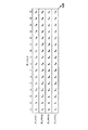
図7Aは、4つの送信アンテナ(NT=4)および16のサブバンド(NF=16)を備えた例示MIMO−OFDMシステムのためのデータシンボルブロックの逆多重化を示す。 FIG. 7A shows demultiplexing of data symbol blocks for an exemplary MIMO-OFDM system with 4 transmit antennas (N T = 4) and 16 subbands (N F = 16).
データシンボルブロックは
として示されてもよい。 May be shown as
図7Aに示される実施形態の場合、デマルチプレクシングは、それぞれ送信アンテナ1乃至4のサブバンド1上に、ブロック内の最初の4つのデータシンボルs1乃至s4が送信され、次の4つのデータシンボルs5乃至s8はサブバンド2上に送信され、以下同様であるように実行される。
For the embodiment shown in FIG. 7A, demultiplexing involves transmitting the first four data symbols s 1 to s 4 in the block on
図6Dは、MIMO−OFDMシステムにおいて同時に複数のパケットのIR送信のために使用してもよいTX空間プロセッサー130cと送信機ユニット132bのブロック図を示す。TX空間プロセッサー内に130cにおいて、マルチプレクサー/デマルチプレクサーはNpのデータシンボルブロックを受信する。但し1≦Np≦Nsであり、TX空間プロセッサー130cは、以下に図解するように、各ブロック内のデータシンボルを異なるサブバンドおよび異なる送信アンテナに供給する。マルチプレクサー/デマルチプレクサー630は、またパイロットシンボルで多重化し、NT送信アンテナのためにNT送信シンボルシーケンスを供給する。
FIG. 6D shows a block diagram of a TX
図7Bは、4つの送信アンテナ(NT=4)および16のサブバンドを備えた典型的なMIMO−OFDMシステムのための2つのデータシンボルブロック(Np=2)の多重化/逆多重化の実施形態を示す。第1のデータシンボルブロックの場合、第1の4つのデータシンボルs1,1、s1,2、s1,3、およびs1,4がそれぞれ送信アンテナ1、2、3、4のそれぞれのサブバンド1、2、3、43上に送信される。次の4つのデータシンボルs1,5、s1,6、s1,7、s1,8は、包み込まれそれぞれ送信アンテナ1、2、3、4のそれぞれのサブバンド5、6、7、8上に送信される。第2のデータシンボルブロックの場合、最初の4つのデータシンボルs2,1、s2,2、s2,3、s2,4は、それぞれ送信アンテナ3、4、1および2のそれぞれのサブバンド1、2、3、4上に送信される。次の4つのデータシンボルs2,5、s2,6、s2,7、およびs2,8は包み込まれ、それぞれ送信アンテナ3、4、1、2のそれぞれサブバンド5、6、7、8上に送信される。図7Bに示される実施形態の場合、各シンボル期間のための各送信アンテナのためのNFの周波数ドメイン値のセットは、いくつかのサブバンドの送信シンボルを含み、他のサブバンドに対してゼロを含む。
FIG. 7B shows multiplexing / demultiplexing of two data symbol blocks (N p = 2) for a typical MIMO-OFDM system with 4 transmit antennas (N T = 4) and 16 subbands. The embodiment of is shown. In the case of the first data symbol block, the first four data symbols s 1,1 , s 1,2 , s 1,3 , and s 1,4 are respectively transmitted to the transmitting antennas 1 , 2 , 3 , 4 respectively. Transmitted on
図7Bは、NFのサブバンドおよびNTの送信アンテナにわたって2つのデータシンボルブロックの送信を同時に示す。一般に、任意の数のデータシンボルブロックは、サブバンドおよび送信アンテナにわたって同時に送信してもよい。例えば、図7Bにおいて、1つ、2つ、3つ、または4つのデータシンボルブロックは、同時に送信してもよい。しかしながら、同時に確実に送信されるかもしれないデータシンボルブロックの数は、MIMOチャネルのランクに依存し、従ってNpは、Ns以下でなければならない。図7Bに示される送信スキームは、MIMOチャネルのランクに基づいて、異なる数のデータシンボルブロックを同時に送信することの容易な適応を可能にする。 FIG. 7B shows the transmission of two data symbol blocks simultaneously across NF subbands and NT transmit antennas. In general, any number of data symbol blocks may be transmitted simultaneously across subbands and transmit antennas. For example, in FIG. 7B, one, two, three, or four data symbol blocks may be transmitted simultaneously. However, the number of data symbol blocks that may be transmitted reliably at the same time depends on the rank of the MIMO channel, so N p must be less than or equal to N s . The transmission scheme shown in FIG. 7B allows easy adaptation of different numbers of data symbol blocks to be transmitted simultaneously based on the rank of the MIMO channel.
図7Bに示される実施形態の場合、各データシンボルブロックは、NFのサブバンドに亙って、対角線上におよびすべてのNTの送信アンテナから送信される。これは、同時に送信されているすべてのNPデータシンボルブロックに対して周波数および空間ダイバーシティの両方を供給する。これは、すべてのデータパケットに対して単一のレートを使用可能にする。しかしながら、また、同時に送信される異なるデータパケットに対して異なるレートを使用してもよい。異なるレートの使用は、例えば、IDDスキームを実施しないリニア受信機のようないくつかの受信機の場合よりよい性能を提供するかもしれない。異なるレートを有した複数のデータパケットの同時のIR送信は、2004年2月23日に出願された「MIMO通信システムにおける複数の並列チャネルのためのインクリメンタル冗長度送信」(Inremental Redundancy Transmission for Multiple Parallel Channels in a MIMO Communication System)というタイトルの同一出願人により米国特許出願シリアル番号第10/785,292に記載されている。 For the embodiment shown in FIG. 7B, each data symbol block, over the subbands N F, it is transmitted diagonally and the transmitting antennas of all N T. This provides both frequency and spatial diversity for all NP data symbol blocks being transmitted simultaneously. This enables a single rate for all data packets. However, different rates may also be used for different data packets transmitted at the same time. The use of different rates may provide better performance than for some receivers, for example linear receivers that do not implement the IDD scheme. Simultaneous IR transmission of multiple data packets with different rates is described in “Incremental Redundancy Transmission for Multiple Parallel” filed on Feb. 23, 2004, “Incremental Redundancy Transmission for Multiple Parallels”. U.S. Patent Application Serial No. 10 / 785,292 by the same applicant entitled Channels in a MIMO Communication System.
また、周波数と空間ダイバーシティの両方を達成しながら、他の方法で、マルチプレクシング/デマルチプレクシングを実行してもよい。例えば、マルチプレクシング/デマルチプレクシングは、各送信アンテナのすべてのNFのサブバンドは、送信シンボルを運ぶために使用されるようであってもよい。各送信アンテナの全電力はPantに制限されているので、各送信シンボルのために利用可能な送信電力量は、送信シンボルを運ぶサブバンドの数に依存する。 Also, multiplexing / demultiplexing may be performed in other ways while achieving both frequency and spatial diversity. For example, multiplexing / demultiplexing may be such that all N F subbands of each transmit antenna are used to carry transmit symbols. Since the total power of each transmit antenna is limited to P ant , the amount of transmit power available for each transmit symbol depends on the number of subbands carrying the transmit symbol.
図6Dに戻って参照すると、送信機ユニット132bは、TX空間プロセッサー130cからのNTの送信シンボルシーケンスを受信して条件付けし、NTの変調された信号を発生する。
Referring back to FIG. 6D,
2. 受信機
図8Aは、図1の受信機の一実施形態である受信機150aのブロック図を示す。受信機150aにおいて、NRの受信アンテナ810a乃至810rは、送信機110により送信されたNTの変調された信号を受信し、受信機ユニット154内のそれぞれNRのRX RFユニット812a乃至812rにNRの受信された信号を供給する。各RX RFユニット812はその受信される信号に条件付けてディジタル化し、シンボル/チップのストリームを提供する。単一キャリアのMIMOシステムの場合、OFDM復調器814a乃至814rは必要なく、各RX RFユニット812は、それぞれのデマルチプレクサー816に直接シンボルのストリームを供給する。MIMO−OFDMシステムの場合、各RX RFユニット812は、それぞれのOFDM復調器814にチップのストリームを供給する。各OFDM復調器814は、(1)各受信されたOFDMシンボル内の循環プリフィックスを除去し、受信された変換されたシンボルを得る、および(2)各受信された変換されたシンボルを高速フーリエ変換(FFT)を用いて周波数ドメインに変換し、NFのサブバンドのためのNFの受信されたシンボルを得ることにより、チップのストリーム上でOFDM復調を実行する。両方のシステムの場合、デマルチプレクサー816a乃至816rは、RX RFユニット812またはOFDM復調器814からNRのシンボルストリームを受信し、各スロットのための(データのための)受信されたシンボルのNRのシーケンスをRX空間プロセッサー160aに供給し、受信されたパイロットシンボルをチャネル推定器172に供給する。
2. Receiver FIG. 8A shows a block diagram of a
RX空間プロセッサー160aは検出器820およびマルチプレクサー822を含んでいる。検出器820は、NRの受信されたシンボルシーケンスに対して空間のまたは時空の処理(または「検出」)を実行し、NTの検出されたシンボルシーケンスを得る。各検出されたシンボルは送信器によって送信されたデータシンボルの推定値である。検出器820は、最大比率結合(MRC)検出器、線形のゼロ−フォーシング(ZF)検出器(これは、またはチャネル相関マトリクス反転(CCMI)検出器とも呼ばれる)、最小平均二乗誤差(MMSE)検出器、MMSEリニアイコライザ(MMSE−LE)、決定フィードバックイコライザ(DFE)あるいは他のある検出器/イコライザを実施してもよい。検波は、空間処理が送信器で行なわれない場合、チャネル応答マトリクスHの推定値に基づいて実行してもよい。あるいは、検出は、単一キャリアMIMOシステムのための送信器において、データシンボルが送信データベースマトリクスMを用いてあらかじめ乗算されるなら、有効チャネル応答マトリクスH eff=HMに基づいて実行してもよい。簡単にするために、以下の記載は、送信ベースマトリクスMが使用されなかったと仮定する。
RX
MIMO−OFDMシステムのためのモデルは次のように表現してもよい。
s(k)は、サブバンドk上のNTの送信アンテナから送信されたNTのデータシンボルのためのNTのエントリを備えた{NT×1}である。r(k)は、サブバンドk上のNRの受信アンテナを介して得られたNRの受信されたシンボルのためのNRのエントリを備えた{NR×1}である。H(k)は、サブバンドkのための{NR×NT}のチャネル応答マトリクスである。n(k)は加法白色ガウス雑音(AWGN)のベクトルである。ベクトルn(k)は、ゼロ平均と、Λn=σ2Iの共分散マトリクスを有するように仮定される。但し、σ2は、雑音の分散であり、Iは、対角線に沿って1を有し、他のどの場所では、ゼロを有するアイデンティティマトリクスである。
s (k) is a equipped with entry N T for the data symbols of the transmitted N T from the N T transmit antennas on subband k {N T × 1}. r (k) is a equipped with entry N R for received symbols N R obtained via the N R receive antennas on subband k {N R × 1}. H (k) is the {N R × N T } channel response matrix for subband k. n (k) is a vector of additive white Gaussian noise (AWGN). The vector n (k) is assumed to have a zero mean and a covariance matrix of Λ n = σ 2 I. Where
MIMO−OFDMシステムの場合、受信機は、データ送信のために使用されるサブバンドの各々に対して別個に検出を実行する。以下の記載は1つのサブバンドの場合である。そして簡単のためにサブバンドインデックスkは、数学的微分において省略されている。また、以下の記載は単一キャリアMIMOシステムに対して適用可能である。簡単にするために、ベクターsはNTの送信アンテナから送られたNTのデータシンボルを含むと仮定される。 For MIMO-OFDM systems, the receiver performs detection separately for each of the subbands used for data transmission. The following description is for one subband. For the sake of simplicity, the subband index k is omitted in the mathematical differentiation. The following description is applicable to a single carrier MIMO system. For simplicity, the vector s is assumed to contain data symbols N T transmitted from the transmission antenna of the N T.
MRC検出器による空間処理は次のように表現してもよい。
但しW mrcは、MRC検出器の応答であり、これはW mrc=Hである。
は、MRC検出器のための検出されたシンボルの{NT×1}ベクトルである。”H”は共役転置である。 Is a {N T × 1} vector of detected symbols for the MRC detector. “H” is a conjugate transpose.
送信アンテナiのための検出されたシンボルは、
として表してもよい。但し、w mrc,iはW mrcのi番目の列であり、h iは送信アンテナiとNRの受信アンテナとの間のチャネル応答ベクトルである。 May be expressed as Where w mrc, i is the i th column of W mrc and h i is the channel response vector between transmit antenna i and N R receive antennas.
MMSE検出器による空間処理は次のように表現してもよい。
但しW mmse=(HH H+σ2I)−1Hは、MMSE検出器のためのものである。送信アンテナiのためのMMSE検出器応答は、wmmse,i=(HH H+σ2I)-1 h iとして表してもよい。 Where W mmse = ( HH H + σ2 I ) -1 H is for the MMSE detector. The MMSE detector response for transmit antenna i may be expressed as w mmse, i = ( HH H + σ 2 I ) −1 h i .
ゼロフォース検出器による空間処理は以下のように表してもよい。
ただし、W zf=H(H H H)-1はゼロフォース検出器のためのものである。送信アンテナiのためのゼロフォース検出器応答は、w zf=h i(H H H)-1として表してもよい。 Where W zf = H ( H H H ) −1 is for the zero force detector. Zero Force detector response for transmit antenna i may be expressed as w zf = h i (H H H) -1.
スロットごとに、検出器820は、
のNTのエントリに相当するNTの検出されたシンボルシーケンスを供給する。マルチプレクサー822は検出器820からNTの検出されたシンボルシーケンスを受信し、送信器においてTX空間プロセッサー130によって行なわれた処理に相補的な処理を実行する。図6Aおよび6CにおけるTX空間プロセッサー130aのような各スロットにおいて唯一つのデータシンボルブロックが送信されるなら、マルチプレクサー822は、NTのシーケンス内で検出されたシンボルを1つの検出されたシンボルブロックに多重化する。それぞれ図6Bおよび6DにおけるTAX空間プロセッサー130bおよび130cのような各スロットにおいて複数のデータシンボルブロックが送信されるなら、マルチプレサー822は、NTのシーケンス内の検出されたシンボルを(図8Aに図示しない)NPの検出されたシンボルに逆多重化する。いずれの場合にも、各検出されたシンボルブロックは、送信機により送信されたデータシンボルブロックの推定値である。
N T detected symbol sequences corresponding to N T entries are provided.
チャネル推定器172は、(例えば、受信されたパイロットシンボルに基づいて)MIMOチャネルのためのチャネル応答マトリクスHおよび受信機における雑音レベルを推定し、チャネル推定値をコントローラー180に供給する。
コントローラー180内では、マトリクス計算ユニット176は、上に記述されるように、推定されたチャネル応答マトリクスに基づいて検出器応答W(W mrc、W mmse、またはW zfであってもよい)を導き出し、検出器応答を検出器820に供給する。検出器820は、受信されたシンボルのベクトルrを検出器応答Wと予め乗算し、検出されたシンボルのベクトル
を得る。レートセレクター174(それは、図8Aで示される受信機の実施形態のためのコントローラー180によって実施される)は、下記に述べられるように、チャネル推定値に基づいてレート選択を実行する。ルックアップ表(LUT)184は、MIMOシステムによりサポートされたレートのセットおよび各レートに関連するパラメーター値のセット(例えば、データレート、パケットサイズ、コーディングスキームまたはコードレート、各レートのための変調スキーム等)を記憶する。レートセレクター174は、レート選択に使用される情報のためにLUT184をアクセスする。
Get. A rate selector 174 (which is implemented by the
図8Bは、図1および8AにおけるRXデータプロセッサー170の一実施形態である、RXデータプロセッサー170aのブロック図を示す。RXデータプロセッサー170a内では、シンボルデマッピングユニット830は、一度に1つのブロックの割合でRXデータプロセッサー160aから検出されたシンボルブロックを受信する。検出されたシンボルブロック毎に、シンボルデマッピングユニット830は、(コントローラー180からの復調制御により示されるように)そのブロックに使用される変調スキームに従って検出されたシンボルを復調し、復調されたデータブロックをチャネルインターリーバー840に供給する。チャンネルデインターリーバー840はデマルチプレクサー842とNBのブロックデインターリーバー844a乃至844nbを含む。新しいデータパケットを受信する前に、ブロックデインターリーバー844a乃至844nbは消去を用いて初期化される。消去は、逸失したコードビットの代わりをし(すなわち、まだ受信していないコードビット)、デコーディングプロセスにおいて適切な重みが与えられる。
FIG. 8B shows a block diagram of an RX data processor 170a, which is one embodiment of
マルチプレクサー842はシンボルデマッピングユニット830から復調されたデータブロックを受信し、各復調されたデータブロックを適切なブロックインターリーバー844に供給する。各ブロックデインターリーバー844は、そのブロックに対して送信機において実行されたインターリービングに相補的な方法でそのブロック内の復調されたデータをデインターリーブする。インターリービングが選択されたレートに依存する場合、破線によって示されるように、コントローラー180は、デインターリービング制御をブロックデインターリーバー844に供給する。
Multiplexer 842 receives the demodulated data blocks from symbol demapping unit 830 and provides each demodulated data block to the appropriate block interleaver 844. Each block deinterleaver 844 deinterleaves the demodulated data in that block in a manner complementary to the interleaving performed at the transmitter for that block. If the interleaving depends on the selected rate, the
新しいデータシンボルブロックがデータパケット用の送信器から受信される場合は常に、復号は、そのパケットのために受信されたすべてのブロック上で新たに行なわれる。 Whenever a new data symbol block is received from the transmitter for a data packet, decoding is performed anew on all blocks received for that packet.
再アセンブリーユニット848は、次の復号のためのデインターリーブされたデータのパケットを形成する。デインターリーブされたパケットは、(1)現在のパケットのために受信されたすべてのデータシンボルブロックのためのデイタンーリーブされたデータブロックおよび(2)現在のパケットのために受信されないデータシンボルブロックのための消去を含む。再アセンブリーユニット848は、コントローラー180からの再アセンブリー制御により示されるように、送信機により実行される分割と相補的な方法で再アセンブリーを実行する。
FECデコーダー850は、コントローラー180からのデコーディング制御によって示されるように、送信器において実行されるFEC符号化に対する相補的な方法で、デインターリーブされたデータパケットを復号する。例えば、ターボコーディングまたは畳み込みコーディングがそれぞれ送信機において実行されるなら、ターボデコーダーまたはビタビデコーダーは、FECデコーダー850のために使用してもよい。FECデコーダー850は現在のパケットのための復号されたパケットを提供する。CRCチェッカー852は、復号されたパケットをチェックし、パケットが正しく復号されたかまたはエラーで復号されたかどうかを決定し、復号されたパケットのステータスを供給する。
The
図9Aは、受信機150bのブロック図を示す。受信機150bは図1の受信機150の他の実施形態である。受信機150bは反復検出およびデコーディング(IDD)スキームを実施する。明確にするために、IDDスキームは図4Bおよび5に示すコーディングスキームのために以下に記載される。コーディングスキームは、データパケットを3つの部分に符号化する。すなわち、システマティックビット{cdata}、第1パリティビット{cp1}、および第2パリティビット{cp2}である。
FIG. 9A shows a block diagram of the
受信機150bは、復号されたパケットを得るためにデータパケットのための受信されたシンボル上で反復検出およびデコーディングを実行する検出器920およびFECデコーダー950を含む。IDDスキームは、チャネルコードのエラー訂正機能を利用し、改良された性能を提供する。これは、以下に記載するように、Nddの反復のための検出器920とFECデコーダー950との間で演繹的情報を反復的にわたすことにより達成される。但し、Ndd>1である。演繹的な情報は、送信ビットの可能性を示す。
受信機150bはRX空間プロセッサー160bとRXデータプロセッサー170bを含んでいる。RX空間プロセッサー160b内では、バッファー918は、スロットごとに受信機ユニット154によって供給される受信されたシンボルシーケンスを受信し記憶する。データパケットに対して送信機から新しいデータシンボルブロックが受信されるときはいつも、そのパケットに対して受信されるすべてのブロックに対して受信されたシンボル上で新しく(すなわち、開始から)反復検出およびデコーディングが実行される。
検出器920は、受信されたブロックごとにNRの受信されたシンボルシーケンス上で空間処理または検出を実行し、そのブロックのためのNTの検出されたシンボルシーケンスを供給する。検出器920はMRC検出器、ゼロ−フォーシング検出器(MMSE検出器)、または他のある検出器/イコライザを実施してもよい。明確にするために、MMSE検出器を備えた検出は以下に記載される。
反復検出およびデコーディングを備えたMMSE検出器の場合、送信アンテナiのための検出されたシンボル
は、以下のように表してもよい。
但し、w iおよびuiは、MMSE基準に基づいて導き出される。MMSE基準は次のように表すことができる。
式(7)において提起された最適化問題に対する解法は以下のように表すことができる。
但し、h iはチャネル応答マトリクスHのi番目の列である。H iはi番目の列をゼロに設定した場合Hに等しい。s iは、sのi番目の要素を除去することにより得られる{(NT-1)×1}ベクトルである。E[a]は、ベクトルaのエントリの期待値である。VAR[aa H]は、ベクトルaの共分散マトリクスである。マトリクスPは、送信アンテナiのためのチャネル応答ベクトルh iの外積である。マトリクスQは、送信アンテナiに対する干渉の共分散マトリクスである。ベクトルzは、送信アンテナiに対する干渉の期待値である。式(6)は以下のように簡単化することができる。
但し
であり、ηiはゼロ平均および
の分散を有したガウス雑音サンプルである。ガウス雑音サンプルηiは、他の送信アンテナからの干渉は、MMSE検出器のあとのガウス分布であると仮定する。ガウス雑音サンプラーは、他の送信アンテナからの干渉がMMSE検出器の後のガウス分布であると仮定する。 Gaussian noise sample with a variance of. The Gaussian noise sample η i assumes that the interference from other transmit antennas is a Gaussian distribution after the MMSE detector. The Gaussian noise sampler assumes that the interference from other transmit antennas is a Gaussian distribution after the MMSE detector.
以下の記載では、上付きの添え字nは、n番目の検出/デコーディング反復を示し、上付きの添え字mは、リカバーされる現在のパケットのために受信されるm番目のデータシンボルブロックを示す。第1の反復の場合(すなわち、n=1)、演繹的情報がFECデコーダーから利用できないので、検出はもっぱら受信したシンボルに基づく。それゆえ、「1」または「0」である等価な確率を有するビットが仮定される。この場合、方程式(8)はリニアMMSE検出器に変形する。これは
として与えることができる。次の反復毎に(すなわち、n>1)、FECデコーダーにより供給される演繹情報は検出器により使用される。反復数が増加するにつれ、干渉は低減し、検出器は、フルダイバーシティを得るMRC検出器に集中する。 Can be given as. At each subsequent iteration (ie, n> 1), the deductive information provided by the FEC decoder is used by the detector. As the number of iterations increases, the interference decreases and the detector concentrates on the MRC detector that obtains full diversity.
現在のパケットに対して受信されたデータシンボルブロック毎に、図9Aの検出器920は、そのブロックのためのNRの受信されたシンボルシーケンス上で検出を実行し、NTの検出されたシンボルシーケンスを供給する。マルチプレクサー922は、NTのシーケンス内で検出されたシンボルを多重化し、検出されたシンボルブロックを得る。検出されたシンボルブロックは、RXデータプロセッサー170bに供給される。m番目のデータシンボルブロックのためのn番目の検出/デコーディング反復において得られた検出されたシンボルブロックは
として示される。 As shown.
RXデータプロセッサー170b内では、ログ尤度比(LLR)計算ユニット930は、RX空間プロセッサー160bから検出されたシンボルを受信し、各検出されたシンボルのためのBコードビットのLLRsを計算する。各検出されたシンボル
はデータシンボルsiの推定値である。データシンボルsiの推定値は、Bコードビットbi=[bi,1 bi,2・・・bi,B]を信号コンステレーションのあるポイントにマッピングすることにより得られる。検出されたシンボル
のj番目のビットのためのLLRは以下のように表してもよい。
但し、bi,jは検出されたシンボル
のためのj番目のビットである。
は、1であるビットbi,jを有した検出されたシンボル
の確率である。
は、−1であるビットbi,jを有する検出されたシンボル
の確率である。 Is the probability.
xi,jはビットbi,jのLLRである。LLRs{xi,j}は検出器によりFECデコーダーに供給される演繹情報を表し検出器LLRsとも呼ばれる。 x i, j is the LLR of bits b i, j . LLRs {x i, j } represents deductive information supplied by the detector to the FEC decoder and is also referred to as detector LLRs.
簡単にするために、各検出されたシンボル
のためのBビットは、独立であるようにインターリービングは仮定される。方程式(14)は以下のように表してもよい。
但しΩj,qはj番目のビットがqに等しい信号コンステレーション内のポイントの集合である。sは変調シンボルまたは評価される集合Ωj,qのポイント(すなわち、仮定されたシンボル)である。αiは、送信アンテナのためのおよび上で定義された利得である。viは検出されたシンボル
のためのガウス雑音サンプルηiの分散である。b iは仮定されたシンボルsのためのBビットの集合である。b i(j)はj番目のビットが除去されたb iに等しい。L iは仮定されたシンボルsのBビットのためのFECデコーダーから得られたLLRsの集合である。L i(j)は、j番目のビットのためのデコーダーLLRが除去されたL iに等しい(すなわち、
である)。"T"は、転置を示す。(i、j)番目のビットのためのデコーダーLLRは、以下のように表すことができる。
但し、Pr(bi,j=1)はビットbi,jが1である確率である。Pr(bi,j=−1)はビットbi,jが−1である確率である。 However, Pr (b i, j = 1) is the probability that the bit b i, j is 1. Pr (b i, j = −1) is the probability that the bit b i, j is −1.
第1の反復(n=1)の場合、ビットのための演繹的情報が利用可能でないので、各ビットが1または−1である等価な確率を示すためにL i(j)のエントリのすべてがゼロに設定される。次の反復毎に、L i(j)のエントリは、FECデコーダーからのビットのための「ソフト」値に基づいて計算される。LLR計算ユニット930は、RX空間プロセッサー160bから受信された、各検出されたシンボルのコードビットに対してLLRを供給する。m番目のデータシンボルブロックのためのn番目の検出/デコーディング反復において得られるLLRsのブロックは、
として示される。 As shown.
チャネルデインターリーバー940は、LLR計算ユニット930からLLRの各ブロックを受信し、デインターリーブし、ブロックのためのデインターリーブされたLLRsを供給する。再アセンブリーユニット948は、(1)送信機から受信されたすべてのデータシンボルブロックのためのチャネルデインターリーバー940からのデインターリーブされたLLRsのブロックおよび(2)受信されないデータシンボルブロックのためのゼロ値のLLRsのブロックを含むLLRsのパケットを形成する。n番目の検出/復号反復のためのLLRsのパケットは、{xn}として示される。以下に記載されるように、FECデコーダー950は、再アセンブリーユニット948からのLLRsのパケットを受信しデコードする。
図9Bは、それぞれ図9Aおよび8BのFECデコーダー950および850に使用してもよいターボデコーダー950aのブロック図を示す。ターボデコーダー950aは、図4Bで示されるもののような並列の連結した畳み込み符号のための反復復号を行なう。
FIG. 9B shows a block diagram of a
Turboデコーダー950a内では、デマルチプレクサー952は、(入力LLRsとしても示される)再アセンブリーユニット948からのLLRs{xn}のパケットを受信して、ビットLLRs
、第1パリティビットLLRs
および第2パリティビットLLRs
に逆多重化する。ソフト入力ソフト出力(SISO)デコーダー954aは、デマルチプレクサー952からのデータビットLLRs
と第1パリティビットLLRs
およびコードデインターリーバー958からのデインターリーブされたデータビットLLRs
を受信する。次に、SISOデコーダー954aは、第1の構成要素である畳み込み符号に基づいて、データのための新しいLLRsと第1のパリティビット
を導き出す。コードインターリーバー956は、送信機において使用されるコードインターリービングスキームに従ってデータビットLLRs{xdata}をインターリーブし、インターリーブされたデータビットLLRs
を供給する。 Supply.
同様に、SISOデコーダー954bは、デマルチプレクサー952からデータビットLLRs
と第2のパリティビットLLRs
を受信するとともに、コードインターリーバー956からインターリーブされたデータビットLLRs
を受信する。次に、SISOデコーダー954bは、第2の構成要素である畳み込み符号に基づいて、データのための新しいLLRsと第2のパリティビット
を導き出す。コードデインターリーバー958はコードインターリービングに対して相補的な方法でデータビットLLRs{xdata2}をデイタンーリーブし、デインターリーブされたデータビットLLRs
を供給する。SISOデコーダー954aおよび954bは、BCJR SISO最大帰納的(MAP)アルゴリズムまたはそのより低い複雑性導関数、ソフト出力ビタビ(SOV)アルゴリズム、または他のあるデコーディングアルゴリズムを実施してもよい。これらのアルゴリズムは技術的に知られている。
Supply.
SISO復号器954aおよび954bによる復号は現在の検出/デコーディング反復nに対してNdec回反復される。但しNdec>1である。すべてのNdecのデコーディング反復が完了した後で、結合器/マルチプレクサー960は、SISOデコーダー954aから最後のデータビットLLRs{xdata1}と、最後の第1パリティビットLLRs
を受信し、コードデインターリーバー958からデインターリーブされた最後のデータビットLLRs
を受信し、SISOデコーダー954bから最後の第2パリティビットLLRs
を受信する。次に、結合器/マルチプレクサー960は、以下のように次の検出/デコーディング反復n+1のためのデコーダーLLRs
を計算する。
デコーダーLLRs
は方程式(16)内のλi,jに相当し、FECデコーダーにより検出器に供給される演繹情報を表す。 Corresponds to λ i, j in equation (16) and represents the deductive information supplied to the detector by the FEC decoder.
すべてのNddの検出/デコーディング反復が完了した後で、結合器/マルチプレクサー960は、以下のように最後のデータビットLLRs{xdata}を計算する。
但し、
は最後の検出/デコーディング反復のためにLLR計算ユニット930により供給されるデータビットLLRsである。スライサー962は、最後のデータビットLLRs{xdata}をスライスし、リカバーされるパケットのための復号されたパケット
を供給する。 Supply.
CRCチェッカー968は復号されたパケットをチェックし、パケットステータスを供給する。
A
図9Aに戻ると、FECデコーダー950からのデコーダーLLRs
は、チャネルインターリーバー970によりインターリーブされ、インターリーブされたデコーダーLLRsは検出器920に供給される。検出器920は、受信したシンボル{rm}とデコーダーLLRs
に基づいて新しく検出されたシンボル
を導き出す。デコーダーLLRs
は、(a)方程式(12)内のzを導き出すために使用される干渉の期待値(すなわち、E[si]、および(b)方程式(11)内のQを導き出すために使用される干渉の分散(すなわち、VAR[s i])を計算するために使用される。 (A) Expected value of interference used to derive z in equation (12) (ie, E [si], and (b) interference used to derive Q in equation (11). Is used to calculate the variance (ie, VAR [ s i ]).
上述したように、RX空間プロセッサー160aからのすべての受信されたデータシンボルブロックのための検出されたシンボル
は、RXデータプロセッサー170bにより再びデコードされる。検出およびデコーディングプロセスはNdd回反復される。反復検出およびデコーディングプロセスの期間に、検出されたシンボルの信頼性は、各検出/デコーディング反復を用いて改善する。
Are decoded again by the
方程式(8)に示されるように、MMSE検出器応答w iはQに依存する。Qは、干渉の分散VAR[s i]に依存する。Qは、各検出/デコーディング反復に対して異なるので、MMSE検出器応答w iも各反復に対して異なる。受信機150bを単純化するために、検出器920は(1)Nddi検出/デコーディング反復のためのMMSE検出器および(2)Ndd2の検出/デコーディング反復のためのMRC検出器(または反復とともに変わらない応答を有するある他のタイプの検出器/イコライザ)を実施してもよい。この場合、Ndd1およびNdd2は各々1またはそれより大きい値であり得る。例えば、MMSE検出器は、第1の検出/デコーディング反復に使用してもよく、MRC検出器は、次の5つの検出/デコーディング反復に使用してもよい。別の例として、MMSE検出器は、最初の2つの検出/デコーディング反復に使用されてもよい。また、MRC検出器は次の4つの検出/デコーディング反復に使用されてもよい。
As shown in equation (8), the MMSE detector response w i depends on Q. Q depends on the interference variance VAR [ s i ]. Since Q is different for each detection / decoding iteration, the MMSE detector response w i is also different for each iteration. To simplify
MRC検出器は、方程式(6)で示すように、項uiを用いて実施してもよい。この場合、w mrc,iをw iと交換する。方程式(6)、(9)、(12)で示されるように、項uiは、干渉の期待値E[s i]に依存する。受信機150bをさらに簡単化するために、項uiは、MMSE検出器からMRC検出器に切り替えた後で省略してもよい。
The MRC detector may be implemented with the term u i as shown in equation (6). In this case, replace w mrc, i with w i . As shown in equations (6), (9), and (12), the term u i depends on the expected value E [ s i ] of interference. To further simplify
反復検出およびデコーディングスキームは種々の利点を提供する。 Iterative detection and decoding schemes provide various advantages.
例えば、IDDスキームは、NTの送信アンテナを介して同時に送信されたすべてのデータパケットのための単一レートをサポートし、周波数選択フェージングに対抗することができ、図4Bに示される並列に連結された畳み込み符号を含む種々のコーディングおよび変調スキームと一緒に柔軟に使用してもよい。 For example, the IDD scheme supports a single rate for all data packets transmitted simultaneously via NT transmit antennas and can combat frequency selective fading and is concatenated in parallel as shown in FIG. 4B. It may be used flexibly with various coding and modulation schemes including convolutional codes.
3. レート選択
単一キャリアMIMOシステムおよびMIMO−OFDMシステムの両方の場合、受信機および/または送信機は、MIMOチャネルを推定することができ、MIMOチャネル上のデータ送信のための適切なレートを選択することができる。レート選択は種々の方法で実施してもよい。いくつかの例示レート選択スキームは、以下に記載される。
3. Rate Selection For both single carrier MIMO systems and MIMO-OFDM systems, the receiver and / or transmitter can estimate the MIMO channel and select an appropriate rate for data transmission on the MIMO channel. be able to. Rate selection may be performed in various ways. Some exemplary rate selection schemes are described below.
第1のレート選択スキームにおいて、MIMOチャネル上のデータ送信のためのレートは、ある基準に基づいて選択される。この基準は、NTの送信アンテナのためのチャネル応答をモデル化する等価システムを用いて導き出される。等価システムは、AWGNチャネル(すなわち、フラットな周波数応答を有した)およびNTの送信アンテナの平均スペクトル効率に等しいスペクトル効率を有するように定義される。等価システムは、NTの送信アンテナの合計容量に等しい合計容量を有する。平均スペクトル効率は(1)送信アンテナ毎に受信されたSNRを推定する(例えば、受信されたパイロットおよび/またはデータシンボルに基づいて)、(2)受信されたSNRから各送信アンテナのスペクトル効率を計算するおよび(制約されたまたは非制約された)スペクトル効率関数、f(x)に基づいて、および(3)個々の送信アンテナのスペクトル効率に基づいてNTの送信アンテナの平均スペクトル効率を計算することにより決定してもよい。測定基準は、平均スペクトル効率をサポートするために等価なシステムにより必要とされるSNRとして定義してもよい。このSNRは、平均スペクトル効率からおよび逆関数f-1(x)に基づいて決定してもよい。 In a first rate selection scheme, the rate for data transmission on the MIMO channel is selected based on certain criteria. This criterion is derived using an equivalent system that models the channel response for N T transmit antennas. An equivalent system is defined to have a spectral efficiency equal to the average spectral efficiency of the AWGN channel (ie, having a flat frequency response) and NT transmit antennas. The equivalent system has a total capacity equal to the total capacity of N T transmit antennas. Average spectral efficiency (1) estimates the received SNR for each transmit antenna (eg, based on received pilot and / or data symbols), and (2) determines the spectral efficiency of each transmit antenna from the received SNR. Calculate and calculate the average spectral efficiency of the NT transmit antennas based on the spectral efficiency function (constrained or unconstrained), f (x), and (3) based on the spectral efficiency of the individual transmit antennas You may decide by. A metric may be defined as the SNR required by an equivalent system to support average spectral efficiency. This SNR may be determined from the average spectral efficiency and based on the inverse function f −1 (x).
システムは、レートのセットをサポートするように設計してもよい。 The system may be designed to support a set of rates.
サポートされるレートの1つは、ヌルレートのためのもの(すなわち、ゼロのデータレート)であってもよい。残りのレートの各々は、特定のノンゼロデータレート、特定のコーディングスキームまたはコードレート、特定の変調スキーム、およびAWGNチャネルのための性能の目標レベル(例えば、1%PER)を達成するのに必要な特定の最小SNRに関連する。ノンゼロデータレートを有した各サポートされたレートの場合、必要なSNRは、特定のシステム設計(すなわち、そのレートのためにシステムにより使用される、特定のコードレート、インターリービングスキーム、変調スキーム等)に基づいて、およびAWGNチャネルのために得られる。当技術分野で周知のように必要なSNRは、コンピューターシミュレーション、経験に基づく測定等により得てもよい。サポートされたレートのセットおよびそれらの必要なSNRsは、ルックアップテーブル(例えば、図8AのLUT184)に記憶してもよい。
One of the supported rates may be for a null rate (ie, a data rate of zero). Each of the remaining rates is necessary to achieve a target level of performance (eg, 1% PER) for a specific non-zero data rate, a specific coding scheme or code rate, a specific modulation scheme, and an AWGN channel. Associated with a specific minimum SNR. For each supported rate with a non-zero data rate, the required SNR is the specific system design (ie, the specific code rate, interleaving scheme, modulation scheme, etc. used by the system for that rate) And for the AWGN channel. As is well known in the art, the required SNR may be obtained by computer simulation, experience-based measurements, and the like. The set of supported rates and their required SNRs may be stored in a lookup table (eg,
測定基準はシステムによりサポートされるレートの各々のための必要なSNRに対して比較してもよい。測定基準以下である必要なSNRを有した最も高いレートはMIMOチャネル上のデータ送信に使用するために選択される。第1のレート選択スキームは、2002年6月20日に出願された、「マルチチャネル通信システムのためのレート制御](Rate Control for Multi-Channel Communication System)というタイトルの同一出願人による米国特許出願シリアル番号第10/176,567に詳細に記載されている。
The metrics may be compared against the required SNR for each of the rates supported by the system. The highest rate with the required SNR that is below the metric is selected for use for data transmission on the MIMO channel. The first rate selection scheme is a US patent application filed on June 20, 2002 by the same applicant entitled “Rate Control for Multi-Channel Communication System”. It is described in detail in
第2のレート選択スキームにおいて、MIMOチャネル上のデータ送信のためのレートは、NTの送信アンテナのための受信されたSNRsに基づいて選択される。 In a second rate selection scheme, the rate for data transmission on the MIMO channel is selected based on received SNRs for the NT transmit antennas.
各送信アンテナのための受信されたSNRが最初に決定され、次に、平均受信SNR、γrx,avgがNTの送信アンテナのために計算される。次に、動作するSNR、γopが、平均受信SNR、γrx,avgおよびSNRオフセットまたはバックオフファクター(back-off factor)γos(例えば、γop=γrx+γos、但し単位はdBである)に基づいてNTの送信アンテナのために計算される。SNRオフセットは推定誤差、MIMOチャネルのばらつきおよび他の要因に対処するために使用される。動作するSNR、γopは、システムによりサポートされるレートの各々のための必要なSNRに対して比較してもよい。動作するSNR以下である必要なSNRを有した最も高いレート(すなわち、γreq<γop)は、MIMOチャネル上のデータ送信に使用するために選択される。第2のレート選択スキームは、2003年3月20日に出願された「マルチチャネル通信システムにおけるデータ送信のための送信モード選択」(Transmission Mode Selection for Data Transmission in a Multi-Channel Communication System)というタイトルの同一出願人により米国特許出願シリアル番号第10/394,529に詳細に記載されている。 The received SNR for each transmit antenna is first determined, and then the average received SNR, γ rx, avg is calculated for the NT transmit antennas. Next, the operating SNR, γ op is the average received SNR, γ rx, avg and SNR offset or back-off factor γ os (eg, γ op = γ rx + γ os , where the unit is dB) Calculated for N T transmit antennas. The SNR offset is used to account for estimation errors, MIMO channel variations and other factors. The operating SNR, γ op , may be compared against the required SNR for each of the rates supported by the system. The highest rate with the required SNR that is less than or equal to the operating SNR (ie, γ req <γ op ) is selected for use for data transmission on the MIMO channel. The second rate selection scheme is entitled “Transmission Mode Selection for Data Transmission in a Multi-Channel Communication System” filed on March 20, 2003. Of U.S. Patent Application Serial No. 10 / 394,529.
ここに記載されたIR送信技術は、種々の手段により実施してもよい。 The IR transmission techniques described herein may be implemented by various means.
例えば、これらの技術は、ハードウェア、ソフトウェアあるいはそれらの組合せにおいて実施してもよい。ハードウェアで実施する場合、IR送信のために送信機において使用される処理ユニットは、1つ以上の特定用途向け集積回路(ASICs)、ディジタルシグナルプロセッサー(DSP)、ディジタル信号処理装置(DSPD)、プログラマブルロジックデバイス(PLD)、フィールドプログラマブルゲートアレイ(FPGA)、プロセッサー、コントローラー、マイクロコントローラ、ここに記載された機能を実行するように設計された他の電子ユニットまたはそれらの組み合わせ内で実施してもよい。IR送信を受信するために受信機において使用される処理装置も1つ以上のASICs、DSPs、DSPDs、PLDs、FPGAs、プロセッサー、コントローラー等内で実施してもよい。 For example, these techniques may be implemented in hardware, software, or a combination thereof. When implemented in hardware, the processing units used at the transmitter for IR transmission are one or more application specific integrated circuits (ASICs), digital signal processors (DSPs), digital signal processors (DSPDs), May be implemented within a programmable logic device (PLD), field programmable gate array (FPGA), processor, controller, microcontroller, other electronic units designed to perform the functions described herein, or combinations thereof. Good. The processing devices used at the receiver to receive IR transmissions may also be implemented within one or more ASICs, DSPs, DSPDs, PLDs, FPGAs, processors, controllers, and the like.
ソフトウェア実施の場合、IR送信技術は、ここに記載された機能を実行するモジュール(例えば、手続、機能等)を用いて実施してもよい。 For software implementations, IR transmission techniques may be implemented using modules (eg, procedures, functions, etc.) that perform the functions described herein.
ソフトウェアコードは、メモリユニット(例えば、図1のメモリユニット142および182に)に記憶してもよく、プロセッサー(例えば、コントローラー140および180)により実行してもよい。メモリユニットは、プロセッサー内部でまたはプロセッサー外部で実施してもよい。プロセッサー外部で実施する場合、メモリユニットは、当該技術分野で周知のように、種々の手段を介してプロセッサーに通信可能に接続することができる。
The software code may be stored in a memory unit (eg, in
見出しは、参考のために、およびあるセクションを見つけることを補助するためにここに含まれている。これらの見出しは、見出しの下に記載された概念の範囲を制限することを意図したものではなく、これらの概念は、明細書全体にわたって他のセクションに適用可能性を有していてもよい。 Headings are included here for reference and to help you find certain sections. These headings are not intended to limit the scope of the concepts described under the headings, and these concepts may have applicability to other sections throughout the specification.
開示された実施形態の上述の記載は、技術に熟達したいかなる人もこの発明を製作しまたは使用することを可能にするために提供される。 The above description of the disclosed embodiments is provided to enable any person skilled in the art to make or use the present invention.
これらの実施形態への種々の変更は、当業者に容易に明白であり、ここに定義される包括的原理は、この発明の精神または範囲を逸脱することなく他の実施形態に適用してもよい。 Various modifications to these embodiments will be readily apparent to those skilled in the art, and the generic principles defined herein may be applied to other embodiments without departing from the spirit or scope of the invention. Good.
従って、この発明は、ここに示される実施形態に限定されることを意図したものではなく、ここに開示される原理と新規な特徴に最も一致する範囲が許容されるべきである。 Accordingly, the present invention is not intended to be limited to the embodiments shown herein, but is to be accorded the scope that most closely matches the principles and novel features disclosed herein.
Claims (38)
送信機における複数の送信アンテナと受信機における複数の受信アンテナとの間のMIMOチャネル上のデータ送信に関する選択されたレートを取得することと、
前記選択されたレートに従ってデータパケットを処理し、複数のシンボルブロックを得ることと、ここにおいて各シンボルブロックは前記データパケットに関する異なる符号化された情報を含む、
前記データパケットが前記受信機により正しくリカバーされるまでまたは前記複数のシンボルブロックのすべてが送信されるまで、一度に1つのシンボルブロックの割合で、前記複数のシンボルブロックの少なくとも1つを送信することと、ここにおいて、各送信されたシンボルブロックは前記送信機において前記複数の送信アンテナの全てから送信される、
を備えた方法。In a method for performing incremental redundancy (IR) transmission in a wireless multiple input multiple output (MIMO) communication system,
Obtaining a selected rate for data transmission on a MIMO channel between multiple transmit antennas at a transmitter and multiple receive antennas at a receiver;
Processing a data packet according to the selected rate to obtain a plurality of symbol blocks, wherein each symbol block includes different encoded information about the data packet;
Transmitting at least one of the plurality of symbol blocks at a rate of one symbol block at a time until the data packet is correctly recovered by the receiver or until all of the plurality of symbol blocks are transmitted. Where each transmitted symbol block is transmitted from all of the plurality of transmit antennas at the transmitter,
With a method.
符号化されたパケットを得るために前記選択されたレートによって示されたコーディングスキームに従って前記データパケットを符号化することと、
前記符号化されたパケットを複数の符号化されたサブパケットに分割することと、
前記選択されたレートにより示される変調スキームに従って前記複数の符号化されたサブパケットを変調し、前記複数のシンボルブロックを得ることと、
を含む、請求項1の方法。The process is
Encoding the data packet according to a coding scheme indicated by the selected rate to obtain an encoded packet;
Splitting the encoded packet into a plurality of encoded subpackets;
Modulating the plurality of encoded subpackets according to a modulation scheme indicated by the selected rate to obtain the plurality of symbol blocks;
The method of claim 1 comprising:
前記NAKを受信することに応答して前記複数のシンボルブロックの残りのシンボルブロックの中で次のシンボルブロックを送信することと、
をさらに備えた、請求項1の方法。Receiving a negative acknowledgment (NAK) for the data packet;
Transmitting a next symbol block among the remaining symbol blocks of the plurality of symbol blocks in response to receiving the NAK;
The method of claim 1 further comprising:
前記送信機における複数の送信アンテナと、前記受信機における複数の受信アンテナとの間のMIMOチャネル上のデータ送信に関する選択されたレートを取得し、
前記選択されたレートに従ってデータパケットを処理し、複数のシンボルブロックを取得する、ここにおいて各シンボルブロックは前記データパケットに関する異なる符号化された情報を含む、
ように機能的に作用する送信データプロセッサと、
前記データパケットが前記受信機により正しくリカバーされるまでまたは前記複数のシンボルブロックのすべてが送信されるまで、一度に1つのシンボルブロックの割合で前記複数のシンボルブロックの少なくとも1つの送信を開始する、
ように機能的に作用するコントローラーと、
を備え、
各送信されたシンボルブロックは、前記送信機において、前記複数の送信アンテナのすべてから送信される、送信機。In a transmitter that functionally operates to perform incremental redundancy (IR) transmission in a wireless multiple-input multiple-output (MIMO) communication system,
Obtaining a selected rate for data transmission on a MIMO channel between a plurality of transmit antennas at the transmitter and a plurality of receive antennas at the receiver;
Processing a data packet according to the selected rate to obtain a plurality of symbol blocks, wherein each symbol block includes different encoded information about the data packet;
A transmit data processor that functions functionally as
Start transmitting at least one of the plurality of symbol blocks at a rate of one symbol block at a time until the data packet is properly recovered by the receiver or until all of the plurality of symbol blocks are transmitted ,
And a functionally acting controller,
With
Each transmitted symbol block is transmitted from all of the plurality of transmit antennas at the transmitter.
前記選択されたレートにより示されるコーディングスキームに従って前記データパケットを符号化し、符号化されたパケットを取得し、
前記符号化されたパケットを複数の符号化されたサブパケットに分割し、
前記選択されたレートにより示される変調スキームに従って前記複数の符号化されたサブパケットを変調し、前記複数のシンボルブロックを取得する、
ように機能的作用する、請求項10の送信機。The transmission data processor is
Encoding the data packet according to a coding scheme indicated by the selected rate to obtain an encoded packet;
Dividing the encoded packet into a plurality of encoded subpackets;
Modulating the plurality of encoded subpackets according to a modulation scheme indicated by the selected rate to obtain the plurality of symbol blocks;
The transmitter of claim 10, functioning as follows.
送信機における複数の送信アンテナと、受信機における複数の受信アンテナとの間のMIMOチャネル上のデータ送信に関する選択されたレートを取得する手段と、
前記選択されたレートに従ってデータパケットを処理し、複数のシンボルブロックを取得する手段と、ここにおいて、各シンボルブロックは前記データパケットに関する異なる符号化された情報を含む、
前記データパケットが前記受信機において正しくリカバーされるまで、または前記複数のシンボルブロックのすべてが送信されるまで、一度に1つのシンボルブロックの割合で、前記複数のシンボルブロックの少なくとも1つを送信する手段と、
を備え、
各送信されたシンボルブロックは、前記送信機において前記複数の送信アンテナのすべてから送信される、装置。In an apparatus functionally operable to perform incremental redundancy (IR) transmission in a wireless multiple-input multiple-output (MIMO) communication system,
Means for obtaining a selected rate for data transmission on a MIMO channel between a plurality of transmit antennas at a transmitter and a plurality of receive antennas at a receiver;
Means for processing a data packet according to the selected rate to obtain a plurality of symbol blocks, wherein each symbol block includes different encoded information about the data packet;
Transmit at least one of the plurality of symbol blocks at a rate of one symbol block at a time until the data packet is correctly recovered at the receiver or until all of the plurality of symbol blocks are transmitted Means,
With
Each transmitted symbol block is transmitted from all of the plurality of transmit antennas at the transmitter .
前記選択されたレートにより示されるコーディングスキームに従って前記データパケットを符号化し、符号化されたパケットを得る手段と、
前記符号化されたパケットを複数の符号化されたサブパケットに分割する手段と、
前記選択されたレートにより示される変調スキームに従って前記複数の符号化されたサブパケットを変調し、前記複数のシンボルブロックを得る手段と、
を含む、請求項13の装置。The means for processing is
Means for encoding the data packet according to a coding scheme indicated by the selected rate to obtain an encoded packet;
Means for dividing the encoded packet into a plurality of encoded subpackets;
Means for modulating the plurality of encoded subpackets according to a modulation scheme indicated by the selected rate to obtain the plurality of symbol blocks;
14. The apparatus of claim 13, comprising:
データパケットのための検出されたシンボルのブロックを得ることと、ここにおいて、前記検出されたシンボルブロックは、送信機において複数の送信アンテナから送信され、受信機において複数の受信アンテナにより受信されるデータシンボルブロックの推定値であり、前記データシンボルブロックは、選択されたレートに基づいて前記データパケットに関して発生された複数のデータシンボルブロックの1つであり、各データシンボルブロックは前記データパケットに関する異なる符号化された情報を含み、1つのデータシンボルブロックは、前記複数の送信アンテナのすべてから一度に送信される、
前記データパケットに関して取得されたすべての検出されたシンボルブロックをデコードし、デコードされたパケットを供給することと、
前記デコードされたパケットが正しいかまたはエラーかを決定することと、
前記デコードされたパケットがエラーなら、前記複数のデータシンボルブロックの別のデータシンボルブロックに関して、前記取得すること、前記デコードすること、および前記決定することを反復することと、
を備えた方法。In a method for receiving incremental redundancy (IR) transmissions in a wireless multiple-input multiple-output (MIMO) communication system,
Obtaining a block of detected symbols for a data packet, wherein the detected symbol block is transmitted from a plurality of transmit antennas at a transmitter and received by a plurality of receive antennas at a receiver; An estimate of a symbol block, wherein the data symbol block is one of a plurality of data symbol blocks generated for the data packet based on a selected rate, each data symbol block being a different code for the data packet look including the reduction information, one data symbol block is transmitted at a time from all of the plurality of transmission antennas,
Decoding all detected symbol blocks obtained for the data packet and providing a decoded packet;
Determining whether the decoded packet is correct or in error;
If the decoded packet is in error, repeating the obtaining, decoding and determining with respect to another data symbol block of the plurality of data symbol blocks;
With a method.
前記受信されたシンボルブロックを検出し、前記検出されたシンボルブロックを得ること、
をさらに備えた、請求項15の方法。Obtaining a block of received symbols with respect to the data symbol block;
Detecting the received symbol block and obtaining the detected symbol block;
16. The method of claim 15, further comprising:
前記チャネル推定値に基づいて、前記レートを選択することと、
をさらに備えた、請求項15の方法。Obtaining a channel estimate for a MIMO channel between the plurality of transmit antennas and the plurality of receive antennas;
Selecting the rate based on the channel estimate;
16. The method of claim 15, further comprising:
前記複数の送信アンテナの各々に関する信号対雑音および干渉比(SNR)推定値を導き出すことと、
前記複数の送信アンテナに関するSNR推定値に基づいて前記複数の送信アンテナに関する平均スペクトル効率を決定することと、
前記複数の送信アンテナに関する前記平均スペクトル効率に基づいて前記レートを決定することと、
を含む、請求項20の方法。Selecting the rate is
Deriving a signal to noise and interference ratio (SNR) estimate for each of the plurality of transmit antennas;
Determining an average spectral efficiency for the plurality of transmit antennas based on SNR estimates for the plurality of transmit antennas;
Determining the rate based on the average spectral efficiency for the plurality of transmit antennas;
21. The method of claim 20, comprising:
前記複数の送信アンテナの各々に関する信号対雑音および干渉比(SNR)推定値を導き出すことと、
前記複数の送信アンテナに関するSNR推定値に基づいて平均SNRを計算することと、
バックオフファクターを決定することと、
前記平均SNRおよび前記バックオフファクターに基づいて前記レートを決定することと、
を含む、請求項20の方法。Selecting the rate is
Deriving a signal to noise and interference ratio (SNR) estimate for each of the plurality of transmit antennas;
Calculating an average SNR based on SNR estimates for the plurality of transmit antennas;
Determining a backoff factor;
Determining the rate based on the average SNR and the backoff factor;
21. The method of claim 20, comprising:
データパケットに関する検出されたシンボルの1ブロックを取得し、ここにおいて、前記検出されたシンボルブロックは、送信機において複数の送信アンテナから送信され、前記受信機において複数の受信アンテナにより受信された1データシンボルブロックの推定値であり、前記データシンボルブロックは、選択されたレートに基づいて、前記データパケットに関して発生された複数のデータシンボルブロックの1つであり、各データシンボルブロックは前記データパケットに関する異なる符号化された情報を含み、1つのデータシンボルブロックは、前記複数の送信アンテナのすべてから一度に送信される、
前記データパケットに関して得られたすべての検出されたシンボルブロックをデコードし、デコードされたパケットを供給し、
前記デコードされたパケットが正しいかまたはエラーかを決定する、
ように機能的に作用する受信データプロセッサーと、
前記デコードされたパケットがエラーなら、検出されたシンボルの新しいブロックを得ることと、すべての検出されたシンボルブロックをデコードすることと、前記デコードされたパケットが正しいかまたはエラーかを決定することを反復するように前記受信データプロセッサに命令するように機能的に作用するコントローラーと、
を備えた受信機。In a receiver functionally operable to receive incremental redundancy (IR) transmissions in a wireless multiple input multiple output (MIMO) communication system,
Obtaining a block of detected symbols for a data packet, wherein the detected symbol block is transmitted from a plurality of transmit antennas at a transmitter and received by a plurality of receive antennas at the receiver; An estimate of a symbol block, wherein the data symbol block is one of a plurality of data symbol blocks generated for the data packet based on a selected rate, each data symbol block being different for the data packet see containing the encoded information, one data symbol block is transmitted at a time from all of the plurality of transmission antennas,
Decoding all detected symbol blocks obtained for the data packet and providing a decoded packet;
Determining whether the decoded packet is correct or in error;
A receive data processor that functions functionally as
If the decoded packet is in error, obtain a new block of detected symbols, decode all detected symbol blocks, and determine whether the decoded packet is correct or in error. A controller operatively instructing the receiving data processor to repeat;
With receiver.
前記チャネル推定値に基づいて、前記レートを選択するように機能的に作用するレート選択器と、
をさらに備えた、請求項23の受信機。A channel estimator operatively acting to obtain a channel estimate for a MIMO channel between the plurality of transmit antennas and the plurality of receive antennas;
A rate selector functionally operable to select the rate based on the channel estimate;
24. The receiver of claim 23, further comprising:
1データパケットに関して検出されたシンボルの1ブロックを取得する手段、ここにおいて、前記検出されたシンボルブロックは、送信機における複数の送信アンテナから送信され、受信機における複数の受信アンテナにより受信される1データシンボルブロックの推定値であり、前記データシンボルブロックは、選択されたレートに基づいて、前記データパケットに関して発生された複数のデータシンボルブロックの1つであり、各データシンボルブロックは、前記データパケットの異なる符号化された情報を含み、1つのデータシンボルブロックは、前記複数の送信アンテナのすべてから一度に送信される、
前記データパケットに関して取得されたすべての検出されたシンボルブロックをデコードし、デコードされたパケットを得る手段と、
前記デコードされたパケットが正しいかまたはエラーかを決定する手段と、
前記デコードされたパケットがエラーなら、前記複数のデータシンボルの他のデータシンボルに関して前記取得すること、前記デコーディングすること、および前記決定することを反復する手段と、
を備えた装置。In an apparatus for receiving incremental redundancy (IR) transmissions in a wireless multiple-input multiple-output (MIMO) communication system,
Means for obtaining a block of detected symbols for one data packet, wherein the detected symbol blocks are transmitted from a plurality of transmit antennas at a transmitter and received by a plurality of receive antennas at a receiver; An estimate of a data symbol block, wherein the data symbol block is one of a plurality of data symbol blocks generated for the data packet based on a selected rate, wherein each data symbol block is the data packet look containing different encoded information of one data symbol block is transmitted at a time from all of the plurality of transmission antennas,
Means for decoding all detected symbol blocks obtained for said data packet to obtain a decoded packet;
Means for determining whether the decoded packet is correct or in error;
Means for repeating the obtaining, decoding and determining with respect to other data symbols of the plurality of data symbols if the decoded packet is in error;
With a device.
前記受信したシンボルブロックを検出し前記検出されたシンボルブロックを取得する手段をさらに備えた、請求項26の装置。Means for obtaining a block of received symbols with respect to the data symbol block;
27. The apparatus of claim 26, further comprising means for detecting the received symbol block and obtaining the detected symbol block.
データパケットに関する受信されたシンボルの1ブロックを受信することと、ここにおいて、前記受信されたシンボルブロックは、送信機において複数の送信アンテナから送信され、受信機において複数の受信アンテナにより受信された1データシンボルブロックに関するものであり、前記データシンボルブロックは、選択されたレートに基づいて、前記データパケットに関して発生された複数のデータシンボルブロックの1つであり、各データシンボルブロックは、前記データパケットに関する異なる符号化された情報を含む、
前記データパケットに関して受信されたすべての受信されたシンボルブロックを検出し、各受信されたシンボルブロックに関して1つの検出されたシンボルブロックの割合で検出されたシンボルブロックを取得することと、
前記データパケットに関して前記検出されたシンボルブロックをデコードし、デコーダーフィードバック情報を取得することと、
複数の反復のために前記検出およびデコーディングを実行する、ここにおいて、現在の反復のための前記デコーディングからの前記デコーダーフィードバック情報は、次の反復のための前記検出により使用されることと、
前記複数の反復の中で最後の反復のための前記デコーディングからの出力に基づいてデコードされたパケットを発生することと、
を備えた方法。In a method for receiving incremental redundancy (IR) transmissions in a wireless multiple-input multiple-output (MIMO) communication system,
Receiving a block of received symbols for a data packet, wherein the received symbol block is transmitted from a plurality of transmit antennas at a transmitter and received by a plurality of receive antennas at a receiver; A data symbol block, wherein the data symbol block is one of a plurality of data symbol blocks generated for the data packet based on a selected rate, and each data symbol block is related to the data packet Containing different encoded information,
Detecting all received symbol blocks received for the data packet and obtaining detected symbol blocks at a rate of one detected symbol block for each received symbol block;
Decoding the detected symbol block with respect to the data packet to obtain decoder feedback information;
Performing the detection and decoding for multiple iterations, wherein the decoder feedback information from the decoding for the current iteration is used by the detection for the next iteration;
Generating a decoded packet based on the output from the decoding for the last iteration of the plurality of iterations;
With a method.
前記デコードされたパケットがエラーであり、前記複数のデータシンボルブロックのすべてが送信されなかったなら、前記複数のデータシンボルブロックの他のデータシンボルブロックに関して、前記受信すること、前記検出すること、前記デコーディングすること、前記実行すること、および前記発生することを反復することと、
をさらに備えた請求項28の方法。Determining whether the decoded packet is correct or in error;
If the decoded packet is in error and all of the plurality of data symbol blocks have not been transmitted, the receiving, detecting, and other data symbol blocks of the plurality of data symbol blocks; Decoding, performing, and repeating the generating;
30. The method of claim 28 , further comprising:
前記チャネル推定値に基づいて、前記レートを選択することと、
をさらに備えた、請求項28の方法。Obtaining a channel estimate for a MIMO channel between the plurality of transmit antennas and the plurality of receive antennas;
Selecting the rate based on the channel estimate;
30. The method of claim 28, further comprising:
データパケットに関して受信されたシンボルの1ブロックを受信し記憶するように機能的に作用するバッファーと、ここにおいて、前記受信されたシンボルブロックは、送信機において複数の送信アンテナから送信され、受信機において複数の受信アンテナにより受信されるデータシンボルブロックに関するものであり、前記データシンボルブロックは、選択されたレートに基づいて、前記データパケットに関して発生された複数のデータシンボルブロックの1つであり、各データシンボルブロックは、前記データパケットに関する異なる符号化された情報を含む、
前記データパケットに関するすべての受信されたシンボルブロックを検出し、各受信されたシンボルブロックに関して1つの検出されたシンボルブロックの割合で検出されたシンボルブロックを得るように機能的に作用する検出器と、
前記データパケットに関するすべての検出されたシンボルブロックをデコードし、デコーダフィードバック情報を取得するように機能的に作用するデコーダーと、ここにおいて、前記検出器およびデコーダーは、複数の反復に関して検出およびデコーディングを実行するように機能的に作用し、現在の反復に関して前記デコーダーからの前記デコーダーフィードバック情報は、次の反復に関して前記検出器により使用され、デコードされたパケットは、前記複数の反復の中で最後の反復に関して前記デコーダーからの出力に基づいて発生される、
を備えた装置。In a receiver functionally operable to receive incremental redundancy (IR) transmissions in a wireless multiple input multiple output (MIMO) communication system,
A buffer operatively receiving and storing a block of received symbols for a data packet, wherein the received symbol blocks are transmitted from a plurality of transmit antennas at a transmitter and at a receiver; A data symbol block received by a plurality of receive antennas, wherein the data symbol block is one of a plurality of data symbol blocks generated for the data packet based on a selected rate; A symbol block includes different encoded information about the data packet;
A detector operatively detecting all received symbol blocks for the data packet and obtaining a detected symbol block at a rate of one detected symbol block for each received symbol block;
A decoder operatively decoding all detected symbol blocks for the data packet and obtaining decoder feedback information, wherein the detector and decoder perform detection and decoding for multiple iterations; The decoder feedback information from the decoder for the current iteration is used by the detector for the next iteration, and the decoded packet is the last of the iterations Generated based on the output from the decoder for iterations;
With a device.
データパケットに関して受信されたシンボルの1ブロックを受信する手段と、ここにおいて、前記受信されたシンボルブロックは、送信機において複数の送信アンテナから送信され、受信機において複数の受信アンテナにより受信される1データシンボルブロックに関するものであり、前記データシンボルブロックは、選択されたレートに基づいて、前記データパケットに関して発生された複数のデータシンボルブロックの1つであり、各データシンボルブロックは前記データパケットに関する異なる符号化された情報を含む、
前記データパケットに関して、すべての受信されたシンボルブロックを検出し、各受信されたシンボルブロックに関して1つの検出されたシンボルブロックの割合で、検出されたシンボルブロックを取得する手段と、
前記データパケットに関してすべての検出されたシンボルブロックをデコードし、デコーダーフィードバック情報を得る手段と、
複数の反復に関して前記検出と前記デコーディングを実行する手段と、ここにおいて、前記現在の反復に関して、前記デコーディングからの前記デコーダーフィードバック情報は、次の反復に関して前記検出により使用される、
前記複数の反復の中で最後の反復に関して前記デコーディングからのデコーダー出力に基づいてデコードされたパケットを発生する手段と、
を備えた装置。In an apparatus for receiving incremental redundancy (IR) transmissions in a wireless multiple-input multiple-output (MIMO) communication system,
Means for receiving a block of symbols received for a data packet, wherein the received symbol block is transmitted from a plurality of transmit antennas at a transmitter and received by a plurality of receive antennas at a receiver; Wherein the data symbol block is one of a plurality of data symbol blocks generated for the data packet based on a selected rate, each data symbol block being different for the data packet. Containing encoded information,
Means for detecting all received symbol blocks for the data packet and obtaining detected symbol blocks at a ratio of one detected symbol block for each received symbol block;
Means for decoding all detected symbol blocks for the data packet to obtain decoder feedback information;
Means for performing the detection and decoding for a plurality of iterations, wherein for the current iteration, the decoder feedback information from the decoding is used by the detection for the next iteration;
Means for generating a decoded packet based on a decoder output from the decoding for a last iteration of the plurality of iterations;
With a device.
前記デコードされたパケットがエラーであり、前記複数のデータシンボルブロックのすべてが送信されなかったなら、前記複数のデータシンボルブロックの別のデータシンボルブロックに関して、前記受信すること、前記検出すること、前記デコーディングすること、前記実行すること、および前記発生することを反復する手段と、
をさらに備えた、請求項35の装置。Means for determining whether the decoded packet is correct or in error;
If the decoded packet is in error and all of the plurality of data symbol blocks have not been transmitted, the receiving, detecting the other data symbol blocks of the plurality of data symbol blocks; Means for decoding, performing, and repeating the generating;
36. The apparatus of claim 35, further comprising:
データパケットに関して受信されたシンボルを検出し、検出されたシンボルを得ることと、
前記検出されたシンボルをデコードし、デコーダーフィードバック情報を得ることと、
複数の反復に関して前記検出と前記デコーディングを実行することと、ここにおいて、現在の反復に関して前記デコーディングからの前記デコーダーフィードバック情報は、次の反復に関して前記検出により使用され、前記検出は、第1のNの反復に関する最小平均二乗誤差(MMSE)検出器に基づいて、ここにおいて、Nは1またはそれより大きい、前記複数の反復の残りの反復に関して最大比結合(MRC)検出器またはリニアゼロフォーシング(ZF)検出器に基いて、実行されることと、
前記複数の反復の中で最後の反復に関して前記デコーディングからの別の出力に基づいて、デコードされたパケットを発生することと、
を備えた方法。In a method for receiving data transmission in a wireless multiple-input multiple-output (MIMO) communication system,
Detecting received symbols for a data packet and obtaining detected symbols;
Decoding the detected symbols to obtain decoder feedback information;
Performing the detection and the decoding for a plurality of iterations, wherein the decoder feedback information from the decoding for the current iteration is used by the detection for the next iteration, the detection being a first Based on a minimum mean square error (MMSE) detector for N iterations, where N is 1 or greater, a maximum ratio coupling (MRC) detector or linear zero forcing for the remaining iterations of the plurality (ZF) to be performed based on a detector;
Generating a decoded packet based on another output from the decoding for the last iteration of the plurality of iterations;
With a method.
Applications Claiming Priority (7)
| Application Number | Priority Date | Filing Date | Title |
|---|---|---|---|
| US50177703P | 2003-09-09 | 2003-09-09 | |
| US60/501,777 | 2003-09-09 | ||
| US53139103P | 2003-12-18 | 2003-12-18 | |
| US60/531,391 | 2003-12-18 | ||
| US10/801,624 US8908496B2 (en) | 2003-09-09 | 2004-03-15 | Incremental redundancy transmission in a MIMO communication system |
| US10/801,624 | 2004-03-15 | ||
| PCT/US2004/029648 WO2005025117A2 (en) | 2003-09-09 | 2004-09-09 | Incremental redundancy transmission in a mimo communication system |
Related Child Applications (2)
| Application Number | Title | Priority Date | Filing Date |
|---|---|---|---|
| JP2010128925A Division JP5204152B2 (en) | 2003-09-09 | 2010-06-04 | Incremental redundancy transmission in MIMO communication systems |
| JP2010128926A Division JP5280404B2 (en) | 2003-09-09 | 2010-06-04 | Incremental redundancy transmission in MIMO communication systems |
Publications (2)
| Publication Number | Publication Date |
|---|---|
| JP2007509511A JP2007509511A (en) | 2007-04-12 |
| JP4741495B2 true JP4741495B2 (en) | 2011-08-03 |
Family
ID=34279830
Family Applications (3)
| Application Number | Title | Priority Date | Filing Date |
|---|---|---|---|
| JP2006526329A Active JP4741495B2 (en) | 2003-09-09 | 2004-09-09 | Incremental redundancy transmission in MIMO communication systems |
| JP2010128925A Active JP5204152B2 (en) | 2003-09-09 | 2010-06-04 | Incremental redundancy transmission in MIMO communication systems |
| JP2010128926A Active JP5280404B2 (en) | 2003-09-09 | 2010-06-04 | Incremental redundancy transmission in MIMO communication systems |
Family Applications After (2)
| Application Number | Title | Priority Date | Filing Date |
|---|---|---|---|
| JP2010128925A Active JP5204152B2 (en) | 2003-09-09 | 2010-06-04 | Incremental redundancy transmission in MIMO communication systems |
| JP2010128926A Active JP5280404B2 (en) | 2003-09-09 | 2010-06-04 | Incremental redundancy transmission in MIMO communication systems |
Country Status (22)
| Country | Link |
|---|---|
| US (1) | US8908496B2 (en) |
| EP (4) | EP2146456A3 (en) |
| JP (3) | JP4741495B2 (en) |
| KR (3) | KR101285901B1 (en) |
| CN (3) | CN101917257B (en) |
| AR (1) | AR045622A1 (en) |
| AT (2) | ATE480061T1 (en) |
| AU (1) | AU2004303128C1 (en) |
| BR (1) | BRPI0414188B1 (en) |
| CA (1) | CA2538057C (en) |
| DE (2) | DE602004026491D1 (en) |
| DK (1) | DK2146455T3 (en) |
| ES (1) | ES2342444T3 (en) |
| HK (2) | HK1112339A1 (en) |
| IL (1) | IL174142A0 (en) |
| MX (1) | MXPA06002662A (en) |
| PL (3) | PL1665602T3 (en) |
| RU (1) | RU2502197C2 (en) |
| SI (1) | SI2146455T1 (en) |
| TR (1) | TR201815083T4 (en) |
| TW (3) | TWI426724B (en) |
| WO (1) | WO2005025117A2 (en) |
Cited By (1)
| Publication number | Priority date | Publication date | Assignee | Title |
|---|---|---|---|---|
| US9184874B2 (en) | 2008-03-31 | 2015-11-10 | Qualcomm Incorporated | Storing log likelihood ratios in interleaved form to reduce hardware memory |
Families Citing this family (135)
| Publication number | Priority date | Publication date | Assignee | Title |
|---|---|---|---|---|
| US7295509B2 (en) | 2000-09-13 | 2007-11-13 | Qualcomm, Incorporated | Signaling method in an OFDM multiple access system |
| US9130810B2 (en) | 2000-09-13 | 2015-09-08 | Qualcomm Incorporated | OFDM communications methods and apparatus |
| ATE370567T1 (en) * | 2002-12-03 | 2007-09-15 | Koninkl Philips Electronics Nv | SIMPLIFIED DECODER FOR A BIT INTERESTED COFDM-MIMO SYSTEM |
| US7873022B2 (en) * | 2004-02-19 | 2011-01-18 | Broadcom Corporation | Multiple input multiple output wireless local area network communications |
| US7848442B2 (en) * | 2004-04-02 | 2010-12-07 | Lg Electronics Inc. | Signal processing apparatus and method in multi-input/multi-output communications systems |
| JP2005348116A (en) * | 2004-06-03 | 2005-12-15 | Sharp Corp | Radio communication device |
| US9148256B2 (en) | 2004-07-21 | 2015-09-29 | Qualcomm Incorporated | Performance based rank prediction for MIMO design |
| US9137822B2 (en) | 2004-07-21 | 2015-09-15 | Qualcomm Incorporated | Efficient signaling over access channel |
| US7440777B2 (en) * | 2004-08-13 | 2008-10-21 | Broadcom Corporation | Multi-transceiver system with MIMO and beam-forming capability |
| US20060039344A1 (en) * | 2004-08-20 | 2006-02-23 | Lucent Technologies, Inc. | Multiplexing scheme for unicast and broadcast/multicast traffic |
| US7283499B2 (en) * | 2004-10-15 | 2007-10-16 | Nokia Corporation | Simplified practical rank and mechanism, and associated method, to adapt MIMO modulation in a multi-carrier system with feedback |
| US20090122899A1 (en) * | 2005-03-01 | 2009-05-14 | Elektrobit System Test Oy | Method, Device, Arrangement, Transmitter Unit and Receiver Unit for Generating Data Characterising Mimo Environment |
| BRPI0609025B1 (en) | 2005-03-10 | 2019-06-18 | Panasonic Intellectual Property Corporation Of America | RADIORPRECEPTION APPARATUS, RADIOTRANSMISSION APPARATUS, RADIOCEPTION METHOD AND RADIOTRANSMISSION METHOD |
| US9246560B2 (en) | 2005-03-10 | 2016-01-26 | Qualcomm Incorporated | Systems and methods for beamforming and rate control in a multi-input multi-output communication systems |
| US8724740B2 (en) | 2005-03-11 | 2014-05-13 | Qualcomm Incorporated | Systems and methods for reducing uplink resources to provide channel performance feedback for adjustment of downlink MIMO channel data rates |
| US8995547B2 (en) * | 2005-03-11 | 2015-03-31 | Qualcomm Incorporated | Systems and methods for reducing uplink resources to provide channel performance feedback for adjustment of downlink MIMO channel data rates |
| US9154211B2 (en) | 2005-03-11 | 2015-10-06 | Qualcomm Incorporated | Systems and methods for beamforming feedback in multi antenna communication systems |
| EP1861918B1 (en) * | 2005-03-14 | 2013-08-21 | TTI Inventions C LLC | Iterative mimo receiver using group-wise demapping |
| US8446892B2 (en) | 2005-03-16 | 2013-05-21 | Qualcomm Incorporated | Channel structures for a quasi-orthogonal multiple-access communication system |
| US9143305B2 (en) | 2005-03-17 | 2015-09-22 | Qualcomm Incorporated | Pilot signal transmission for an orthogonal frequency division wireless communication system |
| US9461859B2 (en) | 2005-03-17 | 2016-10-04 | Qualcomm Incorporated | Pilot signal transmission for an orthogonal frequency division wireless communication system |
| US9520972B2 (en) | 2005-03-17 | 2016-12-13 | Qualcomm Incorporated | Pilot signal transmission for an orthogonal frequency division wireless communication system |
| US9184870B2 (en) | 2005-04-01 | 2015-11-10 | Qualcomm Incorporated | Systems and methods for control channel signaling |
| JP4711750B2 (en) * | 2005-04-13 | 2011-06-29 | 株式会社エヌ・ティ・ティ・ドコモ | Mobile communication system, mobile station, base station, and communication control method |
| US9408220B2 (en) | 2005-04-19 | 2016-08-02 | Qualcomm Incorporated | Channel quality reporting for adaptive sectorization |
| US9036538B2 (en) | 2005-04-19 | 2015-05-19 | Qualcomm Incorporated | Frequency hopping design for single carrier FDMA systems |
| US8611284B2 (en) | 2005-05-31 | 2013-12-17 | Qualcomm Incorporated | Use of supplemental assignments to decrement resources |
| US8879511B2 (en) | 2005-10-27 | 2014-11-04 | Qualcomm Incorporated | Assignment acknowledgement for a wireless communication system |
| US8565194B2 (en) | 2005-10-27 | 2013-10-22 | Qualcomm Incorporated | Puncturing signaling channel for a wireless communication system |
| US8462859B2 (en) | 2005-06-01 | 2013-06-11 | Qualcomm Incorporated | Sphere decoding apparatus |
| US8599945B2 (en) * | 2005-06-16 | 2013-12-03 | Qualcomm Incorporated | Robust rank prediction for a MIMO system |
| US9179319B2 (en) | 2005-06-16 | 2015-11-03 | Qualcomm Incorporated | Adaptive sectorization in cellular systems |
| US8885628B2 (en) | 2005-08-08 | 2014-11-11 | Qualcomm Incorporated | Code division multiplexing in a single-carrier frequency division multiple access system |
| US7574645B2 (en) * | 2005-08-18 | 2009-08-11 | Interdigital Technology Corporation | Wireless communication method and apparatus for detecting and decoding enhanced dedicated channel hybrid automatic repeat request indicator channel transmissions |
| US9209956B2 (en) | 2005-08-22 | 2015-12-08 | Qualcomm Incorporated | Segment sensitive scheduling |
| US8073068B2 (en) * | 2005-08-22 | 2011-12-06 | Qualcomm Incorporated | Selective virtual antenna transmission |
| US20070041457A1 (en) | 2005-08-22 | 2007-02-22 | Tamer Kadous | Method and apparatus for providing antenna diversity in a wireless communication system |
| US8644292B2 (en) | 2005-08-24 | 2014-02-04 | Qualcomm Incorporated | Varied transmission time intervals for wireless communication system |
| US9136974B2 (en) | 2005-08-30 | 2015-09-15 | Qualcomm Incorporated | Precoding and SDMA support |
| US8098773B1 (en) * | 2005-09-19 | 2012-01-17 | Piesinger Gregory H | Communication method and apparatus |
| US9088384B2 (en) | 2005-10-27 | 2015-07-21 | Qualcomm Incorporated | Pilot symbol transmission in wireless communication systems |
| US9225488B2 (en) * | 2005-10-27 | 2015-12-29 | Qualcomm Incorporated | Shared signaling channel |
| US9172453B2 (en) | 2005-10-27 | 2015-10-27 | Qualcomm Incorporated | Method and apparatus for pre-coding frequency division duplexing system |
| US8045512B2 (en) | 2005-10-27 | 2011-10-25 | Qualcomm Incorporated | Scalable frequency band operation in wireless communication systems |
| US8693405B2 (en) | 2005-10-27 | 2014-04-08 | Qualcomm Incorporated | SDMA resource management |
| US9210651B2 (en) * | 2005-10-27 | 2015-12-08 | Qualcomm Incorporated | Method and apparatus for bootstraping information in a communication system |
| US9144060B2 (en) | 2005-10-27 | 2015-09-22 | Qualcomm Incorporated | Resource allocation for shared signaling channels |
| US8477684B2 (en) | 2005-10-27 | 2013-07-02 | Qualcomm Incorporated | Acknowledgement of control messages in a wireless communication system |
| US8582509B2 (en) | 2005-10-27 | 2013-11-12 | Qualcomm Incorporated | Scalable frequency band operation in wireless communication systems |
| US8582548B2 (en) | 2005-11-18 | 2013-11-12 | Qualcomm Incorporated | Frequency division multiple access schemes for wireless communication |
| US7770092B2 (en) * | 2005-12-29 | 2010-08-03 | Stmicroelectronics S.R.L. | Method for iterative decoding in a digital system and apparatus implementing the method |
| US7552379B2 (en) * | 2005-12-29 | 2009-06-23 | Stmicroelectronics S.R.L. | Method for iterative decoding employing a look-up table |
| US20070206558A1 (en) * | 2006-03-01 | 2007-09-06 | Motorola, Inc. | Method and apparatus for transmitting distributed fdma and localized fdma within a same frequency band |
| US8213548B2 (en) * | 2006-04-04 | 2012-07-03 | Qualcomm Incorporated | Methods and apparatus for dynamic packet reordering |
| US8139612B2 (en) * | 2006-04-04 | 2012-03-20 | Qualcomm Incorporated | Methods and apparatus for dynamic packet mapping |
| US7916775B2 (en) * | 2006-06-16 | 2011-03-29 | Lg Electronics Inc. | Encoding uplink acknowledgments to downlink transmissions |
| US8312335B2 (en) * | 2006-07-06 | 2012-11-13 | Lg Electronics Inc. | Method and apparatus for correcting errors in a multiple subcarriers communication system using multiple antennas |
| EP2547003B1 (en) | 2006-09-06 | 2014-10-15 | Qualcomm Incorporated | Codeword permutation and reduced feedback for grouped antennas |
| US7751495B1 (en) * | 2006-09-06 | 2010-07-06 | Marvell International Ltd. | Equal power output spatial spreading matrix for use in a wireless MIMO communication system |
| JP5133346B2 (en) | 2006-09-18 | 2013-01-30 | マーベル ワールド トレード リミテッド | Calibration correction method for implicit beamforming in wireless MIMO communication system |
| TWI337462B (en) * | 2006-09-26 | 2011-02-11 | Realtek Semiconductor Corp | Receiver of mimo multi-carrier system and associated apparatus and method for receive antenna selection |
| US8300582B2 (en) | 2006-10-04 | 2012-10-30 | Qualcomm Incorporated | Uplink ACK transmission for SDMA in a wireless communication system |
| US8031795B2 (en) * | 2006-12-12 | 2011-10-04 | Hong Kong Applied Science And Technology Research Institute Co., Ltd. | Pre-processing systems and methods for MIMO antenna systems |
| US20080139153A1 (en) * | 2006-12-12 | 2008-06-12 | Hong Kong Applied Science And Technology Research Institute Co., Ltd. | Antenna configuration selection using outdated channel state information |
| US9520981B2 (en) * | 2007-01-12 | 2016-12-13 | Nokia Technologies Oy | Method and apparatus for providing automatic control channel mapping |
| KR101431271B1 (en) * | 2007-01-12 | 2014-08-20 | 삼성전자주식회사 | Method and apparatus for feedback information transmitting/receiving in mobile telecommunication using multiple input multiple output |
| US7889766B2 (en) * | 2007-01-19 | 2011-02-15 | Lg Electronics Inc. | Digital broadcasting system and method of processing data |
| US8379738B2 (en) | 2007-03-16 | 2013-02-19 | Samsung Electronics Co., Ltd. | Methods and apparatus to improve performance and enable fast decoding of transmissions with multiple code blocks |
| WO2008120925A1 (en) | 2007-03-29 | 2008-10-09 | Lg Electronics Inc. | Method of transmitting sounding reference signal in wireless communication system |
| US20080273452A1 (en) * | 2007-05-04 | 2008-11-06 | Farooq Khan | Antenna mapping in a MIMO wireless communication system |
| WO2008153330A1 (en) * | 2007-06-15 | 2008-12-18 | Samsung Electronics Co., Ltd. | Method and apparatus for transmitting/receiving data in mobile communication system |
| US8386878B2 (en) | 2007-07-12 | 2013-02-26 | Samsung Electronics Co., Ltd. | Methods and apparatus to compute CRC for multiple code blocks |
| EP2104986B1 (en) | 2007-08-14 | 2012-10-03 | LG Electronics Inc. | Method for acquiring resource region information for phich |
| KR101397039B1 (en) * | 2007-08-14 | 2014-05-20 | 엘지전자 주식회사 | Signal Transmission Method Using CDM Against The Effect Of Channel Estimation Error in Transmit Diversity System |
| KR101405974B1 (en) * | 2007-08-16 | 2014-06-27 | 엘지전자 주식회사 | Methods for transmitting codewords in multiple input multiple output system |
| KR101507785B1 (en) * | 2007-08-16 | 2015-04-03 | 엘지전자 주식회사 | A method for transmitting channel quality information in a MIMO (Multiple Input Multiple Output) system |
| JP5109707B2 (en) * | 2008-02-19 | 2012-12-26 | コニカミノルタビジネステクノロジーズ株式会社 | Fixing apparatus and image forming apparatus |
| WO2009107419A1 (en) | 2008-02-26 | 2009-09-03 | 日本電気株式会社 | Decoding device, decoding method, and program |
| US8477830B2 (en) | 2008-03-18 | 2013-07-02 | On-Ramp Wireless, Inc. | Light monitoring system using a random phase multiple access system |
| US8958460B2 (en) | 2008-03-18 | 2015-02-17 | On-Ramp Wireless, Inc. | Forward error correction media access control system |
| US8867565B2 (en) * | 2008-08-21 | 2014-10-21 | Qualcomm Incorporated | MIMO and SDMA signaling for wireless very high throughput systems |
| WO2010030513A1 (en) * | 2008-09-12 | 2010-03-18 | The Government Of The United States Of America, As Represented By The Secretary Of The Navy | Iterative correlation-based equalizer for underwater acoustic communications over time-varying channels |
| US8266497B1 (en) | 2008-10-17 | 2012-09-11 | Link—A—Media Devices Corporation | Manufacturing testing for LDPC codes |
| US8175186B1 (en) * | 2008-11-20 | 2012-05-08 | L-3 Services, Inc. | Preserving the content of a communication signal corrupted by interference during transmission |
| US8363699B2 (en) | 2009-03-20 | 2013-01-29 | On-Ramp Wireless, Inc. | Random timing offset determination |
| EP2502351B1 (en) * | 2009-11-17 | 2018-07-25 | Saturn Licensing LLC | Receiver and receiving method for receiving data in a broadcasting system using incremental redundancy |
| WO2011061031A1 (en) | 2009-11-17 | 2011-05-26 | Sony Corporation | Transmitter and transmission method for broadcasting data in a broadcasting system providing incremental redundancy |
| US8750270B2 (en) * | 2010-02-25 | 2014-06-10 | Lg Electronics Inc. | Method and apparatus for transmitting feedback request and method and apparatus for receiving feedback request in wireless communication system |
| US8914709B1 (en) * | 2010-03-04 | 2014-12-16 | Sk Hynix Memory Solutions Inc. | Manufacturing testing for LDPC codes |
| US8473804B2 (en) * | 2010-04-26 | 2013-06-25 | Via Telecom, Inc. | Enhanced wireless communication with HARQ |
| EP3376805A1 (en) * | 2010-04-29 | 2018-09-19 | On-Ramp Wireless, Inc. | Forward error correction media access control system |
| JP2012178727A (en) * | 2011-02-25 | 2012-09-13 | Sharp Corp | Receiver, transmitter, reception method, transmission method, program, and radio communication system |
| US9154969B1 (en) | 2011-09-29 | 2015-10-06 | Marvell International Ltd. | Wireless device calibration for implicit transmit |
| CN103138821B (en) * | 2011-11-30 | 2017-02-08 | 华为技术有限公司 | Method, device and system for data transmission |
| US9332541B2 (en) * | 2012-04-17 | 2016-05-03 | Telefonaktiebolaget L M Ericsson | Methods and devices for transmission of signals in a telecommunication system |
| KR102078221B1 (en) * | 2012-10-11 | 2020-02-17 | 삼성전자주식회사 | Apparatus and method for estimating channel in wireless communication system |
| CN104995673B (en) | 2013-02-13 | 2016-10-12 | 瑞典爱立信有限公司 | Hiding frames error |
| KR102046343B1 (en) * | 2013-04-18 | 2019-11-19 | 삼성전자주식회사 | Apparatus and method for transmitting signal in a digital image broadcast system |
| US9661579B1 (en) | 2013-05-03 | 2017-05-23 | Marvell International Ltd. | Per-tone power control in OFDM |
| US9843097B1 (en) | 2013-07-08 | 2017-12-12 | Marvell International Ltd. | MIMO implicit beamforming techniques |
| CN103596168A (en) * | 2013-11-18 | 2014-02-19 | 无锡赛思汇智科技有限公司 | Self-adaptive anti-interference message sending and receiving method and device in wireless communication |
| WO2015089741A1 (en) | 2013-12-17 | 2015-06-25 | 华为技术有限公司 | Data reception method and device, and data sending method and device |
| WO2016016882A1 (en) * | 2014-07-29 | 2016-02-04 | Ramot At Tel-Aviv University Ltd. | Communication terminals and a method for exchanging information between communication terminals in a noisy environment |
| CN105874839B (en) * | 2014-08-31 | 2019-11-15 | 优倍快网络公司 | Method and apparatus for monitoring and improving wireless network health |
| CN104869086B (en) * | 2015-05-27 | 2017-11-14 | 东南大学 | MIMO ofdm communication system down channels method of estimation, device based on two dimensional compaction perception |
| WO2017026965A1 (en) * | 2015-08-12 | 2017-02-16 | Istanbul Teknik Universitesi Rektorlugu | Multiple input multiple output orthogonal frequency division multiplexing with index modulation, mimo-ofdm-im, communications system |
| US10277439B2 (en) * | 2016-07-18 | 2019-04-30 | Qualcomm Incorporated | Dual stage channel interleaving for data transmission |
| US20180063849A1 (en) * | 2016-08-26 | 2018-03-01 | Qualcomm Incorporated | Transmission and detection methods for range extension |
| US10581554B2 (en) * | 2017-01-13 | 2020-03-03 | Dolby Laboratories Licensing Corporation | Systems and methods to generate copies of data for transmission over multiple communication channels |
| JP2018191033A (en) * | 2017-04-28 | 2018-11-29 | ルネサスエレクトロニクス株式会社 | Wireless transmitter, wireless receiver, and wireless transmission method |
| US10862620B2 (en) | 2017-09-25 | 2020-12-08 | Dolby Laboratories Licensing Corporation | Systems and methods to optimize the load of multipath data transportation |
| US10873373B2 (en) | 2018-03-16 | 2020-12-22 | Huawei Technologies Co., Ltd. | Simplified detection for spatial modulation and space-time block coding with antenna selection |
| CN108540420B (en) * | 2018-04-09 | 2020-11-03 | 中原工学院 | Receiving method for detecting OFDM signals based on two steps under high-speed motion |
| US10812216B2 (en) | 2018-11-05 | 2020-10-20 | XCOM Labs, Inc. | Cooperative multiple-input multiple-output downlink scheduling |
| US10756860B2 (en) | 2018-11-05 | 2020-08-25 | XCOM Labs, Inc. | Distributed multiple-input multiple-output downlink configuration |
| US10659112B1 (en) | 2018-11-05 | 2020-05-19 | XCOM Labs, Inc. | User equipment assisted multiple-input multiple-output downlink configuration |
| US10432272B1 (en) | 2018-11-05 | 2019-10-01 | XCOM Labs, Inc. | Variable multiple-input multiple-output downlink user equipment |
| WO2020112840A1 (en) | 2018-11-27 | 2020-06-04 | XCOM Labs, Inc. | Non-coherent cooperative multiple-input multiple-output communications |
| US11063645B2 (en) | 2018-12-18 | 2021-07-13 | XCOM Labs, Inc. | Methods of wirelessly communicating with a group of devices |
| US10756795B2 (en) | 2018-12-18 | 2020-08-25 | XCOM Labs, Inc. | User equipment with cellular link and peer-to-peer link |
| WO2020153887A1 (en) * | 2019-01-21 | 2020-07-30 | Telefonaktiebolaget Lm Ericsson (Publ) | Methods, apparatus and machine-readable mediums relating to adjusting beam gain in wireless communication networks |
| US11330649B2 (en) | 2019-01-25 | 2022-05-10 | XCOM Labs, Inc. | Methods and systems of multi-link peer-to-peer communications |
| US10756767B1 (en) | 2019-02-05 | 2020-08-25 | XCOM Labs, Inc. | User equipment for wirelessly communicating cellular signal with another user equipment |
| US11032841B2 (en) | 2019-04-26 | 2021-06-08 | XCOM Labs, Inc. | Downlink active set management for multiple-input multiple-output communications |
| US10756782B1 (en) | 2019-04-26 | 2020-08-25 | XCOM Labs, Inc. | Uplink active set management for multiple-input multiple-output communications |
| US10735057B1 (en) | 2019-04-29 | 2020-08-04 | XCOM Labs, Inc. | Uplink user equipment selection |
| US10686502B1 (en) | 2019-04-29 | 2020-06-16 | XCOM Labs, Inc. | Downlink user equipment selection |
| US11411778B2 (en) | 2019-07-12 | 2022-08-09 | XCOM Labs, Inc. | Time-division duplex multiple input multiple output calibration |
| US11411779B2 (en) | 2020-03-31 | 2022-08-09 | XCOM Labs, Inc. | Reference signal channel estimation |
| CN115699605A (en) | 2020-05-26 | 2023-02-03 | 艾斯康实验室公司 | Interference aware beamforming |
| WO2022087569A1 (en) | 2020-10-19 | 2022-04-28 | XCOM Labs, Inc. | Reference signal for wireless communication systems |
| WO2022093988A1 (en) | 2020-10-30 | 2022-05-05 | XCOM Labs, Inc. | Clustering and/or rate selection in multiple-input multiple-output communication systems |
| WO2022186853A1 (en) * | 2021-03-03 | 2022-09-09 | Zeku, Inc. | Dynamic cyclic redundancy check update for iterative decoding |
| CN113282523B (en) * | 2021-05-08 | 2022-09-30 | 重庆大学 | Dynamic adjustment method and device for cache fragmentation and storage medium |
| US11616597B1 (en) | 2022-01-11 | 2023-03-28 | Qualcomm Incorporated | Hierarchical cyclic redundancy check techniques |
Citations (6)
| Publication number | Priority date | Publication date | Assignee | Title |
|---|---|---|---|---|
| JP2002217752A (en) * | 2000-11-16 | 2002-08-02 | Lucent Technol Inc | Transmitter and receiver for mimo system |
| JP2003018131A (en) * | 2001-06-29 | 2003-01-17 | Matsushita Electric Ind Co Ltd | Data communication apparatus and data communication method |
| JP2003124915A (en) * | 2001-09-28 | 2003-04-25 | Lucent Technol Inc | Method for processing information block |
| JP2003134094A (en) * | 2001-09-13 | 2003-05-09 | Texas Instruments Inc | Method and device for multi-input/multi-output hybrid automatic repeat request by using basis hopping |
| US20030153276A1 (en) * | 2002-02-13 | 2003-08-14 | Interdigital Technology Corporation | Transport block set transmission using hybrid automatic repeat request |
| JP2004520750A (en) * | 2001-04-25 | 2004-07-08 | コーニンクレッカ フィリップス エレクトロニクス エヌ ヴィ | Wireless communication system |
Family Cites Families (39)
| Publication number | Priority date | Publication date | Assignee | Title |
|---|---|---|---|---|
| ZA948134B (en) | 1993-10-28 | 1995-06-13 | Quaqlcomm Inc | Method and apparatus for performing handoff between sectors of a common base station |
| US6304593B1 (en) * | 1997-10-06 | 2001-10-16 | California Institute Of Technology | Adaptive modulation scheme with simultaneous voice and data transmission |
| US6778558B2 (en) * | 1998-02-23 | 2004-08-17 | Lucent Technologies Inc. | System and method for incremental redundancy transmission in a communication system |
| US6363121B1 (en) | 1998-12-07 | 2002-03-26 | Lucent Technologies Inc. | Wireless transmission method for antenna arrays using unitary space-time signals |
| CA2298325A1 (en) | 1999-03-01 | 2000-09-01 | Lucent Technologies, Inc. | Iterative differential detector |
| EP1069722A2 (en) | 1999-07-12 | 2001-01-17 | Hughes Electronics Corporation | Wireless communication system and method having a space-time architecture, and receiver for multi-user detection |
| US6308294B1 (en) * | 1999-11-17 | 2001-10-23 | Motorola, Inc. | Adaptive hybrid ARQ using turbo code structure |
| US6351499B1 (en) * | 1999-12-15 | 2002-02-26 | Iospan Wireless, Inc. | Method and wireless systems using multiple antennas and adaptive control for maximizing a communication parameter |
| US7068628B2 (en) * | 2000-05-22 | 2006-06-27 | At&T Corp. | MIMO OFDM system |
| US7233625B2 (en) * | 2000-09-01 | 2007-06-19 | Nortel Networks Limited | Preamble design for multiple input—multiple output (MIMO), orthogonal frequency division multiplexing (OFDM) system |
| US7031371B1 (en) * | 2000-09-25 | 2006-04-18 | Lakkis Ismail A | CDMA/TDMA communication method and apparatus for wireless communication using cyclic spreading codes |
| US6930981B2 (en) | 2000-12-06 | 2005-08-16 | Lucent Technologies Inc. | Method for data rate selection in a wireless communication system |
| US6987819B2 (en) * | 2000-12-29 | 2006-01-17 | Motorola, Inc. | Method and device for multiple input/multiple output transmit and receive weights for equal-rate data streams |
| US6731668B2 (en) * | 2001-01-05 | 2004-05-04 | Qualcomm Incorporated | Method and system for increased bandwidth efficiency in multiple input—multiple output channels |
| KR100781969B1 (en) * | 2001-03-26 | 2007-12-06 | 삼성전자주식회사 | Data communication apparatus and method based on the Orthogonal Frequency Division Multiple Access |
| US6859503B2 (en) | 2001-04-07 | 2005-02-22 | Motorola, Inc. | Method and system in a transceiver for controlling a multiple-input, multiple-output communications channel |
| AU2002338465A1 (en) | 2001-04-24 | 2002-11-05 | Intel Corporation | Methods and apparatus of signal demodulation combining with different modulations and coding for wireless communications |
| US7133459B2 (en) * | 2001-05-01 | 2006-11-07 | Texas Instruments Incorporated | Space-time transmit diversity |
| US6785341B2 (en) | 2001-05-11 | 2004-08-31 | Qualcomm Incorporated | Method and apparatus for processing data in a multiple-input multiple-output (MIMO) communication system utilizing channel state information |
| US7031419B2 (en) * | 2001-06-29 | 2006-04-18 | Nokia Corporation | Data transmission method and system |
| DE10132492A1 (en) * | 2001-07-03 | 2003-01-23 | Hertz Inst Heinrich | Adaptive signal processing method for bidirectional radio transmission in a MIMO channel and MIMO system for performing the method |
| US7116652B2 (en) | 2001-10-18 | 2006-10-03 | Lucent Technologies Inc. | Rate control technique for layered architectures with multiple transmit and receive antennas |
| US20030125040A1 (en) | 2001-11-06 | 2003-07-03 | Walton Jay R. | Multiple-access multiple-input multiple-output (MIMO) communication system |
| US7154936B2 (en) | 2001-12-03 | 2006-12-26 | Qualcomm, Incorporated | Iterative detection and decoding for a MIMO-OFDM system |
| US7155171B2 (en) * | 2001-12-12 | 2006-12-26 | Saraband Wireless | Vector network analyzer applique for adaptive communications in wireless networks |
| KR100747464B1 (en) * | 2002-01-05 | 2007-08-09 | 엘지전자 주식회사 | Timer based Stall Avoidance method in HSDPA system |
| KR100810350B1 (en) | 2002-01-07 | 2008-03-07 | 삼성전자주식회사 | Method and apparatus according to the time variant channel for data transporting transmitting/andreceiving data using in mobile system with antenna array |
| US7020110B2 (en) * | 2002-01-08 | 2006-03-28 | Qualcomm Incorporated | Resource allocation for MIMO-OFDM communication systems |
| US7292647B1 (en) * | 2002-04-22 | 2007-11-06 | Regents Of The University Of Minnesota | Wireless communication system having linear encoder |
| US7184713B2 (en) * | 2002-06-20 | 2007-02-27 | Qualcomm, Incorporated | Rate control for multi-channel communication systems |
| US7397864B2 (en) * | 2002-09-20 | 2008-07-08 | Nortel Networks Limited | Incremental redundancy with space-time codes |
| US6873606B2 (en) * | 2002-10-16 | 2005-03-29 | Qualcomm, Incorporated | Rate adaptive transmission scheme for MIMO systems |
| US8208364B2 (en) * | 2002-10-25 | 2012-06-26 | Qualcomm Incorporated | MIMO system with multiple spatial multiplexing modes |
| US20040081131A1 (en) * | 2002-10-25 | 2004-04-29 | Walton Jay Rod | OFDM communication system with multiple OFDM symbol sizes |
| US20050003378A1 (en) * | 2002-12-19 | 2005-01-06 | Moshe Szyf | Inhibitor of demethylase, antitumorigenic agent, and an in vitro assay for demethylase inhibitors |
| US7885228B2 (en) | 2003-03-20 | 2011-02-08 | Qualcomm Incorporated | Transmission mode selection for data transmission in a multi-channel communication system |
| KR100591890B1 (en) * | 2003-04-01 | 2006-06-20 | 한국전자통신연구원 | Method for adaptive transmission and receiving in a wireless communication system with multiple antennas |
| US7668125B2 (en) | 2003-09-09 | 2010-02-23 | Qualcomm Incorporated | Incremental redundancy transmission for multiple parallel channels in a MIMO communication system |
| US7431775B2 (en) | 2004-04-08 | 2008-10-07 | Arkema Inc. | Liquid detergent formulation with hydrogen peroxide |
-
2004
- 2004-03-15 US US10/801,624 patent/US8908496B2/en active Active
- 2004-09-09 AU AU2004303128A patent/AU2004303128C1/en not_active Ceased
- 2004-09-09 KR KR1020067004900A patent/KR101285901B1/en active IP Right Grant
- 2004-09-09 DE DE602004026491T patent/DE602004026491D1/en active Active
- 2004-09-09 ES ES08157011T patent/ES2342444T3/en active Active
- 2004-09-09 CA CA2538057A patent/CA2538057C/en active Active
- 2004-09-09 PL PL04783748T patent/PL1665602T3/en unknown
- 2004-09-09 DK DK09174529.9T patent/DK2146455T3/en active
- 2004-09-09 JP JP2006526329A patent/JP4741495B2/en active Active
- 2004-09-09 CN CN2010102834495A patent/CN101917257B/en active Active
- 2004-09-09 PL PL09174529T patent/PL2146455T3/en unknown
- 2004-09-09 EP EP09174530A patent/EP2146456A3/en not_active Withdrawn
- 2004-09-09 TW TW099119979A patent/TWI426724B/en active
- 2004-09-09 EP EP04783748A patent/EP1665602B1/en active Active
- 2004-09-09 WO PCT/US2004/029648 patent/WO2005025117A2/en active Application Filing
- 2004-09-09 TW TW093127311A patent/TWI353129B/en active
- 2004-09-09 EP EP09174529.9A patent/EP2146455B1/en active Active
- 2004-09-09 CN CN2010102834476A patent/CN101917262B/en active Active
- 2004-09-09 TR TR2018/15083T patent/TR201815083T4/en unknown
- 2004-09-09 KR KR1020107013874A patent/KR20100090793A/en active Search and Examination
- 2004-09-09 SI SI200432451T patent/SI2146455T1/en unknown
- 2004-09-09 BR BRPI0414188-1A patent/BRPI0414188B1/en active IP Right Grant
- 2004-09-09 DE DE602004028947T patent/DE602004028947D1/en active Active
- 2004-09-09 AT AT04783748T patent/ATE480061T1/en not_active IP Right Cessation
- 2004-09-09 PL PL08157011T patent/PL1959600T3/en unknown
- 2004-09-09 RU RU2009120027/08A patent/RU2502197C2/en active
- 2004-09-09 MX MXPA06002662A patent/MXPA06002662A/en active IP Right Grant
- 2004-09-09 TW TW099119977A patent/TWI427947B/en active
- 2004-09-09 KR KR1020107013873A patent/KR101280734B1/en active IP Right Grant
- 2004-09-09 AT AT08157011T patent/ATE463894T1/en not_active IP Right Cessation
- 2004-09-09 AR ARP040103236A patent/AR045622A1/en unknown
- 2004-09-09 EP EP08157011A patent/EP1959600B1/en active Active
- 2004-09-09 CN CN200480032553XA patent/CN101142774B/en active Active
-
2006
- 2006-03-06 IL IL174142A patent/IL174142A0/en unknown
-
2008
- 2008-06-27 HK HK08107171.8A patent/HK1112339A1/en not_active IP Right Cessation
-
2009
- 2009-02-03 HK HK09100969.8A patent/HK1125756A1/en unknown
-
2010
- 2010-06-04 JP JP2010128925A patent/JP5204152B2/en active Active
- 2010-06-04 JP JP2010128926A patent/JP5280404B2/en active Active
Patent Citations (6)
| Publication number | Priority date | Publication date | Assignee | Title |
|---|---|---|---|---|
| JP2002217752A (en) * | 2000-11-16 | 2002-08-02 | Lucent Technol Inc | Transmitter and receiver for mimo system |
| JP2004520750A (en) * | 2001-04-25 | 2004-07-08 | コーニンクレッカ フィリップス エレクトロニクス エヌ ヴィ | Wireless communication system |
| JP2003018131A (en) * | 2001-06-29 | 2003-01-17 | Matsushita Electric Ind Co Ltd | Data communication apparatus and data communication method |
| JP2003134094A (en) * | 2001-09-13 | 2003-05-09 | Texas Instruments Inc | Method and device for multi-input/multi-output hybrid automatic repeat request by using basis hopping |
| JP2003124915A (en) * | 2001-09-28 | 2003-04-25 | Lucent Technol Inc | Method for processing information block |
| US20030153276A1 (en) * | 2002-02-13 | 2003-08-14 | Interdigital Technology Corporation | Transport block set transmission using hybrid automatic repeat request |
Cited By (1)
| Publication number | Priority date | Publication date | Assignee | Title |
|---|---|---|---|---|
| US9184874B2 (en) | 2008-03-31 | 2015-11-10 | Qualcomm Incorporated | Storing log likelihood ratios in interleaved form to reduce hardware memory |
Also Published As
Similar Documents
| Publication | Publication Date | Title |
|---|---|---|
| JP4741495B2 (en) | Incremental redundancy transmission in MIMO communication systems | |
| JP4843033B2 (en) | Coding and modulation of multiple data streams in a communication system | |
| US7668125B2 (en) | Incremental redundancy transmission for multiple parallel channels in a MIMO communication system | |
| JP4468373B2 (en) | Speed selection for multi-carrier MIMO systems | |
| JP5420259B2 (en) | Rate selection for OFDM systems | |
| RU2369021C2 (en) | Transmission with incremental redundancy in mimo communication system | |
| ES2700138T3 (en) | Incremental redundancy transmission in a MIMO communication system |
Legal Events
| Date | Code | Title | Description |
|---|---|---|---|
| A621 | Written request for application examination |
Free format text: JAPANESE INTERMEDIATE CODE: A621 Effective date: 20070905 |
|
| A131 | Notification of reasons for refusal |
Free format text: JAPANESE INTERMEDIATE CODE: A131 Effective date: 20100209 |
|
| A601 | Written request for extension of time |
Free format text: JAPANESE INTERMEDIATE CODE: A601 Effective date: 20100510 |
|
| A602 | Written permission of extension of time |
Free format text: JAPANESE INTERMEDIATE CODE: A602 Effective date: 20100517 |
|
| A521 | Request for written amendment filed |
Free format text: JAPANESE INTERMEDIATE CODE: A523 Effective date: 20100604 |
|
| A131 | Notification of reasons for refusal |
Free format text: JAPANESE INTERMEDIATE CODE: A131 Effective date: 20101019 |
|
| A601 | Written request for extension of time |
Free format text: JAPANESE INTERMEDIATE CODE: A601 Effective date: 20110119 |
|
| A602 | Written permission of extension of time |
Free format text: JAPANESE INTERMEDIATE CODE: A602 Effective date: 20110126 |
|
| A521 | Request for written amendment filed |
Free format text: JAPANESE INTERMEDIATE CODE: A523 Effective date: 20110208 |
|
| TRDD | Decision of grant or rejection written | ||
| A01 | Written decision to grant a patent or to grant a registration (utility model) |
Free format text: JAPANESE INTERMEDIATE CODE: A01 Effective date: 20110405 |
|
| A61 | First payment of annual fees (during grant procedure) |
Free format text: JAPANESE INTERMEDIATE CODE: A61 Effective date: 20110506 |
|
| R150 | Certificate of patent or registration of utility model |
Ref document number: 4741495 Country of ref document: JP Free format text: JAPANESE INTERMEDIATE CODE: R150 Free format text: JAPANESE INTERMEDIATE CODE: R150 |
|
| FPAY | Renewal fee payment (event date is renewal date of database) |
Free format text: PAYMENT UNTIL: 20140513 Year of fee payment: 3 |
|
| R250 | Receipt of annual fees |
Free format text: JAPANESE INTERMEDIATE CODE: R250 |
|
| R250 | Receipt of annual fees |
Free format text: JAPANESE INTERMEDIATE CODE: R250 |
|
| R250 | Receipt of annual fees |
Free format text: JAPANESE INTERMEDIATE CODE: R250 |
|
| R250 | Receipt of annual fees |
Free format text: JAPANESE INTERMEDIATE CODE: R250 |
|
| R250 | Receipt of annual fees |
Free format text: JAPANESE INTERMEDIATE CODE: R250 |
|
| R250 | Receipt of annual fees |
Free format text: JAPANESE INTERMEDIATE CODE: R250 |
|
| R250 | Receipt of annual fees |
Free format text: JAPANESE INTERMEDIATE CODE: R250 |
|
| R250 | Receipt of annual fees |
Free format text: JAPANESE INTERMEDIATE CODE: R250 |
|
| R250 | Receipt of annual fees |
Free format text: JAPANESE INTERMEDIATE CODE: R250 |
|
| R250 | Receipt of annual fees |
Free format text: JAPANESE INTERMEDIATE CODE: R250 |