JP4741237B2 - Mixing device used for two-phase parallel flow vessel - Google Patents
Mixing device used for two-phase parallel flow vessel Download PDFInfo
- Publication number
- JP4741237B2 JP4741237B2 JP2004548687A JP2004548687A JP4741237B2 JP 4741237 B2 JP4741237 B2 JP 4741237B2 JP 2004548687 A JP2004548687 A JP 2004548687A JP 2004548687 A JP2004548687 A JP 2004548687A JP 4741237 B2 JP4741237 B2 JP 4741237B2
- Authority
- JP
- Japan
- Prior art keywords
- mixing
- flow
- reactor
- orifice
- mixing device
- Prior art date
- Legal status (The legal status is an assumption and is not a legal conclusion. Google has not performed a legal analysis and makes no representation as to the accuracy of the status listed.)
- Expired - Lifetime
Links
Images


Classifications
-
- B—PERFORMING OPERATIONS; TRANSPORTING
- B01—PHYSICAL OR CHEMICAL PROCESSES OR APPARATUS IN GENERAL
- B01D—SEPARATION
- B01D3/00—Distillation or related exchange processes in which liquids are contacted with gaseous media, e.g. stripping
- B01D3/14—Fractional distillation or use of a fractionation or rectification column
- B01D3/16—Fractionating columns in which vapour bubbles through liquid
- B01D3/18—Fractionating columns in which vapour bubbles through liquid with horizontal bubble plates
- B01D3/20—Bubble caps; Risers for vapour; Discharge pipes for liquid
-
- B—PERFORMING OPERATIONS; TRANSPORTING
- B01—PHYSICAL OR CHEMICAL PROCESSES OR APPARATUS IN GENERAL
- B01F—MIXING, e.g. DISSOLVING, EMULSIFYING OR DISPERSING
- B01F23/00—Mixing according to the phases to be mixed, e.g. dispersing or emulsifying
- B01F23/20—Mixing gases with liquids
- B01F23/23—Mixing gases with liquids by introducing gases into liquid media, e.g. for producing aerated liquids
- B01F23/232—Mixing gases with liquids by introducing gases into liquid media, e.g. for producing aerated liquids using flow-mixing means for introducing the gases, e.g. baffles
- B01F23/2323—Mixing gases with liquids by introducing gases into liquid media, e.g. for producing aerated liquids using flow-mixing means for introducing the gases, e.g. baffles by circulating the flow in guiding constructions or conduits
-
- B—PERFORMING OPERATIONS; TRANSPORTING
- B01—PHYSICAL OR CHEMICAL PROCESSES OR APPARATUS IN GENERAL
- B01F—MIXING, e.g. DISSOLVING, EMULSIFYING OR DISPERSING
- B01F25/00—Flow mixers; Mixers for falling materials, e.g. solid particles
- B01F25/40—Static mixers
- B01F25/42—Static mixers in which the mixing is affected by moving the components jointly in changing directions, e.g. in tubes provided with baffles or obstructions
- B01F25/421—Static mixers in which the mixing is affected by moving the components jointly in changing directions, e.g. in tubes provided with baffles or obstructions by moving the components in a convoluted or labyrinthine path
-
- B—PERFORMING OPERATIONS; TRANSPORTING
- B01—PHYSICAL OR CHEMICAL PROCESSES OR APPARATUS IN GENERAL
- B01J—CHEMICAL OR PHYSICAL PROCESSES, e.g. CATALYSIS OR COLLOID CHEMISTRY; THEIR RELEVANT APPARATUS
- B01J8/00—Chemical or physical processes in general, conducted in the presence of fluids and solid particles; Apparatus for such processes
- B01J8/02—Chemical or physical processes in general, conducted in the presence of fluids and solid particles; Apparatus for such processes with stationary particles, e.g. in fixed beds
- B01J8/04—Chemical or physical processes in general, conducted in the presence of fluids and solid particles; Apparatus for such processes with stationary particles, e.g. in fixed beds the fluid passing successively through two or more beds
- B01J8/0446—Chemical or physical processes in general, conducted in the presence of fluids and solid particles; Apparatus for such processes with stationary particles, e.g. in fixed beds the fluid passing successively through two or more beds the flow within the beds being predominantly vertical
- B01J8/0449—Chemical or physical processes in general, conducted in the presence of fluids and solid particles; Apparatus for such processes with stationary particles, e.g. in fixed beds the fluid passing successively through two or more beds the flow within the beds being predominantly vertical in two or more cylindrical beds
- B01J8/0453—Chemical or physical processes in general, conducted in the presence of fluids and solid particles; Apparatus for such processes with stationary particles, e.g. in fixed beds the fluid passing successively through two or more beds the flow within the beds being predominantly vertical in two or more cylindrical beds the beds being superimposed one above the other
-
- B—PERFORMING OPERATIONS; TRANSPORTING
- B01—PHYSICAL OR CHEMICAL PROCESSES OR APPARATUS IN GENERAL
- B01J—CHEMICAL OR PHYSICAL PROCESSES, e.g. CATALYSIS OR COLLOID CHEMISTRY; THEIR RELEVANT APPARATUS
- B01J8/00—Chemical or physical processes in general, conducted in the presence of fluids and solid particles; Apparatus for such processes
- B01J8/02—Chemical or physical processes in general, conducted in the presence of fluids and solid particles; Apparatus for such processes with stationary particles, e.g. in fixed beds
- B01J8/04—Chemical or physical processes in general, conducted in the presence of fluids and solid particles; Apparatus for such processes with stationary particles, e.g. in fixed beds the fluid passing successively through two or more beds
- B01J8/0492—Feeding reactive fluids
-
- C—CHEMISTRY; METALLURGY
- C10—PETROLEUM, GAS OR COKE INDUSTRIES; TECHNICAL GASES CONTAINING CARBON MONOXIDE; FUELS; LUBRICANTS; PEAT
- C10G—CRACKING HYDROCARBON OILS; PRODUCTION OF LIQUID HYDROCARBON MIXTURES, e.g. BY DESTRUCTIVE HYDROGENATION, OLIGOMERISATION, POLYMERISATION; RECOVERY OF HYDROCARBON OILS FROM OIL-SHALE, OIL-SAND, OR GASES; REFINING MIXTURES MAINLY CONSISTING OF HYDROCARBONS; REFORMING OF NAPHTHA; MINERAL WAXES
- C10G49/00—Treatment of hydrocarbon oils, in the presence of hydrogen or hydrogen-generating compounds, not provided for in a single one of groups C10G45/02, C10G45/32, C10G45/44, C10G45/58 or C10G47/00
- C10G49/002—Apparatus for fixed bed hydrotreatment processes
-
- B—PERFORMING OPERATIONS; TRANSPORTING
- B01—PHYSICAL OR CHEMICAL PROCESSES OR APPARATUS IN GENERAL
- B01J—CHEMICAL OR PHYSICAL PROCESSES, e.g. CATALYSIS OR COLLOID CHEMISTRY; THEIR RELEVANT APPARATUS
- B01J2208/00—Processes carried out in the presence of solid particles; Reactors therefor
- B01J2208/00008—Controlling the process
- B01J2208/00017—Controlling the temperature
- B01J2208/00327—Controlling the temperature by direct heat exchange
- B01J2208/00336—Controlling the temperature by direct heat exchange adding a temperature modifying medium to the reactants
-
- B—PERFORMING OPERATIONS; TRANSPORTING
- B01—PHYSICAL OR CHEMICAL PROCESSES OR APPARATUS IN GENERAL
- B01J—CHEMICAL OR PHYSICAL PROCESSES, e.g. CATALYSIS OR COLLOID CHEMISTRY; THEIR RELEVANT APPARATUS
- B01J2208/00—Processes carried out in the presence of solid particles; Reactors therefor
- B01J2208/00796—Details of the reactor or of the particulate material
- B01J2208/00823—Mixing elements
- B01J2208/00831—Stationary elements
- B01J2208/00849—Stationary elements outside the bed, e.g. baffles
-
- B—PERFORMING OPERATIONS; TRANSPORTING
- B01—PHYSICAL OR CHEMICAL PROCESSES OR APPARATUS IN GENERAL
- B01J—CHEMICAL OR PHYSICAL PROCESSES, e.g. CATALYSIS OR COLLOID CHEMISTRY; THEIR RELEVANT APPARATUS
- B01J2208/00—Processes carried out in the presence of solid particles; Reactors therefor
- B01J2208/00796—Details of the reactor or of the particulate material
- B01J2208/00893—Feeding means for the reactants
- B01J2208/00929—Provided with baffles
-
- B—PERFORMING OPERATIONS; TRANSPORTING
- B01—PHYSICAL OR CHEMICAL PROCESSES OR APPARATUS IN GENERAL
- B01J—CHEMICAL OR PHYSICAL PROCESSES, e.g. CATALYSIS OR COLLOID CHEMISTRY; THEIR RELEVANT APPARATUS
- B01J2219/00—Chemical, physical or physico-chemical processes in general; Their relevant apparatus
- B01J2219/32—Details relating to packing elements in the form of grids or built-up elements for forming a unit of module inside the apparatus for mass or heat transfer
- B01J2219/332—Details relating to the flow of the phases
- B01J2219/3322—Co-current flow
Landscapes
- Chemical & Material Sciences (AREA)
- Chemical Kinetics & Catalysis (AREA)
- Organic Chemistry (AREA)
- Oil, Petroleum & Natural Gas (AREA)
- Dispersion Chemistry (AREA)
- Engineering & Computer Science (AREA)
- General Chemical & Material Sciences (AREA)
- Devices And Processes Conducted In The Presence Of Fluids And Solid Particles (AREA)
- Production Of Liquid Hydrocarbon Mixture For Refining Petroleum (AREA)
- Physical Or Chemical Processes And Apparatus (AREA)
Description
発明の背景
発明の分野
本発明は、気相と液相とが並流状態で流れるベッセル内で気体(またはガス)と液体とを混合するミキシング・デバイスに関している。このデバイスでは、そのデバイスの出口から排出される混合物の温度および化学成分を均一にすることができる。本発明は、制限するわけではないが、水素化処理リアクターまたは水素化分解リアクター等の水素を処理するリアクターにおいて2つの隣接する触媒床の間で、高温の水素に富む処理ガスと高温の炭化水素液体とを冷たい冷却ストリームと共に混合するのに適している。更に、本発明は、上述のミキシング・デバイスを有して成る触媒リアクターに関しており、また、並流状態で気体と液体とを混合させる方法、そして、その方法によって得られる生成物にも関している。
BACKGROUND OF THE
関連技術
2相並流用のベッセルのためのミキシング・デバイスは、文献および特許公報に多く記載されている。そのようなデバイスは、ほとんど以下の6種類のタイプのいずれかに属している。
Related Art Many mixing devices for two-phase parallel vessels are described in the literature and patent publications. Such devices almost belong to one of the following six types.
タイプ1:収集トレイに入口シュートが設けられたボルテックス・ミキサー
このタイプのデバイス設計の例が、米国特許第3541000号に開示されている。このミキサーは、水平な収集トレイ・プレート6から構成されている。収集トレイ・プレートには、複数の傾斜したシュート32/34が設けられている。上述の触媒床から生じる気体と液体とから成るプロセス・ストリームの全ては、速い速度で入口シュートを通過することになる。収集トレイの下方には環状ミキシング・ボックス8が設けられている。シュートから排出される噴流は、水平方向の要素を有しており、結果的に、環状ミキシング・ボックス内でスワール流となる流体運動がもたらされる。流体は、その後、内部ワイヤー12を通過した後、中央開口部10を通って垂直方向下方へと流れることになる。開口部10の出口では、低温の冷却流体が、蜘蛛の巣状に配置された穿孔分配管30から加えられる。ミキサーの下方には、液体をラフに分配するために、ディストリビューション・トレイ(または分配トレイ)14が配置されている。このトレイ14は、開口部10から排出される速い流速の流体のための緩衝プレートとしても機能している。ラフに分配するディストリビューション・トレイの下方には、液体を最終的に分配するためにディストリビューション・トレイ4が配置されている。
Type 1: Vortex mixer with inlet chute on collection tray An example of this type of device design is disclosed in US Pat. This mixer consists of a horizontal collection tray plate 6. The collection tray plate is provided with a plurality of inclined chutes 32/34. All of the process stream consisting of gas and liquid resulting from the catalyst bed described above will pass through the inlet chute at a high rate. An
ボルテックス・ミキサーの他の例を以下に示す:
米国特許第4836989号には、米国特許第3541000号のミキサーと同様のミキサーが記載されている。しかしながら、触媒床からもたらされる気体および液体と冷却流体とを好ましく混合するために、収集トレイ12の下流側に配置された穿孔分配管ではなく、収集トレイ12の上流側に配置された穿孔分配管13を介して冷却流体が加えられることになる。
Other examples of vortex mixers are:
U.S. Pat. No. 4,836,989 describes a mixer similar to the mixer of U.S. Pat. No. 3541000. However, in order to preferably mix the cooling fluid with the gases and liquids coming from the catalyst bed, the perforation distribution pipes arranged upstream of the
米国特許第5837208号、同5989502号および国際特許公開(WO)第0248286号には、米国特許第4836989号のミキサーと同様のミキサーが記載されている。 U.S. Pat. Nos. 5,837,208 and 5,989,502 and International Patent Publication (WO) 0248286 describe mixers similar to those of U.S. Pat. No. 4,836,989.
タイプ2:入口流れが放射状/水平に流れるスワール・ボックス・ミキサー
このタイプのデバイスの設計の例が、米国特許第3353924号に開示されている。
このタイプのミキサーは、収集トレイ・プレート6から構成される。収集トレイ・プレートの上方の穿孔パイプ・リング11を介して低温の冷媒が加えられる。冷却流体と、ミキサーの上方の触媒床3からもたらされる気体および液体とは、複数の入口ポート8を介してスワール・ボックス7に導入される。上述のボルテックス・ミキサーの設計とは異なり、入口ポートからスワール・ボックス・ミキサー内へと流れるフローは、主に水平方向/放射方向となっている。入口ポートには翼部9が設けられており、その翼部9によってスワール・ボックス7内の流体にスワール運動がもたらされることになる。流体は、中央開口部13aを介してスワール・ボックスから排出される。中央開口部の下方においては、穿孔緩衝プレート14に垂直バッフル16が設けられている。
Type 2: Swirl box mixer with radial / horizontal inlet flow An example of this type of device design is disclosed in US Pat. No. 3,353,924.
This type of mixer consists of a collection tray plate 6. Cold refrigerant is added through a perforated
スワール・ボックス・ミキサーの他の例を以下に示す:
米国特許第3787189号には、米国特許第3353924号のミキサーと同様のスワール・ボックス・ミキサーが記載されている。しかしながら、スワール・ボックスの入口開口部および翼部は異なる設計となっており、中央開口部20の下方の緩衝プレート23は穿孔されていない。収集プレート18の下方のミキサーから排出される流体に対して旋回運動を与える翼部22が、ミキサー出口にて半径方向に配置される垂直バッフルと取り替えられている。
Other examples of swirl box mixers are:
U.S. Pat. No. 3,787,189 describes a swirl box mixer similar to the mixer of U.S. Pat. No. 3,353,924. However, the swirl box inlet openings and wings are of different design and the
米国特許第5462719号には、米国特許第3353924号のミキサーと同様のスワール・ボックス・ミキサーが記載されている。気体および液体は、円筒形状バッフル24の半径方向穿孔部をまず通った後、翼部22に至るので、スワール・ボックス内にスワール流れ運動が生じることになる。流体は、中央開口部21を通ってスワール・ボックスから排出された後、収集プレート20の下方に配置された第2ミキシング・ボックスに導入される。第2ミキシング・ボックスでは、流体は、半径方向外側へと流れることになり、円筒形状壁26の半径方向穿孔部を通ってミキサーから排出されることになる。
U.S. Pat. No. 5,462,719 describes a swirl box mixer similar to the mixer of U.S. Pat. No. 3,353,924. Gases and liquids first pass through the radial perforations of the
タイプ3:バブル・キャップ状ミキサー:
このタイプのミキサーの設計例は、米国特許第5152967号に開示されている。ミキサーは、収集プレート16と、降下管17に配置されるキャップ18,19とから構成されている。キャップおよび降下管は、第1混合スワール・チャンバーを規定している。キャップ19の側壁には、角度を成す開口部が設けられている。気体および液体が角度を成す開口部を通って第1スワール・チャンバーに導入されるので、スワール運動が生じることになる。流体は、まず降下管17の上方エッジ上を上方へと流れた後、降下管を通って下方へと流れてプレート16の中央開口部を通ることになる。このミキサーには、流体が半径方向内側に流れるように、第1スワール・チャンバーの下方に第2スワール・チャンバーが設けられている。
Type 3: Bubble cap mixer:
An example of this type of mixer design is disclosed in US Pat. No. 5,152,967. The mixer is composed of a
バブル・キャップ状ミキサーの他の例を以下に示す:
米国特許第(US−B1)6183702号には、別のバブル・キャップ状ミキサーが記載されている。ミキサーは、液体レベルをあるレベルに保持する収集プレート1125から構成されている。収集プレートには、プレート1125上の液体にスワール運動を促す垂直バッフル1130が設けられている。スワール運動は、パイプ1140から排出される冷却流体噴流によって更に強められる。収集トレイでは、円筒形状降下管1165上の細長い円筒形状キャップ1150から成るバブル・キャップ状ミキサーが、プレート1125の中央開口部に取り付けられている。キャップと降下管との間の環状スペースには、半渦巻き形状のバッフル1155が設けられている。気体は、キャップ1150の円筒形状壁のスロットを通って環状スペース内に導入されることになる。従って、気体は液体を環状スペースに向けて上昇させることになるので、気体と液体とが環状スペース内を上方へと流れることになる。バッフル1155によって環状スペース内にスワール運動がもたらされる。
Another example of a bubble cap mixer is shown below:
U.S. Pat. No. (US-B1) 6183702 describes another bubble-cap mixer. The mixer consists of a collection plate 1125 that holds the liquid level at a certain level. The collection plate is provided with a vertical baffle 1130 that facilitates swirl movement of the liquid on the plate 1125. The swirl motion is further enhanced by the cooling fluid jet discharged from the pipe 1140. In the collection tray, a bubble cap shaped mixer consisting of an elongated cylindrical cap 1150 on a cylindrical downcomer 1165 is attached to the central opening of the plate 1125. A semi-spiral baffle 1155 is provided in the annular space between the cap and the downcomer. The gas will be introduced into the annular space through a slot in the cylindrical wall of the cap 1150. Accordingly, since the gas raises the liquid toward the annular space, the gas and the liquid flow upward in the annular space. A baffle 1155 provides swirl motion in the annular space.
気体および液体は、降下管を通って収集プレート1125の開口部を通るように下方に流れることになる。 Gases and liquids will flow down through the downcomer and through the openings in the collection plate 1125.
バブル・キャップ状ミキサーの他の例は、米国特許第3824080号、同3824081号および同5403560号に記載されている。 Other examples of bubble cap mixers are described in U.S. Pat. Nos. 3,842,080, 3,824,081 and 5,403,560.
タイプ4:気体と液体との混合を個別に行うミキサー
このタイプのミキサーの設計例は、欧州特許第716881号に開示されている。ミキサーは、中央開口部30を備えた収集プレート20から構成されている。中央開口部の上方には、気体を混合するための気体スワール・ボックス100/55が配置されている。気体スワール・ボックスには、開口部95およびスワール手段105が設けられている。収集プレート20には、液体流れのための他の開口部40が設けられている。開口部は、液体がリアクターの中心線に向かって導かれるようにチャンネル65と接続されている。通常の操作においては、収集プレート20によって液体レベルがあるレベルに保持され、気体が、気体スワール・ボックス・ミキサー100/55内に入ることになり、中央開口部30から気体が排出される一方、液体は、平行な液体通路40/65を通り、スワール・ボックス・ミキサーを迂回することになる。ミキサーの下方には、ラフに分配/緩衝を行う分配/緩衝プレート90が配置されている。
Type 4: Mixer for separately mixing gas and liquid A design example of this type of mixer is disclosed in EP 716881. The mixer consists of a
米国特許第5935413号には、気体と液体との混合を個別に行うミキサーの別の例が記載されている。 U.S. Pat. No. 5,935,413 describes another example of a mixer that separately mixes gas and liquid.
タイプ5:流れが垂直方向のバッフルを有したミキサー
このタイプのミキサーの設計例は、米国特許第4233269号に開示されている。ミキサーは入口供給導管12から構成されている。入口供給導管12によって、気体および液体がミキサー内に導入されることになる。流体は、入口供給導管から流れて、ドーナツ状プレート32,36によって形成された2つの円形のミキシング・オリフィスを通った後、ディスク34によって形成された1つの環状フロー制限部を通ることになる。
Type 5: Mixer with vertical baffles in the flow. An example of the design of this type of mixer is disclosed in US Pat. No. 4,233,269. The mixer consists of an
タイプ6:流れが水平方向のバッフルを有したミキサー
このタイプのミキサーの設計例は、米国特許第5690896号に開示されている。このミキサーは、触媒支持システムと一体的に構成されている。気体および液体は、環状収集トラフ24にて収集される。冷却流体は、冷却パイプ22および23を通して環状収集トラフに加えられる。気体および液体は、環状収集トラフを通ることによって、支持ビーム14と15との間に配置されたミキサー・ボックス30へと流れることになる。プロセス・ストリームの全ては、入口36からミキサー・ボックス内に導入される。ミキサー・ボックスは、流れ方向を360°回転させる1つのフロー・チャンネルから構成されている。ミキサー・ボックスで360°回転させられた後、流体は、中央開口部37から排出される。
Type 6: Mixer with horizontal baffles in the flow. An example of the design of this type of mixer is disclosed in US Pat. No. 5,690,896. This mixer is constructed integrally with the catalyst support system. Gases and liquids are collected in an
米国特許第3705016号には、収集と触媒支持とを行うプレート8に配置されたスクリーン11/12から成るミキサーが記載されている。スクリーンは、不活性支持材料7によってカバーされている。冷却流体は、プレート8上の触媒床に供給される。気体および液体はスクリーン11/12を通過できる一方、不活性材料はスクリーン11/12を通過することができない。気体および液体は、スクリーンを通過した後、収集プレート8の中央開口部を通るように垂直方向に流れることになる。収集プレートの下方には、水平底プレート16と垂直バッフル20,21,22および23とから構成される水平ミキシング・ボックスが配置されている。まず、中央開口部から排出された流体は2つの水平なストリームに分けられることになる。2つのストリームの各々は、更に2つのストリームに分けられ、全部で4つのストリームに分けられる。ミキサー出口では、これら4つのストリームのうちの2つのストリームが再度組み合わせられてリアクター断面領域の片側へと送られる一方、残りの2つのストリームは再度組み合わせられてリアクター断面領域の別の片側に送られることになる。最終的には、気体および液体は、穿孔トレイ25を通って分配されることになる。
U.S. Pat. No. 3,705,016 describes a mixer consisting of a
流れが垂直方向のバッフルを有したミキサーの別の例は、米国特許第3977834号に開示されている。複数の水平のミキシング・ボックス13から構成されるミキサーが記載されている。触媒支持ビーム7の間にミキシング・ボックスが配置されており、冷却流体が、パイプ11を介してミキシング・ボックスの上流側のビームの間に加えられる。
Another example of a mixer whose flow has vertical baffles is disclosed in US Pat. No. 3,9777834. A mixer comprising a plurality of
関連技術のミキサーの性能について
引用した全てのミキサー設計では、圧力降下(pressure drop)が混合の推進力となる。しかしながら、例えば水素化処理ユニットまたは水素化分解ユニットでは、ミキサーの圧力降下が増加して付加的なコストが相当に大きくなってしまう。引用した例では、リサイクルガス・コンプレッサーのイニシャル・コストが増加し、リサイクルガス・コンプレッサーに必要な付加的な軸動力の点で操作コストが増加してしまう。2相ミキサーでは、ミキサーの所定の圧力降下に対して、良好な混合および均一な出口混合物を得るための基準が以下のように定められている。
In all mixer designs cited for the performance of the related art mixers, the pressure drop is the driving force for mixing. However, for example, in a hydroprocessing unit or hydrocracking unit, the pressure drop across the mixer increases and the additional cost is considerably increased. In the cited example, the initial cost of the recycled gas compressor increases and the operating cost increases in terms of the additional shaft power required for the recycled gas compressor. In a two-phase mixer, the criteria for obtaining good mixing and a uniform outlet mixture for a given pressure drop in the mixer are defined as follows.
A)ミキサーには、流速が速くなる流れ抑制部およびミキシング・オリフィスを設ける必要がある。流速が速いと、液体が気体内へと分散したり、気体が液体内へと分散したりする。流れに分散がもたらされると、結果的に伝熱および物質移動に利用できる界面が大きくなる。また、流れが速いと、乱れの程度が大きくなり、結果的に混合状態が良くなる。更に、流れが速いと、液相と気相との間の物質移動に関する物質移動係数が大きくなり、また、液相と気相との間の熱移動に関する伝熱係数も大きくなる。 A) It is necessary to provide the mixer with a flow suppressing portion and a mixing orifice that increase the flow velocity. When the flow rate is high, the liquid is dispersed into the gas or the gas is dispersed into the liquid. The resulting dispersion in the flow results in a larger interface available for heat transfer and mass transfer. Also, if the flow is fast, the degree of turbulence increases, and as a result, the mixing state improves. Furthermore, when the flow is fast, the mass transfer coefficient related to mass transfer between the liquid phase and the gas phase increases, and the heat transfer coefficient related to heat transfer between the liquid phase and the gas phase also increases.
B)プロセス流れの全ては、ミキシング・オリフィスを通るようにしなければならない。ミキサー内に設けられた平行な流路では不十分である。なぜなら、ストリーム同士が平行なままだと接触作用がもたらされないため、均一な温度および均一なストリームの組成を得ることができないからである。 B) All of the process flow must pass through the mixing orifice. A parallel flow path provided in the mixer is not sufficient. This is because the contact action is not brought about if the streams remain parallel to each other, so that a uniform temperature and a uniform stream composition cannot be obtained.
C)速い流速から遅い流速へと遷移する乱流条件が形成できるように、気体および液体に対してホールド時間(または保持時間)をある程度考慮する必要がある。従って、ミキサーでは、流速がより遅くなる領域をミキシング・オリフィスの下流側に備える必要がある。ホールド時間は、伝熱および物質移動に必要である。乱流条件は、複数の相を混合するのに必要である。 C) The hold time (or hold time) needs to be considered to some extent for gases and liquids so that turbulent flow conditions transitioning from fast to slow flow rates can be formed. Therefore, in the mixer, it is necessary to provide a region where the flow velocity becomes slower on the downstream side of the mixing orifice. Hold time is required for heat transfer and mass transfer. Turbulent conditions are necessary to mix multiple phases.
D)ミキサーの出口では、リアクターの断面領域に液体が合理的に分配または広がるようにしなければならない。ミキサーの下方にディストリビューション・トレイが配置されている場合であっても、ディストリビューション・トレイ上で液体のレベル勾配が大きくなり過ぎることを防止するために、ミキサー出口において液体がリアクター断面領域にわたって広がることがある程度必要である。例えば、全ての液体がリアクターの一方の側から排出されるミキサー設計ではかかる条件を満たしていない。 D) At the outlet of the mixer, the liquid must be distributed or spread rationally in the cross-sectional area of the reactor. Even when a distribution tray is located below the mixer, the liquid spreads across the reactor cross-sectional area at the mixer outlet to prevent the liquid level gradient from becoming too large on the distribution tray. It is necessary to some extent. For example, a mixer design where all liquid is discharged from one side of the reactor does not meet such requirements.
更に、ミキサー全体の高さは重要である。ミキサーは、リアクター/ベッセルに必要な高さをできるだけ減じることができるようにコンパクトにする必要がある。水素化処理リアクターまたは水素化分解リアクターでは、ミキサーで占められた空間は、活性触媒に対しては利用することができない。反応原系を所望の生成物に変換するために、所定の量の触媒が必要とされる。それゆえ、ミキサーによって占められる空間も、リアクターに必要なサイズ/高さを決める際に考慮される。水素および硫化水素の分圧を高くして200バールおよび450℃までで操作されるように水素化分解リアクターが設計される。典型的には、リアクターは、内径が5メートルまでで設計されている。設計条件が厳しいので、水素化分解リアクターは、347SS等のオーステナイト系ステンレスで内側をライニングされたクロムモリブデン鋼(2.25Cr−1.0Mo)から典型的に形成された厚いシェルを有している。リアクターの長手方向の1メートル当たりのコストは、100万米ドル(2002年時点)ほどの高いものとなり得る。それゆえ、よりコンパクトなミキサー設計が利用できるとなると、大きな節約になるものと考えられる。 Furthermore, the overall height of the mixer is important. The mixer needs to be compact so that the height required for the reactor / vessel can be reduced as much as possible. In a hydroprocessing reactor or hydrocracking reactor, the space occupied by the mixer is not available for the active catalyst. A certain amount of catalyst is required to convert the reactant system to the desired product. Therefore, the space occupied by the mixer is also taken into account when determining the size / height required for the reactor. The hydrocracking reactor is designed to operate at up to 200 bar and 450 ° C. with increased partial pressures of hydrogen and hydrogen sulfide. Typically, reactors are designed with an inner diameter of up to 5 meters. Because of the strict design requirements, hydrocracking reactors have a thick shell typically formed from chromium molybdenum steel (2.25Cr-1.0Mo) lined with austenitic stainless steel such as 347SS. . The cost per meter along the length of the reactor can be as high as US $ 1 million (as of 2002). Therefore, it would be a great savings if a more compact mixer design was available.
現在、商業的な水素化処理または水素化分解の用途においては、タイプ1のミキサー(入口シュートが設けられたボルテックス・ミキサー)が、最も一般的なミキサー設計である。ミキサー圧力降下の大部分は、入口シュートでもたらされる。しかしながら、これらのシュートは、平行な流路を有している。それゆえ、上記B)の基準が満たされていない。更に、平らでない収集プレートに起因して、または、他の製作誤差に起因して、個々の入口シュートへと気体および液体が分配されにくくなっている。液体の多くが幾つかのシュートを通る一方、気体の多くが他のシュートを通ることになる。このような場合、入口シュートでは気体と液体とは効率的に接触しない。環状ボックス内のホールド時間は、流体を十分に360°回転させるのに通常十分ではなく、その結果、異なるシュートからの流体であって、リアクターの異なる側部からの流体が十分に混合されることはない。入口シュートでの流速は通常速すぎるので、環状ボックスでは液体を分離することができない。プロセス・ストリームの全ては、ミキサーの中央開口部において接触するものの、その直後、流体はリアクター断面領域にわたって広がってしまう。中央開口部の下流では伝熱および物質移動のためのホールド時間が許容される閉空間が存在していない。それゆえ、上記C)の基準も満たされていない。タイプ1のミキサーは、比較的コンパクトなミキサーである。
Currently, in commercial hydroprocessing or hydrocracking applications,
タイプ2のミキサーについて説明する。入口流れが半径方向/水平方向のスワール・ボックス・ミキサーでは、大部分の圧力降下がスワール・チャンバーの入口においてもたらされるので、上記B)の基準は満たされていない。タイプ1のミキサーと同様に、プロセス・ストリームの全ては、中央開口部にて接触することはない。しかしながら、その直後、流体はリアクター断面領域にわたって広がる。中央開口部の下流では伝熱および物質移動のためのホールド時間が許容される閉空間が存在していない。それゆえ、上記C)の基準も満たされていない。
A
タイプ1のミキサー、タイプ2のミキサーおよびタイプ3のミキサーと同様に、バブル・キャップ状ミキサーは、上記B)およびC)の基準を満たしていない。
Like the
タイプ4のミキサーについて説明する。気体および液体を別々に混合するミキサーでは、気体および液体が別々に並列にて予め混合されるように、ミキサーの圧力降下の一部が予備ミキサーでもたらされるようになっている。また、単一相のための予備ミキサーの各々は、それ自体、平行な入口シュートまたは翼部のような平行な流路から構成されている。それゆえ、このミキサーは、上記B)の基準を満たしていない。欧州特許第716881号の場合では、2相ミキシング・オリフィスが全く設けられていないので、上記A)の基準も満たされていない。 A type 4 mixer will be described. In mixers that mix gas and liquid separately, a portion of the mixer pressure drop is provided by the pre-mixer so that the gas and liquid are premixed separately in parallel. Also, each premixer for a single phase is itself made up of parallel flow paths such as parallel inlet chutes or wings. Therefore, this mixer does not satisfy the above criteria B). In the case of European Patent No. 716881, the two-phase mixing orifice is not provided at all, so the above-mentioned criterion A) is not satisfied.
流れが垂直方向のバッフルを有したタイプ5のボックス・ミキサーについて説明する。米国特許第4223269号には、混合特性に関して優れた設計が示されており、上記A)〜D)の基準を全て満たしている。しかしながら、タイプ5のミキサーでは、ミキサーの高さが非常に大きくなるので、リアクター/ベッセルが相当な体積を占めることになる。 A Type 5 box mixer with vertical baffles in the flow will be described. U.S. Pat. No. 4,223,269 shows an excellent design with respect to mixing characteristics and meets all the above criteria A) to D). However, in Type 5 mixers, the height of the mixer is so large that the reactor / vessel takes up a considerable volume.
流れが水平方向のバッフルを有したタイプ6のボックス・ミキサーについて説明する。米国特許第3705016および同3977834号には、流路がより平行なミキサー設計が示されており、それゆえ、上記B)の基準を満たしていない。米国特許第3977834号については、プロセス・ストリームの全ては1つのミキシング・オリフィスと接触することがないので、上記A)の基準を満たしていない。更に、米国特許第3705016号については、液体が不均一にミキサーから排出されるので上記D)の基準を満たしていない。米国特許第5690896号に記載のタイプ6のミキサーは、好ましい適当なミキサーである。しかしながら、ミキサーは上記C)の基準を満たしていない。プロセス・ストリームの全てをミキシング・オリフィスに作用させた後では、オリフィスの下流にて、伝熱および物質移動に対してホールド時間が十分となっていない。また、流体は1つの側方のみから中央オリフィスに近づくので、上記D)の基準が満たしていない。結果としてミキサー出口にて広がる液体は、不均一となっている。 A type 6 box mixer with flow baffles in the horizontal direction will be described. U.S. Pat. Nos. 3,705,016 and 3,9777834 show mixer designs with more parallel flow paths and therefore do not meet the criteria of B) above. For U.S. Pat. No. 3,9777834, all of the process streams do not contact one mixing orifice and therefore do not meet the criteria of A) above. Further, US Pat. No. 3,705,016 does not satisfy the above-mentioned standard D) because the liquid is discharged non-uniformly from the mixer. The type 6 mixer described in US Pat. No. 5,690,896 is a preferred suitable mixer. However, the mixer does not meet the above criteria C). After all of the process stream has been applied to the mixing orifice, there is not enough hold time for heat transfer and mass transfer downstream of the orifice. Further, since the fluid approaches the central orifice from only one side, the above criterion D) is not satisfied. As a result, the liquid spreading at the mixer outlet is not uniform.
発明の要旨
本発明は、気体と液体とが並流で流れるベッセル内においてガスと液体とを混合するためのミキシング・デバイスである。本発明は、上述したような、流れが水平であってバッフルが設けられたボックス・ミキサーに属するものである。
SUMMARY OF THE INVENTION The present invention is a mixing device for mixing gas and liquid in a vessel in which gas and liquid flow in parallel. The present invention belongs to a box mixer as described above, in which the flow is horizontal and baffles are provided.
本発明の主な目的は、リアクター体積が比較的小さく、必要なエネルギーが比較的小さい混合を実施することである。 The main object of the present invention is to perform mixing with a relatively small reactor volume and a relatively low energy requirement.
本発明では、このような目的および利点、ならびに他の目的および利点が、
触媒リアクターに用いられ、該触媒リアクターの上方触媒床と下方触媒床との間に配置されるミキシング・デバイスであって、相互に上下に配置された該触媒床を通るように該リアクターのベッセル内を並流で流れる気体(または蒸気)と液体とを混合するためのミキシング・デバイスであり、
該ミキシング・デバイスには、該上方触媒床から該下方触媒床へと又は該下方触媒床から該上方触媒床へと該気体および該液体が流れるように該ミキシング・デバイス内を通る流路が規定されており、
該流路が、
− 該ミキシング・デバイスの少なくとも1つの入口開口部、
− 該ミキシング・デバイスの少なくとも1つの出口開口部、
− 該流路に沿うように順次配置された第1ミキシング・オリフィス(first mixing orifice)および少なくとも1つの第2ミキシング・オリフィス(second mixing orifice)、または、該流路に沿うように順次配置された第1通路および少なくとも1つの第2通路、ならびに
−ミキシング・デバイスの垂直方向の寸法ができる限り小さくなるように、該少なくとも1つの入口開口部と該少なくとも1つの出口開口部との間で延在する実質的に水平な流路セクション
を有して成り、
該第1ミキシング・オリフィスおよび該少なくとも1つの第2ミキシング・オリフィスは、液体と気体との混合流れの実質的に全体が該第1ミキシング・オリフィスおよび該第2ミキシング・オリフィスを通るように配置されており、
該第1ミキシング・オリフィスおよび該第2ミキシング・オリフィスには、該リアクターの少なくとも1つの操作段階の間、ミキシング・オリフィスにおける混合流れ(またはミキシング・オリフィスで組み合わされた流れ)のノースリップ2相流速(no−slip flow velocity)が3m/s〜15m/sとなるように、好ましくは液体の気体中への拡散および/または気体の液体中への拡散にとって十分となるように、該混合流れの流量に対して流通領域が設けられており、また
該実質的に水平な流路セクションは、該入口開口部付近から該出口開口部付近まで延在しているのが好ましい、ミキシング・デバイスによって達成される。このミキシング・デバイスでは、液体と気体とが効果的に相互に作用し、リアクターの不要とされる体積が最小限度となっている。
In the present invention, such objects and advantages, as well as other objects and advantages,
A mixing device used in a catalytic reactor and disposed between an upper catalyst bed and a lower catalyst bed of the catalytic reactor, wherein the mixing device is disposed in the reactor vessel so as to pass through the catalyst beds arranged one above the other. A mixing device for mixing liquid and gas (or vapor) flowing in parallel
The mixing device defines a flow path through the mixing device such that the gas and the liquid flow from the upper catalyst bed to the lower catalyst bed or from the lower catalyst bed to the upper catalyst bed. Has been
The flow path is
-At least one inlet opening of the mixing device;
-At least one outlet opening of the mixing device;
-A first mixing orifice and at least one second mixing orifice arranged sequentially along the flow path, or sequentially arranged along the flow path A first passage and at least one second passage, and extending between the at least one inlet opening and the at least one outlet opening so that the vertical dimension of the mixing device is as small as possible Comprising a substantially horizontal flow path section,
The first mixing orifice and the at least one second mixing orifice are arranged such that substantially the entire mixed flow of liquid and gas passes through the first mixing orifice and the second mixing orifice. And
The first mixing orifice and the second mixing orifice include a no-slip two-phase flow rate of the mixed flow (or combined flow at the mixing orifice) at the mixing orifice during at least one operating phase of the reactor. (No-slip flow velocity) of 3 m / s to 15 m / s, preferably sufficient for diffusion of the liquid into the gas and / or diffusion of the gas into the liquid. Achieved by a mixing device, wherein a flow area is provided for the flow rate, and the substantially horizontal channel section preferably extends from near the inlet opening to near the outlet opening. Is done. In this mixing device, the liquid and gas interact effectively to minimize the unnecessary volume of the reactor.
また、本発明では、
触媒リアクターに用いられ、該触媒リアクターの上方触媒床と下方触媒床との間に配置されるミキシング・デバイスであって、相互に上下に配置された該触媒床を通るように該リアクターの実質的に縦型のベッセル内を並流で流れる気体(または蒸気)と液体とを混合するためのミキシング・デバイスであり、
該ミキシング・デバイスには、該上方触媒床から該下方触媒床へと又は該下方触媒床から該上方触媒床へと流れるように該気体および該液体が該ミキシング・デバイス内を通る流路が規定されており、
− 少なくとも1つの入口開口部が設けられた上側壁、
− 少なくも1つの出口開口部が設けられた底側壁、
− 該上側壁と該底側壁との間で閉空間が規定されるように該上側壁の周縁部と該底側部の周縁部との間で延在する側壁、ならびに
− 該上側壁、該底側壁および該側壁と共に該流路を規定するように該上側壁と該底側壁との間で延在する内部パーティション壁(または内部に設けられる仕切壁)
を有して成り、
該パーティション壁が、更に、該流路に沿って順次配置される第1ミキシング・オリフィスおよび少なくとも1つの第2ミキシング・オリフィスを規定するように、または、該流路に沿って順次配置される第1通路および少なくとも1つの第2通路を規定するように構成されており、それによって、液体と気体との混合流れの実質的に全体が第1ミキシング・オリフィスおよび第2ミキシング・オリフィスを通るようになっており、
ミキシング・オリフィスにおける混合流れ(またはミキシング・オリフィスで組み合わされた流れ)のノースリップ2相流速が3m/s〜15m/sとなるように、好ましくは液体の気体中への拡散および/または気体の液体中への拡散にとって十分となるように、該混合流れの流量に対して流通領域が第1ミキシング・オリフィスおよび第2ミキシング・オリフィスに設けられており、また
ミキシング・デバイスの垂直方向寸法ができる限り小さくなるように、該内部パーティション壁が、該上側壁、該底側壁および該側壁と共に、該少なくとも1つの入口開口部と該少なくとも1つの出口開口部との間で延在する実質的に水平な流路セクションを規定しており、好ましくは、該実質的に水平な流路セクションが該入口開口部付近から該出口開口部付近まで延在している、ミキシング・デバイスも提供される。
In the present invention,
A mixing device used in a catalytic reactor and disposed between an upper catalyst bed and a lower catalyst bed of the catalytic reactor, wherein the reactor substantially passes through the catalyst beds disposed one above the other. A mixing device for mixing liquid and gas (or vapor) flowing in parallel in a vertical vessel,
The mixing device defines a flow path for the gas and liquid to pass through the mixing device such that the gas flows from the upper catalyst bed to the lower catalyst bed or from the lower catalyst bed to the upper catalyst bed. Has been
-An upper wall provided with at least one inlet opening;
-A bottom sidewall provided with at least one outlet opening,
-A side wall extending between a peripheral edge of the upper side wall and a peripheral edge of the bottom side so that a closed space is defined between the upper side wall and the bottom side wall; and-the upper side wall, An inner partition wall (or partition wall provided in the interior) extending between the upper side wall and the bottom side wall so as to define the flow path together with the bottom side wall and the side wall
Comprising
The partition wall further defines a first mixing orifice and at least one second mixing orifice sequentially disposed along the flow path, or is sequentially disposed along the flow path. One passage and at least one second passage, so that substantially the entire liquid and gas mixed flow passes through the first mixing orifice and the second mixing orifice. And
Preferably the diffusion of the liquid into the gas and / or the gas flow so that the no-slip two-phase flow rate of the mixed flow at the mixing orifice (or the combined flow at the mixing orifice) is 3 m / s to 15 m / s. A flow area is provided in the first mixing orifice and the second mixing orifice with respect to the flow rate of the mixed flow so as to be sufficient for diffusion into the liquid, and the vertical dimension of the mixing device is provided. The inner partition wall extends substantially between the at least one inlet opening and the at least one outlet opening together with the top wall, the bottom wall and the side wall so as to be as small as possible. Preferably, the substantially horizontal channel section from the vicinity of the inlet opening. A mixing device is also provided that extends to near the mouth opening.
1つの態様において、本発明は、円筒形状リアクターの壁の間に配置される水平ミキシング・ボックス(または横置きミキシング・ボックス)であって、流れが阻害されることになる水平ミキシング・ボックスに関している。このミキシング・ボックスは、実質的に垂直方向に流れる流体をミキサー内へと導く1つ以上の開口部を有している。ミキシング・ボックスは、水平に設けられた円形の上側壁、水平に設けられた円形の底側壁、垂直に設けられた円筒形の壁(リアクターの内壁を構成し得る)を有して成る。ミキシング・ボックスの高さが最小限度となるように、ミキシング・ボックスの直径がリアクターの内径と同様または同一であることが好ましい。水平ミキシング・ボックス内には垂直フロー・バッフル(または流れを阻害する垂直に設けられた邪魔板、vertical flow baffle)が設けられている。垂直フロー・バッフルによって、全てのプロセス・ストリームが速い速度で流れることになるミキシング・オリフィスが形成されている。ミキシング・オリフィスに引き続いて、「T字路(tee)」が設けられている。「T字路」では、プロセス・ストリームが流速のより遅い2つのサイド・ストリームに分けられることになる。水平ミキシング・ボックスは、このようなミキシング・ボックスと、それに引き続くT字路から構成されている。そのため、まず、第1フロー制限部(first flow restriction)にて流体が速い速度で混合された(または組み合わされた)後、第1T字路で速度のより遅い2つのストリームに分けられることになり、その後、第2フロー制限部(second flow restriction)などにおいて速い速度で再度混合される(または組み合わされる)ことを意味している。ミキシング・オリフィスでは、液体は気体中へと拡散するので、伝熱および物質移動のための界面がより大きくなる。また、ミキシング・オリフィスでは流速が速くなるので、伝熱係数および物質移動係数が高くなって乱流状態となり、混合がもたらされることになる。それゆえ、前述のA)の基準が満たされている。また、全てのプロセス・ストリームは各々のミキシング・オリフィスを通過するので、前述のB)の基準も満たされている。そして、2つのミキシング・オリフィスの間に存在する流速のより遅い領域では、伝熱および物質移動のためのホールド時間がもたらされるので、前述のC)の基準も満たされている。一連のミキシング・オリフィスおよびT字路を通過した後、流体は、円形の水平底側壁に設けられた1つ以上の開口部を介して垂直方向に排出されることになる。好ましくは、対称的に流体が開口部に供給されることによって、液体がミキサーの下方で均等に広がることになるように、開口部はリアクターの中心線上に設けられている。それゆえ、前述のD)の基準も満たされている。円形の水平底側壁の開口部の下方には、緩衝プレートが設けられているので、2相の噴流の速い速度が弱められ、リアクターの断面領域にわたって液体が広がることになる。 In one aspect, the invention relates to a horizontal mixing box (or a horizontal mixing box) disposed between the walls of a cylindrical reactor, wherein the flow is impeded. . The mixing box has one or more openings that guide fluid flowing in a substantially vertical direction into the mixer. The mixing box comprises a horizontally provided circular upper side wall, a horizontally provided circular bottom side wall, and a vertically provided cylindrical wall (which may constitute the inner wall of the reactor). It is preferred that the mixing box diameter is similar or identical to the inner diameter of the reactor so that the height of the mixing box is minimized. A vertical flow baffle (or a vertical flow baffle that obstructs the flow) is provided in the horizontal mixing box. The vertical flow baffle creates a mixing orifice that causes all process streams to flow at high speed. Following the mixing orifice, a “T-tee” is provided. In a “T-junction”, the process stream will be split into two side streams with slower flow rates. The horizontal mixing box is composed of such a mixing box followed by a T-junction. Therefore, first, after the fluid is mixed (or combined) at a high speed in the first flow restriction (first flow restriction), it is divided into two lower-speed streams at the first T-junction. After that, it means that the second flow restriction unit (second flow restriction) or the like is mixed again (or combined) at a high speed. At the mixing orifice, the liquid diffuses into the gas, thus providing a larger interface for heat transfer and mass transfer. In addition, since the flow velocity is increased in the mixing orifice, the heat transfer coefficient and the mass transfer coefficient are increased, resulting in a turbulent state and mixing. Therefore, the above-mentioned criterion A) is satisfied. Also, since all process streams pass through each mixing orifice, the above criteria B) are also met. And in the slower flow rate region between the two mixing orifices, the hold time for heat transfer and mass transfer is provided, so the above criterion C) is also met. After passing through a series of mixing orifices and T-junctions, the fluid will be discharged vertically through one or more openings in the circular horizontal bottom sidewall. Preferably, the opening is provided on the center line of the reactor so that liquid is spread evenly below the mixer by supplying fluid symmetrically to the opening. Therefore, the above-mentioned criterion D) is also satisfied. A buffer plate is provided below the opening in the circular horizontal bottom side wall, so that the fast velocity of the two-phase jet is weakened and the liquid spreads across the cross-sectional area of the reactor.
水平上側壁の上方または水平上側壁と水平底側壁との間において、第1ミキシング・オリフィスの上流側に冷却流体を加えてもよい。なお、2つのミキシング・オリフィスの間に冷却流体を加えてもよい。 Cooling fluid may be added upstream of the first mixing orifice above the horizontal top wall or between the horizontal top wall and the horizontal bottom wall. A cooling fluid may be added between the two mixing orifices.
従来技術の6種類のミキサーは適切な混合性能について言えば前述のA)〜D)の全ての基準を満たしていないが、本発明は、かかる基準を満たしている。従来技術と比べて、本発明は、ミキサーの出口から排出されるストリームの温度および組成が均一となっている点で混合性能が向上している。更に、従来技術として説明した殆どのミキサーとは異なって、本発明は、ミキシング・ボックスのほとんどの断面領域を利用している。ミキシング・ボックスの直径が大きいので、従来技術と比べて、本発明では高さ条件を減じやすくなっている。グラフ1は、本発明のミキサーに関して計算された高さと、米国特許第4836989号のボルテックス・ミキサーに関して計算された高さとの比較(12の商業的な水素化処理用途に対しての比較)を示している。どちらのミキサーも、12の各々の商業的な用途に対して、全圧力降下が同じになるように設計したものである。グラフ1を参照すると、ボルテックス・ミキサーの代わりに本発明のミキサーを用いれば、35mm〜440mmまたは15%〜55%高さが減少することになる。このため、ミキサー自体の高さを低くすることができる。更に、冷却流体を供給する場合、ボルテックス・ミキサーでは、そのミキサーの上方に冷却流体用ディストリビューターを別個になるように配置する必要があるものの、本発明のミキサーでは、一体的なパーツとして冷却流体用ディストリビューターを構成することができる。米国特許第4836989号を参照されたい。別個の冷却流体用ディストリビューターを用いると、高さがある程度増えることになる。
The six types of mixers in the prior art do not satisfy all the above-mentioned standards A) to D) in terms of appropriate mixing performance, but the present invention satisfies such standards. Compared to the prior art, the present invention has improved mixing performance in that the temperature and composition of the stream discharged from the outlet of the mixer are uniform. Furthermore, unlike most mixers described as prior art, the present invention utilizes most of the cross-sectional area of the mixing box. Since the diameter of the mixing box is large, the height condition is easily reduced in the present invention as compared with the prior art.
詳細な説明
水素化リアクターで生じる反応は発熱反応である。それゆえ、反応の間で熱が発生するので、水素化触媒の存在下で高温・高圧にて反応原系(または反応物質)が生成物に変換される際に温度が上昇することになる。
DETAILED DESCRIPTION The reaction that occurs in a hydrogenation reactor is an exothermic reaction. Therefore, since heat is generated during the reaction, the temperature rises when the reaction source system (or reactant) is converted into the product at high temperature and high pressure in the presence of the hydrogenation catalyst.
商業的な水素化リアクターでは、反応原系たる2相混合物が、固体触媒粒子から成る床を通るように流されることになる。かかるリアクターでの理想的なフローパターンは、リアクター断面領域のあらゆるポイントで速度(空のリアクターに基づく速度)が同じになるように下方に液体が流れるプラグ流である。気相についても、プラグ流が理想的である。即ち、気体は、リアクター断面領域のあらゆるポイントにおいて速度が同一(空のリアクターに基づく速度)となるように下方に流れることが理想的である。 In a commercial hydrogenation reactor, the two-phase mixture as the reaction source system is caused to flow through a bed of solid catalyst particles. The ideal flow pattern in such a reactor is a plug flow in which liquid flows downward so that the velocity (speed based on an empty reactor) is the same at every point in the reactor cross-sectional area. The plug flow is ideal for the gas phase. That is, the gas ideally flows downward so that the velocity is the same (velocity based on an empty reactor) at every point in the reactor cross-sectional area.
商業的なリアクターでは、非理想的なディストリビューション・トレイ、触媒の不均一な装填および/または触媒粒子間の空隙に存在する堆積物に起因して、プラグ流を得ることはできない。それゆえ、触媒床のある領域では、液体の流速が平均よりも速くなる一方、気体の速度が平均よりも遅くなってしまう。気体に対する液体の熱容量が高いために、流路1m当たりの温度上昇(℃)は、上記領域では低くなっている。同様に、触媒床の他の領域では、液体の流速が平均よりも遅くなる一方、気体の速度は平均よりも速くなる。そして、気体に対する液体の熱容量が高いために、流路1m当たりの温度上昇(℃)は、上記他の領域では高くなっている。 In commercial reactors, plug flow cannot be obtained due to non-ideal distribution trays, non-uniform loading of catalyst and / or deposits present in voids between catalyst particles. Therefore, in a certain area of the catalyst bed, the liquid flow rate becomes higher than the average, while the gas velocity becomes lower than the average. Since the heat capacity of the liquid relative to the gas is high, the temperature rise (° C.) per 1 m of the flow path is low in the above region. Similarly, in other areas of the catalyst bed, the liquid flow rate is slower than average, while the gas velocity is higher than average. And since the heat capacity of the liquid with respect to gas is high, the temperature rise (degreeC) per 1 m of flow paths is high in said other area | region.
結果的に、反応原系の混合物がリアクター入口で均一の温度を有する場合であっても、そのような流体が触媒床を通るので、触媒床のある領域が他の領域よりも温度が高くなってしまう。更に、そのような効果は、温度の上昇に伴って反応速度が増加するために促進されてしまう。つまり、触媒床の高温領域では反応速度が速くなっており、それゆえ、冷温領域よりも多くの熱が発生することになる。 As a result, even if the reactant mixture has a uniform temperature at the reactor inlet, such fluid will pass through the catalyst bed, so that one area of the catalyst bed will be hotter than the other areas. End up. Furthermore, such effects are promoted because the reaction rate increases with increasing temperature. That is, the reaction rate is high in the high temperature region of the catalyst bed, and therefore more heat is generated than in the cold region.
触媒床の高温領域の反応速度と低温領域の反応速度との差に起因して、流体の化学組成に違いが生じることになる。 Due to the difference between the reaction rate in the high temperature region and the reaction rate in the low temperature region of the catalyst bed, there will be a difference in the chemical composition of the fluid.
水平面では、そのように温度および化学組成が不均一になると、幾つかのマイナス面がもたらされる: In the horizontal plane, this non-uniform temperature and chemical composition results in several negative aspects:
全ての水素化処理触媒は操作される間で失活してしまう。触媒の活性の低下を補償するために、触媒床の平均温度が運転の間で上げられる。ある時点(操作終了時)になると、触媒床のピーク温度が、最大限許容される値に達してしまう。このポイントでは、全てのプロセス・ユニットを停止させて、触媒を再生する又は取り替える必要がある。水平面での温度が不均一の場合では、平均床温度がより低い初期の段階で操作が終了してしまうことになる。不均一な温度に起因してプロセス・ユニットの停止を頻繁に行うと、生成量の減少、触媒の消費および付加的な労力の点でリファイナー(または精製機)のコストが高くなってしまう。 All hydrotreating catalysts are deactivated during operation. In order to compensate for the reduced activity of the catalyst, the average temperature of the catalyst bed is raised during operation. At some point (at the end of the operation), the peak temperature of the catalyst bed reaches a maximum allowable value. At this point, all process units need to be shut down to regenerate or replace the catalyst. When the temperature on the horizontal plane is not uniform, the operation ends at an initial stage where the average bed temperature is lower. Frequent shutdowns of process units due to non-uniform temperatures increase the cost of the refiner (or refiner) in terms of reduced production, catalyst consumption and additional effort.
不均一によりもたらされる別の要素は、化学変化(または転化)の程度が均一でなくなることである。反応原系の一部はよく転化される一方、残りの反応原系はあまり転化されなくなる。その結果、全体的に生成物の品質が低下することになる。第1実施例は、硫黄を含む炭化水素とH2とが、硫黄を含まない炭化水素成分とH2Sとに転化されるディーゼル水素処理リアクターである。温度が均一でない場合、供給オイルの一部が、温度がより高い状態であって、また、場合によっては上述のような低い液体の流速に起因して空間速度がより遅くなった状態で反応する場合がある。そして、供給オイルの別の一部は、温度がより低い状態であって、また、場合によっては速い液体の流速に起因して空間速度がより速くなった状態で反応する場合がある。その結果、有機硫黄は、触媒床を迂回して、温度が低く空間速度が速い領域を通過するようになってしまう。このような迂回が生じると、生成物に含まれる有機硫黄が相当に増加してしまう。そのため、有機硫黄の含量に関する生成物の仕様条件を満たすために、供給速度を減少させたり、リアクター操作温度を上げたりして、不均一な温度および組成を補償しなければならない。供給速度が減じられると、生成物が減少するためにコストが上がってしまう。リアクター温度が上がると、エネルギー消費が増加して、運転時間が減少することになり、プロセス・ユニットを停止して触媒を頻繁に再生/取り替えなければならない。 Another factor caused by non-uniformity is that the degree of chemical change (or conversion) is not uniform. A portion of the reaction source system is converted well, while the remaining reaction source system is less converted. As a result, the overall quality of the product is reduced. The first example is a diesel hydroprocessing reactor in which sulfur-containing hydrocarbons and H 2 are converted to sulfur-free hydrocarbon components and H 2 S. If the temperature is not uniform, some of the feed oil will react at a higher temperature and possibly at a lower space velocity due to the lower liquid flow rate as described above. There is a case. Then, another part of the supply oil may react in a state where the temperature is lower and, in some cases, the space velocity is higher due to a high liquid flow rate. As a result, the organic sulfur bypasses the catalyst bed and passes through a region where the temperature is low and the space velocity is high. When such detouring occurs, the organic sulfur contained in the product increases considerably. Therefore, in order to meet product specification requirements for organic sulfur content, the feed rate must be reduced or the reactor operating temperature must be increased to compensate for non-uniform temperature and composition. If the feed rate is reduced, the cost increases due to the reduced product. As the reactor temperature increases, energy consumption increases and operating time decreases, and the process unit must be shut down and the catalyst frequently regenerated / replaced.
第2実施例は、より重い炭化水素とH2とがより軽い炭化水素成分に転化される水素化分解リアクターである。温度が均一でない場合、供給オイルの一部が、温度がより高い状態であって、また、場合によっては低い液体の流速に起因して空間速度がより遅くなった状態で反応する場合がある。そして、供給オイルの別の一部は、温度がより低い状態であって、また、場合によっては速い液体の流速に起因して空間速度がより速くなった状態で反応する場合がある。その結果、重い供給オイルが部分的に過剰に分解されてしまうので、不要なC1〜C4ガスが生成して軽いナフサ成分が相当に増加してしまう一方、残りの重い供給オイルが部分的にわずかに転化されるだけとなってしまう。従って、所望の生成物に対する水素化分解ユニットの選択性(または選択性能)は減じられ、重い供給成分からより軽い生成物成分への転化率も全体的に減じられることになる。これらは、リファイナーに相当なコストをもたらすものである。 The second embodiment is hydrocracking reactor and heavier hydrocarbons and H 2 are converted to lighter hydrocarbon components. If the temperature is not uniform, some of the feed oil may react at a higher temperature and possibly at a lower space velocity due to the lower liquid flow rate. Then, another part of the supply oil may react in a state where the temperature is lower and, in some cases, the space velocity is higher due to a high liquid flow rate. As a result, the heavy feed oil is partially decomposed excessively, generating unnecessary C 1 -C 4 gas and increasing the light naphtha component considerably while the remaining heavy feed oil is partially Will be converted slightly. Thus, the selectivity (or selectivity) of the hydrocracking unit for the desired product is reduced and the overall conversion from heavy feed components to lighter product components is also reduced. These bring considerable cost to the refiner.
商業的な水素化処理リアクターでは、触媒床の水平面における温度および化学組成の不均一性は避けることのできないものである。しかしながら、適当なリアクター・インターナル(reactor internal)を取り付けると、不均一性の問題を最小限にすることができる。 In commercial hydrotreating reactors, temperature and chemical composition heterogeneity in the horizontal plane of the catalyst bed is unavoidable. However, the installation of a suitable reactor internal can minimize non-uniformity problems.
フィード/反応原系が最初に導入される第1触媒床については、リアクターの断面領域に液体と気体とが等しく分配されるように、適切な入口ディストリビューターを設ける必要がある。このディストリビューターに入る流体は、組成的または熱的に均一となるように、ディストリビューターの上流で適当に混合されなければならない。ほとんどの場合、反応原系をリアクターに送る配管において流体を十分に混合している。 For the first catalyst bed in which the feed / reactor system is initially introduced, it is necessary to provide a suitable inlet distributor so that the liquid and gas are equally distributed in the cross-sectional area of the reactor. The fluid entering the distributor must be properly mixed upstream of the distributor to be compositionally or thermally uniform. In most cases, the fluid is well mixed in the piping that feeds the reaction source system to the reactor.
順次設けられる触媒床のいずれの触媒床であっても、リアクターの断面領域に液体と気体とが均等に分配されるように、適切な入口ディストリビューターを設ける必要がある。しかしながら、引き続いて設けられている触媒床に導入される入口ストリームというものは、上流側の触媒床の出口から排出された出口ストリームであって、温度および化学組成が不均一となっている場合があるストリームである。それゆえ、上流側の触媒床とディストリビューターとの間にミキシング・デバイスを配置することは必要不可欠となっている。そのようにミキシング・デバイスを配置しなければ、ある触媒床から次の触媒床へと不均一な温度および不均一な化学組成が及ぶことになり、より悪化してしまう結果となる。そこで、本発明のミキシング・デバイスは、温度および組成に関して均一な出口ストリームを形成するために用いられるものである。 For any one of the catalyst beds provided sequentially, it is necessary to provide an appropriate inlet distributor so that the liquid and gas are evenly distributed in the cross-sectional area of the reactor. However, the inlet stream subsequently introduced into the catalyst bed provided is an outlet stream discharged from the outlet of the upstream catalyst bed, and the temperature and chemical composition may be uneven. It is a stream. Therefore, it is essential to place a mixing device between the upstream catalyst bed and the distributor. Without such a mixing device, a non-uniform temperature and non-uniform chemical composition extends from one catalyst bed to the next, resulting in a worsening result. Thus, the mixing device of the present invention is used to form a uniform outlet stream with respect to temperature and composition.
ある触媒床から排出される高温の流体を次の触媒床に入る前に冷却するために、リアクター内の流体よりも冷たい冷却流体が、隣接する2つの触媒床の間の水素処理リアクター内に供給される場合がある。そのように冷却流体を供給すると、リアクターをほぼ等温条件で操作することができるので、運転時間が増加したり、生成物の品質が向上したりする等の幾つかの利点がもたらされることになる。そこで、本発明のミキシング・デバイスの更なる目的は、ある触媒床から排出される流体に対して低温の冷却流体を混合することによって、そのような流体が次の触媒床に入る前に温度および組成を均一にすることである。 In order to cool the hot fluid discharged from one catalyst bed before entering the next catalyst bed, a cooling fluid that is cooler than the fluid in the reactor is fed into the hydrotreating reactor between two adjacent catalyst beds. There is a case. Supplying such a cooling fluid provides several advantages such as increased operating time and improved product quality because the reactor can be operated at near isothermal conditions. . Thus, a further object of the mixing device of the present invention is to mix the low temperature cooling fluid with the fluid discharged from one catalyst bed, such that the temperature and the temperature before such fluid enters the next catalyst bed. It is to make the composition uniform.
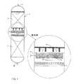
図面に関して説明する。なお、本発明の代替的な態様には、限定するわけではないが、図面に表される設計が含まれている。図1は、触媒粒子から構成される2つ触媒床2,3を備えた典型的な水素化処理リアクター1の概略図である。図1は、ミキシング・デバイスの典型的な配置を触媒床および他のリアクター・インターナルに対して規定しているものである。反応原系は、入口ノズル4を介してリアクターに導入される。そして、流体は、上部ディストリビューション・トレイ5に導入されるので、気体と液体とが触媒床2に導入される前にリアクターの断面領域に対して均一に分配されることになる。触媒床2は、スクリーンまたは触媒支持グリッド6上に配置されている。触媒自体の重い重量および触媒床を通る流体流れに起因する力によって、触媒スクリーンまたは触媒支持グリッドには大きな力が通常作用することになる。それゆえ、これらの力を吸収するには支持ビーム7が通常必要とされる。ミキシング・デバイス8は、触媒支持システム6,7の下方に配置されている。冷却流体ノズル9から冷却流体を加えてもよい。ミキサーの下方には、液体を広げると共に、ミキシング・デバイスから排出される噴流の速い速度を抑制するために、緩衝デバイス10を配置してもよい。ミキサーの下方には、気体および液体が次の触媒床3に入る前に気体および液体をリアクターの断面領域に対して均等に分配する第2ディストリビューション・トレイ11が配置されている。生成物は、出口ノズル12を介してリアクターから排出されることになる。
The drawings will be described. Note that alternative aspects of the invention include, but are not limited to, the design depicted in the drawings. FIG. 1 is a schematic diagram of a
触媒床を2つよりも多く設けてもよい。ミキシング・デバイス8の数は、リアクター内の触媒床の数をNとすると、典型的にはN―1となる。
More than two catalyst beds may be provided. The number of
図2〜図9は、本発明のミキシング・デバイスの別の構造を表している。これらの図は、代替的に本発明を特徴付けるために用いられているにすぎない。これらの図は、本明細書で開示された概念の範囲を限定するものではなく、構成を示す図として用いられている。また、それらの図は、本発明の概念の範囲を制限するものではない。図に表される相対寸法は、商業的な態様の寸法と同じはなく、また、等倍に拡大もしくは縮小した寸法でもない。 2-9 represent alternative structures of the mixing device of the present invention. These figures are merely used to characterize the present invention instead. These diagrams do not limit the scope of the concept disclosed in this specification, but are used as diagrams showing configurations. Moreover, these figures do not limit the scope of the concept of the present invention. The relative dimensions shown in the figures are not the same as the dimensions of the commercial embodiment, nor are the dimensions enlarged or reduced to the same magnification.
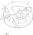
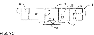
図2は、円形の上プレート13、円形の底プレート14および円筒形の側壁15から成るミキシング・ボックス8を分解切除した斜視図を模式的に示したものである。円筒形の側壁15は、リアクター内壁の一部を成していてもよく、または、リアクターよりも小さい直径を有した別個の壁であってもよい。好ましくは、ミキサーの高さが最小限度となるように、円筒形状の側壁15がリアクター直径と略同じとなっている。上プレート13の開口部16を除いて、ミキシング・ボックスでは、リアクター1内に実質的にリークが防止された流れ障害物(flow obstruction)が形成されている。円筒形の側壁の直径がリアクターの内径よりも小さい場合では、トレー・プレートまたは他の手段が、ミキシング・ボックス8とリアクター1の内壁との間を実質的にリークすることなく密封するのに用いられることになる。
FIG. 2 schematically shows a perspective view of the
冷却流体用の穿孔ディストリビューター17を介して、冷却流体がミキシング・ボックス8内に供給される。フロー・バッフル18,19,20がミキシング・ボックス内に設けられることによって、流れが混合されて高速の流れを生じる一連のミキシング・オリフィス21,22が形成される一方、流れが分割されて低速の流れを生じるフロー・チャンネル23,24が形成されている。フロー・バッフルは、開口部21,22,24を除いて、実質的にリークすることなく設けられているので、流体がミキシング・オリフィス21,22およびフロー・チャンネル23,24を確実に通るように流れることになる。底プレート14には、リアクターの中心線と同心の円形の出口開口部25が設けられている。この円形の開口部は、第3ミキシング・オリフィスであり、ミキサーの最後のミキシング・オリフィスとして機能している。
Cooling fluid is fed into the
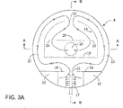
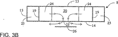
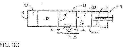
図3Aは、図2のミキサーを上から見た図である。図3Bは、図3Aを線A−Aに沿って切り取った断面図である。図3Cは、図3Aを線B−Bに沿って切り取った断面図である。図3Aおよび図3Bは、円形の開口部25と同心となるように円形の開口部25の下方に配置された円形の緩衝プレート(impingement plate)26を示している。
FIG. 3A is a top view of the mixer of FIG. 3B is a cross-sectional view taken along line AA of FIG. 3A. 3C is a cross-sectional view taken along line BB of FIG. 3A. 3A and 3B show a
図3A,3Bおよび3Cでは、デバイスを通過する流れが矢印で示されている。運転中では、触媒床2から排出される気体および液体は開口部16を通ってミキシング・ボックス内に流れ込む。低温の冷却流体がディストリビューター17から加えられる。そして、全てのプロセス・ストリームがミキシング・オリフィス21を通過するので、流速が速くなり、液体が気体内へと拡散することになる。その後、フロー・バッフル19によって、ストリームが流速のより低い2つのストリームに分けられる。そして、この2つのストリームは、対称的に設けられている2つのチャンネル23を流れて、次のミキシング・オリフィス22へと流れることになる。ミキシング・オリフィス22では、2つに分けられたストリームが速い流速で再度組み合わされることになる。ミキシング・オリフィス22を通過した後、フロー・バッフル20によって、ストリームが流速のより低い2つのストリームに再度分けられる。そして、2つのストリームは、対称的に設けられた2つの開口部/チャンネル24を通って中央開口部25へと流れることになる。その中央開口部25は第3ミキシング・オリフィスであり、分けられたストリームが速い流速で再度組み合わされることになる。そして、最終的には、緩衝プレート26によって、流体が半径方向外側へと向かってミキサーから排出されることになる。この緩衝プレートによって、ミキサーからディストリビューション・トレイ11へと速い速度の噴流が直接的に供給されることが防止されている。更に、緩衝プレート26によって、流体がディストリビューション・トレイ11に入る前に液体がリアクターの断面領域に良好に広がることになる。なお、ディストリビューション・トレイ11がないと、このような噴流は、ディストリビューション・トレイ11の液面を乱す場合があり、また、液体を同伴して運んでしまう場合がある。
In FIGS. 3A, 3B and 3C, the flow through the device is indicated by arrows. During operation, gases and liquids discharged from the
ミキシング・ボックス内の流速が比較的速いために、重力条件は、気相と液相との間の粘性力と比較して無視できる。それゆえ、ミキシング・ボックスが略水平に設けられている場合であっても、ミキシング・ボックス8内では相分離が顕著に生じることはない。
Due to the relatively high flow velocity in the mixing box, gravity conditions are negligible compared to the viscous force between the gas phase and the liquid phase. Therefore, even when the mixing box is provided substantially horizontally, phase separation does not occur remarkably in the
ミキシング・ボックス内のフロー・バッフルは種々の形状が考えられる。フロー・バッフルは、まっすぐなもの、湾曲したもの、折れ曲がったようなもの等であってもよい。フロー・バッフルは、完全に直角である必要はなく、フロー・バッフルが垂直的な要素を有していれば十分である。入口開口部16および出口開口部15も種々の形状が考えられ、図2および図3に示すような半扇形、長円形、円形、矩形または三角形などであってもよい。入口開口部および出口開口部の数は、双方とも1個またはそれ以上であってよい。ミキシング・ボックス自体の断面はいずれの形状であってもよい。ミキシング・ボックスの断面は、図2、図3A、図3Bおよび図3Cのミキサーに示すような円形であってよく、その他、三角形、矩形または多角形であってもよい。円形または角の多い多角形が好ましい。なぜなら、ベッセルの内側断面領域と同様の断面領域を有するようにミキシング・ボックスを設計することができるからである。
The flow baffle in the mixing box can have various shapes. The flow baffle may be straight, curved, bent or the like. The flow baffle does not have to be perfectly right, it is sufficient if the flow baffle has vertical elements. Various shapes are also conceivable for the
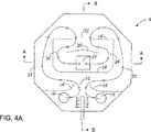
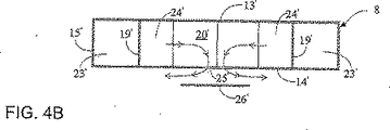
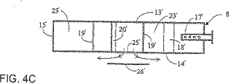
図4A、図4Bおよび図4Cにミキサーの代替的な設計の例を示す。ミキサーを流れる流路は矢印で示している。図4Aは、そのような代替的なミキシング・ボックス8を上から見た図である。図4Bは、図4Aを線A−Aに沿って切り取った断面図である。図4Cは、図4Aを線B−Bに沿って切り取った断面図である。ミキシング・ボックスは、上側壁13’、底側壁14’および側壁15’から構成されている。上側壁13’および底側壁14’は8角形の多角形の形状を有している。流体がミキシング・ボックス8へと流れ込むように、上側壁には2つの円形の開口部16’が設けられている。冷却流体用の穿孔ディストリビューター17’を用いることによって、開口部16’の下流側の上プレート13’と底プレート14’との間に冷却流体が加えられる。ミキシング・ボックスの内部には、湾曲したフロー・バッフル18’が配置されることによって、第1ミキシング・オリフィス21’が形成されている。また、ミキシング・ボックス内にはフロー・バッフル19’が設けられている。まず、ミキシング・オリフィス21’で分けられたストリームが2つのチャンネル23’を流れた後、その2つのストリームが第2ミキシング・オリフィス22’で再度1つのストリームへと組み合わされることになる。ミキシング・オリフィス21’に近接するフロー・バッフル19’のコーナーが湾曲するように形成されている一方、ミキシング・オリフィス22’に近接するフロー・バッフル19’のコーナーが折れ曲がるように形成されている。ミキシング・オリフィス22’の下流では、角度を成すように曲げられたフロー・バッフル20’が配置されている。フロー・バッフル20’は第2ミキシング・オリフィス22’から流れてくるストリームを分けて2つのフロー・チャンネル24’に流すようにしている。その後、分けられたストリームは、最後の第3ミキシング・オリフィス(正方形の出口開口部25’)で再度組み合わされることになる。出口開口部25’の下方には、緩衝プレート26’が配置されている。
Examples of alternative mixer designs are shown in FIGS. 4A, 4B and 4C. The flow path through the mixer is indicated by arrows. FIG. 4A is a top view of such an
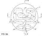
図2、図3A、図3B、図3C、図4A、図4Bおよび図4Cに示すミキサーは、3つのミキシング・オリフィス21,22および25(または21’,22’および25’)を有している。しかしながら、2またはそれよりも多くのミキシング・オリフィスを用いてミキシング・デバイスを作ることもできる。図5A、図5Bおよび図5Cは、4つのミキシング・オリフィスを備えたミキシング・ボックス8の例を示している。ミキサーを流れる流路は矢印で示している。図5Aは、ミキシング・ボックス8を上から見た図である。図5Bは、図5Aを線A−Aに沿って切り取った断面図である。図5Cは、図5Aを線B−Bに沿って切り取った断面図である。ミキシング・ボックスは、円形の上側壁13”、円形の底側壁14”および円筒形の側壁15”から構成されている。上側壁には1つの矩形開口部16”が設けられている。矩形開口部16”は、流体をミキシング・ボックス8へと流す通路として機能し、また、第1ミキシング・オリフィスとして機能する。ミキシング・ボックス8内には冷却流体が加えられないものの、ミキシング・オリフィス16”よりも上流側で冷却流体を加えてもよい。ミキシング・ボックスの内部にはフロー・バッフル27”が配置されており、ミキシング・オリフィス16”から流れてくるストリームを分けて2つのフロー・チャンネル28”に流すようにしている。また、ミキシング・ボックスの内部にはフロー・バッフル18”が配置されて第2ミキシング・オリフィス21”が形成されており、分けられた全ての再度組み合わされるようになっている。更に、ミキシング・ボックスの内部にはフロー・バッフル19”が配置されている。このフロー・バッフル19”はミキシング・オリフィス21”から流れてくるストリームを分けて2つのフロー・チャンネル23”に流すようにしている。その後、分けられた2つのストリームが、第3ミキシング・オリフィス22”で再度組み合わされることになる。ミキシング・オリフィス22”の下流側には、フロー・バッフル20”が配置されている。フロー・バッフル20”は、第3ミキシング・オリフィス22”から流れてくるストリームを分けて2つのフロー・チャンネル24”に流すようにしており、その後、分けられた全てのストリームが、最後のオリフィスである円形状の第4ミキシング・オリフィス25”で再度組み合わされることになる。ミキシング・オリフィス25”の下方には、円形の緩衝プレート26”が配置されている。
The mixer shown in FIGS. 2, 3A, 3B, 3C, 4A, 4B and 4C has three mixing
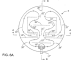
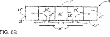
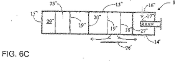
上述したように、流体をミキシング・ボックス8の内側からミキシング・ボックス8とディストリビューション・トレイ11との間のスペースへと導く出口開口部の個数、配置および形状はどのようなものであってもよい。図6A、図6Bおよび図6Cは、中心からずれた出口開口部25'''を含んだミキシング・ボックス8の例を示している。ミキサーを流れる流路は矢印で示している。図6Aは、中心からずれた出口開口部25'''を含むミキシング・ボックス8を上から見た図である。図6Bは、図6Aを線A−Aに沿って切り取った断面図である。図6Cは、図6Aを線B−Bに沿って切り取った断面図である。ミキシング・ボックスは、円形の上側壁13'''、円形の底側壁14'''および円筒形の側壁15'''から構成されている。上側壁には1つの円形の開口部16'''が設けられている。円形の開口部16'''は、流体をミキシング・ボックス8へと流す通路として機能し、また、第1ミキシング・オリフィスとして機能している。第1ミキシング・オリフィス16'''の下流側では、上側壁13'''と底側壁14'''との間に配置された冷却流体用穿孔ディストリビューター17'''を介して冷却流体を加えてもよい。ミキシング・ボックスの内部にはフロー・バッフル27'''が配置されており、ミキシング・オリフィス16'''から流れてくるストリームを分けて2つのフロー・チャンネル28'''に流れるようにしている。また、ミキシング・ボックスの内部にはフロー・バッフル18'''が配置されることによって第2ミキシング・オリフィス21'''が形成されており、分けられた全てのストリームが再度組み合わされるようになっている。ミキシング・ボックス内にはフロー・バッフル20'''が配置されており、ミキシング・オリフィス21'''からのストリームを2つのチャンネル24'''に流すようにしている。更に、ミキシング・ボックスの内部にはフロー・バッフル19'''が配置されている。このフロー・バッフル19'''は、チャンネル24'''を流れたストリームが再度組み合わされることになる第3ミキシング・オリフィス22'''を形成している。オリフィス22'''を通る流れ方向は、図2、図3A、図4Aおよび図5Aに示すミキシング・オリフィス22、22’および22''を通る流れ方向とは逆であることに留意されたい。ミキシング・オリフィス22'''を通過した全てのプロセス・ストリームは、出口開口部25'''に通じている2つのチャンネル23'''を通るように分けられることになる。液体を各々のチャンネル23'''へとより一様に分割して、ディストリビューション・トレイ11へと液体がより良く分配されるように、分割バッフル29'''をオプションとして用いてもよい。ストリームは、2つの矩形開口部25'''を介してミキシング・ボックスから排出されることになる。各々の出口開口部25'''の下方には、緩衝プレート26'''が配置されている。このようなミキサーは、ディストリビューション・トレイ11への液体の分配および広がりの点で上述の例よりも有利となっている。これは、出口開口部25'''がリアクターの中心に配置されておらず、流体がある側方のみから各開口部出口25'''へとアプローチすることになるからであり、また、ミキシング・オリフィス22'''の出口で液体が不均一に分割されることで開口部25'''の各々を通る液体の流速が変わり得るからである。
As described above, the number, arrangement, and shape of the outlet openings for guiding the fluid from the inside of the
上述したように、2またはそれよりも多くのミキシング・オリフィスを用いてミキシング・デバイスを作ることもできる。用いられるミキシング・オリフィスの数が多くなればなるほど、ミキサー全体の所定の圧力降下のために、ミキシング・ボックスの垂直方向高さをより大きくしなければならない。図7A、図7B、図7Cおよび図7Dは、2つのミキシング・オリフィス21*,22*を含んだミキシング・ボックス8の例を示している。図7Aは、ミキシング・ボックス8を上から見た図である。図7Bは、図7Aを線A−Aに沿って切り取った断面図である。図7Cは、図7Aを線B−Bに沿って切り取った断面図である。図7Dは、図7Aを線C−Cに沿って切り取った断面図である。ミキサーを流れる流路は矢印で示している。ミキシング・ボックスは、円形の上側壁13*、円形の底側壁14*および円筒形の側壁15*から構成されている。上側壁13*には、円形の入口開口部16*が2つ設けられている。入口開口部16*は、気体および液体を混合チャンバー8へと流すための通路として機能する。上端および下端にて開口するシリンダー30*が、上側壁13*とシリンダー30*との間でリークが実質的に生じないように各々の入口開口部16*に取り付けられたり、または、入口開口部16*を介して取り付けられたりしている。シリンダーの上縁にはV形ノッチ(V−notch)が設けられている。運転中では上側壁13*によって液体があるレベルに保持されており、V形ノッチによって入口開口部16*に入る液体流れが時間的に安定となる。従って、ミキサーに導入される液体の流速の変動が回避される。また、V形ノッチを有するシリンダー30*は、液体を各々の入口開口部16に分配する機能を有しており、その結果、各々の入口開口部における液体の流速が略同じとなる。チャンネル30*は円筒形状を有するように示されているものの、その断面が、長円形、矩形、三角形または多角形などの他の形状であってもよい。シリンダー30*の上縁はV形ノッチを有するように示しているものの、シリンダー30*の液体流れ用の開口部の形状は、スロット形または円形等の他の形状であってもよい。ミキシング・ボックス8内には冷却流体が加えられないものの、円形の入口開口部16*の上流で冷却流体を加えてもよい(図示せず)。ミキシング・ボックスの内部には、フロー・バッフル18*が2つ配置されており、第1ミキシング・オリフィス21*が形成されている。全てのプロセス・ストリームは、第1ミキシング・オリフィス21*を通過するように流れることになる。ミキシング・オリフィス21*からのストリームが分けられることで2つのフロー・チャンネル24*に流れることになるように、ミキシング・ボックス内にはフロー・バッフル20*が配置されている。また、ミキシング・ボックス内にはフロー・バッフル19*が配置されることによって第2ミキシング・オリフィス22*が形成されており、それによって、チャンネル24*を流れたストリームが再度組み合わされることになる。第2ミキシング・オリフィス22*を通過した全てのプロセス・ストリームは分けられて、矩形出口開口部25に各々つがっている2つのチャンネル23*を通るように流れることになる。各々のチャンネル23*を通るように液体をより一様に分割して、ディストリビューション・トレイ11へと液体がより良く分配されるように、分割バッフル29*をオプションとして用いてもよい。ストリームは、2つの矩形開口部25*を介してミキシング・ボックスから排出されることになる。各々の出口開口部25*の下方には、緩衝プレート26*が配置されている。図6A、図6Bおよび図6Cに示した上述のミキサーと同様に、本発明のミキサーは、ディストリビューション・トレイ11への液体の分配および広がりの点で有利である。これは、出口開口部25*がリアクターの中心に配置されておらず、流体がある側方のみから各開口部出口25*へとアプローチするからであり、また、第2ミキシング・オリフィス22*の出口で液体が不均一に分割されることで開口部25*の各々を通る液体の流速が変わり得るからである。なお、ミキシング・オリフィスが2つだけ用いられており、3つ以上用いられているわけではないので混合性能は僅かに減じられてしまい、このミキサーは上述のミキサーと比べて不利益となっている。ただし、このミキサーは幾つかの利点がある。ミキサーにはミキシング・オリフィスを2つしか設けていないので、所定の圧力降下に対して、ミキシング・オリフィスを3つ以上有するミキサーの場合よりもミキサーを通過する際の流速を速くすることができる。それゆえ、このミキサーでは、ミキシング・オリフィスおよびフロー・チャンネルの断面領域をより小さくすることができる。従って、ミキシング・オリフィスの必要な断面積がより小さくなり、ミキシング・オリフィスが3つ以上備わったミキサーの場合よりも高さを低くすることができる。中心のずれた2つの出口開口部25*を有する設計であって、ミキシング・オリフィス21*および22*を通過する流れが同じ方向となった設計では、ミキサーの高さを更に低くすることができる。従って、ミキサーの高さが低い非常にコンパクトな設計がもたらされるので、ミキシング・デバイスに用いられるスペースがほとんどないような直径の小さいリアクターに対して用いることができるようになる。リアクターの直径が小さくなればなるほど、ディストリビューション・トレイ11への液体の分配または広がりというものがあまり重要ではなくなる。なぜなら、ミキサーからの液体の広がりが乏しい場合、ディストリビューション・トレイ11に導入された液面の傾きは、直径が大きいリアクターの場合ほど重要とならなくなるからである。
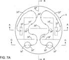
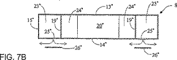
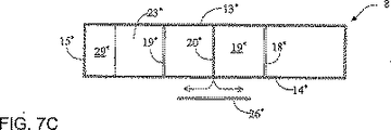
As mentioned above, a mixing device can be made using two or more mixing orifices. The greater the number of mixing orifices used, the greater the vertical height of the mixing box for a given pressure drop across the mixer. 7A, 7B, 7C, and 7D show an example of a
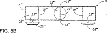
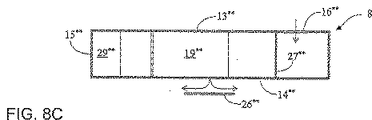
上述の例では、フロー・バッフルによって形成されるミキシング・オリフィスの断面領域は全て矩形状である。しかしながら、ミキシング・オリフィスの断面領域は、ミキシング・オリフィスにおいて全てのプロセス・ストリームが速い流速で組み合わされる(または混合される)ようなものであれば、いずれの形状であってよい。図8A、図8Bおよび図8Cは、断面領域が円形状の2つのミキシング・オリフィス16**,22**を含んだミキシング・ボックス8を示している。図8Aは、ミキシング・ボックス8を上から見た図を示している。図8Bは、図8Aを線A−Aに沿って切り取った断面図である。図8Cは、図8Aを線B−Bに沿って切り取った断面図である。ミキサーを流れる流路は矢印で示している。ミキシング・ボックスは、円形の上側壁13**、円形の底側壁14**および円筒形の側壁15**から構成されている。上側壁13**には、円形の入口開口部16**が1つ設けられている。入口開口部16**は、第1ミキシング・オリフィスとして機能し、また、流体を混合チャンバー8へと流すための通路として機能している。ミキシング・ボックス8内には冷却流体が加えられないものの、円形の入口開口部16**の上流で冷却流体を加えてもよい(図示せず)。ミキシング・オリフィス16**からのストリームが分けられて2つのフロー・チャンネル28**へと流れるように、ミキシング・ボックス内にはフロー・バッフル27**が配置されている。また、第2ミキシング・オリフィス22**が形成されるように、ミキシング・ボックス内に別のフロー・バッフル19**が配置されている。第2ミキシング・オリフィス22**ではチャンネル28**を流れた2つのストリームが再度組み合わされることになる。第2ミキシング・オリフィス22**を通過した全てのプロセス・ストリームは分けられることによって、矩形出口開口部25**に各々つがっている2つのチャンネル23**を流れることになる。液体を2つの各々のチャンネル23**へとより一様に分割して、ディストリビューション・トレイ11へと液体がより良く分配されるように、分割バッフル29**をオプションとして用いてもよい。ストリームは、2つの矩形開口部25**を介してミキシング・ボックスから排出されることになる。各々の出口開口部25**の下方には、緩衝プレート26**が配置されている。図7A、図7B、図7Cおよび図7Dに示した上述のミキサーと同様に、このミキサーは、ディストリビューション・トレイ11への液体の分配および広がりの点で有利である。また、このミキサーは、混合性能は僅かに減じられてしまうので、ミキシング・オリフィスを3つ以上の設計を有したミキサーの場合よりも不利益となっている。しかしながら、上述のミキサーと同様に、ミキサーの高さが低い非常にコンパクトな設計となるので、ミキシング・デバイスに用いられるスペースがほとんどないような直径の小さいリアクターに対して用いることができるようになっている。
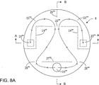
In the above example, the cross-sectional area of the mixing orifice formed by the flow baffle is all rectangular. However, the cross-sectional area of the mixing orifice may be any shape as long as all process streams are combined (or mixed) at a high flow rate at the mixing orifice. 8A, 8B and 8C show a
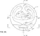
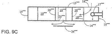
図9A、図9Bおよび図9Cは、図2、図3A、図3Bおよび図3Cのミキサーと同様のミキシング・オリフィスを3つ備えたミキシング・ボックスの例を示している。しかしながら、図9A、図9Bおよび図9Cに示されるミキサーは、入口開口部16***、フロー・バッフル19***,20***および冷却流体用ディストリビューター17***の点で変更されている。ミキサーを流れる流路は矢印で示している。図9Aは、ミキシング・ボックス8を上から見た図を示している。図9Bは、図9Aを線A−Aに沿って切り取った断面図である。図9Cは、図9Aを線B−Bに沿って切り取った断面図である。ミキシング・ボックスは、円形の上側壁13***、円形の底側壁14***および円筒形の側壁15***から構成されている。上側壁は扇形状に一部切り欠かれており、ミキシング・ボックス8に流体を入れるための入口開口部16***が形成されている。入口開口部16***の下流では、上プレート13***と底プレート14***との間に配置される冷却流体用ディストリビューター17***を介して冷却流体が加えられることになる。冷却流体用ディストリビューター17***は、どのような種類であってもよく、また、ディストリビューターから出る冷却流体の排出方向はどのような方向であってもよい。なお、図面では、流体の噴流が下側に向くようになったT形状の穿孔ディストリビューターが示されている。ミキシング・ボックス内にフロー・バッフル18***が2つ配置されることによって第1ミキシング・オリフィス21***が形成されている。第1ミキシング・オリフィス21***では、プロセス・ストリームの全てが速い流速で通過することになる。ミキシング・ボックス内には、湾曲したフロー・バッフル19***が配置されている。そのため、ミキシング・オリフィス21***からのストリームが分けられ、2つのチャンネル23***を通るように流れることになり、その後、分けられた2つのストリームが第2ミキシング・オリフィス22***で1つのストリームなるように組み合わされることになる。ミキシング・オリフィス22***の下流には、ステップ状のフロー・バッフル20***が配置されている。フロー・バッフル20***によって、第2ミキシング・オリフィス22***からのストリームが分けられることによって2つのフロー・チャンネル24***にストリームが流れることになり、その後、全てのストリームが、円形状の最後の第3ミキシング・オリフィスたる出口開口部25***で再度組み合わされることになる。出口開口部25***の下流には、緩衝プレート26***が配置されている。
9A, 9B and 9C show examples of mixing boxes with three mixing orifices similar to the mixers of FIGS. 2, 3A, 3B and 3C. However, the mixer shown in FIGS. 9A, 9B and 9C is modified in terms of inlet opening 16 *** ,
図1に戻って説明する。ミキシング・デバイスの全ての態様において、図2のミキシング・オリフィス21の場合のように水平方向流れを含んだミキシング・オリフィスを通過する流れの方向が、触媒スクリーンまたは触媒グリッド6の表面の下方で延在している支持ビーム7と平行となるように、ミキシング・ボックス8を方向付けることが好ましい。これによって、触媒床2の出口からミキシング・ボックス16の入口開口部に流れる流体の圧力降下が最小限度となる。かかる領域で圧力降下が大きいと、触媒床2を通過するフロー・パターンが不均一となってしまうので望ましくない。
Returning to FIG. In all aspects of the mixing device, the direction of flow through the mixing orifice, including horizontal flow, as in the case of the mixing
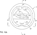
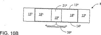
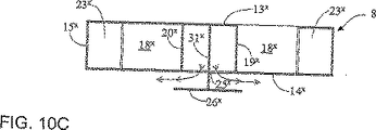
上述したミキサーの実施例の入口開口部16は、全てミキサーの側壁15に近接するように配置されている。このような入口開口部の配置は、上流側触媒床2の出口からミキサーの入口開口部16へと流れる気体および液体の上述したような圧力降下が増加する傾向を伴ってしまう。このような圧力降下を減じるために、入口開口部をリアクターの中心線付近に配置してもよい。図10A、図10Bおよび図10Cは、ミキサーおよびリアクターの中心付近に配置された扇形入口開口部16×を備えたミキシング・ボックス8の例を示している。図10Aは、ミキシング・ボックス8を上から見た図を示している。図10Bは、図10Aを線A−Aに沿って切り取った断面図である。図10Cは、図10Aを線B−Bに沿って切り取った断面図である。ミキサーを流れる流路は矢印で示している。ミキサーは2つのミキシング・オリフィスを有している。ミキシング・ボックスは、円形の上側壁13×、円形の底側壁14×および円筒形の側壁15×から構成されている。上側壁13×には、流体をミキシング・ボックス8へと流す通路として機能する扇形の入口開口部16×が設けられている。ミキシング・ボックス8内には冷却流体が加えられないものの、扇形入口開口部16×の上流にて冷却流体を加えてもよい(図示せず)。第1ミキシング・オリフィス21×および第2ミキシング・オリフィス22×が形成されるように、ミキシング・ボックス内には2つの半円形フロー・バッフル18×が配置されている。入口開口部16×を通過した全てのプロセス・ストリームは、第1ミキシング・オリフィス21×に入ることになる。第1ミキシング・オリフィス21×を通過したプロセス・ストリームは分けられて2つのチャンネル23×を流れることになる。チャンネル23×では気体および液体が円筒形の側壁15×を沿って第2ミキシング・オリフィス22×へと流れることになる。そして、第2ミキシング・オリフィス22×において、全てのプロセス・ストリームが速い流速で再度組み合わされる。第2ミキシング・オリフィスを通過したストリームを、正方形状出口開口部25×に入るに先立って速度のより遅い2つのストリームに分けるために、フロー・バッフル20×をオプションとして用いてもよい。ミキサー8の高さがより低いよりコンパクトな設計を達成するために、フロー・バッフル20×を取り除いて、その代わりに、出口開口部25×にフロー・バッフル31×をオプションとして配置してもよい。フロー・バッフル31×は、第2ミキシング・オリフィスを通過した流速の速いストリームが、出口開口部25×を通過する際に、ストリームがリアクターの一方の側だけに方向付けられることを防止する機能を有している。なお、リアクターの一方の側だけにストリームが方向付けられるならば、下方のディストリビューション・トレイへの液体の広がりが満足のいくものではなくなってしまう。出口開口部25×および入口開口部16×は、それを通過するストリームの流速が非常に遅いのでミキシング・オリフィスとは考えられない。出口開口部25×の下方には、緩衝プレート26×が配置されている。
All of the
再度、図1に戻って説明する。触媒支持システムは、触媒スクリーン6および支持ビーム7から構成されている。触媒支持システムとミキシング・デバイス8とは、図1では別個の構造を有するように示されている。しかしながら、本発明のミキシング・デバイスを、触媒支持システムと一体的に用いてもよい。
Again, returning to FIG. The catalyst support system is composed of a catalyst screen 6 and a support beam 7. The catalyst support system and the
ミキシング・ボックス自体は、そのミキシング・ボックスに及ぶ圧力降下に起因する力が吸収されるように、支持ビームまたは他の構造が必要とされ得る。そのような支持ビームまたを構造はいずれの図面にも示していないが、それらをミキシング・ボックスの上方または下方に配置したり、ミキシング・ボックスおよびフロー・バッフルと一体的に用いたりしてもよい。 The mixing box itself may require a support beam or other structure so that forces due to the pressure drop across the mixing box are absorbed. Such support beams or structures are not shown in any of the drawings, but they may be placed above or below the mixing box or used integrally with the mixing box and flow baffle. .
本発明のいずれの態様に対しても、小流量用排出穴を設けてもよい。ミキサーを構成するプレートは、1つのピースとして用いたり、または、幾つかのプレート・セクションを組み合わせた状態で用いたりしてもよい。通常は、幾つかの取外し可能なセクションがミキサーに用いられているために、点検および洗浄操作に際してアクセスが容易となっており、また、ミキシング・ボックスに手が届くようになっている。 For any aspect of the present invention, a small flow rate discharge hole may be provided. The plates that make up the mixer may be used as a single piece or in a combination of several plate sections. Typically, several removable sections are used in the mixer to facilitate access during inspection and cleaning operations, and to reach the mixing box.
フロー・チャンネルまたは開口部における2相ノースリップ流速は、液相と気相との間でスリップが存在しない場合の流速として規定される。このことは、液相の速度が気相の速度と同じであることを意味している。それゆえ、ノースリップ速度は、次の通りである: The two-phase no-slip flow rate in the flow channel or opening is defined as the flow rate when there is no slip between the liquid phase and the gas phase. This means that the liquid phase velocity is the same as the gas phase velocity. The no-slip speed is therefore as follows:
ここで、Qiは、チャンネルまたは開口部を通路する液体の体積流量であり、Qvは、チャンネルまたは開口部を通路する気体の体積流量であり、更に、Aは、チャンネルまたは開口部の断面積である。 Where Q i is the volumetric flow rate of the liquid passing through the channel or opening, Qv is the volumetric flow rate of the gas passing through the channel or opening, and A is the channel or opening breakage. It is an area.
ミキシング・ボックス8は典型的には略水平となっている。これは、リアクター1の一方の端部からもう一方の端部に至るまでのミキシング・ボックスの全体的な勾配(または傾き)が小さいことを意味している。ミキシング・ボックス8の直径は、リアクターの内径の50〜100%であることが典型的である。各ミキシング・オリフィスの断面領域は、ノースリップ速度が典型的には3〜15m/sとなるように選択されている。ミキシング・オリフィスの下流にて分けられた流れが含まれるチャンネルの断面領域は、ノースリップ流速の最大値が、対応するミキシング・オリフィスの流速の0.25〜1.00倍となるように典型的に選択されている。上プレートから緩衝プレートまでのミキサーの高さは、100mm(リアクター直径が小さい場合)〜500mm以上(リアクターの直径が大きい場合)であり、種々の値を取り得る。フロー・バッフル20および27の水平方向の幅は、典型的には上流側のミキシング・オリフィスの最大幅の1〜3倍である。
The
3種類の異なる商業的用途に対するミキサー設計の実施例を表1に示す。表1の3つの実施例の全ては、図2、図3A、図3Bおよび図3Cのミキサー設計に対応している。 Examples of mixer designs for three different commercial applications are shown in Table 1. All three examples in Table 1 correspond to the mixer designs of FIGS. 2, 3A, 3B, and 3C.
本発明に関しては、一般的には以下のことがいえる:
1つの要旨において、本発明は、縦型ベッセル内において並流で流れる気体と液体とを混合するミキシング・デバイスであって、直列に順次設けられた複数の混合シーケンス(mixing sequence)を気体および液体が通過する実質的に水平なミキシング・ボックスによって、気体および液体の流れを阻害するミキシング・デバイスに関する。なお、ある混合シーケンスが1つのミキシング・オリフィスとそれに続く1つのT字路として規定される。組み合わされた(または混合された)プロセス・ストリームが速い速度で通過することになる1つの開口部としてミキシング・オリフィスが規定される一方、あるオリフィスから流れてくる速度の速いストリームを速度がより低い2つのフロー・チャンネルに流れるように分けるストリーム・スプリット(stream split)としてT字路が規定されている。
In general, the following can be said with respect to the present invention:
In one aspect, the present invention is a mixing device for mixing a gas and a liquid that flow in parallel in a vertical vessel, wherein a plurality of mixing sequences sequentially provided in series are mixed with a gas and a liquid. Relates to a mixing device that inhibits the flow of gas and liquid by means of a substantially horizontal mixing box through which the gas flows. A mixing sequence is defined as one mixing orifice followed by one T-junction. A mixing orifice is defined as one opening through which the combined (or mixed) process streams will pass at a high speed, while a high speed stream flowing from one orifice is at a lower speed A T-junction is defined as a stream split that divides to flow into two flow channels.
本発明のミキシング・デバイスにおいて、「実質的に水平な」ミキシング・ボックスというものは、ベッセルの一方の端部からもう一方の端部に至るまでのミキシング・ボックスの全体的な勾配が20%未満となっており、水平面と成す角度が最大11.5°となっているミキシング・ボックスとして規定されるものである。ミキシング・ボックスの個々のセグメントは、ベッセルの一方の端部からもう一方の端部に至るまでの全体的な勾配が20%未満(11.5°に相当する)であれば、より大きい勾配を有することができる。 In the mixing device of the present invention, a “substantially horizontal” mixing box means that the overall gradient of the mixing box from one end of the vessel to the other is less than 20% And is defined as a mixing box having a maximum angle of 11.5 ° with the horizontal plane. Individual segments of the mixing box have a greater slope if the overall slope from one end of the vessel to the other is less than 20% (corresponding to 11.5 °). Can have.
更に、ベッセル壁に対して垂直な面において実質的に水平に設けられたミキシング・ボックスの断面積は、ベッセルの内側断面積の25%〜100%である。ミキシング・ボックスの断面積が、リアクター断面積の100%未満である場合、ミキシング・ボックスとベッセル壁との間の面積がプレートまたは他の手段で封止されることによって、ミキシング・ボックスとベッセル壁との間を実質的に流体が漏れることのないように連結することができる。 Furthermore, the cross-sectional area of the mixing box provided substantially horizontally in a plane perpendicular to the vessel wall is 25% to 100% of the inner cross-sectional area of the vessel. If the cross-sectional area of the mixing box is less than 100% of the cross-sectional area of the reactor, the area between the mixing box and the vessel wall is sealed with a plate or other means so that the mixing box and the vessel wall Can be connected so that fluid does not substantially leak.
第1ミキシング・オリフィスの上流または2つのミキシング・オリフィスの間においてパイプもしくはディストリビューターを介して冷却流体を加えることによって、プロセス・ストリームを冷却してもよい。 The process stream may be cooled by adding cooling fluid through a pipe or distributor upstream of the first mixing orifice or between the two mixing orifices.
ミキシング・ボックスは、少なくとも2つのミキシング・オリフィスを有して成る。 The mixing box comprises at least two mixing orifices.
ミキシング・オリフィスでのノースリップ2相流速は、3m/s〜15m/sである。T字路の下流側にて流れが分けられることになるチャンネルでのノースリップ2相流速の最大値は、流れが組み合わされる(または混合される)上流側のミキシング・オリフィスでのノースリップ2相流速の値の25%よりも大きい値である。T字路の下流側にて流れ分けられるチャンネルでのノースリップ2相流速の最小値は、流れが組み合わされる(または混合される)上流側のミキシング・オリフィスでのノースリップ2相流速の値の100%よりも小さい。 The no-slip two-phase flow velocity at the mixing orifice is 3 m / s to 15 m / s. The maximum no-slip two-phase flow velocity in the channel where the flow will be split downstream of the T-junction is the no-slip two-phase at the upstream mixing orifice where the flows are combined (or mixed) It is a value larger than 25% of the value of the flow velocity. The minimum value of the no-slip two-phase flow velocity in the channel that is divided downstream of the T-junction is the value of the no-slip two-phase flow velocity value at the upstream mixing orifice where the flows are combined (or mixed). Less than 100%.
リアクター・ベッセルは、気体と液体とが並流で下方向へと流れる縦型水素化処理リアクターであって、水素化処理触媒の存在下で炭化水素と水素リッチガスとが反応するリアクターであってよい。 The reactor vessel may be a vertical hydroprocessing reactor in which a gas and a liquid flow in the downward direction in parallel flow, and may be a reactor in which a hydrocarbon and a hydrogen-rich gas react in the presence of a hydroprocessing catalyst. .
以上、本発明の種々の態様について説明してきた。なお、特許請求の範囲に記載された発明から逸脱することなく、種々の変更および修正が考えられる。 In the above, various aspects of the present invention have been described. Various changes and modifications can be made without departing from the invention described in the claims.
従って、例えば、ミキシング・オリフィスまたは通路のいずれかを、共通の壁で2つの以上の隣接するオリフィスまたは通路へと分割してもよい。しかしながら、現在、各々のミキシング・オリフィスまたは通路を分けない状態の方が、混合性能および防汚の点で最も良い結果が得られるものと考えられている。 Thus, for example, any mixing orifice or passage may be divided by a common wall into two or more adjacent orifices or passages. However, it is currently believed that the best results are achieved in terms of mixing performance and antifouling when each mixing orifice or passage is not separated.
例えば、翼部、バッフルおよびグリッド等の乱れ発生手段をミキシング・オリフィスまたは通路の上流またはミキシング・オリフィス自体または通路自体に設けてもよい。 For example, turbulence generating means such as wings, baffles and grids may be provided upstream of the mixing orifice or passage or in the mixing orifice itself or the passage itself.
Claims (38)
該ミキシング・デバイスには、該上方触媒床から該下方触媒床へと又は該下方触媒床から該上方触媒床へと該気体および該液体が流れるように該ミキシング・デバイス内を通る流路が規定されており、
該流路が、
− 該ミキシング・デバイスの少なくとも1つの入口開口部、
− 該ミキシング・デバイスの少なくとも1つの出口開口部、
− 該流路に沿うように順次配置された第1ミキシング・オリフィスおよび少なくとも1つの第2ミキシング・オリフィス、ならびに
−ミキシング・デバイスの垂直方向の寸法ができる限り小さくなるように、該少なくとも1つの入口開口部と該少なくとも1つの出口開口部との間で延在する実質的に水平な流路セクション
を有して成り、
該第1ミキシング・オリフィスおよび該少なくとも1つの第2ミキシング・オリフィスの各々が単一の開口部を成し、液体と気体との混合流れの実質的に全体が該第1ミキシング・オリフィスおよび該第2ミキシング・オリフィスの各々を通るようになっており、
該第1ミキシング・オリフィスおよび該第2ミキシング・オリフィスには、該リアクターの少なくとも1つの操作段階の間、液体の気体中への拡散および/または気体の液体中への拡散にとって十分となる「ミキシング・オリフィスにおける混合流れのノースリップ2相流速が3m/s〜15m/s」となるように、該混合流れの流量に対して流通領域が設けられており、また
該実質的に水平な流路セクションは、該入口開口部付近から該出口開口部付近まで延在しており、
ミキシング・オリフィスの下流側の前記流路に拡張領域流路セクションが設けられており、
該拡張領域流路セクションでのノースリップ2相流速が、対応するミキシング・オリフィスを通過する際のノースリップ2相流速よりも実質的に遅くなっており、それによって、該拡張領域流路セクションの該流れのホールド時間が増加して伝熱および物質移動がもたらされるような断面領域を該拡張領域流路セクションが有しており、また
前記拡張領域流路セクションは、前記混合流れの全体を少なくとも2つの別個の2相流れ若しくはストリームに分けるためのフロー・チャンネルを少なくとも2つ有して成り、
少なくとも2つの別個の2相ストリームの各々のノースリップ2相流速が、対応するミキシング・オリフィスを通過する際のノースリップ2相流速よりも実質的に遅くなっており、それによって、少なくとも2つのチャンネルでのホールド時間が増加して伝熱および物質移動がもたらされるような組み合わされた断面領域を該少なくとも2つのチャンネルが有している、ミキシング・デバイス。A mixing device used in a catalytic reactor and disposed between an upper catalyst bed and a lower catalyst bed of the catalytic reactor, wherein the mixing device is disposed in the reactor vessel so as to pass through the catalyst beds arranged one above the other. A mixing device for mixing liquid and gas or vapors flowing in parallel,
The mixing device defines a flow path through the mixing device such that the gas and the liquid flow from the upper catalyst bed to the lower catalyst bed or from the lower catalyst bed to the upper catalyst bed. Has been
The flow path is
-At least one inlet opening of the mixing device;
-At least one outlet opening of the mixing device;
A first mixing orifice and at least one second mixing orifice arranged sequentially along the flow path; and the at least one inlet so that the vertical dimension of the mixing device is as small as possible Comprising a substantially horizontal channel section extending between the opening and the at least one outlet opening;
Each of the first mixing orifice and the at least one second mixing orifice forms a single opening, and substantially the entire mixed flow of liquid and gas is the first mixing orifice and the second mixing orifice. It is adapted to pass through each of the 2 mixing orifices,
The first mixing orifice and the second mixing orifice include a “mixing” that is sufficient for diffusion of the liquid into the gas and / or diffusion of the gas into the liquid during at least one operational phase of the reactor. A flow region is provided for the flow rate of the mixed flow so that the no-slip two-phase flow velocity of the mixed flow at the orifice is 3 m / s to 15 m / s, and the substantially horizontal flow path A section extends from near the inlet opening to near the outlet opening ;
An expansion zone channel section is provided in the channel downstream of the mixing orifice,
The no-slip two-phase flow rate in the expansion region channel section is substantially slower than the no-slip two-phase flow rate when passing through the corresponding mixing orifice, thereby The extended region flow path section has a cross-sectional area such that the flow hold time is increased to provide heat transfer and mass transfer; and
The extended region channel section comprises at least two flow channels for dividing the entire mixed flow into at least two separate two-phase flows or streams;
The no-slip two-phase flow rate of each of the at least two separate two-phase streams is substantially slower than the no-slip two-phase flow rate through the corresponding mixing orifice, thereby providing at least two channels A mixing device , wherein the at least two channels have a combined cross-sectional area that increases heat hold time and results in heat transfer and mass transfer .
ミキシング・ボックスの個々のセグメントは、該ミキシング・デバイスの全体的な勾配が該11.5°に対応する該20%より大きくならない状態において、より大きい勾配を有している、請求項1〜6のいずれかに記載のミキシング・デバイス。The overall slope of the mixing device from one side of the mixing device to the other is less than 20%, corresponding to a maximum angle of 11.5 ° with the horizontal plane, and
The individual segments of the mixing box have a greater slope, with the overall slope of the mixing device not greater than the 20% corresponding to the 11.5 °. A mixing device according to any one of the above.
該ミキシング・デバイスには、該上方触媒床から該下方触媒床へと又は該下方触媒床から該上方触媒床へと流れるように該気体および該液体が該ミキシング・デバイス内を通る流路が規定されており、
− 少なくとも1つの入口開口部が設けられた上側壁、
− 少なくも1つの出口開口部が設けられた底側壁、
− 該上側壁と該底側壁との間で閉空間が規定されるように該上側壁の周縁部と該底側部の周縁部との間で延在する側壁、ならびに
− 該上側壁、該底側壁および該側壁と共に該流路を規定するように該上側壁と該底側壁との間で延在する内部パーティション壁
を有して成り、
該パーティション壁が、更に、該流路に沿って順次配置される第1ミキシング・オリフィスおよび少なくとも1つの第2ミキシング・オリフィスの各々が単一の開口部を成し、それによって、液体と気体との混合流れの実質的に全体が第1ミキシング・オリフィスおよび第2ミキシング・オリフィスの各々を通るようになっており、
該リアクターの少なくとも1つの操作段階の間、液体の気体中への拡散および/または気体の液体中への拡散にとって十分となる「ミキシング・オリフィスにおける混合流れのノースリップ2相流速が3m/s〜15m/s」となるように、該混合流れの流量に対して流通領域が第1ミキシング・オリフィスおよび第2ミキシング・オリフィスに設けられており、また
ミキシング・デバイスの垂直方向寸法ができる限り小さくなるように、該内部パーティション壁が、該上側壁、該底側壁および該側壁と共に、該少なくとも1つの入口開口部と該少なくとも1つの出口開口部との間で延在する実質的に水平な流路セクションを規定しており、該実質的に水平な流路セクションが該入口開口部付近から該出口開口部付近まで延在しており、
前記パーティション壁は、ミキシング・オリフィスの下流側の前記流路に拡張領域流路セクションが設けられるように構成されており、
該拡張領域流路セクションにおけるノースリップ2相流速が、対応するミキシング・オリフィスを通過する際のノースリップ2相流速よりも実質的に遅くなっており、それによって、該拡張領域流路セクションにおける該流れのホールド時間が増加して伝熱および物質移動がもたらされる断面領域を該拡張領域流路セクションは有しており、また
前記拡張領域流路セクションは、前記混合流れ全体を少なくとも2つの別個の2相流れ若しくはストリームに分けるためのフロー・チャンネルを少なくとも2つ有して成り、
少なくとも2つの別個の2相ストリームの各々のノースリップ2相流速が、対応するミキシング・オリフィスを通過する際のノースリップ2相流速よりも実質的に遅くなっており、それによって、少なくとも2つのチャンネルでのホールド時間が増加して伝熱および物質移動がもたらされるような組み合わされた断面領域を少なくとも2つのチャンネルが有している、ミキシング・デバイス。A mixing device used in a catalytic reactor and disposed between an upper catalyst bed and a lower catalyst bed of the catalytic reactor, wherein the reactor substantially passes through the catalyst beds disposed one above the other. A mixing device for mixing gas or vapor and liquid flowing in parallel in a vertical vessel,
The mixing device defines a flow path for the gas and liquid to pass through the mixing device such that the gas flows from the upper catalyst bed to the lower catalyst bed or from the lower catalyst bed to the upper catalyst bed. Has been
-An upper wall provided with at least one inlet opening;
-A bottom sidewall provided with at least one outlet opening,
-A side wall extending between a peripheral edge of the upper side wall and a peripheral edge of the bottom side so that a closed space is defined between the upper side wall and the bottom side wall; and-the upper side wall, A bottom side wall and an inner partition wall extending between the top side wall and the bottom side wall to define the flow path along with the side wall;
The partition wall further comprises a first mixing orifice and at least one second mixing orifice , which are sequentially arranged along the flow path, each forming a single opening, whereby liquid and gas Substantially all of the mixing flow of the first and second mixing orifices passes through each of the first and second mixing orifices;
“At least one operational phase of the reactor is sufficient for diffusion of the liquid into the gas and / or diffusion of the gas into the liquid“ no-slip two-phase flow rate of the mixed flow at the mixing orifice is from 3 m / s 15 m / s ", flow areas are provided in the first mixing orifice and the second mixing orifice for the flow rate of the mixed flow, and the vertical dimension of the mixing device is as small as possible. As such, the inner partition wall, together with the top wall, the bottom wall and the side wall, extends between the at least one inlet opening and the at least one outlet opening. Defining a section, the substantially horizontal channel section extending from near the inlet opening to near the outlet opening ;
The partition wall is configured such that an extended region channel section is provided in the channel downstream of the mixing orifice;
The no-slip two-phase flow rate in the expansion region channel section is substantially slower than the no-slip two-phase flow rate through the corresponding mixing orifice, thereby The expanded area channel section has a cross-sectional area in which flow hold time is increased resulting in heat transfer and mass transfer; and
The expansion zone channel section comprises at least two flow channels for dividing the entire mixed flow into at least two separate two-phase flows or streams;
The no-slip two-phase flow rate of each of the at least two separate two-phase streams is substantially slower than the no-slip two-phase flow rate through the corresponding mixing orifice, thereby providing at least two channels A mixing device wherein the at least two channels have a combined cross-sectional area such that the hold time at the substrate increases heat transfer and mass transfer .
前記上側壁または前記底側壁の周縁部の第1ポイントと、その個々の第1ポイントからそれぞれ最も離れた前記上側壁または前記底側壁の周縁部の個々のポイントとの間で算出される前記ミキシング・デバイスの全体的な勾配は、水平面との間で成す角度が最大11.5°に対応する20%未満である、触媒リアクター。A catalytic reactor comprising an upper catalyst bed above the lower catalyst bed and provided with a mixing device according to any of claims 11 to 21, comprising:
The mixing calculated between a first point of a peripheral edge of the upper side wall or the bottom side wall and an individual point of the peripheral edge of the upper side wall or the bottom side wall respectively farthest from the respective first point. A catalytic reactor in which the overall slope of the device is less than 20%, corresponding to a maximum of 11.5 ° with respect to the horizontal plane.
− 液体と気体との混合流れの全体を単一の開口部に通過させ、前記リアクターの少なくとも1つの操作段階の間で該単一の開口部におけるノースリップ2相流速が液体の気体中への拡散および/または気体の液体中への拡散にとって十分となる3m/s〜15m/sとなるように、液体と気体との混合流れの全体の断面領域を狭小化させる第1狭小工程、
− 引き続いて、該断面領域を拡張する第1拡張工程、
− 引き続いて、液体と気体との混合流れの全体を単一の開口部に通過させ、該単一の開口部におけるノースリップ2相流速が3m/s〜15m/sとなるように、液体の気体中への拡散および/または気体の液体中への拡散にとって十分となるように、前記断面領域を狭小化させる第2狭小工程、ならびに
− 全流路のうちの実質的な長さに沿って延在する流路セクションであって、少なくとも1つの実質的に水平な流路セクションを有して成る流路へと前記混合流れを導く工程
を含んで成り、
前記断面領域を拡張する拡張工程には、前記混合流れを、少なくとも2つの別個の2相流れまたはストリームに分けることが含まれる、方法。A method of mixing a gas or vapor and a liquid flowing in a catalytic reactor in parallel flow between an upper catalyst bed and a lower catalyst bed of the catalyst reactor,
Passing the entire mixed stream of liquid and gas through a single opening, so that during at least one operating stage of the reactor the no-slip two-phase flow rate at the single opening is into the liquid gas A first narrowing step for narrowing the entire cross-sectional area of the mixed flow of liquid and gas so as to be 3 m / s to 15 m / s, which is sufficient for diffusion and / or diffusion of the gas into the liquid ;
-A first expansion step for subsequently expanding the cross-sectional area;
-The liquid and gas mixture flow is subsequently passed through a single opening, so that the no-slip two-phase flow velocity in the single opening is between 3 m / s and 15 m / s. A second narrowing step for narrowing the cross-sectional area so that it is sufficient for diffusion into the gas and / or diffusion of the gas into the liquid, and-along a substantial length of the total flow path a extending flow path section, Ri comprises the step of directing said mixture flows into the flow path comprising at least one substantially horizontal flow path section,
The method of expanding the cross-sectional area includes dividing the mixed flow into at least two separate two-phase flows or streams .
Applications Claiming Priority (3)
| Application Number | Priority Date | Filing Date | Title |
|---|---|---|---|
| DKPA200201718 | 2002-11-08 | ||
| DKPA200201718 | 2002-11-08 | ||
| PCT/DK2003/000757 WO2004041426A1 (en) | 2002-11-08 | 2003-11-05 | Mixing device for two-phase concurrent vessels |
Publications (2)
| Publication Number | Publication Date |
|---|---|
| JP2006505388A JP2006505388A (en) | 2006-02-16 |
| JP4741237B2 true JP4741237B2 (en) | 2011-08-03 |
Family
ID=32309253
Family Applications (1)
| Application Number | Title | Priority Date | Filing Date |
|---|---|---|---|
| JP2004548687A Expired - Lifetime JP4741237B2 (en) | 2002-11-08 | 2003-11-05 | Mixing device used for two-phase parallel flow vessel |
Country Status (6)
| Country | Link |
|---|---|
| EP (1) | EP1562697A1 (en) |
| JP (1) | JP4741237B2 (en) |
| CN (1) | CN100355494C (en) |
| AU (1) | AU2003277837A1 (en) |
| EA (1) | EA007052B1 (en) |
| WO (1) | WO2004041426A1 (en) |
Families Citing this family (20)
| Publication number | Priority date | Publication date | Assignee | Title |
|---|---|---|---|---|
| DE102007034715A1 (en) * | 2007-07-23 | 2009-01-29 | Evonik Röhm Gmbh | Reactor for the production of hydrogen cyanide by the Andrussow method |
| FR2952835B1 (en) * | 2009-11-20 | 2011-12-09 | Inst Francais Du Petrole | COMPACT DEVICE FOR MIXING FLUIDS IN A DOWNFLOW REACTOR |
| ES2479465T3 (en) * | 2010-04-23 | 2014-07-24 | Neste Oil Oyj | Power distribution device for a separation column |
| US8841495B2 (en) * | 2011-04-18 | 2014-09-23 | Gas Technology Institute | Bubbling bed catalytic hydropyrolysis process utilizing larger catalyst particles and smaller biomass particles featuring an anti-slugging reactor |
| FR2989006B1 (en) | 2012-04-04 | 2016-11-18 | Ifp Energies Now | CATALYTIC REACTOR WITH TEMPERATURE DEVICE PROVIDED WITH TANGENTIAL INJECTION OF A TEMPERED FLUID |
| CN105188902B (en) * | 2013-02-05 | 2018-09-25 | 托普索公司 | Multi-bed reactor with mixing equipment |
| US9359563B2 (en) | 2013-04-15 | 2016-06-07 | Uop Llc | Hydroprocessing initializing process and apparatus relating thereto |
| FR3034323B1 (en) * | 2015-04-01 | 2017-03-17 | Ifp Energies Now | MIXING AND DISPENSING DEVICE WITH MIXING AND EXCHANGE ZONES |
| FR3034324B1 (en) * | 2015-04-01 | 2017-03-17 | Ifp Energies Now | MIXING AND DISPENSING DEVICE COMPRISING A DISPENSING TRAY WITH PERIPHERAL OPENINGS |
| FR3034325B1 (en) * | 2015-04-01 | 2017-03-17 | Ifp Energies Now | COMPACT DISPOSITION OF MIXING AND COMBINED DISTRIBUTION |
| US9828897B2 (en) * | 2015-04-30 | 2017-11-28 | Faurecia Emissions Control Technologies Usa, Llc | Mixer for a vehicle exhaust system |
| FR3050658B1 (en) * | 2016-04-29 | 2018-04-20 | IFP Energies Nouvelles | DEVICE FOR MIXING AND DISPENSING WITH MIXING AND EXCHANGE ZONES AND DEFLECTORS. |
| FR3078636B1 (en) * | 2018-03-07 | 2020-03-13 | IFP Energies Nouvelles | MIXING DEVICE LOCATED ABOVE THE DISTRIBUTION AREA |
| CN111013495B (en) * | 2018-10-10 | 2022-03-11 | 中国石油化工股份有限公司 | Intersegment feeding structure of multi-section fixed bed reactor, multi-section fixed bed reactor and application of intersegment feeding structure |
| US10589244B1 (en) * | 2019-02-07 | 2020-03-17 | Uop Llc | Hydroprocessing reactor internals having reduced height |
| US11298670B2 (en) * | 2020-04-24 | 2022-04-12 | Uop Llc | Compact quench zone reactor internals |
| CN111659320B (en) * | 2020-06-15 | 2022-08-05 | 中国石油化工股份有限公司 | Hydrogen cooling box for hydrogenation reactor |
| US11207650B1 (en) * | 2020-09-30 | 2021-12-28 | Uop Llc | Hydroprocessing reactor internals having reduced height |
| CN112691568A (en) * | 2021-01-12 | 2021-04-23 | 陕西青叶生物科技有限公司 | Mixing stirrer for preparing hypochlorous acid solution |
| CN113636683B (en) * | 2021-08-18 | 2023-03-21 | 塔里木大学 | Inorganic chemistry experiment sewage treatment plant |
Family Cites Families (6)
| Publication number | Priority date | Publication date | Assignee | Title |
|---|---|---|---|---|
| US3592612A (en) * | 1966-11-02 | 1971-07-13 | John H Ballard | Two-stage apparatus for mixing fluids in concurrent downflow relationship |
| US3705016A (en) * | 1970-11-20 | 1972-12-05 | Universal Oil Prod Co | Fluid-solids contacting chamber |
| US4233269A (en) * | 1978-11-09 | 1980-11-11 | Exxon Research & Engineering Co. | Gas liquid distributor |
| US4669890A (en) * | 1985-03-25 | 1987-06-02 | Uop Inc. | Mixing device for vertical flow fluid-solid contacting |
| US5690896A (en) * | 1995-05-05 | 1997-11-25 | Chevron U.S.A. Inc. | Distributor assembly for multi-bed down-flow catalytic reactors |
| JP3676437B2 (en) * | 1995-07-10 | 2005-07-27 | 新日本石油株式会社 | Reaction tower |
-
2003
- 2003-11-05 WO PCT/DK2003/000757 patent/WO2004041426A1/en not_active Ceased
- 2003-11-05 JP JP2004548687A patent/JP4741237B2/en not_active Expired - Lifetime
- 2003-11-05 EP EP03769259A patent/EP1562697A1/en not_active Ceased
- 2003-11-05 CN CNB2003801073442A patent/CN100355494C/en not_active Expired - Lifetime
- 2003-11-05 EA EA200500791A patent/EA007052B1/en unknown
- 2003-11-05 AU AU2003277837A patent/AU2003277837A1/en not_active Abandoned
Also Published As
| Publication number | Publication date |
|---|---|
| CN100355494C (en) | 2007-12-19 |
| AU2003277837A1 (en) | 2004-06-07 |
| EP1562697A1 (en) | 2005-08-17 |
| WO2004041426A1 (en) | 2004-05-21 |
| JP2006505388A (en) | 2006-02-16 |
| CN1732040A (en) | 2006-02-08 |
| EA200500791A1 (en) | 2005-12-29 |
| EA007052B1 (en) | 2006-06-30 |
Similar Documents
| Publication | Publication Date | Title |
|---|---|---|
| JP4741237B2 (en) | Mixing device used for two-phase parallel flow vessel | |
| JP6342177B2 (en) | Mixing device for two-phase co-current vessel with tangential inlet | |
| US7276215B2 (en) | Mixing device for two-phase concurrent vessels | |
| US9452411B2 (en) | Device for injecting and mixing fluids in a downward-flow reactor | |
| US8372354B2 (en) | Multiphase contact and distribution apparatus for hydroprocessing | |
| US7506861B2 (en) | Distribution device for two-phase concurrent downflow vessels | |
| US7052654B2 (en) | Multiphase mixing device with staged gas introduction | |
| RU2559483C2 (en) | Device for multiphase contact and distribution for hydraulic compaction | |
| CA2595478C (en) | Distribution device for two-phase concurrent downflow vessels | |
| MX2008013006A (en) | A fluid distribution tray and method for the distribution of a highly dispersed fluid across a bed of contact material. | |
| JP2004307504A (en) | Improved mixing and dispensing apparatus for gas and liquid phases fed to a granular bed | |
| CN111065452B (en) | Method and apparatus for fluid contact in a downflow vessel | |
| US20190076806A1 (en) | Methods and apparatus for fluid contacting in a downflow vessel | |
| EP3658267B1 (en) | Methods for fluid contacting in a downflow vessel | |
| TW201628710A (en) | Compact fluid mixing device | |
| CN111344056A (en) | Method and apparatus for fluid contact in a downflow vessel |
Legal Events
| Date | Code | Title | Description |
|---|---|---|---|
| A621 | Written request for application examination |
Free format text: JAPANESE INTERMEDIATE CODE: A621 Effective date: 20061102 |
|
| A131 | Notification of reasons for refusal |
Free format text: JAPANESE INTERMEDIATE CODE: A131 Effective date: 20091006 |
|
| A601 | Written request for extension of time |
Free format text: JAPANESE INTERMEDIATE CODE: A601 Effective date: 20091225 |
|
| A602 | Written permission of extension of time |
Free format text: JAPANESE INTERMEDIATE CODE: A602 Effective date: 20100107 |
|
| A521 | Request for written amendment filed |
Free format text: JAPANESE INTERMEDIATE CODE: A523 Effective date: 20100204 |
|
| A02 | Decision of refusal |
Free format text: JAPANESE INTERMEDIATE CODE: A02 Effective date: 20100608 |
|
| A521 | Request for written amendment filed |
Free format text: JAPANESE INTERMEDIATE CODE: A523 Effective date: 20101007 |
|
| A911 | Transfer to examiner for re-examination before appeal (zenchi) |
Free format text: JAPANESE INTERMEDIATE CODE: A911 Effective date: 20101125 |
|
| TRDD | Decision of grant or rejection written | ||
| A01 | Written decision to grant a patent or to grant a registration (utility model) |
Free format text: JAPANESE INTERMEDIATE CODE: A01 Effective date: 20110405 |
|
| A61 | First payment of annual fees (during grant procedure) |
Free format text: JAPANESE INTERMEDIATE CODE: A61 Effective date: 20110506 |
|
| R150 | Certificate of patent or registration of utility model |
Ref document number: 4741237 Country of ref document: JP Free format text: JAPANESE INTERMEDIATE CODE: R150 Free format text: JAPANESE INTERMEDIATE CODE: R150 |
|
| FPAY | Renewal fee payment (event date is renewal date of database) |
Free format text: PAYMENT UNTIL: 20140513 Year of fee payment: 3 |
|
| R250 | Receipt of annual fees |
Free format text: JAPANESE INTERMEDIATE CODE: R250 |
|
| R250 | Receipt of annual fees |
Free format text: JAPANESE INTERMEDIATE CODE: R250 |
|
| R250 | Receipt of annual fees |
Free format text: JAPANESE INTERMEDIATE CODE: R250 |
|
| R250 | Receipt of annual fees |
Free format text: JAPANESE INTERMEDIATE CODE: R250 |
|
| R250 | Receipt of annual fees |
Free format text: JAPANESE INTERMEDIATE CODE: R250 |
|
| R250 | Receipt of annual fees |
Free format text: JAPANESE INTERMEDIATE CODE: R250 |
|
| R250 | Receipt of annual fees |
Free format text: JAPANESE INTERMEDIATE CODE: R250 |
|
| R250 | Receipt of annual fees |
Free format text: JAPANESE INTERMEDIATE CODE: R250 |
|
| R250 | Receipt of annual fees |
Free format text: JAPANESE INTERMEDIATE CODE: R250 |
|
| R250 | Receipt of annual fees |
Free format text: JAPANESE INTERMEDIATE CODE: R250 |
|
| EXPY | Cancellation because of completion of term |