JP4740605B2 - Gas control rotary movement device and gas control actuator - Google Patents
Gas control rotary movement device and gas control actuator Download PDFInfo
- Publication number
- JP4740605B2 JP4740605B2 JP2005020947A JP2005020947A JP4740605B2 JP 4740605 B2 JP4740605 B2 JP 4740605B2 JP 2005020947 A JP2005020947 A JP 2005020947A JP 2005020947 A JP2005020947 A JP 2005020947A JP 4740605 B2 JP4740605 B2 JP 4740605B2
- Authority
- JP
- Japan
- Prior art keywords
- gas
- movable
- control
- movable member
- movable body
- Prior art date
- Legal status (The legal status is an assumption and is not a legal conclusion. Google has not performed a legal analysis and makes no representation as to the accuracy of the status listed.)
- Active
Links
Images


Description
本発明は気体制御回転移動装置及び気体制御アクチュエータに係り、特にテーブルを平面内で移動又は軸周りに回転させる気体制御回転移動装置及びそれに用いることができる気体制御アクチュエータに関する。 The present invention relates to a gas-controlled rotary movement device and a gas control actuator, and more particularly to a gas-controlled rotary movement device that moves a table in a plane or rotates around an axis and a gas control actuator that can be used therefor.
物を保持して移動させ位置決めを行うために、テーブルの移動、回転機構が広く用いられている。例えば、半導体製造において、露光装置やボンディング装置等でウエファ等をテーブルに保持し、精密な位置決めの下で作業が行われるが、ここではX軸とY軸方向の精密な移動と、Z軸周りのθ回転が行われる。 In order to hold and move an object for positioning, a table moving / rotating mechanism is widely used. For example, in semiconductor manufacturing, a wafer or the like is held on a table by an exposure apparatus or a bonding apparatus, and work is performed under precise positioning. Here, precise movement in the X-axis and Y-axis directions and around the Z-axis are performed. Θ rotation is performed.
これらテーブルの移動、回転機構のうち、X軸とY軸方向の精密な移動には、いわゆるXYテーブル移動機構が用いられ、例えば、X軸方向に移動可能なXテーブルと、Y軸方向に移動可能なYテーブルとを2段重ねにし、それぞれを精密モータで移動させるものが周知である。 Among these table movement and rotation mechanisms, a so-called XY table movement mechanism is used for precise movement in the X-axis and Y-axis directions. For example, an X table movable in the X-axis direction and a movement in the Y-axis direction. It is well known that two possible Y tables are stacked and moved by a precision motor.
この他に、モータによる騒音や振動等の問題がない気体制御アクチュエータが用いられる。気体制御アクチュエータとは、いわゆるシリンダ・ピストン機構を用いるもので、シリンダとピストンの協働によりシリンダ内部のピストンの前後に気体室を形成し、両気体室に供給する気体圧を制御することでピストンを精密に移動させるものである。たとえば、特許文献1には、流体圧サーボ機構を用い、流体圧を制御することで移動体を駆動する流体圧アクチュエータが開示される。気体制御アクチュエータのピストンにテーブルを接続することにより、気体圧により駆動されるテーブル送り機構を得ることができる。 In addition to this, the gas system control actuator there is no noise or vibration of the problem by the motor is used. The air system control actuator, in which a so-called cylinder-piston mechanism, that the gas chamber is formed around the cylinder interior of the piston by the cylinder cooperating with the piston to control the gas pressure supplied to each gas chamber The piston is moved precisely. For example, Patent Document 1 discloses a fluid pressure actuator that uses a fluid pressure servo mechanism and controls a fluid pressure to drive a moving body. By connecting the table to the piston of the air system control actuator, can be obtained table feed mechanism driven by the gas pressure.
テーブルの回転機構には、円形の回転テーブルを用い、その回転軸をやはり精密な回転モータで駆動させるものを用いることが多い。精度を向上させるために、回転軸にモータを直結することや、精密な減速機構を用いる場合もある。 In many cases, the table rotating mechanism uses a circular rotating table and its rotary shaft is driven by a precise rotating motor. In order to improve accuracy, a motor may be directly connected to the rotating shaft, or a precise reduction mechanism may be used.
このように、精密モータを用いたXYθ移動回転機構は広く用いられている。また、気体制御アクチュエータを用いて、振動を抑制して高精度化を図ることも提案されている。しかし、気体制御アクチュエータは、いわゆるシリンダ・ピストン機構で代表されるように、直進機構が基本であるため、テーブルのθ回転がそのままでは実現できない。 Thus, the XYθ moving and rotating mechanism using a precision motor is widely used. It has also been proposed to use a gas control actuator to suppress vibrations and achieve high accuracy. However, since the gas control actuator is basically a linear mechanism, as represented by a so-called cylinder / piston mechanism, the θ rotation of the table cannot be realized as it is.
そこで、コンタミネーションが少ないほか、電磁的ノイズを発生せず、振動、騒音も少ない気体制御アクチュエータによる精密なXYθ移動回転機構が望まれる。 Therefore, there is a demand for a precise XYθ moving and rotating mechanism using a gas control actuator that generates less electromagnetic noise, vibration, and noise in addition to low contamination.
本発明の目的は、テーブルのθ回転を可能とする気体制御回転移動装置及び気体制御アクチュエータを提供することである。また、他の目的は、テーブルのXYθ位置決めを可能とする気体制御回転移動装置及び気体制御アクチュエータを提供することである。 An object of the present invention is to provide a gas-controlled rotational movement device and a gas-controlled actuator that enable θ rotation of a table. Another object is to provide a gas control rotary movement device and a gas control actuator that enable XYθ positioning of a table.
また、本発明に係る気体制御回転移動装置は、基台である本体部と、多角形軸を有し、前記本体部に対し前記多角形軸の軸方向に垂直な平面内で移動可能なテーブルと、前記テーブルの前記多角形軸の各辺に対応してそれぞれ設けられる複数の駆動部であって、各駆動部は、前記多角形軸に向かって連動して移動する可動体として、底面が前記本体部に向かい合い先端に球面座を有する第1可動体と、先端面が前記多角形軸の対応する前記辺に向かい合い、底面が前記第1可動体の前記球面座に対応する曲面を有する第2可動体とを含み、前記多角形軸の対応する前記辺を気体受面として、前記第2可動体の前記先端面と前記気体受面との間に供給される気体を介して前記多角形軸を非接触で駆動する複数の気体制御駆動部と、前記各気体制御駆動部の駆動を協働的に制御し、前記テーブルの前記平面内移動または前記多角形軸の前記軸周りの任意角度の回転の少なくともいずれか1の制御を含む制御部と、を備え、前記各気体制御駆動部は、前記本体部と前記第1可動体の底面との間の隙間、前記第1可動体の前記球面座と前記第2可動体の底面との間の隙間、及び前記第2可動体の前記先端面と前記気体受面との間の隙間にそれぞれ気体を供給する気体供給路を含み、前記制御部は、前記気体供給路に供給する気体圧を隙間量調整用気体圧として制御し、他の前記気体制御駆動部より受ける押付力と釣り合わせつつ、前記本体部と前記第1可動体の底面との間の隙間量、前記第1可動体の前記球面座と前記第2可動体の底面との間の隙間量、及び前記第2可動体の前記先端面と前記気体受面との間の隙間量とを調整して前記テーブルを前記平面内の微小移動または前記軸周りの微小回転をさせることを特徴とする。 In addition, the gas-controlled rotational movement device according to the present invention has a main body portion that is a base and a polygonal shaft, and is a table that is movable with respect to the main body portion in a plane perpendicular to the axial direction of the polygonal axis. When, a plurality of driving portions provided corresponding to the respective sides of the polygon axis of the table, each of the drive unit, as a movable body that moves in conjunction toward the polygonal shaft, the bottom surface the has a first movable member having a spherical seat on the tip confronts to the body portion, confronts the side distal end surface corresponding to the polygonal shaft, the curved bottom surface corresponding to the spherical seat of the first movable body and a second movable member, wherein the corresponding said side of the polygon shaft as a gas receiving surface, wherein the polygonal through gas supplied between the distal end surface and the gas receiving surface of the second movable member a plurality of gas control driver you drive the shaft without contact, the respective gas systems Controls the driving of the driving unit cooperatively, or the plane movement of the table and a control unit including at least one first control rotation of any angle around the axis of the polygonal shaft, each gas control driving unit, the gap between the bottom surface of the first movable member and the body portion, the gap between the spherical seat and the bottom surface of the second movable member of the first movable body, and the and the front end surface of the second movable member comprises a gas supply passage for supplying the respective gas into the gap between the gas receiving surface, wherein the control unit, the gas pressure and gap amount adjustment gas supplied to the gas supply channel controls as pressure, while balanced with the pressing force received from the other of the gas control driver, amount of clearance between the bottom surface of the first movable member and the body portion, the said spherical seat of said first movable member amount of clearance between the bottom surface of the second movable member, and the distal end surface of the second movable member and Adjust the amount of clearance between the serial gas receiving surface, characterized in that to the table is a small rotation around the minute movement or the axis of the plane.
また、本発明に係る気体制御回転移動装置は、基台である本体部と、多角形軸を有し、前記本体部に対し前記多角形軸の軸方向に垂直な平面内で移動可能なテーブルと、前記テーブルの前記多角形軸の各辺に対応してそれぞれ設けられる複数の駆動部であって、各駆動部は、前記本体部に設けられる案内部と、前記案内部の軸方向に沿って案内され前記多角形軸に向かって連動して移動する複数の可動体として、前記案内部の底部側から粗動駆動用の制御気体圧を受ける底面と先端に球面座を有する第1可動体と、前記多角形軸の各辺を気体受面として、前記気体受面と前記第1可動体の間に配置され、先端が前記先端面で、底面が前記第1可動体の前記球面座に対応する曲面を有する第2可動体とを含み、前記先端面と前記気体受面との間に供給される気体を介して前記多角形軸を非接触で駆動する複数の気体制御駆動部と、前記各気体制御駆動部の駆動を協働的に制御し、前記テーブルの前記平面内移動または前記多角形軸の前記軸周りの任意角度の回転の少なくともいずれか1の制御を含む制御部と、を備え、前記各気体制御駆動部は、前記第1可動体を粗動駆動する気体として、前記第1可動体の底面に向けて前記制御気体圧を有する気体を供給する制御気体圧供給口と、前記第1可動体に対し前記第2可動体を微小移動駆動する気体として、前記制御気体圧とは独立の気体圧の隙間量調整用気体圧を有する気体を、前記第1可動体の前記球面座と前記第2可動体の底面との間の隙間、及び前記第2可動体の前記先端面と前記気体受面との間の隙間にそれぞれ供給する連通気体供給路と、を含み、前記制御部は、前記第1可動体の前記粗動駆動とは独立に、前記連通気体供給路に供給する前記隙間量調整用気体圧を制御し、他の前記気体制御駆動部より受ける押付力と釣り合わせつつ、前記第1可動体の前記球面座と前記第2可動体の底面との間の隙間量、及び前記第2可動体の前記先端面と前記気体受面との間の隙間量とを調整して前記テーブルを前記平面内の微小移動または前記軸周りの微小回転をさせることを特徴とする。 In addition, the gas-controlled rotational movement device according to the present invention has a main body portion that is a base and a polygonal shaft, and is a table that is movable with respect to the main body portion in a plane perpendicular to the axial direction of the polygonal axis. And a plurality of driving units respectively provided corresponding to each side of the polygonal axis of the table, each driving unit including a guide unit provided in the main body unit and an axial direction of the guide unit As a plurality of movable bodies that are guided and moved in association with the polygonal axis, a first movable body having a bottom surface that receives a control gas pressure for coarse driving from the bottom side of the guide portion and a spherical seat at the tip end. When the sides of the polygonal shaft as a gas receiving surface is disposed between the said gas receiving surface first movable member, the tip is at the front end surface, the spherical seat of the bottom is the first movable member and a second movable member having a corresponding curved surface, between the gas-receiving surface and the tip surface A plurality of gas control driving units that drive the polygon shaft in a non-contact manner through the supplied gas, and driving of the gas control driving units are cooperatively controlled, and the in-plane movement of the table or the A control unit including control of at least any one of rotations of an arbitrary angle around the axis of a polygonal axis, and each gas control driving unit is configured as a gas for coarsely driving the first movable body, a control gas pressure supply port for supplying a gas having a controlled gas pressure toward the bottom surface of the first movable member, the second movable member against the first movable member as the gas for driving minute movement, said control gas pressure the tip clearance, and the second movable member between the gas having a gap amount adjustment pneumatic independent gas pressure, and the spherical seat and the bottom surface of the second movable member of the first movable body and linking gap Niso respectively supplied between the surface and said gas receiving surface Includes a body supply path, wherein the control unit is independent of the coarse drive of the first movable member, wherein by controlling the gap amount adjustment gas pressure supplied to the interconnected porosity material feeding passage, the other of said while balance the pressing force received from the gas control driver, the said spherical seat of said first movable member and the amount of clearance between the bottom surface of the second movable member, and said distal end surface of the second movable member gases characterized in that for the adjusting the gap amount small rotation around the minute movement or the axis of the plane of the table between the receiving surface.
また、本発明に係る気体制御回転移動装置において、テーブルの回転移動を検出し制御部に出力するセンサを備えることが好ましい。 Moreover, the gas-controlled rotational movement apparatus according to the present invention preferably includes a sensor that detects the rotational movement of the table and outputs it to the control unit.
また、本発明に係る気体制御アクチュエータは、移動対象物に対する基台である本体部と、前記移動対象物に向かい合って設けられる可動部であって、前記移動対象物に向かって連動して移動する複数の可動体として、底面が前記本体部に向かい合い先端に球面座を有する第1可動体と、先端面が前記移動対象物に向かい合い、底面が前記第1可動体の前記球面座に対応する曲面を有する第2可動体とを含み、前記移動対象物の面を気体受面として、前記第2可動体の前記先端面と前記気体受面との間に供給される気体を介して前記移動対象物を非接触で駆動する可動部と、前記本体部と前記第1可動体の底面との間の隙間、前記第1可動体の前記球面座と前記第2可動体の底面との間の隙間、及び前記第2可動体の前記先端面と前記気体受面との間の隙間にそれぞれ気体を供給する気体供給路と、前記気体受面に向かって前記各隙間の気体を圧縮しつつ前記移動対象物と前記可動部とを押し付ける押付力発生部と、前記気体供給路に供給する気体圧を隙間量調整用気体圧として制御し、前記押付力と釣り合わせつつ、前記本体部と前記第1可動体の底面との間の隙間量、前記第1可動体の前記球面座と前記第2可動体の底面との間の隙間量、及び前記第2可動体の前記先端面と前記気体受面との間の隙間量とを調整して前記移動対象物を微小移動させる制御部と、を備えることを特徴とする。 The gas control actuator according to the present invention is a main body that is a base for a moving object, and a movable part that is provided to face the moving object, and moves in conjunction with the moving object. a plurality of movable bodies, a first movable body bottom has a spherical seat on the tip confronts to the body portion, confronts the distal end face on the moving object, a bottom surface corresponding to the spherical seat of the first movable body curved And a second movable body having a gas receiving surface as a surface of the moving object, and the moving object via a gas supplied between the tip surface of the second movable body and the gas receiving surface. A movable part that drives an object in a non-contact manner, a gap between the main body part and the bottom surface of the first movable body, and a gap between the spherical seat of the first movable body and the bottom surface of the second movable body , and the gas receiving the said front end surface of the second movable member And a gas supply channel for supplying gas, respectively, the gas said moving object and said movable portion while compressing the gas in the respective gap towards the receiving surface and pressing force generating unit for pressing into the gap between the the gas pressure supplied to the gas supply passage to control a gap amount adjustment pneumatic, while balanced with the pressing force, amount of clearance between the bottom surface of the first movable body and the main body portion, said first movable member amount of clearance between the spherical seat and the bottom surface of the second movable body, and the moving object by adjusting the amount of clearance between the tip surface and the gas receiving surface of the second movable member And a control unit that performs micro movement.
また、本発明に係る気体制御アクチュエータは、移動対象物に対する基台である本体部と、前記本体部に設けられる案内部と、前記案内部の軸方向に沿って案内され前記移動対象物に向かって連動して移動する可動部であって、粗動駆動用の制御気体圧を受ける底面と先端に球面座を有する第1可動体と、前記移動対象物の面を気体受面として、前記気体受面と前記第1可動体との間に配置され、先端面が前記気体受面に向かい合い、底面が前記第1可動体の前記球面座に対応する曲面を有する第2可動体とを含み、前記先端面と前記気体受面との間に供給される気体を介して前記移動対象物を非接触で駆動する可動部と、前記案内部の底面に設けられ、前記第1可動体を粗動駆動する気体として前記制御気体圧を有する気体を前記第1可動体の底面に向けて供給する制御気体圧供給口と、前記第1可動体に対し前記第2可動体を微小移動駆動する気体として、前記制御気体圧とは独立の気体圧の隙間量調整用気体圧を有する気体を、前記第1可動体の前記球面座と前記第2可動体の底面との間の隙間、及び前記第2可動体の前記先端面と前記気体受面との間の隙間に、それぞれ供給する連通気体供給路と、前記気体受面に向かって前記各隙間の気体を圧縮しつつ前記移動対象物と前記可動部とを押し付ける押付力発生部と、前記第1可動体の前記粗動駆動とは独立に、前記連通気体供給路に供給する前記隙間量調整用気体圧を制御し、前記押付力と釣り合わせつつ、前記第1可動体の前記球面座と前記第2可動体の底面との間の隙間量、及び前記第2可動体の前記先端面と前記気体受面との間の隙間量とを調整して前記移動対象物を微小移動させる制御部と、を備えることを特徴とする。 The gas control actuator according to the present invention includes a main body that is a base for a moving object, a guide provided in the main body, and an axial direction of the guide that is guided toward the moving object. a movable unit that moves in conjunction Te, a first movable member having a spherical seat on the bottom and the tip receiving control gas pressure for coarse drive, the surface of the moving object as a gas receiving surface, the gas disposed between the and the receiving surface first movable member, the tip end surface confronts the gas receiving surface, and a second movable member which bottom has a curved surface corresponding to the spherical seat of the first movable body, A movable portion that drives the moving object in a non-contact manner via a gas supplied between the tip surface and the gas receiving surface, and a bottom surface of the guide portion, the coarse movement of the first movable body A gas having the control gas pressure as the gas to be driven is the first movable And supplying control gas pressure supply port toward the bottom of the first against the movable member and the second movable member as a gas to drive fine movement, the gap amount adjustment gas in the control gas pressure independently of the gas pressure a gas having a pressure, the gap between the spherical seat and the bottom surface of the second movable member of the first movable body, and the gap between the front end surface of the second movable member and said gas receiving surface the interconnected porosity-supplying path for supplying each said toward said gas receiving surface with the gas the moving object while compressing the respective gap and the movable portion and the pressing force generating unit for pressing the said of said first movable member independently of the coarse drive, the controls interconnected porosity body the gap amount adjusting gas pressure supplied to the supply passage, wherein while balanced with the pressing force, the second movable member and the spherical seat of the first movable body air gap amount between the bottom of, and with the front end surface of the second movable member wherein Characterized in that it comprises a control unit for fine movement of the moving object by adjusting the amount of clearance between the receiving surface.
上記構成により、テーブルは多角形軸を有し、その各辺に気体圧による駆動力が与えられ、多角形軸の各辺に与えられる駆動力の協働によってテーブルは平面内の移動及び軸周りに任意の角度で回転する。したがって、気体制御アクチュエータによるテーブルの平面内移動又はθ回転が可能となる。 With the above configuration, the table has a polygonal axis, and a driving force by gas pressure is given to each side of the table, and the table moves and rotates around the axis by cooperation of the driving force given to each side of the polygonal axis Rotate at any angle. Therefore, the table can be moved in the plane or rotated by the gas control actuator.
また、案内の球面座に対応する曲面を有する球面可動体を用い、球面座と球面可動体との間の隙間及び球面可動体の先端面と気体受面との間の隙間にそれぞれ供給する気体圧を制御し、他の気体制御駆動部より受ける押付力と釣り合わせつつ球面可動体の先端面と気体受面との間の隙間量を調整してテーブルを微小回転させるので、気体制御アクチュエータによるテーブルの精密な回転が可能となる。また球面座の効果により、微小移動又は微小回転がスムーズに行われる。 Further, a spherical movable body having a curved surface corresponding to the spherical seat of the guide is used, and the gas supplied to the gap between the spherical seat and the spherical movable body and the gap between the tip surface of the spherical movable body and the gas receiving surface, respectively. The pressure is controlled and the table is rotated slightly by adjusting the gap amount between the tip surface of the spherical movable body and the gas receiving surface while balancing with the pressing force received from the other gas control driving unit. Precise rotation of the table is possible. Further, the fine movement or fine rotation is smoothly performed by the effect of the spherical seat.
また、第1可動体の先端に球面座を設け、第2可動体の底面部はこれに対応する曲面を有するものとし、第1可動体に供給される気体圧とは独立に、第1可動体と第2可動体との間の隙間、及び多角形軸の気体受面と第2可動体の先端面との間の隙間に別の気体圧を供給し、第1可動体の駆動とは独立に、この別の気体圧を制御し、他の気体制御駆動部より受ける押付力と釣り合わせつつ、気体受面と第2可動体の先端面との間の隙間を調整してテーブルを微小回転させることとする。したがって、移動量の大きい第1可動体と、微小移動量の第2可動体とを組み合わせ、移動量を粗動から微動まで幅広くでき、球面座により直進駆動力をスムーズにテーブルの移動又は回転に変換できる。 In addition, a spherical seat is provided at the tip of the first movable body, and the bottom surface portion of the second movable body has a curved surface corresponding thereto, and the first movable body is independent of the gas pressure supplied to the first movable body. What is the driving of the first movable body by supplying another gas pressure to the gap between the body and the second movable body and the gap between the gas receiving surface of the polygonal axis and the tip surface of the second movable body? Independently, the other gas pressure is controlled, and the table is made minute by adjusting the gap between the gas receiving surface and the distal end surface of the second movable body while balancing with the pressing force received from the other gas control drive unit. Rotate. Therefore, the first movable body with a large amount of movement and the second movable body with a small amount of movement can be combined to widen the amount of movement from coarse movement to fine movement, and the rectilinear driving force can be smoothly moved or rotated by the spherical seat. Can be converted.
また、テーブルの回転移動を検出し制御部に出力するセンサを備えるので、テーブルを精度よく回転させることができる。 Moreover, since the sensor which detects the rotational movement of a table and outputs it to a control part is provided, a table can be rotated with sufficient precision.
また、制御部は、さらに、テーブルを平面内の任意の位置に移動させる制御を行うので、気体制御アクチュエータによるXYθ位置決めが可能となる。 Further, since the control unit performs control to move the table to an arbitrary position in the plane, XYθ positioning by the gas control actuator is possible.
以上のように、本発明に係る気体制御回転移動装置及び気体制御アクチュエータによれば、テーブルのθ回転が可能となる。また、本発明に係る気体制御回転移動装置及び気体制御アクチュエータによれば、テーブルのXYθ位置決めが可能となる。 As described above, according to the gas-controlled rotary moving device and the gas-controlled actuator according to the present invention, the table can be rotated by θ. Further, according to the gas control rotary movement device and the gas control actuator according to the present invention, the XYθ positioning of the table is possible.
以下に図面を用いて本発明に係る実施の形態につき詳細に説明する。図1は、気体制御回転移動装置10の構成図で、図1(a)は平面図で、そのB−B線に沿った断面図を図1(b)に示す。気体制御回転移動装置10は、本体部12と、本体部12に対し、図1に示すXY平面内で移動し、Z軸周りに回転可能なテーブル30と、本体部12に設けられる複数の気体制御駆動部100と、テーブル30に取り付けられ、テーブル30の回転角度および移動位置を検出するためのセンサ40及び測定部42と、これらの要素の全体動作を制御する制御部50を含んで構成される。なお、図1では気体制御駆動部100は、テーブル30の矩形軸32の各辺に対応して4つ設けられ、向かい合う気体制御駆動部100の駆動軸方向は、互いにオフセットを有するように配置される。
Hereinafter, embodiments of the present invention will be described in detail with reference to the drawings. FIG. 1 is a configuration diagram of the gas-controlled rotary moving
本体部12は、テーブル30をXY平面内に移動可能及びZ軸周りに回転可能に、制御気体によって支持する機能を有する基台である。本体部12は、略立方体の形状で、中央にテーブル30の矩形軸32を支持する略矩形の支持穴14を有する。本体部12には、支持穴14に向けて4つの気体制御駆動部100が設けられる。支持穴14の内面と、本体部12の上下面は、テーブル30を気体圧で支持する機能を有するので、それらの表面は平坦に加工される。かかる本体部12は、耐振動を考慮し、金属製又はセラミックのブロック等を加工して得ることができる。複数の部材を組み立てて得ることもできる。
The
テーブル30は、矩形軸32の上下に矩形軸32より大きい矩形のステージ34を備える形状を有し、矩形軸32と本体部12の支持穴14との間、上下ステージ34の各裏面と本体部12の上下面との間においてそれぞれ気体圧で支持される部材である。テーブル30は、矩形軸32の各辺を気体受面として、対応する気体制御駆動部100から気体圧による駆動力をそれぞれ受ける機能を有し、そして、それら複数の駆動力の協働により生ずる、矩形軸32に対する回転トルクにより、本体部12の支持穴14の範囲で回転する機能を有する。また、ステージ34の裏面は、本体部12の上下面に向かい合い、図1には図示されていないが、後述するように、気体軸受機構により支持される。このように、テーブル30は、本体部12と非接触によって回転可能に支持される。かかるテーブル30は、平坦化した表面を有する金属製又はセラミック製の矩形板と矩形軸とを組み合わせて得ることができる。
Table 30 has a shape with a
なお、本体部12と、テーブル30との間には、必要に応じ、図示されていない適当な反力機構が設けられる。反力機構は、本体部12の各気体制御駆動部100がテーブル30を駆動したときに、テーブル30の回転を制御できるようにするものである。例えば、図1に示すように、4つの気体制御駆動部100がすべて同じ量の駆動力をテーブル30に与えると、適当な復元力がなければ、テーブル30は、支持穴14の壁面に当たるまで反時計方向に回転を続ける。反力機構を設けることで、駆動力とつりあわせて所定の回転制御を行うことができる。なお、後述するように、複数の気体制御駆動部100の配置によっては、向かい合う気体制御駆動部100の相互作用で反力を生じさせることができ、その場合には、特別な反力機構を省略することもできる。
An appropriate reaction force mechanism (not shown) is provided between the
センサ40及び測定部42は、テーブル30の回転角度、移動位置等を検出し、制御部50に出力する機能を有する。制御部50自身も精度よくテーブル30の位置決めを行う機能を有しているので、センサ40及び測定部42は、制御部50がオープンループの制御を行うときの精度以上のものが要求されるときに用いることとするのが効率的である。かかるセンサ40及び測定部42としては、非接触測定系が好ましく、例えば、ミラーをステージ34に取り付け、レーザ測長機により位置変位、角度変化を測定するシステムを用いることができる。
The
制御部50は、4つの気体制御駆動部100の動作をそれぞれ制御し、その協働によって、テーブル30の矩形軸32に回転トルクを与え、テーブル30を所望の角度だけ回転させる機能を有する。回転トルクとともに、XY平面内を移動するための推進力を矩形軸32に重畳して与え、テーブル30をXY平面内の所望位置に移動させて回転させることもできる。具体的には、次のような手順を実行する機能を有する。すなわち、外部から指示される変位量、回転量を取得し、つぎに取得した変位量、回転量に応じて、4つの気体制御駆動部100に要求されるそれぞれの移動量、駆動力を求める。そして、その駆動力を得るために気体制御駆動部100に供給すべき制御気体圧を、予め定められた方法によってそれぞれ求める。次に、図示されていない気体源から供給される気体を、精密気体圧弁等を用いて調整して、各制御気体圧を生成する。生成された各制御気体圧は、それぞれ対応する気体制御駆動部100に供給される。
The
制御部50の機能について、一例を上げて説明する。図1で、テーブル30の矩形軸32が正方形軸とし、4つの気体制御駆動部100の駆動軸方向は、その正方形軸の各辺の面にそれぞれ垂直で、向かい合う気体制御駆動部100の駆動軸方向は互いに10cmのオフセットを有するものとする。いま、テーブル30をΔθ=tan-1(1/100)回転させたいとすると、各気体制御駆動部100によって矩形軸32の各辺の面を1mm押せばよいことになる。したがって、制御部50は、テーブル30の慣性モーメントから各気体制御駆動部100がテーブル30の矩形軸32を1mm押すために必要な推進力を求め、その推進力に相当する気体圧を供給するように制御する。
The function of the
さらに、これに加え、テーブル30を+X方向に10μm移動させたいときは、駆動軸方向がY軸の2つの各気体制御駆動部100はそのままにして、駆動軸方向がX軸の2つの各気体制御駆動部100について一方の推進力を大きくする。すなわち、テーブル30の慣性モーメントからテーブル30の矩形軸32を+10μm押すことになるために必要な推進力を求め、その推進力に相当する気体圧を上記回転のために必要な気体圧に加えて、+X方向に駆動軸方向を有する気体制御駆動部100に供給する。このようにして、テーブル30を、+X方向に10μm移動させ、Δθ=tan-1(1/100)回転させることができる。
In addition to this, when it is desired to move the table 30 by 10 μm in the + X direction, the two gas
このように、制御部50は、あらかじめ定められた方法に従い、所望変位量、回転量に対応する各制御気体圧を算出し、これを生成するので、いわゆるオープンループ制御によって各気体制御駆動部100の動作を制御する。そして、よりよい精度で回転を含めた位置決めを行いたいときは、上記のように、センサ40と測定部42を用い、テーブル30の実際の変位、回転情報を制御部50に供給し、クローズドループ制御とすることができる。
Thus, the
気体制御駆動部100は、案内部に案内される可動部を気体圧によって駆動し、可動部の先端面をテーブル30の矩形軸32の対応する辺に向かい合わせて、矩形軸32に駆動力を与える機能を有する気体制御アクチュエータである。ここで、可動部の先端面は、矩形軸32に直接接触するのではなく、その間は気体によって駆動力が伝達される。すなわち、気体制御駆動部100の先端面は、気体が噴出し、矩形軸32の対応する辺は、その気体を受け止める気体受面となる。可動部を駆動する気体圧、可動部の先端から噴出す気体、可動部の構造等によって、様々な構成の気体制御駆動部が可能であるが、以下に、テーブルを回転駆動するのに適する構成の気体制御駆動部の詳細をいくつか説明する。これら各種構成の気体制御駆動部は、気体制御回転移動装置に要求される性能、例えば、回転移動や位置決めの精度、回転移動の可能範囲等に応じて、いずれかを用いることができる。以下では、気体制御回転移動装置における気体制御駆動部の周辺部分の構成のみに絞って説明する。その他の要素は図1で説明したものを用いることができる。なお、以下では図1と同様の要素については同一の符号を付し詳細な説明を省略する。
The gas
実施例1は、本発明の実施形態ではないが、本発明の参考となる参考例の1つである。図2は、シリンダ・ピストン機構においてピストンロッド等がなく、単に案内の中に可動部のみがあるいわゆるラム型アクチュエータと呼ばれているものを用いたラム型気体制御駆動部110の構成を示す図である。ラム型気体制御駆動部110は、本体部12に設けられた案内112と、案内112に案内されてその軸方向に移動可能な可動体114とを含む。案内112は、シリンダ状の内壁を有するものであり、可動体114は円柱状のものである。案内112は本体部12に設けられるが、具体的には、案内112の底板部を本体部12の筐体の一部とし、そこに円筒部材を取り付け、その部分を案内112とすることができる。
Example 1 is not an embodiment of the present invention, but is one of reference examples for reference of the present invention. FIG. 2 is a diagram showing a configuration of a ram type gas
なお、案内112の形状と、可動体114の形状との関係は、滑らかに移動可能な相互に対応する形状であればよく、円筒状のものの他、矩形、多角形等の断面形状を有する組合せであってもよい。以下における他の形態の気体制御駆動部の構成においても同様である。
In addition, the relationship between the shape of the
案内112の底部には、制御部50からの制御気体圧がCP1で示される制御気体圧供給口から導入される気体室116が設けられる。また、案内112の内壁にSBで示されるものは、可動体114の外周壁に向かって気体を噴出させ、気体軸受作用で可動体114を案内内壁から浮上させるための気体軸受用気体供給口で、EXで示されるものはその排気口である。なお、以下でも、同様の符号を用いるものとする。
At the bottom of the
可動体114の中心を通って設けられる気体供給路118は、一端は気体室116に開口し、他端は絞り部120を介し、可動体114の先端部122に開口する。絞り部120は、テーブル30の矩形軸32の対応する辺を気体受面124として、気体受面124に向かって噴出す気体の流れを滑らかにするためのものである。このような構成のラム型気体制御駆動部110においては、制御部50の制御の下に供給された制御気体圧は、気体室116に導入され、その気体圧に応じて可動体114を軸方向に移動させる駆動力を与える。そして、それとともに、気体室116に導入された気体は、気体供給路118を通り、絞り部120を介して可動体114の先端部122から矩形軸32の気体受面124に向かって噴出する。したがって、可動体114は、矩形軸32に接触することなく、駆動力を矩形軸32に伝達することができる。
One end of the
図3は、絞り部として好ましい2つの例を示す図である。なお、絞り部の例を説明する図3、図4では、図1、図2と同じ要素でも異なる符号を用いて説明することとする。図3(a)は、可動体60のポケット開口64の中に設けられる平行隙間絞り70である。平行隙間絞り70は、ドーナツ状に中央穴を有する円環板72と、円環板72と外形が同じ円板74とが狭い平行隙間で配置され、その平行隙間の間を気体が流れる間に整流され、その流れが乱れなく形成されるものである。平行隙間は、例えば、気体供給路62に供給される気体圧を0.5Mpaとし、その流速を30m/secとして、これを絞りにより流速300m/secの層流とするときの場合で、50μmが好ましい。そのときの円環板72と円板74との間の平行隙間の長さは、50μmに対し、十分長いことが望ましい。例えば5−10mm程度とすることができる。
FIGS. 3A and 3B are diagrams showing two examples that are preferable as the aperture portion. In FIGS. 3 and 4 for explaining an example of the aperture section, the same elements as those in FIGS. 1 and 2 will be described using different reference numerals. FIG. 3A shows a
このように平行隙間絞りの整流作用により絞り部に流れる気体を乱れなく形成することで、例えば絞りとして一般的に用いられるオリフィス絞り等により気体を絞る場合に生ずる、乱流や渦流等を抑制できる。特に、高圧かつ高速の気体を扱うときにオリフィスのエッジ等から生ずる衝撃波を抑制することもできる。したがって、気体圧制御において、このようなノイズの影響を少なくでき、気体制御回転移動装置10の制御性の向上を図ることができる。
In this way, by forming the gas flowing through the throttle portion without turbulence by the rectifying action of the parallel gap throttle, it is possible to suppress turbulent flow, vortex flow, etc. that occur when the gas is throttled by, for example, an orifice throttle generally used as a throttle. . In particular, it is possible to suppress a shock wave generated from the edge of the orifice or the like when handling a high-pressure and high-speed gas. Therefore, in the gas pressure control, the influence of such noise can be reduced, and the controllability of the gas control
図3(b)は、絞り部のもう1つの好ましい例として、多孔質材料76をポケット開口64の中に配置するものを示す図である。この場合も、多孔質の微小孔の整流作用により絞り部に流れる気体を乱れなく形成することができる。
FIG. 3B is a diagram showing another example of the throttle portion in which the
図4は、用いることができるその他の絞り部の例を示す図で、(a)は、気体を噴出する対象物66に向かって単純に細い開口を設ける自成絞り78である。(b)は、表面にごく浅い溝を開口から外周側に向かって放射状に設ける表面絞り80である。(c)は、気体供給路62を細く絞るとともに、対象物66の気体受面68に向かい合う気体受壁69にごく浅い溝を開口から外周側に向かって放射状に設けるポケット絞り82である。ごく浅い溝の深さは、気体受壁69と気体受面68との隙間より少なめが好ましく、例えば7−20μmとすることができる。
Figure 4 is a diagram showing an example of other throttle portion which can be used, (a) represents a self-formed
これらの絞り部は、製作の容易性、整流性、絞り特性等にそれぞれ特徴がある。したがって、気体制御回転移動装置10に要求される応答性、耐ノイズ性、気体条件等を考慮し、コストと性能の兼ね合いで最も適する構成を選択することが好ましい。
Each of these throttle parts is characterized by ease of manufacture, rectification, diaphragm characteristics, and the like. Therefore, it is preferable to select the most suitable configuration in consideration of cost and performance in consideration of responsiveness, noise resistance, gas conditions, and the like required for the gas-controlled
実施例2は、本発明の実施形態ではないが、本発明の参考となる参考例の1つである。図5は、可動体と矩形軸との間の隙間に供給する気体圧を制御し、他の気体制御駆動部より受ける押付力と釣り合わせつつ可動体と矩形軸との間の隙間量を調整することで可動体に対し矩形軸を微小移動させることができる、隙間量調整型気体制御駆動部130の構成を示すものである。隙間量調整型気体制御駆動部130は、隙間量が重要なので、矩形軸が回転したときに、可動体との隙間量がその対向領域で不均一になることは好ましくない。そこで、図5に示すように、本体部12には先端に球面座132が設けられ、この球面座に対応する球面可動体134が用いられる。図5において球面座132は凹状球面であるが、これを凸状球面としてもよい。また、本体部12と可動体との間の形状は、矩形軸32の回転に滑らかに追随できるものであれば、一部に球面形状を設けるのであってもよく、テーブル30の移動の平面度によっては、円弧状の曲面であってもよく、またそれ以外の曲面形状を用いてもよい。かかる球面座132及び球面可動体134は、適当な金属材料又はセラミックの素材を成形及び精密な球面表面加工して得ることができる。
Example 2 is not an embodiment of the present invention, but is one of reference examples for reference of the present invention. FIG. 5 controls the gas pressure supplied to the gap between the movable body and the rectangular shaft, and adjusts the gap amount between the movable body and the rectangular shaft while balancing with the pressing force received from the other gas control drive unit. By doing so, a configuration of the gap amount adjusting type gas
なお、球面可動体134の先端部の気体供給路136には、図2で説明したと同様な絞り部120が設けられる。また、気体供給路136が球面座132と球面可動体134との間の隙間に開口する部分には、適当な絞り機構を設けるのが好ましい。この場合、CP2からの気体を利用し、さらに、球面可動体134の先端部122からも流したいので、図4で説明した自成絞り78又は表面絞り80のいずれかを用いるのがよい。
Note that the
制御部50の制御の下に供給された制御気体圧は、符号CP2で示される隙間量調整用気体供給口から気体供給路136を通り、好ましくは図示されていない絞り機構を介して球面座132と球面可動体134との間の隙間に一部供給され、球面可動体134の中を通って、球面可動体134の先端部122から矩形軸32の気体受面124に向かって流れ出す。このとき、他の気体制御駆動部より受ける押付力Fと釣り合ったところで球面可動体134と矩形軸32との間の隙間量が定まる。したがって、制御部50は、他の気体制御駆動部より受ける押付力Fを計算に入れ、矩形軸32の必要変位量に対応した隙間量になるように、隙間量調整用気体圧を設定することになる。このようにして、隙間量調整型気体制御駆動部130の構成を用いることで、矩形軸32と球面可動体134、及び球面可動体134と本体部12とを接触させずに、テーブル30をきわめて微小な角度で回転させることができる。
The control gas pressure supplied under the control of the
実施例3は、本発明の実施形態ではないが、本発明の参考となる参考例の1つである。 図6は、ラム型気体制御駆動部に、2つの連動する可動体を用いて、移動量を大きくする連動ラム型気体制御駆動部140の構成を示す図である。基本的な構成は図2のラム型気体制御駆動部110と同じで、可動体が第1可動体144と、第2可動体146と分かれる。したがって、気体供給路も第1可動体144と第2可動体146とを連通する連通気体供給路148となる。図2と同様の要素には同一の符号を付し、詳細な説明を省略する。
Example 3 is not an embodiment of the present invention, but is one of reference examples for reference of the present invention. FIG. 6 is a diagram illustrating a configuration of an interlocking ram type gas
なお、第2可動体146の先端部の気体供給路148には、図2で説明したと同様な絞り部120が設けられる。また、図示されていないが、気体供給路148が第1可動体144と第2可動体146との間の隙間に開口する部分に絞り機構を設ける場合は、CP1からの気体を利用し、さらに、第2可動体146の先端部122からも流したいので、図4で説明した自成絞り78又は表面絞り80のいずれかを用いるのがよい。
The
このような構成の連動ラム型気体制御駆動部140においては、制御部50の制御の下に制御気体圧供給口CP1から気体室116に制御気体圧が供給され、その気体圧に応じて第1可動体144を軸方向に移動させる駆動力が与えられる。そして、それとともに、気体室116に導入された気体は、連通気体供給路148を通り、好ましくは図示されていない絞り機構を介して第1可動体144と第2可動体146との間の平面状隙間に流れ、そこで第2可動体146にその気体圧に応じた駆動力を与える。そしてさらに第2可動体146の中を通る連通気体供給路148から絞り部120を介して第2可動体146の先端部122から矩形軸32の気体受面124に向かって噴出する。したがって、第2可動体146の先端部122は、第1可動体144の移動量と第2可動体146の移動量の和に相当する移動を行って、矩形軸32に接触することなく、駆動力を矩形軸32に伝達することができる。
In the interlocking ram type gas
実施例4は、本発明の実施形態ではないが、本発明の参考となる参考例の1つである。 図7は、連動ラム型気体制御駆動部において、第2可動体を球面可動体とする球面可動体連動ラム型気体制御駆動部150の構成を示す図である。基本的な構成は図6の連動ラム型気体制御駆動部140と同じで、第1可動体152の先端には球面座154が設けられ、第2可動体156は、その球面座に対応する曲面を有する。球面座154およびこれに対応する曲面については、図5で説明した内容と同様である。気体供給路も第1可動体152と第2可動体156とを連通する連通気体供給路158となる。図2と同様の要素には同一の符号を付し、詳細な説明を省略する。
Example 4 is not an embodiment of the present invention, but is one of reference examples for reference of the present invention. FIG. 7 is a diagram illustrating a configuration of a spherical movable body-linked ram type gas
なお、第2可動体156の先端部の気体供給路158には、図2で説明したと同様な絞り部120が設けられる。また、図示されていないが、気体供給路158が第1可動体152の球面座154と第2可動体156との間の隙間に開口する部分に絞り機構を設ける場合は、CP1からの気体を利用し、さらに、第2可動体156の先端部122からも流したいので、図4で説明した自成絞り78又は表面絞り80のいずれかを用いるのがよい。
Note that the
このような構成の球面可動体連動ラム型気体制御駆動部150においても、制御部50の制御の下に制御気体圧供給口CP1から気体室116に制御気体圧が供給され、その気体圧に応じて第1可動体152を軸方向に移動させる駆動力が与えられる。そして、それとともに、気体室116に導入された気体は、連通気体供給路158を通り、好ましくは図示されていない絞り機構を介して第1可動体152と第2可動体156との間の球面状隙間に流れ、そこで第2可動体156にその気体圧に応じた駆動力を与える。そしてさらに第2可動体156の中を通る連通気体供給路158から絞り部120を介して第2可動体156の先端部122から矩形軸32の気体受面124に向かって噴出する。したがって、第2可動体156の先端部122は、球面座154の作用によって矩形軸32の傾きに滑らかに追従しつつ、第1可動体152の移動量と第2可動体156の移動量の和に相当する移動を行って、矩形軸32に接触することなく、駆動力を矩形軸32に伝達することができる。
Also in the spherical movable body interlocking ram type gas
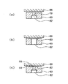
実施例5は、本発明の実施形態の1つである。図8は、隙間量調整型気体制御駆動部の微小移動と、それよりは移動量の大きく取れるラム型気体制御駆動部の粗動移動とを組み合わせた粗微動連動型気体制御駆動部160の構成を示す図である。基本的な構成は、図7の球面可動体連動ラム型気体制御駆動部150において、第1可動体を駆動する気体と独立に、第2可動体を駆動する気体を隙間量調整用気体供給口CP2から供給するようにしたものである。したがって、第1可動体162には制御気体供給口CP1から気体室116を経てその駆動用気体圧が供給され、球面可動体である第2可動体166の先端部122と気体受面124との間の隙間には、これと独立に連通気体供給路168を用いて隙間量調整用気体供給口CP2から隙間量調整用気体圧が供給される。球面座164およびこれに対応する曲面については、図5、図7で説明した内容と同様である。図7と同様の要素には同一の符号を付し、詳細な説明を省略する。
Example 5 is one embodiment of the present invention. FIG. 8 shows the configuration of the coarse / fine movement interlocking gas
なお、第2可動体166の先端部の気体供給路168には、図2で説明したと同様な絞り部120が設けられる。また、図示されていないが、気体供給路168が第1可動体162の球面座164と第2可動体166との間の隙間に開口する部分に絞り機構を設ける場合は、CP2からの気体を利用し、さらに、第2可動体166の先端部122からも流したいので、図4で説明した自成絞り78又は表面絞り80のいずれかを用いるのがよい。
Note that the
このような構成の粗微動連動型気体制御駆動部160においては、制御部50の制御の下に制御気体圧供給口CP1から気体室116に制御気体圧が供給され、その気体圧に応じて第1可動体162を軸方向に移動させる駆動力が与えられる。そして、それと独立に、隙間量調整用気体供給口CP2から連通気体供給路168に導入された気体は、好ましくは図示されていない絞り機構を介して第1可動体162と第2可動体166との間の球面状隙間に流れ、また、第2可動体166の中の連通気体供給路168を通り絞り部120を介して第2可動体166の先端部122から矩形軸32の気体受面124に向かって流れ出す。
In the coarse / fine motion interlocking gas
このとき、図5で説明したように、他の気体制御駆動部より受ける押付力Fと釣り合ったところで、第1可動体162と第2可動体166との間の球面隙間、及び球面可動体である第2可動体166と矩形軸32との間の隙間量がそれぞれ定まる。したがって、制御部50は、他の気体制御駆動部より受ける押付力Fを計算に入れ、矩形軸32の必要変位量に対応した隙間量になるように、隙間量調整用気体圧を設定することになる。
At this time, as described with reference to FIG. 5 , the spherical clearance between the first
したがって、第2可動体166の先端部122は、第1可動体162の制御気体圧による移動量の比較的大きい粗動と、第2可動体166の隙間量調整用気体圧による精密に制御された微小移動量との和に相当する移動を行うことができる。そして、球面座164の作用によって矩形軸32の傾きに滑らかに追従しつつ、矩形軸32に接触することなく、駆動力を矩形軸32に伝達することができる。
Therefore, the
実施例6は、本発明の実施形態の1つである。図9は、隙間量調整型気体制御駆動部に、2つの連動する可動体を用いて、微小移動量の範囲を大きくする連動隙間量調整型気体制御駆動部170の構成を示す図である。基本的な構成は図5の隙間量調整型気体制御駆動部130と同じで、可動体が第1可動体172と、第2可動体176と分かれる。球面座174は第1可動体172の先端に設けられ、第2可動体176にはそれに対応する曲面が設けられる。これらについては、図5等で説明した内容と同様である。そして、隙間量調整用気体供給口CP2からの気体供給路も第1可動体172と第2可動体176とを連通する連通気体供給路178となる。図5と同様の要素には同一の符号を付し、詳細な説明を省略する。
Example 6 is one embodiment of the present invention. FIG. 9 is a diagram illustrating a configuration of an interlocking gap amount adjusting type gas
なお、第2可動体176の先端部の気体供給路178には、図2で説明したと同様な絞り部120が設けられる。また、図示されていないが、気体供給路178が本体部12と第1可動体172との間の隙間に開口する部分、及び第1可動体172の球面座174と第2可動体176との間の隙間に開口する部分にそれぞれ絞り機構を設ける場合は、CP2からの気体をそれぞれ利用し、さらに、第2可動体176の先端部122からも流したいので、図4で説明した自成絞り78又は表面絞り80のいずれかを用いるのがよい。
Note that the
このような構成の連動隙間量調整型気体制御駆動部170においては、制御部50の制御の下に隙間量調整用気体圧供給口CP2から隙間量調整用気体圧が供給され、その気体は、連通気体供給路178を通り、好ましくは図示されていない絞り機構を介し本体部12と第1可動体172との間の隙間に流れ、第1可動体172の中を通る連通気体供給路178から、好ましくは図示されていない絞り機構を介し第1可動体172と第2可動体176との間の球面状隙間に流れ、さらに第2可動体176の中を通る連通気体供給路178から絞り部120を介して第2可動体176の先端部122から矩形軸32の気体受面124に向かって流れ出す。
In the interlocking gap amount adjusting type gas
このとき、図5で説明したように、他の気体制御駆動部より受ける押付力Fと釣り合ったところで、本体部12と第1可動体172との間の隙間、第1可動体172と第2可動体176との間の球面隙間、及び球面可動体である第2可動体176と矩形軸32との間の隙間量がそれぞれ定まる。したがって、制御部50は、他の気体制御駆動部より受ける押付力Fを計算に入れ、矩形軸32の必要変位量に対応した隙間量になるように、隙間量調整用気体圧を設定することになる。
At this time, as described with reference to FIG. 5 , when the pressing force F received from another gas control drive unit is balanced, the gap between the
したがって、第2可動体176の先端部122は、第1可動体172の微小移動量と第2可動体176の微小移動量との和に相当する拡大された範囲の微小移動を行うことができる。そして、球面座174の作用によって矩形軸32の傾きに滑らかに追従しつつ、矩形軸32に接触することなく、駆動力を矩形軸32に伝達することができる。
Therefore, the
つぎに、複数の気体制御駆動部100の配置について説明する。実施例7は、本発明の実施形態の1つである。気体制御駆動部100としては、実施例1から実施例6で説明した気体制御部の中のいずれも用いることができる。複数の気体制御駆動部100と矩形軸32との相対的な配置は、気体制御回転移動装置10の回転方向、回転角度の範囲、移動量の範囲等に合わせ、様々な態様をとることが可能である。図10に、そのいくつかの例を示す。これらの図において、本体部12とテーブル30の矩形軸32とに対する配置関係を示すため、複数の気体制御駆動部はそれぞれ斜線で示してある。図10(a)に示す配置関係は、図1で説明したものと同じである。これら4つの気体制御駆動部は、矩形軸32の各辺に対応して1つずつ設けられ、向かい合う気体制御駆動部の駆動軸方向は、互いにオフセットを有している。このオフセットは、矩形軸32の各辺に対する各気体制御駆動部の駆動軸の位置が、図10(a)の紙面上で、矩形軸32の各辺の中心から反時計方向にずらした位置となっている。したがって、図10(a)の配置を用いることで、各気体制御駆動部を駆動させ、矩形軸32の各辺を押したとき、矩形軸32を反時計方向(CCW:Counter ClockWise)に回転させることができる。その意味で、気体制御駆動部にCCWの符号を付した。この場合図1に関連して説明したように、図示されていない適当な反力機構を用いることで、最小の数の気体制御駆動部を用い図10(a)の配置構成で、X−Y−θ移動を行うことができる。また、図1の説明で述べたように、この構成で、回転に加えて、XY平面内で矩形軸32の移動を行うことも可能である。
Next, the arrangement of the plurality of gas
図10(b)は、矩形軸32を、紙面上で時計方向(CW:ClockWise)にも回転できるように、複数の気体制御駆動部を配置する例を示す図である。CCWの符号を付した気体制御駆動部を駆動することで、矩形軸32を反時計方向に回転でき、CWの符号を付した気体制御駆動部を駆動することで、矩形軸32を時計方向に回転できる。またこれらの組み合わせで、回転に加えて、XY平面内で矩形軸32の移動を行うことも可能である。
FIG. 10B is a diagram illustrating an example in which a plurality of gas control driving units are arranged so that the
この場合、上記のように、CWまたはCCWのみを駆動するようにしてもよく、各気体制御駆動部に標準気体圧を常に供給することで矩形軸32の位置を中立に維持し、移動又は回転のときに、各気体制御駆動部に標準気体圧からのプラス差圧又はマイナス差圧をさらに与えることとしてもよい。例えば、図10(b)において、CCWに対応する各気体制御駆動部に(標準気体圧+ΔP)を供給し、CWに対応する各気体制御駆動部に(標準気体圧−ΔP)を供給することで、矩形軸32を、反時計方向に回転できる。このときは、標準気体圧を中心に、向かい合う各気体制御駆動部がお互いに反力を及ぼし合っているので、図10(a)で必要である反力機構を特に必要としない。なお、反力機構を特に必要としないことは、以下の図10(c),(d),(e)の場合も同じである。
In this case, as described above, only the CW or CCW may be driven, and the standard gas pressure is always supplied to each gas control drive unit to maintain the position of the
図10(c)は、矩形軸32の辺の中央に駆動軸方向を有する気体制御駆動部を配置する例を示すもので、この種類の気体制御駆動部には中立(Nutral)の意味でNの符号を付してある。Nの符号を付した気体制御駆動部は、それに向かい合うCW,CCWの符号を付した気体制御駆動部に対し、紙面上での時計方向、反時計方向の駆動の効果的な支点として用いることができる。また、XY平面内で矩形軸32の移動を行うときも便利である。
FIG. 10 (c), shows an example of placing a gas control driver having a drive shaft direction in the center of the sides of the
図10(d),(e)は、CW,CCW,Nの各種類の気体制御駆動部を組み合わせ配置する他の例を示す図である。このように、気体制御回転移動装置10の仕様に応じ、複数の気体制御駆動部について様々な態様をとることが可能である。
FIGS. 10D and 10E are diagrams showing another example in which gas control drive units of CW, CCW, and N are combined and arranged. As described above, various modes can be adopted for the plurality of gas control drive units in accordance with the specifications of the gas control
実施例8は、本発明の実施形態の1つである。図11は、粗微動連動型気体制御駆動部160を用いた気体制御回転移動装置180の断面図である。粗微動連動型気体制御駆動部160の内部構成は図8に関連して説明した内容であるので、各要素の符号を省略した。また、図1と同様の要素については同一の符号を付し詳細な説明を省略する。
Example 8 is one embodiment of the present invention. FIG. 11 is a cross-sectional view of a gas control
図11において、本体部12の上下面には、テーブル30のステージ34の裏面に向かって気体を噴出させ、気体軸受作用でステージ34を本体部12の上下面から浮上させるための気体軸受用気体供給口SBと、その排気口EXとが設けられる。粗微動連動型気体制御駆動部160と矩形軸32との間も気体により駆動力が伝達されるので、これとあいまって、テーブル30は、全体として本体部12と接触しない。
In FIG. 11, gas for gas bearings is formed on the upper and lower surfaces of the
この気体制御回転移動装置180においては、制御部50から、各粗微動連動型気体制御駆動部160の、制御気体供給口CP1と、隙間制御用気体供給口CP2とに、それぞれ所定の気体圧の気体が供給される。制御気体供給口CP1に供給される気体圧は、粗動駆動用の気体圧で、要求される駆動力を第1可動体の気体受面積で徐した値を基準に設定される。隙間制御用気体供給口CP2に供給される気体圧は、微小駆動用の気体圧で、他の気体制御駆動部より受ける押付力F1又はF2を計算に入れ、矩形軸32の必要微小変位量に対応した隙間量になるように設定される。
In the gas control
例えば、粗微動連動型気体制御駆動部160の先端部において、矩形軸を元の位置から1mm+2μm移動させることが要求されるとすると、1mmの移動駆動を制御気体供給口CP1からの気体圧によって行わせ、2μmの移動駆動を隙間制御用気体供給口CP2からの気体圧によって行わせることができる。上記の例で、粗動の1mmの移動については、μmレベルの制御が困難なことがあり、1mm+2μmの移動に対応する角度変化を精密に制御するためには、センサ40+測定部42のデータを制御部50にフィードバックすることが好ましい。また、回転に加えて、XY平面内でテーブルを粗微小移動することもできる。
For example, if it is required to move the rectangular axis by 1 mm + 2 μm from the original position at the tip of the coarse / fine movement interlocking gas
実施例9は、本発明の実施形態ではないが、本発明の参考となる参考例の1つである。 図12は、隙間量調整型気体制御駆動部130を用いた気体制御回転移動装置190の断面図である。隙間量調整型気体制御駆動部130は図5に関連して説明した内容であるので、各要素の符号を省略した。また、図11と同様の要素については同一の符号を付し詳細な説明を省略する。
Example 9 is not an embodiment of the present invention, but is one of reference examples for reference of the present invention. FIG. 12 is a cross-sectional view of the gas control
この気体制御回転移動装置190においては、制御部50から、各隙間量調整型気体制御駆動部130の隙間制御用気体供給口CP2に、微小駆動用の隙間量調整用気体圧が供給される。この隙間量調整用気体圧は、他の気体制御駆動部より受ける押付力F1又はF2を計算に入れ、矩形軸32の必要微小変位量に対応した隙間量になるように設定される。
In the gas control
例えば、隙間量調整型気体制御駆動部130の先端部において、矩形軸を元の位置から2μm移動させることが要求されるとすると、隙間量調整型気体制御駆動部130の先端部と、これに対応する矩形軸32の辺との間の隙間を、押付力F1又はF2に抗して、2μm増加させるのに必要な気体圧の気体が制御部50によって生成制御され、隙間制御用気体供給口CP2に供給される。このようにして、2μ移動に対応する微小角度の回転をテーブル30に行わせることができる。また、回転に加えて、XY平面内でテーブルを微小移動することもできる。隙間量制御は、特に必要がなければ、オープンループの制御で十分なので、センサ40+測定部42のデータを制御部50にフィードバックしなくてもよい。
For example, if it is required to move the rectangular axis by 2 μm from the original position at the tip of the gap amount adjustment type gas
図11、図12は、代表的な構成の気体制御回転移動装置について説明したが、気体制御駆動部の種類をこれらに用いたものと異なる種類のものに代えて構成することもできる。また、上記では、テーブルは矩形軸を有するものとしたが、辺の数は4に限られず、多角形軸であってもよく、また円筒軸の円周に沿って適当な間隔で複数の気体受面を設けることとしてもよい。 11 and 12 have described the gas control rotary movement device having a typical configuration, but the type of the gas control drive unit may be replaced with a different type from those used for these. In the above description, the table has a rectangular axis. However, the number of sides is not limited to four, and may be a polygonal axis. A plurality of gases may be arranged at appropriate intervals along the circumference of the cylindrical axis. A receiving surface may be provided.
10,180,190 気体制御回転移動装置、12 本体部、14 支持穴、30 テーブル、32 矩形軸、34 ステージ、40 センサ、42 測定部、50 制御部、60,114 可動体、62 気体供給路、64 ポケット開口、66 対象物、68,124 気体受面、69 気体受壁、72 円環板、74 円板、76 多孔質材料、78 自成絞り、80 表面絞り、82 ポケット絞り、100 気体制御駆動部、110 ラム型気体制御駆動部、112 案内、116 気体室、118,136 気体供給路、120 絞り部、122 先端部、130 隙間量調整型気体制御駆動部、132,154,164,174 球面座、134 球面可動体、140 連動ラム型気体制御駆動部、144,152,162,172 第1可動体、146,156,166,176 第2可動体、148,158,168,178 連通気体供給路、150 球面可動体連動ラム型気体制御駆動部、160 粗微動連動型気体制御駆動部、170 連動隙間量調整型気体制御駆動部。 10, 180, 190 Gas control rotary movement device, 12 body part, 14 support hole, 30 table, 32 rectangular shaft, 34 stage, 40 sensor, 42 measurement part, 50 control part, 60, 114 movable body, 62 gas supply path , 64 pocket opening, 66 object, 68,124 gas receiving surface, 69 gas receiving wall, 72 circular plate, 74 disc, 76 porous material, 78 self-contained diaphragm, 80 surface diaphragm, 82 pocket diaphragm, 100 gas Control drive unit, 110 Ram type gas control drive unit, 112 Guide, 116 Gas chamber, 118, 136 Gas supply path, 120 Throttle unit, 122 Tip, 130 Gap amount adjustment type gas control drive unit, 132, 154, 164 174 spherical seat, 134 spherical movable body, 140 interlocking ram type gas control drive unit, 144, 152, 162, 172 first movable body, 46, 156, 166, 176 Second movable body, 148, 158, 168, 178 Continuous ventilation body supply path, 150 Spherical movable body interlocking ram type gas control driving part, 160 Coarse / fine motion interlocking type gas control driving part, 170 Interlocking gap amount Adjustable gas control drive.
Claims (5)
多角形軸を有し、前記本体部に対し前記多角形軸の軸方向に垂直な平面内で移動可能なテーブルと、
前記テーブルの前記多角形軸の各辺に対応してそれぞれ設けられる複数の駆動部であって、各駆動部は、
前記多角形軸に向かって連動して移動する可動体として、底面が前記本体部に向かい合い先端に球面座を有する第1可動体と、先端面が前記多角形軸の対応する前記辺に向かい合い、底面が前記第1可動体の前記球面座に対応する曲面を有する第2可動体とを含み、前記多角形軸の対応する前記辺を気体受面として、前記第2可動体の前記先端面と前記気体受面との間に供給される気体を介して前記多角形軸を非接触で駆動する複数の気体制御駆動部と、
前記各気体制御駆動部の駆動を協働的に制御し、前記テーブルの前記平面内移動または前記多角形軸の前記軸周りの任意角度の回転の少なくともいずれか1の制御を含む制御部と、
を備え、
前記各気体制御駆動部は、
前記本体部と前記第1可動体の底面との間の隙間、前記第1可動体の前記球面座と前記第2可動体の底面との間の隙間、及び前記第2可動体の前記先端面と前記気体受面との間の隙間にそれぞれ気体を供給する気体供給路を含み、
前記制御部は、前記気体供給路に供給する気体圧を隙間量調整用気体圧として制御し、他の前記気体制御駆動部より受ける押付力と釣り合わせつつ、前記本体部と前記第1可動体の底面との間の隙間量、前記第1可動体の前記球面座と前記第2可動体の底面との間の隙間量、及び前記第2可動体の前記先端面と前記気体受面との間の隙間量とを調整して前記テーブルを前記平面内の微小移動または前記軸周りの微小回転をさせることを特徴とする気体制御回転移動装置。 A main body that is a base;
A table having a polygonal axis and movable in a plane perpendicular to the axial direction of the polygonal axis with respect to the main body ;
A plurality of driving portions provided corresponding to the respective sides of the polygon axis of the table, each of the drive unit,
Examples movable body that moves in conjunction toward the polygonal shaft, confronts the side and first movable body, the distal end surface corresponding the polygonal shaft with a spherical seat on the tip face each bottom to the main body portion, bottom and a second movable member having a curved surface corresponding to the spherical seat of the first movable body, as said corresponding side of the gas receiving surface of the polygonal shaft, and the distal end surface of the second movable member a plurality of gas control driver you drive the polygonal shaft in a non-contact manner via a gas supplied between said gas receiving surface,
The controls to drive the cooperative of each gas control driver, the or plane movement of the table and a control unit including at least one first control rotation of any angle around the axis of the polygonal shaft ,
With
Each gas control driving unit,
Clearance between the bottom surface of the first movable member and the body portion, the distal end surface of the gap, and the second movable member between said spherical seat and the bottom surface of the second movable member of the first movable body and includes a gas supply passage for supplying the respective gas into the gap between the gas-receiving surface,
Wherein the control unit, the gas pressure supplied to the gas supply passage to control a gap amount adjustment pneumatic, while balanced with the pressing force received from the other of the gas control driver, the first movable member and the body portion the amount of clearance between the bottom surface, the amount of clearance between the spherical seat and the bottom surface of the second movable member of the first movable member, and the distal end surface of the second movable member and with said gas receiving surface gas control rotational movement apparatus to said table by adjusting the gap amount or small movement of the plane, characterized in that for the fine rotation about said axis between.
多角形軸を有し、前記本体部に対し前記多角形軸の軸方向に垂直な平面内で移動可能なテーブルと、
前記テーブルの前記多角形軸の各辺に対応してそれぞれ設けられる複数の駆動部であって、各駆動部は、
前記本体部に設けられる案内部と、
前記案内部の軸方向に沿って案内され前記多角形軸に向かって連動して移動する複数の可動体として、前記案内部の底部側から粗動駆動用の制御気体圧を受ける底面と先端に球面座を有する第1可動体と、前記多角形軸の各辺を気体受面として、前記気体受面と前記第1可動体の間に配置され、先端が前記先端面で、底面が前記第1可動体の前記球面座に対応する曲面を有する第2可動体とを含み、前記先端面と前記気体受面との間に供給される気体を介して前記多角形軸を非接触で駆動する複数の気体制御駆動部と、
前記各気体制御駆動部の駆動を協働的に制御し、前記テーブルの前記平面内移動または前記多角形軸の前記軸周りの任意角度の回転の少なくともいずれか1の制御を含む制御部と、
を備え、
前記各気体制御駆動部は、
前記第1可動体を粗動駆動する気体として、前記第1可動体の底面に向けて前記制御気体圧を有する気体を供給する制御気体圧供給口と、
前記第1可動体に対し前記第2可動体を微小移動駆動する気体として、前記制御気体圧とは独立の気体圧の隙間量調整用気体圧を有する気体を、前記第1可動体の前記球面座と前記第2可動体の底面との間の隙間、及び前記第2可動体の前記先端面と前記気体受面との間の隙間にそれぞれ供給する連通気体供給路と、を含み、
前記制御部は、前記第1可動体の前記粗動駆動とは独立に、前記連通気体供給路に供給する前記隙間量調整用気体圧を制御し、他の前記気体制御駆動部より受ける押付力と釣り合わせつつ、前記第1可動体の前記球面座と前記第2可動体の底面との間の隙間量、及び前記第2可動体の前記先端面と前記気体受面との間の隙間量とを調整して前記テーブルを前記平面内の微小移動または前記軸周りの微小回転をさせることを特徴とする気体制御回転移動装置。 A main body that is a base;
A table having a polygonal axis and movable in a plane perpendicular to the axial direction of the polygonal axis with respect to the main body;
A plurality of driving units respectively provided corresponding to each side of the polygon axis of the table, each driving unit,
A guide part provided in the main body part;
As a plurality of movable bodies that are guided along the axial direction of the guide portion and move in conjunction with the polygonal axis, a bottom surface and a front end that receive a control gas pressure for coarse driving from the bottom side of the guide portion. a first movable member having a spherical seat, as a gas receiving surface of each side of the polygonal shaft, the disposed between the gas receiving face and the first movable member, the tip is at the front end surface, the bottom surface first and a second movable member having a curved surface corresponding to the spherical seat of the first movable body, for driving said polygonal shaft via a gas supplied between the gas receiving surface and said tip surface in a non-contact A plurality of gas control drive units;
A control unit that cooperatively controls driving of each of the gas control driving units, and includes at least one control of the in-plane movement of the table or rotation of the polygonal axis around the axis;
With
Each gas control drive unit is
A control gas pressure supply port for supplying a gas having the control gas pressure toward the bottom surface of the first movable body as a gas for coarsely driving the first movable body;
Said second movable member against the first movable member as a gas to drive fine movement, the gas having a gap amount adjustment pneumatic independent gas pressure from said control gas pressure, the spherical surface of the first movable body clearance between the bottom of the the seat second movable member, and includes a communicating vent member supply passage gap Niso respectively supplied between the distal end surface and the gas receiving surface of the second movable member ,
Wherein, independently of the coarse drive of the first movable member, the communicating vent body the controls gap amount adjustment gas pressure supplied to the supply passage, the pressing force received from the other of the gas control driver while mated with the gap amount between the gap amount, and the said front end surface of the second movable member and said gas receiving surface between said spherical seat and the bottom surface of the second movable member of the first movable body preparative gas control rotational movement and wherein the said table and adjust it to a small rotation around the minute movement or the axis of the plane of.
前記テーブルの回転移動を検出し前記制御部に出力するセンサを備えることを特徴とする気体制御回転移動装置。 In the gas control rotation movement device according to claim 1 or 2 ,
Gas control rotational movement device, characterized in that it comprises a sensor for outputting to the control unit detects the rotation movement of the table.
前記移動対象物に向かい合って設けられる可動部であって、前記移動対象物に向かって連動して移動する複数の可動体として、底面が前記本体部に向かい合い先端に球面座を有する第1可動体と、先端面が前記移動対象物に向かい合い、底面が前記第1可動体の前記球面座に対応する曲面を有する第2可動体とを含み、前記移動対象物の面を気体受面として、前記第2可動体の前記先端面と前記気体受面との間に供給される気体を介して前記移動対象物を非接触で駆動する可動部と、
前記本体部と前記第1可動体の底面との間の隙間、前記第1可動体の前記球面座と前記第2可動体の底面との間の隙間、及び前記第2可動体の前記先端面と前記気体受面との間の隙間にそれぞれ気体を供給する気体供給路と、
前記気体受面に向かって前記各隙間の気体を圧縮しつつ前記移動対象物と前記可動部とを押し付ける押付力発生部と、
前記気体供給路に供給する気体圧を隙間量調整用気体圧として制御し、前記押付力と釣り合わせつつ、前記本体部と前記第1可動体の底面との間の隙間量、前記第1可動体の前記球面座と前記第2可動体の底面との間の隙間量、及び前記第2可動体の前記先端面と前記気体受面との間の隙間量とを調整して前記移動対象物を微小移動させる制御部と、
を備えることを特徴とする気体制御アクチュエータ。 A main body that is a base for a moving object;
A movable part provided to face the moving object, wherein the first movable body has a bottom surface facing the body part and a spherical seat at the tip as a plurality of movable bodies that move in conjunction with the moving object. And a second movable body having a tip surface facing the moving object and a bottom surface having a curved surface corresponding to the spherical seat of the first movable body, the surface of the moving object as a gas receiving surface, A movable part that drives the moving object in a non-contact manner through a gas supplied between the tip surface of the second movable body and the gas receiving surface ;
Clearance between the bottom surface of the first movable member and the body portion, the distal end surface of the gap, and the second movable member between said spherical seat and the bottom surface of the second movable member of the first movable body a gas supply channel for supplying gas respectively in the gap between said gas receiving surface,
A pressing force generating unit for pressing said toward said gas receiving surface with the gas the moving object while compressing the each gap between the movable portion,
The gas pressure supplied to the gas supply passage to control the gap size adjusting gas pressure, while balanced with the pressing force, amount of clearance between the bottom surface of the first movable body and the main body portion, said first movable amount of clearance between the spherical seat and the bottom surface of the second movable member body, and the gap amount and the moving object to adjust the between the front end surface and the gas receiving surface of the second movable member A control unit for minute movement,
A gas control actuator comprising:
前記本体部に設けられる案内部と、
前記案内部の軸方向に沿って案内され前記移動対象物に向かって連動して移動する可動部であって、粗動駆動用の制御気体圧を受ける底面と先端に球面座を有する第1可動体と、前記移動対象物の面を気体受面として、前記気体受面と前記第1可動体との間に配置され、先端面が前記気体受面に向かい合い、底面が前記第1可動体の前記球面座に対応する曲面を有する第2可動体とを含み、前記先端面と前記気体受面との間に供給される気体を介して前記移動対象物を非接触で駆動する可動部と、
前記案内部の底面に設けられ、前記第1可動体を粗動駆動する気体として前記制御気体圧を有する気体を前記第1可動体の底面に向けて供給する制御気体圧供給口と、
前記第1可動体に対し前記第2可動体を微小移動駆動する気体として、前記制御気体圧とは独立の気体圧の隙間量調整用気体圧を有する気体を、前記第1可動体の前記球面座と前記第2可動体の底面との間の隙間、及び前記第2可動体の前記先端面と前記気体受面との間の隙間に、それぞれ供給する連通気体供給路と、
前記気体受面に向かって前記各隙間の気体を圧縮しつつ前記移動対象物と前記可動部とを押し付ける押付力発生部と、
前記第1可動体の前記粗動駆動とは独立に、前記連通気体供給路に供給する前記隙間量調整用気体圧を制御し、前記押付力と釣り合わせつつ、前記第1可動体の前記球面座と前記第2可動体の底面との間の隙間量、及び前記第2可動体の前記先端面と前記気体受面との間の隙間量とを調整して前記移動対象物を微小移動させる制御部と、
を備えることを特徴とする気体制御アクチュエータ。 A main body that is a base for a moving object;
A guide part provided in the main body part;
A movable portion that is guided along the axial direction of the guide portion and moves in conjunction with the moving object, the first movable portion having a bottom surface that receives a control gas pressure for coarse driving and a spherical seat at the tip. and body, as a gas receiving surface to a surface of the moving object, wherein disposed between the gas receiving surface and said first movable member, the tip end surface confronts the gas receiving surface, bottom surface of the first movable body A second movable body having a curved surface corresponding to the spherical seat, and a movable portion that drives the moving object in a non-contact manner through a gas supplied between the tip surface and the gas receiving surface;
A control gas pressure supply port that is provided on the bottom surface of the guide portion and supplies gas having the control gas pressure toward the bottom surface of the first movable body as a gas for coarsely driving the first movable body;
Said second movable member against the first movable member as a gas to drive fine movement, the gas having a gap amount adjustment pneumatic independent gas pressure from said control gas pressure, the spherical surface of the first movable body clearance between the bottom of the the seat second movable member, and the gap between the front end surface and the gas receiving surface of the second movable member, the communicating vent body supply path for supplying respectively,
A pressing force generating unit for pressing said toward said gas receiving surface with the gas the moving object while compressing the each gap between the movable portion,
Independently of the coarse drive of the first movable member, said controlling the communication vent body the gap amount adjusting gas pressure supplied to the supply path, while balanced with the pressing force, the spherical surface of the first movable body amount of clearance between the bottom of the the seat second movable body, and is slightly moved to the moving object by adjusting the amount of clearance between the tip surface and the gas receiving surface of the second movable member A control unit;
A gas control actuator comprising:
Priority Applications (1)
| Application Number | Priority Date | Filing Date | Title |
|---|---|---|---|
| JP2005020947A JP4740605B2 (en) | 2005-01-28 | 2005-01-28 | Gas control rotary movement device and gas control actuator |
Applications Claiming Priority (1)
| Application Number | Priority Date | Filing Date | Title |
|---|---|---|---|
| JP2005020947A JP4740605B2 (en) | 2005-01-28 | 2005-01-28 | Gas control rotary movement device and gas control actuator |
Publications (3)
| Publication Number | Publication Date |
|---|---|
| JP2006210659A JP2006210659A (en) | 2006-08-10 |
| JP2006210659A5 JP2006210659A5 (en) | 2008-03-13 |
| JP4740605B2 true JP4740605B2 (en) | 2011-08-03 |
Family
ID=36967156
Family Applications (1)
| Application Number | Title | Priority Date | Filing Date |
|---|---|---|---|
| JP2005020947A Active JP4740605B2 (en) | 2005-01-28 | 2005-01-28 | Gas control rotary movement device and gas control actuator |
Country Status (1)
| Country | Link |
|---|---|
| JP (1) | JP4740605B2 (en) |
Families Citing this family (2)
| Publication number | Priority date | Publication date | Assignee | Title |
|---|---|---|---|---|
| NL2003846A (en) * | 2008-12-19 | 2010-06-22 | Asml Netherlands Bv | Lithographic apparatus with gas pressure means for controlling a planar position of a patterning device contactless. |
| EP2221668B1 (en) | 2009-02-24 | 2021-04-14 | ASML Netherlands B.V. | Lithographic apparatus and positioning assembly |
Family Cites Families (12)
| Publication number | Priority date | Publication date | Assignee | Title |
|---|---|---|---|---|
| JPS5388440A (en) * | 1977-01-14 | 1978-08-03 | Hitachi Ltd | Static pressure bearing guide |
| JPS53121569A (en) * | 1977-03-31 | 1978-10-24 | Toshiba Corp | Vapor growth method |
| JPS5687318A (en) * | 1979-12-18 | 1981-07-15 | Toshiba Corp | Finely movable table |
| JPS59129636A (en) * | 1983-01-10 | 1984-07-26 | Hitachi Ltd | Controller of stage with freedom of six |
| JPS6022239A (en) * | 1983-07-18 | 1985-02-04 | Fujitsu Ltd | Voice data editing system |
| JPH061956B2 (en) * | 1984-08-10 | 1994-01-05 | 九州日立マクセル株式会社 | Charging circuit |
| JPS62147433A (en) * | 1985-12-20 | 1987-07-01 | Matsushita Electric Ind Co Ltd | Relieving method for line defect of liquid crystal display panel |
| JPS62156425A (en) * | 1985-12-28 | 1987-07-11 | Fudo Constr Co Ltd | Driving work of shield plate |
| JPS63245347A (en) * | 1987-03-31 | 1988-10-12 | Sumitomo Heavy Ind Ltd | Minute drive structure |
| JPH029550A (en) * | 1988-12-21 | 1990-01-12 | Hitachi Ltd | Driving device for six-degree-freedom fine moving stage |
| JPH09317767A (en) * | 1996-05-28 | 1997-12-09 | Nippon Seiko Kk | Positioning device |
| JPH10148204A (en) * | 1996-11-18 | 1998-06-02 | Ckd Corp | Actuator |
-
2005
- 2005-01-28 JP JP2005020947A patent/JP4740605B2/en active Active
Also Published As
| Publication number | Publication date |
|---|---|
| JP2006210659A (en) | 2006-08-10 |
Similar Documents
| Publication | Publication Date | Title |
|---|---|---|
| JP2010096311A (en) | Hydrostatic bearing pad, linear guide apparatus, and rotation guide apparatus | |
| JPH07111238A (en) | Self-weight support device | |
| JPS63285303A (en) | Multiple port valve | |
| JP4740605B2 (en) | Gas control rotary movement device and gas control actuator | |
| JP4106392B2 (en) | Gas pressure control actuator, gas bearing mechanism for gas pressure control actuator, and minute displacement output device using gas pressure control actuator | |
| US6881918B2 (en) | Electric discharge machining apparatus | |
| JP5084580B2 (en) | Mobile device | |
| JP2017133593A (en) | Fluid pressure actuator | |
| JP2017009068A (en) | Fluid pressure actuator | |
| JP2009068555A (en) | Fluid bearing structure and assembling method of fluid bearing | |
| JP2006153140A (en) | Minute flow rate controller | |
| JP4171666B2 (en) | Actuator capable of linear and rotary motion | |
| JP4607658B2 (en) | Gas control actuator | |
| US9151369B2 (en) | Aerostatic air bearing, assembling method thereof, and aerostatic lead screw actuator using the same | |
| JP4845114B2 (en) | Spindle device | |
| JP2004011686A (en) | Air bearing | |
| JP5994298B2 (en) | Moving table equipment | |
| JP4807680B2 (en) | Hydrostatic joint | |
| JP4529127B2 (en) | Support device and processing machine | |
| JP5239397B2 (en) | Balance cylinder device | |
| JP2005351312A (en) | Moving mechanism | |
| JP2009063046A (en) | Gas pressure control actuator | |
| JP7158815B2 (en) | rotary table device | |
| JP2019202358A (en) | Grinding device | |
| JP2006057719A (en) | Nozzle flapper valve |
Legal Events
| Date | Code | Title | Description |
|---|---|---|---|
| A521 | Request for written amendment filed |
Free format text: JAPANESE INTERMEDIATE CODE: A523 Effective date: 20080125 |
|
| A621 | Written request for application examination |
Free format text: JAPANESE INTERMEDIATE CODE: A621 Effective date: 20080125 |
|
| A977 | Report on retrieval |
Free format text: JAPANESE INTERMEDIATE CODE: A971007 Effective date: 20100331 |
|
| A131 | Notification of reasons for refusal |
Free format text: JAPANESE INTERMEDIATE CODE: A131 Effective date: 20100518 |
|
| A521 | Request for written amendment filed |
Free format text: JAPANESE INTERMEDIATE CODE: A523 Effective date: 20100720 |
|
| TRDD | Decision of grant or rejection written | ||
| A01 | Written decision to grant a patent or to grant a registration (utility model) |
Free format text: JAPANESE INTERMEDIATE CODE: A01 Effective date: 20110419 |
|
| A01 | Written decision to grant a patent or to grant a registration (utility model) |
Free format text: JAPANESE INTERMEDIATE CODE: A01 |
|
| A61 | First payment of annual fees (during grant procedure) |
Free format text: JAPANESE INTERMEDIATE CODE: A61 Effective date: 20110502 |
|
| R150 | Certificate of patent or registration of utility model |
Ref document number: 4740605 Country of ref document: JP Free format text: JAPANESE INTERMEDIATE CODE: R150 Free format text: JAPANESE INTERMEDIATE CODE: R150 |
|
| FPAY | Renewal fee payment (event date is renewal date of database) |
Free format text: PAYMENT UNTIL: 20140513 Year of fee payment: 3 |
|
| S531 | Written request for registration of change of domicile |
Free format text: JAPANESE INTERMEDIATE CODE: R313531 |
|
| R350 | Written notification of registration of transfer |
Free format text: JAPANESE INTERMEDIATE CODE: R350 |
|
| R250 | Receipt of annual fees |
Free format text: JAPANESE INTERMEDIATE CODE: R250 |
|
| R250 | Receipt of annual fees |
Free format text: JAPANESE INTERMEDIATE CODE: R250 |
|
| R250 | Receipt of annual fees |
Free format text: JAPANESE INTERMEDIATE CODE: R250 |
|
| R250 | Receipt of annual fees |
Free format text: JAPANESE INTERMEDIATE CODE: R250 |
|
| R250 | Receipt of annual fees |
Free format text: JAPANESE INTERMEDIATE CODE: R250 |
|
| R250 | Receipt of annual fees |
Free format text: JAPANESE INTERMEDIATE CODE: R250 |
|
| R250 | Receipt of annual fees |
Free format text: JAPANESE INTERMEDIATE CODE: R250 |
|
| R250 | Receipt of annual fees |
Free format text: JAPANESE INTERMEDIATE CODE: R250 |