JP4740230B2 - Flowmeter for use with high pressure process fluids - Google Patents
Flowmeter for use with high pressure process fluids Download PDFInfo
- Publication number
- JP4740230B2 JP4740230B2 JP2007508368A JP2007508368A JP4740230B2 JP 4740230 B2 JP4740230 B2 JP 4740230B2 JP 2007508368 A JP2007508368 A JP 2007508368A JP 2007508368 A JP2007508368 A JP 2007508368A JP 4740230 B2 JP4740230 B2 JP 4740230B2
- Authority
- JP
- Japan
- Prior art keywords
- vortex flowmeter
- reduced thickness
- reinforcing rib
- pivot line
- conduit
- Prior art date
- Legal status (The legal status is an assumption and is not a legal conclusion. Google has not performed a legal analysis and makes no representation as to the accuracy of the status listed.)
- Expired - Fee Related
Links
Images


Classifications
-
- G—PHYSICS
- G01—MEASURING; TESTING
- G01F—MEASURING VOLUME, VOLUME FLOW, MASS FLOW OR LIQUID LEVEL; METERING BY VOLUME
- G01F1/00—Measuring the volume flow or mass flow of fluid or fluent solid material wherein the fluid passes through a meter in a continuous flow
- G01F1/05—Measuring the volume flow or mass flow of fluid or fluent solid material wherein the fluid passes through a meter in a continuous flow by using mechanical effects
- G01F1/20—Measuring the volume flow or mass flow of fluid or fluent solid material wherein the fluid passes through a meter in a continuous flow by using mechanical effects by detection of dynamic effects of the flow
- G01F1/32—Measuring the volume flow or mass flow of fluid or fluent solid material wherein the fluid passes through a meter in a continuous flow by using mechanical effects by detection of dynamic effects of the flow using swirl flowmeters
- G01F1/3209—Measuring the volume flow or mass flow of fluid or fluent solid material wherein the fluid passes through a meter in a continuous flow by using mechanical effects by detection of dynamic effects of the flow using swirl flowmeters using Karman vortices
- G01F1/3218—Measuring the volume flow or mass flow of fluid or fluent solid material wherein the fluid passes through a meter in a continuous flow by using mechanical effects by detection of dynamic effects of the flow using swirl flowmeters using Karman vortices bluff body design
-
- G—PHYSICS
- G01—MEASURING; TESTING
- G01F—MEASURING VOLUME, VOLUME FLOW, MASS FLOW OR LIQUID LEVEL; METERING BY VOLUME
- G01F1/00—Measuring the volume flow or mass flow of fluid or fluent solid material wherein the fluid passes through a meter in a continuous flow
- G01F1/05—Measuring the volume flow or mass flow of fluid or fluent solid material wherein the fluid passes through a meter in a continuous flow by using mechanical effects
- G01F1/20—Measuring the volume flow or mass flow of fluid or fluent solid material wherein the fluid passes through a meter in a continuous flow by using mechanical effects by detection of dynamic effects of the flow
- G01F1/32—Measuring the volume flow or mass flow of fluid or fluent solid material wherein the fluid passes through a meter in a continuous flow by using mechanical effects by detection of dynamic effects of the flow using swirl flowmeters
- G01F1/325—Means for detecting quantities used as proxy variables for swirl
- G01F1/3259—Means for detecting quantities used as proxy variables for swirl for detecting fluid pressure oscillations
- G01F1/3266—Means for detecting quantities used as proxy variables for swirl for detecting fluid pressure oscillations by sensing mechanical vibrations
Description
発明の背景
本発明は、流体の流量を計測するための渦流量計に関し、特に、高圧プロセス流体に使用するための流量計に関する。
BACKGROUND OF THE INVENTION The present invention relates to vortex flow meters for measuring fluid flow rates, and more particularly to flow meters for use with high pressure process fluids.
種々の差圧感知型渦流量計が開発されており、これらは、流体流中に配置された緩衝体又は放出バーがその放出バーの両側で交互に渦を発生させ、バーの各側で圧力の変動を生じさせる原理で作動する。個々のバー形状特性に関する渦放出の周波数が流れの中の流速に正比例する。 Various differential pressure sensing vortex flowmeters have been developed that include a buffer or discharge bar disposed in the fluid stream that alternately generates vortices on either side of the discharge bar, and pressure on each side of the bar. It operates on the principle of causing fluctuations. The frequency of vortex shedding for individual bar shape characteristics is directly proportional to the flow velocity in the flow.
渦流量計は従来技術で公知であり、渦流量計の具体例が、引用例として本明細書に取り込む、1990年5月2日にKlevenらに発行された米国特許第4,926,695号、1994年9月6日にBeulkeに発行された米国特許第5,343,762号に見ることができる。 Vortex flowmeters are known in the prior art, and specific examples of vortex flowmeters are disclosed in U.S. Pat. No. 4,926,695 issued to Kleven et al. On May 2, 1990, which is incorporated herein by reference. U.S. Pat. No. 5,343,762, issued September 6, 1994 to Beulke.
通常、流体流量を計測するための渦流量計は、流体を運ぶための内孔を取り囲む壁を有する導管を含む。壁は、その中に形成された厚みを減らした壁領域を有する。厚みを減らした壁領域は、「剛性を落とした領域」又は「撓曲部」と呼ばれることもある。放出バーが内孔中に配置されている。典型的な実施態様では、放出バーは、上流側端部と、下流側端部と、上流側及び下流側両端部を接続する中間部とを含む。中間部は、上流側端部の周囲で流体流によって流体内に形成される乱流又は渦に応答して撓曲して、下流側端部の少なくとも一部の動きを促進する、剛性を落とした領域を含む。このような流量計はさらに、動きを感知し、その関数として出力を提供する、下流側端部に結合された感知手段を含む。一般に、感知手段は、横方向の動きを感知し、内孔から離れる方向に壁領域から延びる支柱に脱着自在に取り付けられ、この支柱が動きを感知手段に伝達する。 A vortex flow meter for measuring fluid flow typically includes a conduit having a wall surrounding an inner bore for carrying fluid. The wall has a reduced wall area formed therein. A wall region with a reduced thickness may be referred to as a “region with reduced rigidity” or a “flexure”. A discharge bar is disposed in the inner bore. In an exemplary embodiment, the discharge bar includes an upstream end, a downstream end, and an intermediate portion connecting the upstream and downstream ends. The intermediate section bends in response to turbulence or vortices formed in the fluid by the fluid flow around the upstream end to reduce the stiffness, facilitating the movement of at least a portion of the downstream end. Including Such a flow meter further includes sensing means coupled to the downstream end that senses motion and provides an output as a function thereof. In general, the sensing means senses lateral movement and is detachably attached to a column extending from the wall region in a direction away from the bore, which transmits the movement to the sensing unit.
渦流量計がプロセス圧保持(強度)要件を満たすことを保証する一つの方法が、the American Society of Mechanical Engineers (ASME) Boiler Pressure Vessel Code (BPVC)に記載されている。計器が所与の圧で有する安全係数を決定するため、典型的な設計の計器が、その構造が破裂するまで加圧される。製造された最初の計器ボディの試験から係数が導出され、装置を製造するために使用された材料の種々の要因に基づいて計算が実施される。たとえば、組成及び製造法をはじめとする材料特性が要素として計算に組み込まれて、装置が定格を受けることができる最大圧が決定される。 One way to ensure that vortex flowmeters meet process pressure retention (strength) requirements is described in the American Society of Mechanical Engineers (ASME) Boiler Pressure Vessel Code (BPVC). In order to determine the safety factor an instrument has at a given pressure, a typical design of the instrument is pressurized until its structure ruptures. Coefficients are derived from testing of the first instrument body manufactured and calculations are performed based on various factors of the material used to manufacture the device. For example, material properties, including composition and manufacturing methods, are incorporated into the calculation as factors to determine the maximum pressure at which the device can be rated.
高めの圧力の場合、撓曲部はしばしば、高めの圧に暴露されたとき引き裂ける又は破裂するおそれのある、構造中の弱点を呈する。撓曲部は、緩衝体又は放出バーに結合された支柱の動きを許すのに十分な薄さで設計されなければならないため、従来の撓曲部は、高圧では、求められる安全係数を提供し難い。 For higher pressures, flexures often present weaknesses in the structure that can tear or rupture when exposed to higher pressures. Conventional flexures provide the required safety factor at high pressures because the flexures must be designed thin enough to allow movement of the struts coupled to the shock absorbers or discharge bars. hard.
概要
流体の流量を計測するための渦流量計は、流体を運ぶための導管を有する。厚みを減らした領域が導管の一部に形成されている。導管中に配置された放出バーが、厚みを減らした領域に結合され、流体の流量に応答して、厚みを減らした領域に対し、ピボットラインを中心とする揺動を加えるように構成されている。厚みを減らした部分上の少なくとも一つの補強リブが流体の流れに対して平行に延びている。
SUMMARY A vortex flow meter for measuring the flow rate of a fluid has a conduit for carrying the fluid. A region with reduced thickness is formed in a portion of the conduit. A discharge bar disposed in the conduit is coupled to the reduced thickness region and is configured to oscillate about the pivot line to the reduced thickness region in response to fluid flow. Yes. At least one reinforcing rib on the reduced thickness portion extends parallel to the fluid flow.
詳細な説明
特定の圧力定格における使用の品質を得るために、ユーザは、ASME BPVCに準拠する有効安全係数を与える破裂圧試験に耐えることを求められる。
Detailed Description In order to obtain quality of use at a particular pressure rating, the user is required to withstand a burst pressure test that provides an effective safety factor in accordance with ASME BPVC.

式中、PRは、圧力定格のための最大作業圧であり、Fは鋳造品質係数であり、Rは、特定の実施で使用される材料の、最小引張り強さに対する実引張り強さの比である。安全係数は、特定の用途及び実施に依存することができる。 Where PR is the maximum working pressure for pressure rating, F is the casting quality factor, and R is the ratio of the actual tensile strength to the minimum tensile strength of the material used in the particular implementation. is there. The safety factor can depend on the particular application and implementation.
本発明は、従来の撓曲部(厚みを減らした壁の領域とも呼ぶ)に対する、撓曲部の中心線のいずれか側で流れの方向に撓曲部を横断して延びるリブを含めるための改変を含む。さらには、撓曲部の中心線上に配置される中心リブのサイズを増す。これらの増強により、撓曲部は、従来の計器の圧力の約150%の圧力を保持する(それに耐える)ことができる。さらには、両脇のリブは、計器の剛性中心撓曲部に加わる圧力のためにセンサに対抗する力を減らすことにより、放出バーによって生成される交互の圧力に対する計器の感度を高める。 The present invention includes ribs extending across the flexure in the direction of flow on either side of the centerline of the flexure relative to a conventional flexure (also referred to as a reduced thickness wall region). Includes modifications. Furthermore, the size of the center rib disposed on the center line of the bent portion is increased. These enhancements allow the flexure to hold (withstand) about 150% of the pressure of conventional instruments. Furthermore, the ribs on both sides increase the instrument's sensitivity to alternating pressure generated by the discharge bar by reducing the force against the sensor due to the pressure applied to the rigid center flexure of the instrument.
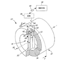
図1は、本発明の渦流量計の実施態様を示す。流量計10は、内孔16を取り囲む壁14を有する導管12を含む。内孔16は、液体又は気体であることができる流体を内孔軸18にほぼ沿って運ぶ。放出バー20は、渦を発生させる障害物である。ピボット部材22が壁14に形成された穴24から内孔16中に延びている。変動する流体圧が放出バー及びピボット部材22に対して作用すると、ピボット部材22がその変動する圧に応答して動く。
FIG. 1 shows an embodiment of the vortex flowmeter of the present invention. The
中心リブ26が穴24の中に配置され、撓曲部28に結合している。撓曲部28は全体的に壁14に結合している。支柱30が撓曲部28から延びている。感知素子32(仮想線で示す)が、好ましくは支柱30への取り付けによって撓曲部28に結合され、ピボット部材22の動きを感知する。感知素子32は、感知した動きを示す出力を生成し、その出力をリード34を介して回路36に伝送する。通常は、回路36は、感知した動きを通信リンク40(2線式、3線式又は4線式ループであってもよいし、ワイヤレス通信リンク40であってもよい)を介して制御中枢38に伝送するように適合されている。
A
好ましい実施態様では、補強リブ42が、撓曲部28の中心線27(又はピボットライン)の各側で撓曲部上に配置されている(参照番号27は図2及び5に示す)。一般に、中心リブ26及び補強リブ42は、内孔軸18の方向に対して平行(流れの方向に対して平行)に延びる。
In a preferred embodiment, reinforcing
一つの実施態様では、補強リブ42は、中心リブ26の中心と、撓曲部28の外側縁との間で撓曲部に配置されている。この位置は、直径Dの撓曲部28を考えることによって定量化することができ、その場合、補強リブ42は、中心リブ26のいずれか側で約0.25Dのところに配置される。代替態様では、補強リブ42は、中心リブ26と撓曲部28の外側縁との間の中央に配置される(たとえば撓曲部28の縁に対して約0.22Dのところ)。この実施態様では、中心リブ26は、支柱30とほぼ同じ幅であり、撓曲部28の直径全体に延びている。代替態様では、中心リブ26は、支柱30よりも何分の1インチ分だけ幅広であり、撓曲部の直径全体に延びる。補強リブは、ほぼ同じ相対的高さ及び幅である。一つの実施態様では、補強リブは、撓曲部の厚さとほぼ同じである高さ及び幅を有する。当業者には、管の壁に適合するために撓曲部28が湾曲しているということが理解されよう。したがって、補強リブ42の高さは、撓曲部28の表面に対する高さであり、ある一定の点に対しては、管の曲率半径にしたがって変動する。
In one embodiment, the reinforcing
実施に依存して、リブのサイズは、異なる圧力及び異なる撓曲部サイズに対応するように調節することができる。さらには、補強リブ42の位置は、中心線に近づく方向又は中心線から離れる方向に調節することもできる。好ましい実施態様では、補強リブ42は、撓曲部28の中心線と撓曲部28の外側縁との間の実質的に中央に配置される。
Depending on the implementation, the rib size can be adjusted to accommodate different pressures and different flexure sizes. Further, the position of the reinforcing
これらの補強リブ42が計器の破裂圧強度を増すということが理解される。補強リブ42を計器に加えると、通常、計器の破裂圧を50%高めることができる。さらには、補強リブ42は、計器10の撓曲部28に加わる圧力のためにセンサに対抗する力を減らすことにより、流体渦から交互に加わる圧力に対する流量計の感度を高める。
It will be understood that these reinforcing
図2は、図1の撓曲部28の拡大図を示す。図示するように、導管12は、撓曲部28が配置される開口24を有している。中心リブ26が撓曲部の直径全体に延び、撓曲部28の中心線44上に配置されている。この実施態様では、補強リブ42は、中心リブ26の各側に配置され、撓曲部28の外側縁まで延びている。補強リブ42は、中心線44と撓曲部28の外側縁との間のほぼ中間点に配置されている。支柱30が、中心リブ26から、導管12から離れる方向に延びている。先に論じたように、好ましい実施態様では、センサは支柱30を介して放出バーに結合されている。
FIG. 2 shows an enlarged view of the
図3は、図1の3−3線から見た渦流量計10の断面を示す。流量計10は、内孔16を取り囲む壁14を有する導管12を含む。内孔16は、液体又は気体であることができる流体を内孔軸18にほぼ沿って運ぶ。放出バー20は、渦を発生させる障害物である。ピボット部材22(図1に示す)が撓曲部28の濡れ側から延びている。変動する流体圧が放出バー及びピボット部材22に対して作用すると、ピボット部材22がその変動する圧に応答して動く。
FIG. 3 shows a cross section of the
この実施態様では、中心リブ26が穴24の中に配置され、撓曲部28に結合している。撓曲部28は全体的に壁14に結合している。支柱30が撓曲部28から延びている。補強リブ42が、撓曲部28の中心線の各側で、中心リブ26の各側で撓曲部上に配置されている。一般に、中心リブ26及び補強リブ42は、内孔軸18の方向に対して平行(流れの方向に対して平行)に延びている。フランジ要素46がトランスミッタハウジング48(仮想線で示す)を計器ボディに結合している。トランスミッタハウジング48はまた、感知したデータを、制御中枢に伝送するための信号へと処理するための回路を含むことができる。
In this embodiment, the
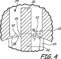
図4は、撓曲部28の拡大断面図を示す。撓曲部28は、導管12内の開口24中に配置されている。中心リブ26が撓曲部28の中心にあり、補強リブ42が中心リブ42と撓曲部28の外周縁との間のほぼ中央にある。中心リブ26及び補強リブ42は、互いに対して平行かつ流体の流れに対して平行に延びている。ピボット部材22が放出バー20に配置され、支柱30に結合されて、支柱30を、ピボット部材22及び放出バー20が受ける流体圧に応答して動かす。
FIG. 4 shows an enlarged cross-sectional view of the
一般に、撓曲部28(厚みを減らした領域)は厚さがTである。補強リブ42は、幅がWであり、高さがHである。撓曲部28は、管壁の湾曲に適合するように湾曲しており、補強リブ42の高さHが撓曲部28の湾曲面に対する高さであることが理解されよう。好ましい実施態様では、幅W及び高さHは厚さTにほぼ等しい。
In general, the flexure 28 (region with reduced thickness) has a thickness T. The reinforcing
図5は、撓曲部28を開口24から見下ろした平面図である。撓曲部28は、撓曲部28の外面(非濡れ面)に沿って縁から縁までで計測される直径がDである。一つの好ましい実施態様では、補強リブ42の位置は、撓曲部28の中心線(ピボットライン)27に対して、補強リブ42が約0.25Dの中央位置に配されるように決定することができる。
FIG. 5 is a plan view of the
先に論じたように、計器の圧力定格を決定する第一の方法は破裂圧試験である。これらの試験では、流量計は、試験装置に接続されたのち、圧力をもはや保持することができなくなって破損するまで加圧される。これらの試験すべてで、もっとも薄い壁の区分である撓曲部区域で破損が起こる。 As discussed above, the first method of determining instrument pressure ratings is the burst pressure test. In these tests, after the flow meter is connected to the test device, it is pressurized until it can no longer hold the pressure and breaks. In all these tests, failure occurs in the flexure area, which is the thinnest wall section.
ASMEコードに関して、計器の安全係数は以下の式によって決定される。 For ASME codes, the instrument safety factor is determined by the following equation:
式中、SFは安全係数であり、Fは鋳造品質係数であり、BPは破裂圧であり、Prは定格圧であり、Tsは材料の引張り強さ規格であり、Taは、鋳造物が取り出された熱からの試験片によって決定される試験材料の実引張り強さである。 Wherein, SF is a safety factor, F is a casting quality factor, BP is bursting pressure, P r is the rated pressure, T s is the intensity standard tensile material, T a is cast The actual tensile strength of the test material as determined by the specimen from the heat from which the object was removed.
補強リブ42を中心線と撓曲部28の縁との間で撓曲部28に加えると、極限破裂圧が著しく高まる。一つの試験例では、補強リブは、幅が約0.035インチであり、高さが0.070インチであり、中心リブ26に対して平行に延びる。補強リブ42は、従来技術の設計では最大合計変位が起こる区域に配置されていた。計算は、30%を超える破裂圧の増大を予測した。試験した装置は50%の破裂圧の改善を示した。
When the reinforcing
補強される撓曲部設計のさらなる解析は、従来の撓曲部設計に対して改善された感度を示した。計算は、感度における約6%の増大を予測した。試験において、補強リブ42は、実施態様によっては、計器の感度を最大20%増大させた。
Further analysis of the reinforced flexure design has shown improved sensitivity over conventional flexure designs. The calculation predicted an approximately 6% increase in sensitivity. In the test, the reinforcing
また、中心リブが、ピボット部材22をその平衡位置に復元しようとする復元力に寄与するということに注目することが重要である。復元力は、ピボット部材の振動の固有周波数を高める傾向にあり、それが、ピボット部材22の固有周波数が、作動中に遭遇する最高渦周波数よりも大きくなることを保証する。補強リブは、実際にこの復元力を改善することができる。
It is also important to note that the central rib contributes to a restoring force that attempts to restore the
さらには、図示する実施態様では、補強リブが厚みを減らした領域のピボット線からオフセットされていることに注目すべきである。好ましい実施態様では、補強リブは、ピボット線と厚みを減らした領域の縁との間のほぼ中間にあり、オフセット距離をほぼ同じにしている。しかし、実施態様によっては、補強リブの位置を変えることが望ましいかもしれない。たとえば、補強リブの位置は、ピボット線と縁との間の中間点からほぼ同じ距離だけオフセットさせることもできる。あるいはまた、補強リブは、補強リブを厚みを減らした領域の特定の位置に配置するため、わずかに異なる距離だけピボット線から離間させることもできる。 Furthermore, it should be noted that in the illustrated embodiment, the reinforcing ribs are offset from the pivot line in the reduced thickness region. In a preferred embodiment, the reinforcing rib is approximately halfway between the pivot line and the edge of the reduced thickness region, and the offset distance is approximately the same. However, in some embodiments it may be desirable to change the position of the reinforcing ribs. For example, the position of the reinforcing rib can be offset by approximately the same distance from the midpoint between the pivot line and the edge. Alternatively, the reinforcing ribs can be separated from the pivot line by a slightly different distance in order to place the reinforcing ribs at specific locations in the reduced thickness region.
最後に、上記は、補強リブがピボット線(又は中心リブ)に対して実質的に平行に延びるものとして記載したが、実施態様によっては、中心線に対する補強リブの角度を変えることが望ましいかもしれない。たとえば、一つの実施態様では、補強リブを、撓曲部で、ピボット線に隣接し、ピボット線から斜めに延びるように配置することが望ましいかもしれない。このような実施態様では、ピボット線又は周縁に対する補強リブの位置は、計測される場所に応じて異なるであろう。角度を変えることにより、改良された圧力保持の利点を維持しながらも計器の感度を調節することが可能である。 Finally, although the above has been described as the reinforcing ribs extending substantially parallel to the pivot line (or center rib), it may be desirable in some embodiments to change the angle of the reinforcing rib relative to the center line. Absent. For example, in one embodiment, it may be desirable to arrange the reinforcing ribs at the flexures, adjacent to the pivot line and extending obliquely from the pivot line. In such an embodiment, the position of the reinforcing rib relative to the pivot line or periphery will vary depending on the location being measured. By changing the angle, it is possible to adjust the sensitivity of the instrument while maintaining the benefits of improved pressure retention.
好ましい実施態様を参照しながら本発明を説明したが、当業者は、本発明の本質及び範囲を逸することなく、形態及び詳細の変更を加えることができることを認識するであろう。 Although the present invention has been described with reference to preferred embodiments, those skilled in the art will recognize that changes in form and detail may be made without departing from the spirit and scope of the invention.
Claims (26)
流体を運ぶための導管、
導管の一部にある厚みを減らした領域、
導管中に配置され、厚みを減らした領域に結合され、流体の流量に応答して、厚みを減らした領域に対し、ピボットラインを中心とする揺動を加えるように構成された放出バー、及び
厚みを減らした領域にあり、ピボットラインから離間され、流体の流れに対して平行に延びる少なくとも一つの補強リブ
を含む渦流量計。A vortex flowmeter for measuring the flow rate of fluid,
Conduit for carrying fluid,
A reduced thickness area in a portion of the conduit,
A discharge bar disposed in the conduit and coupled to the reduced thickness region and configured to apply a swing about the pivot line to the reduced thickness region in response to fluid flow; and A vortex flowmeter comprising at least one reinforcing rib in a reduced thickness region, spaced from the pivot line and extending parallel to the fluid flow.
流体を運ぶための導管、
導管の一部にある厚みを減らした領域、
導管中に配置され、厚みを減らした領域に結合され、流体の流量に応答して、厚みを減らした領域に対し、ピボットラインを中心とする揺動を加えるように構成された放出バー、及び
ピボットラインから離間され、厚みを減らした領域の縁から縁までピボットラインに対して平行に延びる少なくとも一つの補強リブ
を含む渦流量計。A vortex flowmeter for measuring the flow rate of a fluid,
Conduit for carrying fluid,
A reduced thickness area in a portion of the conduit,
A discharge bar disposed in the conduit and coupled to the reduced thickness region and configured to apply a swing about the pivot line to the reduced thickness region in response to fluid flow; and
A vortex flowmeter comprising at least one reinforcing rib spaced from the pivot line and extending parallel to the pivot line from edge to edge of the reduced thickness region.
支柱に結合されてその動きを感知して流量を示す出力を提供するためのセンサ
をさらに含む、請求項14記載の渦流量計。The vortex flowmeter of claim 14, further comprising a strut disposed outside the conduit and coupled to the central rib, and a sensor coupled to the strut to sense its movement and provide an output indicative of the flow rate.
流体を運ぶための導管、
導管の一部に形成された厚みを減らした領域、
導管中に配置され、厚みを減らした領域に結合され、流体の流量に応答して、厚みを減らした領域に対し、ピボットラインを中心とする揺動を加えるように構成された放出バー、及び
厚みを減らした領域にあり、ピボットラインから離間された少なくとも一つの補強リブ
を含む渦流量計。A vortex flowmeter for measuring the flow rate of fluid,
Conduit for carrying fluid,
An area of reduced thickness formed in part of the conduit,
A discharge bar disposed in the conduit and coupled to the reduced thickness region and configured to apply a swing about the pivot line to the reduced thickness region in response to fluid flow; and Ri area near of reduced thickness, vortex flowmeter comprising at least one reinforcing rib spaced from the pivot line.
Applications Claiming Priority (3)
| Application Number | Priority Date | Filing Date | Title |
|---|---|---|---|
| US10/826,510 | 2004-04-16 | ||
| US10/826,510 US6973841B2 (en) | 2004-04-16 | 2004-04-16 | High pressure retention vortex flow meter with reinforced flexure |
| PCT/US2005/010338 WO2005106399A1 (en) | 2004-04-16 | 2005-03-28 | Flow meter for use with high pressure process fluid |
Publications (3)
| Publication Number | Publication Date |
|---|---|
| JP2007532900A JP2007532900A (en) | 2007-11-15 |
| JP2007532900A5 JP2007532900A5 (en) | 2008-05-15 |
| JP4740230B2 true JP4740230B2 (en) | 2011-08-03 |
Family
ID=34965096
Family Applications (1)
| Application Number | Title | Priority Date | Filing Date |
|---|---|---|---|
| JP2007508368A Expired - Fee Related JP4740230B2 (en) | 2004-04-16 | 2005-03-28 | Flowmeter for use with high pressure process fluids |
Country Status (5)
| Country | Link |
|---|---|
| US (1) | US6973841B2 (en) |
| EP (1) | EP1738141B1 (en) |
| JP (1) | JP4740230B2 (en) |
| CN (1) | CN100510652C (en) |
| WO (1) | WO2005106399A1 (en) |
Cited By (1)
| Publication number | Priority date | Publication date | Assignee | Title |
|---|---|---|---|---|
| JP2012504249A (en) * | 2009-12-24 | 2012-02-16 | ローズマウント インコーポレイテッド | Vortex flowmeter with vortex vibration sensor plate |
Families Citing this family (6)
| Publication number | Priority date | Publication date | Assignee | Title |
|---|---|---|---|---|
| EP2064525B1 (en) * | 2006-09-15 | 2010-08-18 | Rosemount, Inc. | Leak check device for vortex sensor replacement |
| US8714028B2 (en) * | 2010-03-01 | 2014-05-06 | Cla-Val Co. | Insertion vortex fluid flow meter with adjustable geometry |
| CA2791407A1 (en) | 2010-03-23 | 2011-09-29 | Avgi Engineering, Inc. | Vortex flow meter |
| US9032815B2 (en) | 2011-10-05 | 2015-05-19 | Saudi Arabian Oil Company | Pulsating flow meter having a bluff body and an orifice plate to produce a pulsating flow |
| CN105333893A (en) * | 2014-08-12 | 2016-02-17 | 丹东东方测控技术股份有限公司 | Structure device applied to self-flowing type fluid ultrasonic measurement |
| CA3031515C (en) | 2016-07-21 | 2021-06-15 | Micro Motion Inc. | Vortex flowmeter with reduced process intrusion |
Citations (3)
| Publication number | Priority date | Publication date | Assignee | Title |
|---|---|---|---|---|
| JPS55101815A (en) * | 1979-01-30 | 1980-08-04 | Oval Eng Co Ltd | Vortex flowmeter |
| JPS61139423A (en) * | 1984-12-13 | 1986-06-26 | Mitsubishi Heavy Ind Ltd | Joining method of fiber reinforced plastics |
| JP3233405B2 (en) * | 1992-10-05 | 2001-11-26 | ローズマウント インコーポレイテッド | Vortex flow meter |
Family Cites Families (39)
| Publication number | Priority date | Publication date | Assignee | Title |
|---|---|---|---|---|
| BE394587A (en) * | 1932-02-25 | |||
| GB823684A (en) | 1954-07-20 | 1959-11-18 | William George Bird | Improvements in or relating to apparatus for the measurement and integration of fluid-velocities |
| US3946608A (en) * | 1974-02-26 | 1976-03-30 | Fischer & Porter Company | Vortex flowmeter with external sensor |
| US4033189A (en) * | 1976-03-26 | 1977-07-05 | Fischer & Porter Co. | External-sensor vortex-type flowmeter |
| GB2008752B (en) * | 1977-11-14 | 1982-03-31 | Yokogawa Electric Works Ltd | Vortex flow meter |
| US4169376A (en) * | 1978-06-26 | 1979-10-02 | Fischer & Porter Company | External sensing system for vortex-type flowmeters |
| US4339957A (en) * | 1980-08-14 | 1982-07-20 | Fischer & Porter Company | Vortex-shedding flowmeter with unitary shedder/sensor |
| US4464939A (en) * | 1982-03-12 | 1984-08-14 | Rosemount Inc. | Vortex flowmeter bluff body |
| JPS58160813A (en) | 1982-03-17 | 1983-09-24 | Yokogawa Hokushin Electric Corp | Vortex flow meter |
| JPS5918422A (en) * | 1982-07-22 | 1984-01-30 | Oval Eng Co Ltd | Vibration compensating device for vortex flowmeter |
| US4520678A (en) * | 1983-09-13 | 1985-06-04 | The Foxboro Company | Small line-size vortex meter |
| US4625564A (en) * | 1983-12-02 | 1986-12-02 | Oval Engineering Co., Ltd. | Vortex flow meter |
| JPH0450493Y2 (en) * | 1985-02-20 | 1992-11-27 | ||
| US4633713A (en) * | 1985-08-23 | 1987-01-06 | Dieterich Standard Corp. | Insert/retract mechanism for flow measurement probes |
| US4645242A (en) * | 1985-08-26 | 1987-02-24 | Dieterich Standard Corp. | High pressure mounting with positive lock |
| US4703659A (en) * | 1985-10-18 | 1987-11-03 | Engineering Measurements Company | Vortex shedding flow meter with noise suppressing and signal enhancing means |
| US4699012A (en) * | 1985-10-18 | 1987-10-13 | Engineering Measurements Company | Vortex shedding flow meter with stress concentration signal enhancement |
| US4782710A (en) * | 1986-04-30 | 1988-11-08 | Fuji Electric Co., Ltd. | Karman vortex flow meter |
| US4717159A (en) * | 1986-06-06 | 1988-01-05 | Dieterich Standard Corp. | Method and apparatus for seating and sealing a pitot tube type flow meter in a pipe |
| US4884458A (en) * | 1986-10-20 | 1989-12-05 | Lew Hyok S | High sensitivity vortex shedding flowmeter |
| US4911019A (en) * | 1986-10-30 | 1990-03-27 | Lew Hyok S | High sensitivity-high resonance frequency vortex shedding flowmeter |
| US4803870A (en) * | 1987-02-09 | 1989-02-14 | Lew Hyok S | Vortex shedding flowmeter with mechanically amplifying pressure sensor |
| US4973062A (en) * | 1986-10-30 | 1990-11-27 | Lew Hyok S | Vortex flowmeter |
| US4706503A (en) * | 1987-01-30 | 1987-11-17 | Itt Corporation | Vortex meter sensor |
| US4972723A (en) * | 1987-02-09 | 1990-11-27 | Lew Hyok S | Vortex generator-sensor |
| US4926532A (en) * | 1987-06-03 | 1990-05-22 | Phipps Jackie M | Method of manufacturing a flow meter |
| US4791818A (en) * | 1987-07-20 | 1988-12-20 | Itt Corporation | Cantilever beam, insertable, vortex meter sensor |
| US4926695A (en) * | 1987-09-15 | 1990-05-22 | Rosemount Inc. | Rocking beam vortex sensor |
| US4891990A (en) * | 1987-12-04 | 1990-01-09 | Schlumberger Industries, Inc. | Vortex flowmeter transducer |
| US4835436A (en) * | 1988-03-21 | 1989-05-30 | Lew Hyok S | Piezoelectric impulse sensor |
| US4884441A (en) * | 1988-05-11 | 1989-12-05 | Lew Hyok S | Variable capacity flowmeter |
| US5095760A (en) * | 1989-05-08 | 1992-03-17 | Lew Hyok S | Vortex flowmeter with dual sensors |
| US5036040A (en) * | 1989-06-20 | 1991-07-30 | Eastman Kodak Company | Infrared absorbing nickel-dithiolene dye complexes for dye-donor element used in laser-induced thermal dye transfer |
| US4984471A (en) * | 1989-09-08 | 1991-01-15 | Fisher Controls International, Inc. | Force transmitting mechanism for a vortex flowmeter |
| US5109704A (en) * | 1989-09-26 | 1992-05-05 | Lew Hyok S | Vortex flowmeter with balanced vortex sensor |
| US5076105A (en) * | 1989-09-26 | 1991-12-31 | Lew Hyok S | Vortex flowmeter |
| US5197336A (en) * | 1990-01-29 | 1993-03-30 | Fuji Electric Co., Ltd. | Karman vortex flow meter |
| US6170338B1 (en) * | 1997-03-27 | 2001-01-09 | Rosemont Inc. | Vortex flowmeter with signal processing |
| US6053053A (en) * | 1998-03-13 | 2000-04-25 | Rosemount Inc. | Multiple vortex flowmeter system |
-
2004
- 2004-04-16 US US10/826,510 patent/US6973841B2/en not_active Expired - Lifetime
-
2005
- 2005-03-28 WO PCT/US2005/010338 patent/WO2005106399A1/en not_active Application Discontinuation
- 2005-03-28 JP JP2007508368A patent/JP4740230B2/en not_active Expired - Fee Related
- 2005-03-28 EP EP05733073.0A patent/EP1738141B1/en active Active
- 2005-03-28 CN CNB2005800113973A patent/CN100510652C/en active Active
Patent Citations (3)
| Publication number | Priority date | Publication date | Assignee | Title |
|---|---|---|---|---|
| JPS55101815A (en) * | 1979-01-30 | 1980-08-04 | Oval Eng Co Ltd | Vortex flowmeter |
| JPS61139423A (en) * | 1984-12-13 | 1986-06-26 | Mitsubishi Heavy Ind Ltd | Joining method of fiber reinforced plastics |
| JP3233405B2 (en) * | 1992-10-05 | 2001-11-26 | ローズマウント インコーポレイテッド | Vortex flow meter |
Cited By (1)
| Publication number | Priority date | Publication date | Assignee | Title |
|---|---|---|---|---|
| JP2012504249A (en) * | 2009-12-24 | 2012-02-16 | ローズマウント インコーポレイテッド | Vortex flowmeter with vortex vibration sensor plate |
Also Published As
| Publication number | Publication date |
|---|---|
| CN100510652C (en) | 2009-07-08 |
| US6973841B2 (en) | 2005-12-13 |
| WO2005106399A1 (en) | 2005-11-10 |
| CN1942741A (en) | 2007-04-04 |
| EP1738141B1 (en) | 2018-01-03 |
| US20050229715A1 (en) | 2005-10-20 |
| EP1738141A1 (en) | 2007-01-03 |
| JP2007532900A (en) | 2007-11-15 |
Similar Documents
| Publication | Publication Date | Title |
|---|---|---|
| JP4740230B2 (en) | Flowmeter for use with high pressure process fluids | |
| US6802224B2 (en) | Arch-shaped tube type coriolis meter and method for determining shape of the coriolis meter | |
| US4791818A (en) | Cantilever beam, insertable, vortex meter sensor | |
| US4989456A (en) | Variable area obstruction gas flow meter | |
| JP3554347B2 (en) | Flowmeter | |
| JP5346423B2 (en) | Flanged vortex flowmeter with integral taper diameter expansion | |
| US5357811A (en) | Single tube coriolis flow meter with floating intermediate section | |
| US5343762A (en) | Vortex flowmeter | |
| JP2005529307A (en) | Vibration type measuring instrument | |
| US20060207658A1 (en) | Offset variable-orifice flow sensor | |
| JP7271044B2 (en) | coriolis flow sensor assembly | |
| US7726202B2 (en) | Tertiary mode vibration type coriolis flowmeter | |
| ATE482378T1 (en) | CORIOLIS MASS FLOW METER AND METHOD FOR MANUFACTURE THEREOF | |
| JP3782421B2 (en) | Coriolis flow meter | |
| US4116059A (en) | Multi-range vortex-type flowmeter | |
| WO2016141628A1 (en) | Mass flow sensor | |
| JP5162593B2 (en) | Leak inspection device for vortex sensor replacement | |
| JP2869054B1 (en) | Insertion type vortex flowmeter and method for determining its probe line length | |
| US5033313A (en) | Inertia force flowmeter | |
| JP3782422B2 (en) | Coriolis flow meter | |
| JP3645855B2 (en) | Arcuate Coriolis Meter and Shape Determination Method | |
| JP4562497B2 (en) | Noise suppression type straight pipe type Coriolis flow meter | |
| JP3182718B2 (en) | Temperature detector for differential pressure flow meter and its protection tube | |
| JPH02107925A (en) | Flowmeter | |
| SU315039A1 (en) |
Legal Events
| Date | Code | Title | Description |
|---|---|---|---|
| A521 | Written amendment |
Free format text: JAPANESE INTERMEDIATE CODE: A523 Effective date: 20080327 |
|
| A621 | Written request for application examination |
Free format text: JAPANESE INTERMEDIATE CODE: A621 Effective date: 20080327 |
|
| A131 | Notification of reasons for refusal |
Free format text: JAPANESE INTERMEDIATE CODE: A131 Effective date: 20101207 |
|
| A521 | Written amendment |
Free format text: JAPANESE INTERMEDIATE CODE: A523 Effective date: 20110303 |
|
| TRDD | Decision of grant or rejection written | ||
| A01 | Written decision to grant a patent or to grant a registration (utility model) |
Free format text: JAPANESE INTERMEDIATE CODE: A01 Effective date: 20110405 |
|
| A61 | First payment of annual fees (during grant procedure) |
Free format text: JAPANESE INTERMEDIATE CODE: A61 Effective date: 20110428 |
|
| R150 | Certificate of patent or registration of utility model |
Ref document number: 4740230 Country of ref document: JP Free format text: JAPANESE INTERMEDIATE CODE: R150 Free format text: JAPANESE INTERMEDIATE CODE: R150 |
|
| FPAY | Renewal fee payment (event date is renewal date of database) |
Free format text: PAYMENT UNTIL: 20140513 Year of fee payment: 3 |
|
| R250 | Receipt of annual fees |
Free format text: JAPANESE INTERMEDIATE CODE: R250 |
|
| R250 | Receipt of annual fees |
Free format text: JAPANESE INTERMEDIATE CODE: R250 |
|
| R250 | Receipt of annual fees |
Free format text: JAPANESE INTERMEDIATE CODE: R250 |
|
| S111 | Request for change of ownership or part of ownership |
Free format text: JAPANESE INTERMEDIATE CODE: R313113 |
|
| S531 | Written request for registration of change of domicile |
Free format text: JAPANESE INTERMEDIATE CODE: R313531 |
|
| R350 | Written notification of registration of transfer |
Free format text: JAPANESE INTERMEDIATE CODE: R350 |
|
| R250 | Receipt of annual fees |
Free format text: JAPANESE INTERMEDIATE CODE: R250 |
|
| R250 | Receipt of annual fees |
Free format text: JAPANESE INTERMEDIATE CODE: R250 |
|
| R250 | Receipt of annual fees |
Free format text: JAPANESE INTERMEDIATE CODE: R250 |
|
| R250 | Receipt of annual fees |
Free format text: JAPANESE INTERMEDIATE CODE: R250 |
|
| LAPS | Cancellation because of no payment of annual fees |