JP4732944B2 - Disk unit - Google Patents

Disk unit Download PDF

Info

Publication number
JP4732944B2
JP4732944B2 JP2006106188A JP2006106188A JP4732944B2 JP 4732944 B2 JP4732944 B2 JP 4732944B2 JP 2006106188 A JP2006106188 A JP 2006106188A JP 2006106188 A JP2006106188 A JP 2006106188A JP 4732944 B2 JP4732944 B2 JP 4732944B2
Authority
JP
Japan
Prior art keywords
disk
disc
guide
lever
diameter
Prior art date
Legal status (The legal status is an assumption and is not a legal conclusion. Google has not performed a legal analysis and makes no representation as to the accuracy of the status listed.)
Expired - Fee Related
Application number
JP2006106188A
Other languages
Japanese (ja)
Other versions
JP2007280525A (en
Inventor
則勝 吉田
正徳 大西
Current Assignee (The listed assignees may be inaccurate. Google has not performed a legal analysis and makes no representation or warranty as to the accuracy of the list.)
Panasonic Corp
Panasonic Holdings Corp
Original Assignee
Panasonic Corp
Matsushita Electric Industrial Co Ltd
Priority date (The priority date is an assumption and is not a legal conclusion. Google has not performed a legal analysis and makes no representation as to the accuracy of the date listed.)
Filing date
Publication date
Application filed by Panasonic Corp, Matsushita Electric Industrial Co Ltd filed Critical Panasonic Corp
Priority to JP2006106188A priority Critical patent/JP4732944B2/en
Priority to US11/727,786 priority patent/US7685612B2/en
Priority to CN2007100890361A priority patent/CN101051494B/en
Publication of JP2007280525A publication Critical patent/JP2007280525A/en
Application granted granted Critical
Publication of JP4732944B2 publication Critical patent/JP4732944B2/en
Expired - Fee Related legal-status Critical Current
Anticipated expiration legal-status Critical

Links

Images

Classifications

    • GPHYSICS
    • G11INFORMATION STORAGE
    • G11BINFORMATION STORAGE BASED ON RELATIVE MOVEMENT BETWEEN RECORD CARRIER AND TRANSDUCER
    • G11B17/00Guiding record carriers not specifically of filamentary or web form, or of supports therefor
    • G11B17/02Details
    • G11B17/022Positioning or locking of single discs
    • G11B17/028Positioning or locking of single discs of discs rotating during transducing operation
    • G11B17/0288Positioning or locking of single discs of discs rotating during transducing operation by means for moving the turntable or the clamper towards the disk
    • GPHYSICS
    • G11INFORMATION STORAGE
    • G11BINFORMATION STORAGE BASED ON RELATIVE MOVEMENT BETWEEN RECORD CARRIER AND TRANSDUCER
    • G11B17/00Guiding record carriers not specifically of filamentary or web form, or of supports therefor
    • G11B17/02Details
    • G11B17/022Positioning or locking of single discs
    • G11B17/028Positioning or locking of single discs of discs rotating during transducing operation
    • G11B17/0284Positioning or locking of single discs of discs rotating during transducing operation by clampers
    • G11B17/0286Positioning or locking of single discs of discs rotating during transducing operation by clampers mounted on a pivotal lever
    • GPHYSICS
    • G11INFORMATION STORAGE
    • G11BINFORMATION STORAGE BASED ON RELATIVE MOVEMENT BETWEEN RECORD CARRIER AND TRANSDUCER
    • G11B17/00Guiding record carriers not specifically of filamentary or web form, or of supports therefor
    • G11B17/02Details
    • G11B17/04Feeding or guiding single record carrier to or from transducer unit
    • G11B17/05Feeding or guiding single record carrier to or from transducer unit specially adapted for discs not contained within cartridges
    • G11B17/051Direct insertion, i.e. without external loading means

Description

本発明は、CDやDVD等のディスク状の記録媒体(以下、ディスクという)を装置内に搬送し、ディスク記録再生位置に装着して、情報の記録及び再生を行うディスク装置に関する。   The present invention relates to a disk apparatus for recording and reproducing information by transporting a disk-shaped recording medium (hereinafter referred to as a disk) such as a CD or DVD into the apparatus and mounting it at a disk recording / reproducing position.

トレイを用いずにディスク装置内にディスクをローディングする機構として、スロットインローディング機構が知られている。この機構は、ディスク装置に挿入されるディスクの一部を長尺のゴムローラと、ゴムローラと対向する位置に設けられたガイド部材とで弾性的に挟持し、その状態でゴムローラを回転させることによりディスクを装置の内部に引き込み、ディスク記録再生位置にセットする機構である。このようなスロットインローディング機構の従来例としては、例えば特許文献1(特開2002−140850号公報)や特許文献2(特開2003−059151号公報)に開示されたものがある。   A slot-in loading mechanism is known as a mechanism for loading a disk into a disk device without using a tray. In this mechanism, a part of a disk inserted into the disk device is elastically sandwiched between a long rubber roller and a guide member provided at a position facing the rubber roller, and the rubber roller is rotated in this state to rotate the disk. Is pulled into the device and set at the disk recording / reproducing position. As conventional examples of such a slot inloading mechanism, for example, there are those disclosed in Patent Document 1 (Japanese Patent Laid-Open No. 2002-140850) and Patent Document 2 (Japanese Patent Laid-Open No. 2003-059151).

特許文献1の装置において、ディスク挿入口近傍に設けられ、ゴムローラと協働してディスクの搬送方向の移動(挿入及び排出)を案内するディスクガイドは、ディスクより柔らかい合成樹脂(プラスチック)で形成されており、特許文献1の図16、図17に示されるように、金属の板金に保持されて剛性を保っている。このディスクガイドを形成する合成樹脂の例としては、特許文献3(特開2005−050440号公報)に開示されているような、ディスクに傷を付け難い構造を有するポリアセタール樹脂組成物が挙げられる。   In the apparatus of Patent Document 1, a disk guide provided in the vicinity of a disk insertion opening and guiding movement (insertion and ejection) in the conveyance direction of a disk in cooperation with a rubber roller is formed of a synthetic resin (plastic) softer than the disk. As shown in FIG. 16 and FIG. 17 of Patent Document 1, it is held by a metal sheet metal to maintain rigidity. As an example of the synthetic resin for forming the disk guide, there is a polyacetal resin composition having a structure that is difficult to damage the disk as disclosed in Patent Document 3 (Japanese Patent Laid-Open No. 2005-050440).

一方、特許文献2の装置において用いられるディスクガイドは、樹脂ではなく、特許文献2の図3に示すように、外側に向かうに従いゴムローラに近づくように山形に突出する突条を複数、有するように形成された金属の板金で構成されている。これにより、薄型化、部品点数削減がなされている。   On the other hand, the disk guide used in the apparatus of Patent Document 2 is not resin, but has a plurality of protrusions protruding in a mountain shape so as to approach the rubber roller toward the outside as shown in FIG. 3 of Patent Document 2. It is composed of a formed metal sheet metal. Thereby, the thickness is reduced and the number of parts is reduced.

特開2002−140850号公報JP 2002-140850 A 特開2003−059151号公報JP 2003-059151 A 特開2005−050440号公報JP 2005-050440 A

特許文献2の装置においては、ディスクガイドが金属の板金で形成されているために、ディスクガイドが当接するディスクの、記録面とは反対側の面、つまりレーベル面に傷をつける恐れがある。特にCD等のレーベル印刷の薄いディスクにおいては、レーベル面側に記録されたピットがあるため、傷が深くなるとエラーレートが増大して、再生に悪影響が生じる。   In the apparatus of Patent Document 2, since the disc guide is formed of a metal sheet metal, there is a risk of scratching the surface opposite to the recording surface, that is, the label surface, of the disc with which the disc guide abuts. In particular, in a label-printed thin disk such as a CD, since there are pits recorded on the label surface side, the error rate increases when the flaw becomes deep, which adversely affects reproduction.

ディスクの傷を防ぐ手段としては、例えば、ディスクに塗装やコーティング等を施す手段が考えられる。しかしながら、ディスクに塗装やコーティング等を施すと、ディスクの摩擦係数が上がり、ゴムローラのディスク搬送力が伝わりにくくなる不具合が発生する。ゴムローラのディスク搬送力を上げるために、ゴムローラがディスクをディスクガイドに押し付ける押圧力を上げると、さらにディスクがディスクガイドに擦り付けられることになるため、傷が付き易くなる。結局、前記手段では、ディスクに傷を付き難くすることができない。   As a means for preventing the disc from being scratched, for example, a means for painting or coating the disc can be considered. However, if the disk is painted or coated, the coefficient of friction of the disk increases, causing a problem that it is difficult to transmit the disk conveying force of the rubber roller. If the pressing force by which the rubber roller presses the disk against the disk guide is increased in order to increase the disk conveying force of the rubber roller, the disk is further rubbed against the disk guide, so that the disk is easily damaged. After all, the above means cannot make it difficult to scratch the disc.

また、使用者がディスクの記録面とレーベル面を逆に挿入するなどの不慮の操作により、ディスクに傷をつける恐れもある。さらに、近年、両面に記録面があるディスクも増えてきている。このため、ディスクガイドの材質としては、特許文献1及び3に示されるように、ディスクに傷を付け難い構造を有するポリアセタール等の合成樹脂を用いることが適している。   In addition, there is a possibility that the disc may be damaged by an inadvertent operation such as inserting the recording surface and the label surface of the disc in reverse. Furthermore, in recent years, an increasing number of disks have recording surfaces on both sides. For this reason, as a material of the disk guide, as shown in Patent Documents 1 and 3, it is suitable to use a synthetic resin such as polyacetal having a structure that does not easily damage the disk.

しかしながら、ディスクガイドにディスクより柔らかい材質のものを用いたとしても、ディスクガイドとディスクとが接触すると、その隙間に、空気中に舞っている埃や、静電気でディスクに付着した埃、成形時にディスクの外周に形成されたバリが落ちた粒等の、ディスクより硬い又は同じ硬度の物質が挟まれて、ディスクを傷つける可能性がある。このため、ディスクガイドとディスクの記録面又はレーベル面(以下、ディスクの内側という)との隙間をある程度確保する必要がある。この隙間を大きくし過ぎると、装置が大型化してしまうため、通常、この隙間はディスクに対してディスクガイドを1度程度(5mmの距離に対して90μm)傾斜させることによって形成することが好ましいとされている。そこで、特許文献2の装置のように、外側に向かうに従いゴムローラに近づくように山形に突出する突条を設けることによって、前記傾斜角を形成することが考えられる。しかしながら、合成樹脂で形成したディスクガイドに前記突条を設けると、前記突条を設けた部分の肉厚が増すために、ディスクガイドの成形時にヒケ等の変形が生じやすい一方、ディスク自体も、前記突条を設けた部分からの押圧力によって、変形してディスクガイドに近づく方向に反りが生じやすい。また、逆にディスクガイドの中央側は、肉厚が薄くなるため、反りが発生しやすく、簡単に浮きが生じる。また、ディスクガイドは、規格直径12cmのディスク(以下、大径ディスクという)と同程度の長さを有し、比較的長尺な部材であるため、反りや反りによる浮きが生じやすい。このため、ディスクガイドとディスクの内側との隙間を確保することが難しく、ディスクの内側の傷を防ぐことは困難である。   However, even if a disc guide made of a material softer than the disc is used, when the disc guide comes into contact with the disc, dust that floats in the air, dust that adheres to the disc due to static electricity, There is a possibility that a material harder than or having the same hardness as the disk, such as a grain having a burr formed on the outer periphery of the disk, may be sandwiched and damage the disk. For this reason, it is necessary to secure a certain gap between the disc guide and the recording surface or label surface of the disc (hereinafter referred to as the inside of the disc). If this gap is made too large, the apparatus becomes larger, and it is usually preferable to form this gap by tilting the disk guide about 1 degree (90 μm for a distance of 5 mm) with respect to the disk. Has been. Therefore, it is conceivable to form the inclination angle by providing a protrusion that protrudes in a mountain shape so as to approach the rubber roller as it goes outward as in the device of Patent Document 2. However, when the protrusion is provided on the disk guide formed of synthetic resin, the thickness of the portion provided with the protrusion increases, so that deformation such as sink marks is likely to occur when the disk guide is molded, while the disk itself is also Due to the pressing force from the portion provided with the ridge, warping tends to occur in the direction of deformation and approaching the disk guide. On the other hand, the thickness of the center side of the disk guide is reduced, so that warpage is likely to occur and the float easily occurs. In addition, the disc guide has a length comparable to that of a disc having a standard diameter of 12 cm (hereinafter referred to as a large-diameter disc) and is a relatively long member, so that the disc guide is likely to be bent due to warpage or warpage. For this reason, it is difficult to secure a gap between the disc guide and the inside of the disc, and it is difficult to prevent scratches on the inside of the disc.

また、ディスクガイドを固定部材に係合することによって固定する場合には、ディスクガイドの係合部と固定部材との間にある程度の隙間が必要である。しかしながら、ディスクガイドの係合部と固定部材との間に隙間を設けると、その隙間によって、ディスクガイドは固定部材とガタを生じた状態で固定されることとなるため、再生又は記録中のディスクの回転により発生する振動によってノイズを生じることがある。   Further, when the disk guide is fixed by being engaged with the fixing member, a certain gap is required between the engaging portion of the disk guide and the fixing member. However, if a gap is provided between the engaging portion of the disc guide and the fixing member, the disc guide is fixed with the fixing member and the backlash generated by the gap. Noise may be generated by vibration generated by rotation of the.

従って、本発明の目的は、前記課題を解決することにあって、トレイを用いずに装置内にディスクをローディングするスロットインローディング機構において、ディスクを装置内へ案内するディスクガイドによってディスクの内側に傷がつかないようにするとともに、ディスクガイドをガタつきなく固定したディスク装置を提供することにある。   Accordingly, an object of the present invention is to solve the above-mentioned problem, and in a slot-in loading mechanism for loading a disk into the apparatus without using a tray, the disk guide that guides the disk into the apparatus is provided inside the disk. It is an object of the present invention to provide a disk device in which the disk guide is fixed without rattling while preventing damage.

前記目的を達成するために、本発明は以下のように構成する。
本発明の第1態様によれば、ディスクを挿入するディスク挿入口が一側面に形成された筐体と、
前記筐体内に配設され、前記ディスク挿入口から挿入される前記ディスクと当接して、前記ディスクのディスク挿入方向の移動を案内するディスクガイドと、
前記筐体内に配設され、前記ディスクガイドと協働して、前記筐体内のディスク記録再生位置に対向するディスク装着準備位置に前記ディスクを搬送するディスク搬送装置と、
前記筐体内に配設され、前記ディスク装着準備位置に搬送された前記ディスクを前記ディスク記録再生位置に装着するディスククランプ装置と、
前記筐体内に配設され、前記ディスク記録再生位置に装着された前記ディスクを再生又は、記録及び再生する記録再生装置と、
を備えるディスク装置であって、
前記ディスクガイドは、
前記ディスク挿入方向に対して交差方向に延在し、挿入時の前記ディスクに当接可能なディスク当接面を有して、前記ディスク当接面により前記ディスクの前記ディスク挿入方向の移動を案内する板状のガイド部材と、
前記ガイド部材の前記ディスク当接面と反対側面で且つ延在方向のそれぞれの端部近傍に設けられた凸部と、
前記ガイド部材の前記ディスク当接面と反対側面で且つ前記凸部より前記延在方向の中央部側に設けられた係合部と、
を備えており、
当該ディスクガイドは、前記交差方向に延在するように前記筐体内に配設された板状のディスクガイド固定部材に、前記係合部が係合して固定されるとともに前記凸部が当接することにより、前記ガイド部材の延在方向の中央部からそれぞれの端部に向かうに従い、前記ディスクガイド固定部材から遠ざかる方向に傾斜角度を増しながら傾斜して、前記ディスクガイド部材のディスク当接面が、挿入時の前記ディスクの外周部近傍でのみ当接可能であることを特徴とするディスク装置を提供する。
In order to achieve the above object, the present invention is configured as follows.
According to the first aspect of the present invention, a housing in which a disk insertion slot for inserting a disk is formed on one side surface;
A disk guide disposed in the housing and abutting on the disk inserted from the disk insertion port to guide the movement of the disk in the disk insertion direction;
A disk transport device that is disposed in the housing and transports the disk to a disk mounting preparation position facing the disk recording / reproducing position in the housing in cooperation with the disk guide;
A disk clamping device for mounting the disk, which is disposed in the housing and transported to the disk mounting preparation position, to the disk recording / reproducing position;
A recording / reproducing apparatus that is arranged in the casing and reproduces or records and reproduces the disc mounted at the disc recording / reproducing position;
A disk device comprising:
The disc guide is
A disk contact surface extending in a direction intersecting the disk insertion direction and capable of contacting the disk at the time of insertion, and guides movement of the disk in the disk insertion direction by the disk contact surface. A plate-shaped guide member,
Convex portions provided on the side surface opposite to the disk contact surface of the guide member and in the vicinity of each end portion in the extending direction;
An engaging portion provided on a side surface opposite to the disk contact surface of the guide member and on a central portion side in the extending direction from the convex portion ;
With
The disc guide is fixed by engaging the engaging portion with a plate-like disc guide fixing member disposed in the casing so as to extend in the intersecting direction, and the convex portion abuts. Accordingly, the disk contact surface of the disk guide member is inclined while increasing the inclination angle in the direction away from the disk guide fixing member as it goes from the center part in the extending direction of the guide member to each end part. The disc device is characterized in that it can contact only in the vicinity of the outer periphery of the disc when inserted.

本発明の第2態様によれば、前記ディスクガイドの前記ガイド部材は、単一の板状の部材で構成され、前記ディスクガイドの前記係合部は、前記ガイド部材の延在方向の中央部と前記凸部との間に設けられていることを特徴とする第1態様に記載のディスク装置を提供する。   According to the second aspect of the present invention, the guide member of the disc guide is formed of a single plate-like member, and the engaging portion of the disc guide is a central portion in the extending direction of the guide member. The disc device according to the first aspect is provided between the projection and the convex portion.

本発明の第3態様によれば、前記ディスクガイドの前記ガイド部材は、前記延在方向の中央部に対する両側に配設された2つの板状の部材で構成され、前記ディスクガイドの前記係合部は、前記ガイド部材の延在方向の中央部側のそれぞれの端部に設けられていることを特徴とする第1態様に記載のディスク装置を提供する。   According to a third aspect of the present invention, the guide member of the disc guide is composed of two plate-like members disposed on both sides with respect to the central portion in the extending direction, and the engagement of the disc guide The part is provided at each end on the center side in the extending direction of the guide member. The disk device according to the first aspect is provided.

本発明の第4態様によれば、前記ディスクガイドの前記凸部に代えて、前記凸部と同じ位置に、前記ディスクガイド固定部材が前記ディスクガイドの取付け側の面に凸部を備え、
前記ディスクガイド固定部材の前記ディスクガイドの取付け側の面に前記ディスクガイドの前記係合部が係合して固定されるとともに、前記ディスクガイド固定部材の前記凸部が前記ディスクガイドの前記ガイド部材に当接することにより、前記ガイド部材が、前記ガイド部材の延在方向の中央部からそれぞれの端部に向かうに従い、前記ディスクガイド固定部材から遠ざかる方向に傾斜して、挿入時の前記ディスクの外周部近傍でのみ当接可能であることを特徴とする第1態様に記載のディスク装置を提供する。
According to the fourth aspect of the present invention, instead of the convex portion of the disc guide, the disc guide fixing member has a convex portion on the mounting side surface of the disc guide at the same position as the convex portion,
The engaging portion of the disc guide is engaged and fixed to a surface of the disc guide fixing member on the mounting side of the disc guide, and the convex portion of the disc guide fixing member is the guide member of the disc guide. The guide member is inclined in a direction away from the disc guide fixing member as it goes from the central portion in the extending direction of the guide member to each end portion, and the outer periphery of the disc at the time of insertion The disc device according to the first aspect is provided that can be contacted only in the vicinity of the portion.

本発明の第4態様によれば、前記ディスククランプ装置は、
前記ディスク装着準備位置に搬送された前記ディスクに当接して、ターンテーブル面の前記ディスク記録再生位置に前記ディスクを押圧するクランパと、
前記交差方向に延在するように配設されるとともに、前記ディスク挿入口側を回動中心として回動自在に前記筐体に固定され、前記クランパを支持するとともに前記ディスクガイド固定部材を備えるクランプユニットと、
前記ディスク搬送装置による前記ディスクの搬送時には、前記クランパを前記ディスク装着準備位置に退避させて、前記ガイド部材の前記ディスク当接面が前記ディスク挿入口から挿入される前記ディスクに当接可能とし、前記ディスクの装着時には、前記クランパを前記ディスク記録再生位置に移動させるように前記クランプユニットを回動させて、前記ガイド部材の前記ディスク当接面から前記ディスクを退避させる駆動機構を備え、
前記ディスクガイドの前記ガイド部材は、
前記延在方向のそれぞれの端部近傍に、幅方向における前記ディスク挿入方向の下流側に向かうに従い、前記ディスク当接面は前記ディスクガイド固定部材に近づく方向に傾斜する傾斜面を有し、
前記傾斜面は、前記クランパが前記ディスク記録再生位置に移動して、前記ディスクが前記ディスク記録再生位置に装着された際において、当該ディスクが前記ターンテーブル面に対してほぼ平行に保持された状態では、当該ディスクの面より離れていると共に当該ディスクの面に対して傾斜状態にあり、前記ディスクが、前記ガイド部材の前記ディスク当接面に当接する状態に浮き上がって前記ターンテーブル面に対して傾斜した状態では、当該ディスクの面と、ほぼ平行または前記ディスク挿入方向の下流側の部分のみが当接するように構成したことを特徴とする第1態様〜第4態様のいずれか1つに記載のディスク装置を提供する。
According to a fourth aspect of the present invention, the disc clamping device comprises:
A clamper that abuts on the disk conveyed to the disk mounting preparation position and presses the disk to the disk recording / playback position on the turntable surface;
A clamp that is disposed so as to extend in the intersecting direction, is fixed to the housing so as to be rotatable about the disc insertion opening side, supports the clamper, and includes the disc guide fixing member. Unit,
When the disk is transported by the disk transport device, the disker is retracted to the disk mounting preparation position so that the disk contact surface of the guide member can contact the disk inserted from the disk insertion port, A drive mechanism for rotating the clamp unit to move the clamper to the disk recording / reproducing position and retracting the disk from the disk contact surface of the guide member when the disk is mounted;
The guide member of the disc guide is
In the vicinity of each end in the extending direction, the disk contact surface has an inclined surface that is inclined in a direction approaching the disk guide fixing member as it goes downstream in the disk insertion direction in the width direction.
The inclined surface is a state where the disc is held substantially parallel to the turntable surface when the clamper moves to the disc recording / reproducing position and the disc is mounted at the disc recording / reproducing position. Then, the disk is separated from the surface of the disk and is inclined with respect to the surface of the disk, and the disk floats in a state of contacting the disk abutting surface of the guide member to the surface of the turntable. In any one of the first to fourth aspects, the disk is configured to be in contact with the surface of the disk substantially parallel or only in the downstream side in the disk insertion direction in the inclined state. A disk device is provided.

本発明の第1態様によれば、ディスクガイドが、板状のガイド部材と、ガイド部材の延在方向のそれぞれの端部近傍に設けられた凸部と、ガイド部材に設けられた係合部とを備え、板状のディスクガイド固定部材に、前記係合部が係合するとともに前記凸部が当接することにより、ガイド部材の延在方向の中心部がガイド固定部材側に反って、ガイド部材の延在方向の中央部からそれぞれの端部に向かうに従い、ディスク固定部材から遠ざかる方向に傾斜が増して、ディスクの外周近傍でのみ当接可能であるので、ディスクガイドによってディスクの内側に傷がつかない。また、ディスクガイドは、ディスクガイド固定部に係合部で係合し、凸部で当接することによって、ディスクガイド固定部に対して反った状態で取り付けられるので、ガイド部材の成形時にガイド部材に反りが生じても、そのガイド部材の反りよりもディスクガイドは大きく反り、その大きな反りにより弾性力が生じて、確実にディスクガイドはディスクガイド固定部にガタ無く固定され、浮きも生じない。したがって、ガタが抑えられるため、再生又は記録中のディスクの回転振動に対しても異音を発生することが無い。
また、ガイド部材にヒケ、反りが生じて傾斜が減少しても、凸部によってガイド部材の延在方向の中心部がガイド固定部材側に反ることにより、必要な傾斜角度を確保することが可能で、ディスクの内側に傷を生じることが無い。
According to the first aspect of the present invention, the disk guide includes a plate-shaped guide member, a convex portion provided in the vicinity of each end portion in the extending direction of the guide member, and an engaging portion provided in the guide member. When the engaging portion engages with the plate-shaped disc guide fixing member and the convex portion abuts, the center portion in the extending direction of the guide member warps toward the guide fixing member side, and the guide Since the inclination increases in the direction away from the disk fixing member as it goes from the center in the extending direction of the member to each end, it can be contacted only in the vicinity of the outer periphery of the disk. I can't. In addition, the disc guide is attached in a state of being warped with respect to the disc guide fixing portion by engaging the disc guide fixing portion with the engaging portion and abutting with the convex portion. Even if the warp occurs, the disc guide warps more greatly than the warp of the guide member, and an elastic force is generated by the large warp, so that the disc guide is securely fixed to the disc guide fixing portion without play and no floating occurs. Accordingly, since the play is suppressed, no abnormal noise is generated even with respect to the rotational vibration of the disc during reproduction or recording.
Further, even if the guide member is sinked or warped, and the inclination is reduced, the center portion in the extending direction of the guide member is warped toward the guide fixing member by the convex portion, so that a necessary inclination angle can be secured. This is possible and does not cause scratches inside the disc.

また、特許文献1、2及び3の装置においては、記録又は再生中の装置に、移動等による衝撃や急な動作が生じると、回転するディスクのジャイロ効果により、ディスクがディスク記録再生位置から離れて浮いてしまうことがある。このとき、ディスクの一面のエッジ部分がガイド部材に衝突するが、特許文献2の装置のように、ガイド部材が金属で形成されている場合には、非常に大きい不快な音が生じる。また、特許文献1及び3の装置のように、ガイド部材がディスクより柔らかい樹脂で形成されている場合、衝突音は柔らかであるが、ディスクの一面のエッジによりディスクガイドが削られて、ディスクを排出する際に、その削られた部分にディスクが引っかかり排出できないという不具合を生じる。   In addition, in the devices of Patent Documents 1, 2, and 3, when a shock or a sudden operation due to movement or the like occurs in the recording or reproducing device, the disk is separated from the disk recording / reproducing position due to the gyro effect of the rotating disk. May float. At this time, the edge portion of one surface of the disk collides with the guide member. However, when the guide member is made of metal as in the apparatus of Patent Document 2, a very large unpleasant sound is generated. Further, when the guide member is formed of a softer resin than the disk as in the devices of Patent Documents 1 and 3, the impact sound is soft, but the disk guide is scraped by the edge of one surface of the disk, and the disk is removed. When ejecting, there is a problem in that the disc is caught by the shaved portion and cannot be ejected.

本発明の第5態様によれば、ガイド部材の延在方向のそれぞれの端部近傍に、幅方向におけるディスク挿入方向の下流側に向かうに従い、ディスク固定部材に近づく方向に傾斜する傾斜面を有し、この傾斜面が、ディスクがクランプユニットにクランプされた状態において、ディスクのディスク挿入方向の上流側が浮いた状態のときに、ディスクの面とほぼ平行で且つ対向して当接可能であるので、ディスクの記録又は再生中の装置に、ディスクがジャイロ効果によりディスク記録再生位置から浮き、回転するディスクとガイド部材が接触しても、ディスクのエッジ部によってガイド部材におけるディスク当接面の稜線部には傷が付き難い。したがって、ディスクの排出時に当接するガイド部材におけるディスク当接面にディスクが引っかかって排出できないという不具合も生じない。また、このときディスクに先に接触(当接)する部分が、ディスク排出時に退避するためディスクの搬送を阻害することがないという有効な効果も得られる。さらに、ディスクと接触する部分を非常に簡単な形状で構成できるため、ディスクをガイドするディスクガイドの成形精度を高くできるため、ディスクガイドとディスクとの接触で、ディスクの内側に傷を付けることがない。   According to the fifth aspect of the present invention, there is an inclined surface that inclines in the direction closer to the disk fixing member toward the downstream side in the disk insertion direction in the width direction near each end in the extending direction of the guide member. In addition, this inclined surface can be brought into contact with the surface of the disk substantially in parallel and oppositely when the upstream side in the disk insertion direction of the disk floats in a state where the disk is clamped by the clamp unit. Even if the disk floats from the disk recording / playback position due to the gyro effect and contacts the rotating disk and the guide member, the edge portion of the disk contacts the edge of the disk contact surface of the guide member. Is hard to get scratched. Accordingly, there is no problem that the disc cannot be ejected because the disc is caught on the disc abutting surface of the guide member that abuts when the disc is ejected. Further, at this time, the portion that comes into contact (contact) with the disc first is retracted when the disc is ejected, so that an effective effect of not hindering the conveyance of the disc can be obtained. Furthermore, because the part that contacts the disc can be configured with a very simple shape, the molding accuracy of the disc guide that guides the disc can be increased, so that the inside of the disc can be scratched by contact between the disc guide and the disc. Absent.

本発明の記述を続ける前に、添付図面において同じ部品については同じ参照符号を付している。
以下、本発明の最良の実施形態について、図面を参照しながら説明する。
Before continuing the description of the present invention, the same parts are denoted by the same reference numerals in the accompanying drawings.
DESCRIPTION OF EXEMPLARY EMBODIMENTS Hereinafter, exemplary embodiments of the invention will be described with reference to the drawings.

《第1の実施形態》
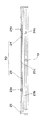
本発明の第1の実施形態にかかるディスク装置を、図面を参照しつつ説明する。まず、本発明の第1の実施形態にかかるディスク装置の基本構成を、図1を参照して説明する。図1は本発明の第1の実施形態にかかるディスク装置の分解斜視図である。
<< First Embodiment >>
A disk device according to a first embodiment of the present invention will be described with reference to the drawings. First, the basic configuration of the disk device according to the first embodiment of the present invention will be described with reference to FIG. FIG. 1 is an exploded perspective view of a disk device according to a first embodiment of the present invention.

本発明の第1の実施形態のディスク装置は、支持基板1と、支持基板1の上部を覆うように設けられた蓋体2とで形成される筐体60内に、図1に示す各部品及び装置等が取り付けられることによって構成されている。すなわち、支持基板1は、図1に示す各部品を支持している。支持基板1と蓋体2とで構成される筐体60の一側面には、ディスクを挿入及び排出するためのディスク挿入口44が形成されている。   The disk device according to the first embodiment of the present invention includes components shown in FIG. 1 in a housing 60 formed by a support substrate 1 and a lid body 2 provided to cover the upper portion of the support substrate 1. And a device or the like is attached. That is, the support substrate 1 supports each component shown in FIG. A disc insertion port 44 for inserting and ejecting a disc is formed on one side surface of the housing 60 constituted by the support substrate 1 and the lid 2.

支持基板1には、CDやDVD等のディスク状の記録媒体(以下、ディスクという)を装置内で回転させるターンテーブル3と、ディスクにデータの記録や再生を行う光ピックアップ4等が取り付けられている。ターンテーブル3と光ピックアップ4とは記録再生装置の一部を構成している。ここで、ターンテーブル3は、図8A〜図8Cを用いて、後で詳細に説明するように、スピンドルモータ3Aを構成するロータにより構成されている。支持基板1の、ディスク挿入方向42の下流側の一端部には、ディスクを装置内にローディングする際の回転力を発生させるモータ5が取り付けられている。モータ5の回転軸には第1プーリ6が圧入されている。第1プーリ6と同じ支持基板1の一側面側で且つディスク挿入方向42の上流側には、ウォームギヤ11と一体に形成された第2プーリ8が取り付けられている。第1プーリ6と第2プーリ8には、モータ5の回転軸の回転力を第1プーリ6から第2プーリ8に伝達するためにベルト7がかけられている。第2プーリ8は、第1プーリ6及びベルト7を介して伝達されたモータ5の回転軸の回転力により、ディスク挿入方向42に延在するギヤ軸10の一端に圧入されたはす歯ギヤ9を回転させて、ギヤ軸10の他端に圧入されたウォームギヤ11を回転させる。ここで、ウォームギヤ11は、はす歯ギヤ12とかみ合っており、はす歯ギヤ12は、リレーギヤ13及び14とかみ合っている。また、リレーギヤ13は、支持基板1に平行で且つディスク挿入方向42と交差する方向に延在するローラ軸18の一端部に圧入されたローラギヤ16とかみ合っており、リレーギヤ14は、ディスク挿入方向42に延在するカムロッド17をディスク挿入方向42又ディスク排出方向43に移動させる駆動ギヤ15とかみ合っている。したがって、ウォームギヤ11の回転力は、はす歯ギヤ12、リレーギヤ13及びローラギヤ16を介してローラ軸18に伝達される一方、はす歯ギヤ12、リレーギヤ14及び駆動ギヤ15を介してカムロッド17に伝達される。前記各ギヤにより、モータ5の回転軸の回転力は減速されて、駆動ギヤ15、ローラギヤ16の回転トルクが増加する。   Mounted on the support substrate 1 are a turntable 3 for rotating a disk-shaped recording medium (hereinafter referred to as a disk) such as a CD or DVD in the apparatus, an optical pickup 4 for recording or reproducing data on the disk, and the like. Yes. The turntable 3 and the optical pickup 4 constitute a part of the recording / reproducing apparatus. Here, the turntable 3 is constituted by a rotor constituting the spindle motor 3A, as will be described in detail later with reference to FIGS. 8A to 8C. A motor 5 is attached to one end of the support substrate 1 on the downstream side in the disc insertion direction 42 to generate a rotational force when loading the disc into the apparatus. A first pulley 6 is press-fitted into the rotating shaft of the motor 5. A second pulley 8 formed integrally with the worm gear 11 is attached to one side of the same support substrate 1 as the first pulley 6 and upstream of the disc insertion direction 42. A belt 7 is applied to the first pulley 6 and the second pulley 8 in order to transmit the rotational force of the rotating shaft of the motor 5 from the first pulley 6 to the second pulley 8. The second pulley 8 is a helical gear press-fitted into one end of the gear shaft 10 extending in the disk insertion direction 42 by the rotational force of the rotating shaft of the motor 5 transmitted through the first pulley 6 and the belt 7. 9 is rotated to rotate the worm gear 11 press-fitted into the other end of the gear shaft 10. Here, the worm gear 11 is engaged with the helical gear 12, and the helical gear 12 is engaged with the relay gears 13 and 14. The relay gear 13 meshes with the roller gear 16 that is press-fitted into one end of a roller shaft 18 that extends in a direction that is parallel to the support substrate 1 and intersects the disk insertion direction 42, and the relay gear 14 is in the disk insertion direction 42. Is engaged with the drive gear 15 that moves the cam rod 17 extending in the disc insertion direction 42 or the disc ejection direction 43. Accordingly, the rotational force of the worm gear 11 is transmitted to the roller shaft 18 via the helical gear 12, the relay gear 13 and the roller gear 16, while being applied to the cam rod 17 via the helical gear 12, the relay gear 14 and the drive gear 15. Communicated. By the gears, the rotational force of the rotating shaft of the motor 5 is reduced, and the rotational torque of the drive gear 15 and the roller gear 16 is increased.

ローラ軸18は、中空のゴムローラ19と係合しており、ローラギヤ16の回転力を摩擦力によって、ディスクを搬送するゴムローラ19に伝達している。ゴムローラ1は軸方向の中央側の径が小さく、端部に向かうに従い径が太くなるように形成されている。ローラ軸18は、その両端部において、支持基板1に平行で且つディスク挿入方向42と交差する方向に延在するシャフトホルダ20に回転可能に保持されている。シャフトホルダ20は、支持基板1に平行で且つディスク挿入方向42と交差する方向に延在するローラレバー21の上面に固定されている。ローラレバー21は、その両端部に設けられた軸受孔21a,21bに、支持基板1に設けられた一対の回動軸(図示しない)がそれぞれ嵌合することにより、支持基板1に回動自在に保持されており、一端がローラレバー21に取り付けられ、他端が支持基板1に取り付けられたつるまき状のバネ22の付勢力を受けて、シャフトホルダ20を介してゴムローラ19を上方向(蓋体2側)に押し上げるように構成されている。   The roller shaft 18 is engaged with a hollow rubber roller 19 and transmits the rotational force of the roller gear 16 to the rubber roller 19 that conveys the disk by frictional force. The rubber roller 1 has a small diameter on the central side in the axial direction, and is formed so that the diameter increases toward the end. The roller shaft 18 is rotatably supported at both ends thereof by a shaft holder 20 extending in a direction parallel to the support substrate 1 and intersecting the disc insertion direction 42. The shaft holder 20 is fixed to the upper surface of the roller lever 21 extending in a direction parallel to the support substrate 1 and intersecting the disc insertion direction 42. The roller lever 21 is rotatable on the support substrate 1 by fitting a pair of rotation shafts (not shown) provided on the support substrate 1 into bearing holes 21a and 21b provided at both ends thereof. The rubber roller 19 is moved upward (through the shaft holder 20) by receiving the urging force of a helical spring 22 having one end attached to the roller lever 21 and the other end attached to the support substrate 1. It is configured to push up toward the lid 2 side.

ローラ軸18のローラギヤ16側の先端部は、ローラギヤ16を突き抜けて、カムロッド17に形成されたカム溝17aと係合している。カム溝17aは、ディスク挿入方向42の下流側に向かうに従い、下方向(支持基板1側)に傾斜する傾斜部を備えている。モータ5が回転軸に回転力を発生させると、前記各ギヤに回転力が伝達され、ローラ軸18が回転するとともに、カムロッド17がディスク挿入方向42又はディスク排出方向43に移動する。このとき、ローラ軸18のローラギヤ16側の先端部がカム溝17aに沿って下方向又は上方向に移動するため、ローラ軸18と一体的に係合しているゴムローラ19も下方向又は上方向に移動する。また、ゴムローラ19を保持するシャフトホルダ20と、シャフトホルダ20を固定しているローラレバー21とは、ローラレバー21の軸受孔21a,21bが前記回動軸(図示しない)と嵌合している部分を中心に回動する。   The tip of the roller shaft 18 on the roller gear 16 side penetrates the roller gear 16 and engages with a cam groove 17 a formed in the cam rod 17. The cam groove 17a is provided with an inclined portion that is inclined downward (supporting substrate 1 side) toward the downstream side in the disk insertion direction 42. When the motor 5 generates a rotational force on the rotational shaft, the rotational force is transmitted to each gear, the roller shaft 18 rotates, and the cam rod 17 moves in the disc insertion direction 42 or the disc ejection direction 43. At this time, since the tip of the roller shaft 18 on the roller gear 16 side moves downward or upward along the cam groove 17a, the rubber roller 19 integrally engaged with the roller shaft 18 also moves downward or upward. Move to. In addition, the shaft holder 20 that holds the rubber roller 19 and the roller lever 21 that fixes the shaft holder 20 have the bearing holes 21a and 21b of the roller lever 21 fitted to the rotating shaft (not shown). Rotate around the part.

ゴムローラ19の上方には、バネ22により上方向に付勢されるゴムローラ19と協働してディスクを狭持し、ディスクをディスク挿入方向42に案内するディスクガイド50が支持基板1に平行で且つディスク挿入方向42と交差する方向に延在するクランプレバー25に取り付けられている。クランプレバー25は、ディスクガイド固定部の機能を果たしている。ディスクガイド50は、左ディスクガイド23と右ディスクガイド24とで構成されており、ディスクを傷つけないように、ディスクよりも柔らかい材料で形成されている。例えば、ディスクの材料がポリカーボネートであれば、それよりも柔らかいポリアセタール等の樹脂で形成されている。ディスクガイド50の構成については、後で詳しく説明する。   Above the rubber roller 19, in cooperation with the rubber roller 19 urged upward by the spring 22, a disk guide 50 for holding the disk and guiding the disk in the disk insertion direction 42 is parallel to the support substrate 1 and It is attached to a clamp lever 25 extending in a direction crossing the disc insertion direction 42. The clamp lever 25 functions as a disk guide fixing portion. The disc guide 50 includes a left disc guide 23 and a right disc guide 24, and is formed of a material softer than the disc so as not to damage the disc. For example, if the material of the disk is polycarbonate, it is formed of a softer resin such as polyacetal. The configuration of the disc guide 50 will be described in detail later.

クランプレバー25は、その両端部に形成された軸受孔25a,25bに、ローラレバー21と同様に前記回動軸(図示しない)が嵌合することにより、支持基板1に回動自在に支持されている。このクランプレバー25は、一方の端部に形成されたピン25cが、カムロッド17の、カム溝17aよりもディスク挿入方向42の下流側に形成されたカム溝17cに係合することによって、その姿勢がコントロールされている。カム溝17cは、ディスク挿入方向42の下流側に向かうに従い、下方向に傾斜する傾斜部を備えている。クランプレバー25の上面中央部には、ディスク挿入方向42の下流側に突出するように、弾性的な板バネで形成されたクランププレート26の一端部がネジ止めされている。クランププレート26の他端部は、その下面で円盤状のクランパ27を回動自在に支持している。クランプレバー25とクランププレート26とはクランプユニットの一例を構成している。モータ5の回転軸の回転力により、カムロッド17がディスク挿入方向42又はディスク排出方向43に移動すると、カムロッド17とカム溝17cで係合するクランプレバー25と、クランプレバー25に取り付けられたクランププレート26とは、クランプレバー25の軸受孔25a、25bが前記回動軸(図示しない)と嵌合している部分を中心に回動する。このとき、クランパ27は、下方向又は上方向に移動する。   The clamp lever 25 is rotatably supported by the support substrate 1 by fitting the rotation shaft (not shown) into the bearing holes 25a and 25b formed at both ends of the clamp lever 25 in the same manner as the roller lever 21. ing. The clamp lever 25 has a pin 25c formed at one end thereof engaged with a cam groove 17c formed downstream of the cam groove 17 in the disc insertion direction 42 with respect to the cam groove 17a. Is being controlled. The cam groove 17 c includes an inclined portion that is inclined downward as it goes downstream in the disc insertion direction 42. One end of a clamp plate 26 formed of an elastic leaf spring is screwed to the center of the upper surface of the clamp lever 25 so as to protrude downstream in the disc insertion direction 42. The other end of the clamp plate 26 rotatably supports a disc-shaped clamper 27 on its lower surface. The clamp lever 25 and the clamp plate 26 constitute an example of a clamp unit. When the cam rod 17 moves in the disc insertion direction 42 or the disc ejection direction 43 by the rotational force of the rotating shaft of the motor 5, the clamp lever 25 engaged with the cam rod 17 and the cam groove 17c, and the clamp plate attached to the clamp lever 25 26, the bearing holes 25a and 25b of the clamp lever 25 rotate around a portion where the rotation shaft (not shown) is fitted. At this time, the clamper 27 moves downward or upward.

蓋体2のディスク挿入口44近傍の下面には、ディスクを装置内に案内するガイド28が取り付けられている。また、蓋体2には、ガイド28にディスク挿入方向42の下流側で隣接するL字型の板材であるP板29が固定されている。P板29には2つの発光ダイオードが半田付けされている。蓋体2のディスク挿入方向42の下流側の下面には、規格直径8cmのディスク(以下、小径ディスクという)をターンテーブル3に位置決めするための、左センタリングレバー30と右センタリングレバー31とが設けられている。左センタリングレバー30と右センタリングレバー31とは、それぞれに設けられた軸受孔30a,31aに、蓋体2に設けられた一対の回動軸(図示しない)が嵌合することで、回動自在に取り付けられている。また、左センタリングレバー30と右センタリングレバー31とは、左センタリングレバー30の一端部に設けられた係合孔30cに、右センタリングレバーの一端部に形成された係合ピン(図示しない)が係合することにより、移動可能に係合している。   A guide 28 for guiding the disk into the apparatus is attached to the lower surface of the lid 2 near the disk insertion port 44. Further, a P plate 29, which is an L-shaped plate material adjacent to the guide 28 on the downstream side in the disc insertion direction 42, is fixed to the lid 2. Two light emitting diodes are soldered to the P plate 29. A left centering lever 30 and a right centering lever 31 for positioning a disk having a standard diameter of 8 cm (hereinafter referred to as a small diameter disk) on the turntable 3 are provided on the lower surface of the lid 2 on the downstream side in the disk insertion direction 42. It has been. The left centering lever 30 and the right centering lever 31 are rotatable by fitting a pair of rotation shafts (not shown) provided in the lid body 2 into bearing holes 30a and 31a provided in the respective centers. Is attached. Further, the left centering lever 30 and the right centering lever 31 are engaged with an engagement pin (not shown) formed at one end of the right centering lever in an engagement hole 30c provided at one end of the left centering lever 30. By engaging, they are movably engaged.

左センタリングレバー30には、付勢バネ32が取り付けられており、軸受穴30aを中心に反時計方向に付勢されている。この付勢バネ32により、係合孔30cで左センタリングレバー30と移動可能に係合している右センタリングレバー31は、軸受穴31a中心に時計方向に力を受けている。つまり、左センタリングレバー30の他端部に設けられた位置決めピン30bと右センタリングレバー31の他端部に設けられた位置決めピン31bとが、付勢バネ32によって互いにターンテーブル3に近づく方向に付勢されている。   A biasing spring 32 is attached to the left centering lever 30 and is biased counterclockwise about the bearing hole 30a. By the biasing spring 32, the right centering lever 31 movably engaged with the left centering lever 30 through the engagement hole 30c receives a force in the clockwise direction around the bearing hole 31a. That is, the positioning pin 30b provided at the other end of the left centering lever 30 and the positioning pin 31b provided at the other end of the right centering lever 31 are attached to the turntable 3 in a direction approaching each other by the biasing spring 32. It is energized.

右センタリングレバー31の上面には、ロックレバー33が回動自在に設けられている。ロックレバー33のディスク挿入方向42の下流側の端部には係合ピン33bが設けられている。係合ピン33bは蓋体2に形成されたロック部2aに係合することで、右センタリングレバー31が軸受穴31aを中心として反時計方向(外側に開く方向)へ移動するのを規制するとともに、係合孔30cで右センタリングレバー31の一端部に形成されたピン(図示しない)と係合している左センタリングレバー30が軸受穴30aを中心として時計方向へ移動するのを規制している。つまり、左センタリングレバー30と右センタリングレバー31とは、係合ピン33bがロック部2aに係合することにより、外側に開く方向へ移動するのを規制されている。ロックレバー33のディスク挿入方向42の上流側の端部には当接ピン33aが設けられている。当接ピン33aは、ディスクと当接してディスク挿入方向42に押されることにより、ロックレバー33の本体を反時計方向に回転させて、係合ピン33bとロック部2aとの係合を外すことができるように設けられている。また、ロックレバー33は、右センタリングレバー31に設けられたバネ34により係合ピン33bがロック部2aと係合する方向(時計方向)に付勢されている。したがって、ロックレバー33は、通常、係合ピン33bがロック部2aと係合してロック状態にある。また、ロックレバー33と接続されている右センタリングレバー31と、右センタリングレバー31と接続されている左センタリングレバー30もロック状態にある。   A lock lever 33 is rotatably provided on the upper surface of the right centering lever 31. An engagement pin 33 b is provided at the downstream end of the lock lever 33 in the disk insertion direction 42. The engaging pin 33b engages with the lock portion 2a formed on the lid body 2 to restrict the right centering lever 31 from moving counterclockwise (opening outward) around the bearing hole 31a. The left centering lever 30 engaged with a pin (not shown) formed at one end of the right centering lever 31 through the engagement hole 30c is restricted from moving clockwise around the bearing hole 30a. . That is, the left centering lever 30 and the right centering lever 31 are restricted from moving outwardly when the engagement pin 33b engages with the lock portion 2a. A contact pin 33 a is provided at the upstream end of the lock lever 33 in the disk insertion direction 42. The abutment pin 33a abuts against the disc and is pushed in the disc insertion direction 42, thereby rotating the main body of the lock lever 33 counterclockwise to disengage the engagement pin 33b from the lock portion 2a. It is provided so that you can. The lock lever 33 is urged in a direction (clockwise) in which the engagement pin 33b engages with the lock portion 2a by a spring 34 provided on the right centering lever 31. Therefore, the lock lever 33 is normally in a locked state with the engagement pin 33b engaged with the lock portion 2a. The right centering lever 31 connected to the lock lever 33 and the left centering lever 30 connected to the right centering lever 31 are also in a locked state.

右センタリングレバー31の下面には、ディスクに当接してカムロッド17にトリガーをかけるトリガーレバー35が回動自在に設けられている。トリガーレバー35の装置中央側の端部にはディスクと当接するための当接ピン35aが設けられており、反対側の端部にはトリガーロッド36に設けられたカム溝36aと係合する駆動ピン35bが設けられている。また、トリガーロッド35はバネ34によりロックレバー33と逆方向、つまり反時計方向に付勢されている。   On the lower surface of the right centering lever 31, a trigger lever 35 that contacts the disc and triggers the cam rod 17 is rotatably provided. A contact pin 35a for contacting the disk is provided at the end of the trigger lever 35 on the center side of the apparatus, and a drive engaged with a cam groove 36a provided in the trigger rod 36 is provided at the end on the opposite side. A pin 35b is provided. The trigger rod 35 is biased by the spring 34 in the opposite direction to the lock lever 33, that is, counterclockwise.

トリガーロッド36は支持基板1に摺動自在にガイドされて取り付けられており、トリガーレバー35の回動動作により、ディスク挿入方向42又はディスク排出方向43に移動した後、ディスク挿入方向42と交差する方向に移動可能に設けられている。また、トリガーロッド36は、通常、ディスク挿入方向42の下流側で待機するように、バネ22によって付勢されている。トリガーロッド36は、ディスク排出方向43に移動すると、カムロッド17と当接して、カムロッド17をディスク挿入方向42に押すように設けられている。また、トリガーロッド36は、ディスク挿入方向42と交差方向に移動をしたとき、カム溝36aで駆動ピン35bをガイドして、トリガーレバー35を時計方向に回転させるように設けられている。トリガーロッド36に押されてディスク挿入方向42に移動するカムロッド17は、その動作の途中でカムロッド17に設けられたラック17cと駆動ギヤ15とをかみ合わせるように設けられている。また、カムロッド17にはトリガーロッド36をディスク挿入方向42と交差方向に移動させるカム溝17dが設けられている。   The trigger rod 36 is slidably guided and attached to the support substrate 1. The trigger rod 36 moves in the disc insertion direction 42 or the disc ejection direction 43 by the rotation of the trigger lever 35, and then intersects the disc insertion direction 42. It is provided to be movable in the direction. The trigger rod 36 is normally biased by the spring 22 so as to stand by on the downstream side in the disc insertion direction 42. When the trigger rod 36 moves in the disc ejection direction 43, the trigger rod 36 abuts on the cam rod 17 and pushes the cam rod 17 in the disc insertion direction 42. The trigger rod 36 is provided so as to guide the drive pin 35b with the cam groove 36a and rotate the trigger lever 35 in the clockwise direction when moving in the direction intersecting the disc insertion direction 42. The cam rod 17 that is pushed by the trigger rod 36 and moves in the disc insertion direction 42 is provided so as to mesh the rack 17c provided on the cam rod 17 and the drive gear 15 during the operation. The cam rod 17 is provided with a cam groove 17d for moving the trigger rod 36 in the direction intersecting the disc insertion direction 42.

支持基板1には、カムロッド17の移動の終端を検出するスイッチ38が設けられたメカP板39が固定されている。メカP板39には、P板29に設けられた発光ダイオードの光を検出する受光素子40,41が設けられている。受光素子40は、ゴムローラ19の中央部の、ディスク挿入方向42の上流側近傍に設けられ、ディスクが挿入されてディスクにより光が遮断されたことを検出する。受光素子41は、ゴムローラ19の中央部の、ディスク挿入方向42の下流側右寄り近傍に設けられ、ディスクが排出されてディスクにより遮断されていた光が受光されたことを検出する。   A mechanical P plate 39 provided with a switch 38 for detecting the end of movement of the cam rod 17 is fixed to the support substrate 1. The mechanical P plate 39 is provided with light receiving elements 40 and 41 for detecting light from the light emitting diodes provided on the P plate 29. The light receiving element 40 is provided near the upstream side in the disc insertion direction 42 at the center of the rubber roller 19 and detects that the disc has been inserted and the light has been blocked by the disc. The light receiving element 41 is provided near the right side of the downstream side in the disc insertion direction 42 at the center of the rubber roller 19 and detects that the light that has been ejected and blocked by the disc has been received.

本発明の第1の実施形態のディスク装置は、以上のように構成されている。
なお、第1の実施形態のディスク装置においては、モータ5、第1プーリ6、ベルト7、第2プーリ8、はす歯ギヤ9、ギヤ軸10、ウォームギヤ11、はす歯ギヤ12、リレーギヤ13、ローラギヤ16、カムロッド17、ローラ軸18、ゴムローラ19、シャフトホルダ20、及びローラレバー21により、ディスク搬送装置の一例を構成している。
また、第1の実施形態のディスク装置においては、モータ5、第1プーリ6、ベルト7、第2プーリ8、はす歯ギヤ9、ギヤ軸10、ウォームギヤ11、はす歯ギヤ12、リレーギヤ13、リレーギヤ14、駆動ギヤ15、カムロッド17、クランプレバー25、クランププレート26、及びクランパ27により、ディスククランプ装置の一例を構成している。
また。第1の実施形態のディスク装置においては、モータ5、第1プーリ6、ベルト7、第2プーリ8、はす歯ギヤ9、ギヤ軸10、ウォームギヤ11、はす歯ギヤ12、リレーギヤ13、リレーギヤ14、駆動ギヤ15、カムロッド17により駆動機構の一例が形成されている。
The disk device according to the first embodiment of the present invention is configured as described above.
In the disk device of the first embodiment, the motor 5, the first pulley 6, the belt 7, the second pulley 8, the helical gear 9, the gear shaft 10, the worm gear 11, the helical gear 12, and the relay gear 13 are used. The roller gear 16, the cam rod 17, the roller shaft 18, the rubber roller 19, the shaft holder 20, and the roller lever 21 constitute an example of a disk transport device.
In the disk device of the first embodiment, the motor 5, the first pulley 6, the belt 7, the second pulley 8, the helical gear 9, the gear shaft 10, the worm gear 11, the helical gear 12, and the relay gear 13 are used. The relay gear 14, the drive gear 15, the cam rod 17, the clamp lever 25, the clamp plate 26, and the clamper 27 constitute an example of a disk clamp device.
Also. In the disk device of the first embodiment, the motor 5, the first pulley 6, the belt 7, the second pulley 8, the helical gear 9, the gear shaft 10, the worm gear 11, the helical gear 12, the relay gear 13, and the relay gear. 14, the drive gear 15, and the cam rod 17 form an example of a drive mechanism.

次に、本発明の第1の実施形態にかかるディスク装置の動作について図1を参照しつつ説明する。
まず、小径ディスクのローディング動作について説明する。
Next, the operation of the disk device according to the first embodiment of the present invention will be described with reference to FIG.
First, the loading operation of a small diameter disk will be described.

使用者により小径ディスクがディスク挿入方向42から挿入されると、小径ディスクは、ガイド28にガイドされて装置内に導かれ、まず、P板29に取り付けられた発光ダイオードの光を受光素子40に対して遮断する。受光素子40が、発光ダイオードの光が遮断されたことを検出すると、モータ5が回転軸に回転力を発生させる。モータ5の回転軸の回転力は、第1プーリ6、ベルト7、第2プーリ8、はす歯ギヤ9、ギヤ軸10、ウォームギヤ11、はす歯ギヤ12、及びリレーギヤ13を介して減速された後、ローラギヤ16に伝達される。このとき、はす歯ギヤ12からリレーギヤ14を介して駆動ギヤ15が回転させられるが、カムロッド17のラック17cとは、まだかみ合っておらず、駆動ギヤ15は空転する。モータ5の回転軸の回転力が伝達されてローラギヤ16が回転すると、それに伴い、ローラ軸18が回転し、ローラ軸18に係合しているゴムローラ19も摩擦力により、一緒に回転を開始する。このとき、ローラ軸18は、一対のバネ22により、ローラレバー21とシャフトホルダ20とを介して上方向に付勢されて、カムロッド17のカム溝17aの上方で待機している。また、このとき、ゴムローラ19は、ディスクガイド50との間に隙間を持っているため、ローラ軸18の回転により空転している。   When the user inserts the small-diameter disk from the disk insertion direction 42, the small-diameter disk is guided by the guide 28 and guided into the apparatus. First, light from the light-emitting diode attached to the P plate 29 is transmitted to the light receiving element 40. Block against this. When the light receiving element 40 detects that the light from the light emitting diode is blocked, the motor 5 generates a rotational force on the rotating shaft. The rotational force of the rotating shaft of the motor 5 is decelerated via the first pulley 6, the belt 7, the second pulley 8, the helical gear 9, the gear shaft 10, the worm gear 11, the helical gear 12, and the relay gear 13. Then, it is transmitted to the roller gear 16. At this time, the drive gear 15 is rotated from the helical gear 12 via the relay gear 14, but it is not yet engaged with the rack 17 c of the cam rod 17, and the drive gear 15 rotates idly. When the rotational force of the rotating shaft of the motor 5 is transmitted and the roller gear 16 rotates, the roller shaft 18 rotates accordingly, and the rubber roller 19 engaged with the roller shaft 18 also starts to rotate together by the frictional force. . At this time, the roller shaft 18 is biased upward by the pair of springs 22 via the roller lever 21 and the shaft holder 20, and stands by above the cam groove 17 a of the cam rod 17. At this time, since the rubber roller 19 has a gap between it and the disk guide 50, the rubber roller 19 is idled by the rotation of the roller shaft 18.

さらに、使用者が小径ディスクをディスク挿入方向42に挿入していくと、小径ディスクはゴムローラ19と当接して、ゴムローラ19とディスクガイド50との間に挟まれる。このとき、小径ディスクは、ゴムローラ19を介してバネ22の上方向の付勢力を受けて、ディスクガイド50に押し付けられる。このとき、ローラ軸18と小径ディスクとの間に挟まれるゴムローラ19は、ローラ軸18との摩擦力が上がり、大きな回転力を持つようになる。ゴムローラ19とディスクガイド50に挟まれた小径ディスクは、このゴムローラ19の回転力を受けてディスク挿入方向42に搬送される。   Further, when the user inserts the small-diameter disk in the disk insertion direction 42, the small-diameter disk contacts the rubber roller 19 and is sandwiched between the rubber roller 19 and the disk guide 50. At this time, the small diameter disk receives an upward biasing force of the spring 22 via the rubber roller 19 and is pressed against the disk guide 50. At this time, the rubber roller 19 sandwiched between the roller shaft 18 and the small-diameter disk increases the frictional force with the roller shaft 18 and has a large rotational force. The small-diameter disk sandwiched between the rubber roller 19 and the disk guide 50 receives the rotational force of the rubber roller 19 and is conveyed in the disk insertion direction 42.

さらに、モータ5の回転軸の回転力により小径ディスクが搬送されると、小径ディスクはディスクガイド50にガイドされて、ターンテーブル3とクランパ27の隙間を通過し、トリガーレバー35の当接ピン35aと当接し、続いて左センタリングレバー30の位置決めピン30bと、右センタリングレバー31の位置決めピン31bとに当接する。このとき、右センタリングレバー31に設けられたロックレバー33の当接ピン33aは、小径ディスクと当接していないため、蓋体2のロック部2aと係合しており、右センタリングレバー31と左センタリングレバー30とは移動を規制されている。つまり、右センタリングレバー31は反時計方向の回転を規制され、左センタリングレバー30は時計方向の回転を規制されている。したがって、小径ディスクは、回転を規制されている右センタリングレバーの位置決めピン30b及び左センタリングレバー30の位置決めピン31bと当接することにより、ディスク挿入方向42の移動を規制され、ディスク記録再生位置に対向する(近傍で且つ同軸(例えば図1の上方)に離れた)ディスク装着準備位置に位置決めされる。ここで、ディスク記録再生位置とは、ディスクがターンテーブル3に装着されて、再生又は、再生及び記録可能な位置をいう。   Further, when the small-diameter disk is conveyed by the rotational force of the rotating shaft of the motor 5, the small-diameter disk is guided by the disk guide 50, passes through the gap between the turntable 3 and the clamper 27, and contacts the pin 35a of the trigger lever 35. And then contact the positioning pin 30b of the left centering lever 30 and the positioning pin 31b of the right centering lever 31. At this time, the contact pin 33a of the lock lever 33 provided on the right centering lever 31 is not in contact with the small-diameter disk, and therefore is engaged with the lock portion 2a of the lid 2 so that the right centering lever 31 and the left Movement with respect to the centering lever 30 is restricted. That is, the right centering lever 31 is restricted from rotating counterclockwise, and the left centering lever 30 is restricted from rotating clockwise. Therefore, the small-diameter disc is restricted from moving in the disc insertion direction 42 by contacting the positioning pin 30b of the right centering lever and the positioning pin 31b of the left centering lever 30 whose rotation is restricted, and is opposed to the disc recording / reproducing position. Is positioned at a disk mounting preparation position (near and separated coaxially (eg, upward in FIG. 1)). Here, the disk recording / reproducing position means a position where the disk is mounted on the turntable 3 and can be reproduced or reproduced and recorded.

また、このとき、右センタリングレバー31に回動自在に設けられたトリガーレバー35は、当接ピン35aが小径ディスクに押されることで時計方向に回転し、駆動ピン35bがディスク排出方向43に移動する。駆動ピン35bはトリガーロッド36のカム溝36aと係合しているため、駆動ピン35bのディスク排出方向43の移動により、トリガーロッド36もディスク排出方向43に移動する。   At this time, the trigger lever 35 rotatably provided on the right centering lever 31 rotates clockwise when the contact pin 35 a is pushed by the small-diameter disk, and the drive pin 35 b moves in the disk ejection direction 43. To do. Since the drive pin 35 b is engaged with the cam groove 36 a of the trigger rod 36, the trigger rod 36 also moves in the disc discharge direction 43 when the drive pin 35 b moves in the disc discharge direction 43.

トリガーレバー35によりディスク排出方向43に移動するトリガーロッド36は、トリガーロッド36よりディスク挿入方向42の上流側に設けられているカムロッド17と当接して、カムロッド17をディスク排出方向43に押す。トリガーロッド36に押されたカムロッド17は、ラック17cにおいて駆動ギヤ15とかみ合い、モータ5の回転軸の回転力を受けて空転している駆動ギヤ15の回転力を受けて、さらにディスク挿入方向42に移動する。   The trigger rod 36 moved in the disc discharge direction 43 by the trigger lever 35 abuts on the cam rod 17 provided on the upstream side of the disc insertion direction 42 with respect to the trigger rod 36 and pushes the cam rod 17 in the disc discharge direction 43. The cam rod 17 pushed by the trigger rod 36 meshes with the drive gear 15 in the rack 17c, receives the rotational force of the rotating drive gear 15 due to the rotational force of the rotation shaft of the motor 5, and further receives the rotational force of the drive gear 15 and further receives the disc insertion direction 42. Move to.

カムロッド17には、ディスク挿入方向42の下流側に向かうに従い下方に傾斜する傾斜部を備え、ローラ軸18と係合するカム溝17aと、ディスク挿入方向42の下流側に向かうに従い下方に傾斜する傾斜部を備え、クランプレバー25に設けられたピン25cと係合するカム溝17bとが形成されている。カムロッド17のディスク排出方向43の移動に従い、ローラ軸19はカム溝17aにより下方向に押し下げられ、クランプレバー25のピン25cはカム溝17bにより下方向に押し下げられる。   The cam rod 17 is provided with an inclined portion that is inclined downward as it goes downstream in the disk insertion direction 42, and is inclined downward as it goes toward the downstream side of the disk insertion direction 42 and the cam groove 17 a that engages with the roller shaft 18. A cam groove 17b that includes an inclined portion and engages with a pin 25c provided on the clamp lever 25 is formed. As the cam rod 17 moves in the disc discharge direction 43, the roller shaft 19 is pushed downward by the cam groove 17a, and the pin 25c of the clamp lever 25 is pushed downward by the cam groove 17b.

ローラ軸18が押し下げられると、ローラ軸18に係合するゴムローラ19も押し下げられて、小径ディスクも一緒に下方向へ下がっていく。また、これと同時に、係合ピン25aが押し下げられると、クランプレバー25は、軸受孔21a,21bが支持基板1に設けられた前記一対の回動軸(図示しない)と嵌合している部分を中心に時計方向に回転して、クランププレート26を介してクランパ27を押し下げて、クランパ27をディスク装着準備位置に位置している小径ディスクに当接させる。この間にローラ軸18に圧入されたローラギヤ16も下がっていくため、リレーギヤ13とローラギヤ16とのかみ合いが外れてゴムローラ19の回転が停止する。   When the roller shaft 18 is pushed down, the rubber roller 19 engaged with the roller shaft 18 is also pushed down, and the small-diameter disk is also lowered downward. At the same time, when the engaging pin 25a is pushed down, the clamp lever 25 is a portion in which the bearing holes 21a and 21b are engaged with the pair of rotating shafts (not shown) provided in the support substrate 1. And the clamper 27 is pushed down via the clamp plate 26 to bring the clamper 27 into contact with the small-diameter disk positioned at the disk mounting preparation position. During this time, the roller gear 16 press-fitted into the roller shaft 18 is also lowered, so that the meshing between the relay gear 13 and the roller gear 16 is released and the rotation of the rubber roller 19 is stopped.

トリガーレバー35がトリガーロッド36を移動させてからローラギヤ16が停止するまでの間、小径ディスクは移動を停止しているが、ゴムローラ19とローラ軸18とは摩擦力で駆動力を伝達しているのでスリップすることが可能であるため、ローラ軸18の回転は拘束されず、モータ5の回転軸の回転は停止することがない。このため、カムロッド17はモータ5の回転軸の回転力によりディスク排出方向43に移動をしつづける。   The small-diameter disk stops moving from when the trigger lever 35 moves the trigger rod 36 until the roller gear 16 stops, but the rubber roller 19 and the roller shaft 18 transmit driving force by frictional force. Therefore, since it is possible to slip, rotation of the roller shaft 18 is not restrained and rotation of the rotation shaft of the motor 5 does not stop. For this reason, the cam rod 17 continues to move in the disc ejection direction 43 by the rotational force of the rotating shaft of the motor 5.

さらに、カムロッド17のディスク排出方向43の移動が続くと、ゴムローラ19は完全に小径ディスクから離れて再生又は記録状態における所定の待機位置まで移動する。また、このとき同時に、クランプレバー25も時計方向の回転を続け、クランパ27を介して小径ディスクを押し下げて、小径ディスクをターンテーブル3に押し付ける。このとき、クランププレート26は弾性変形して、一定の圧力でクランパ27を介して小径ディスクをターンテーブル3に押し付ける。   Further, when the cam rod 17 continues to move in the disc discharge direction 43, the rubber roller 19 completely moves away from the small-diameter disc and moves to a predetermined standby position in the reproduction or recording state. At the same time, the clamp lever 25 continues to rotate in the clockwise direction, and the small-diameter disk is pushed down via the clamper 27 to press the small-diameter disk against the turntable 3. At this time, the clamp plate 26 is elastically deformed, and the small-diameter disk is pressed against the turntable 3 through the clamper 27 with a constant pressure.

さらに、カムロッド17がディスク排出方向43に移動すると、カム溝17dによって、トリガーロッド36が装置中央方向に移動する。トリガーロッド36が移動すると、カム溝36aによって、トリガーレバー35の駆動ピン35bがディスク排出方向43に押され、トリガーレバー35は、当接ピン35aを小径ディスクから離れる方向(時計方向)に回転する。これにより、小径ディスクのディスク記録再生位置への装着が完了する。一方、ディスク排出方向43に移動するカムロッド17は、最終的にスイッチ38と当接して、スイッチ38をONにする。スイッチ38のONにより、モータ5の回転軸が回転を停止して、ローディングが完了する。これにより、ターンテーブル3によって小径ディスクを回転させて、光ピックアップ4により小径ディスクの再生又は、再生及び録音することが可能となる。   Further, when the cam rod 17 moves in the disc discharge direction 43, the trigger rod 36 moves toward the center of the apparatus by the cam groove 17d. When the trigger rod 36 moves, the drive pin 35b of the trigger lever 35 is pushed in the disc discharge direction 43 by the cam groove 36a, and the trigger lever 35 rotates in the direction away from the small-diameter disc (clockwise). . Thereby, the mounting of the small-diameter disk to the disk recording / reproducing position is completed. On the other hand, the cam rod 17 moving in the disc ejection direction 43 finally comes into contact with the switch 38 and turns on the switch 38. When the switch 38 is turned on, the rotation shaft of the motor 5 stops rotating and loading is completed. As a result, the small-diameter disk can be rotated by the turntable 3 and the small-diameter disk can be reproduced or reproduced and recorded by the optical pickup 4.

次に、小径ディスクの排出動作について説明する。
小径ディスクの排出動作は、基本的にはローディング動作と逆の動作を行う。
Next, the discharge operation of the small diameter disc will be described.
The discharge operation of the small-diameter disk is basically the reverse of the loading operation.

装置に別途設けられたイジェクトボタンが押されるなどにより、小径ディスクの排出動作開始が指示されると、モータ5がローディング動作時とは逆方向に回転軸に回転力を発生させる。モータ5の回転軸の回転力は、各ギヤにより駆動ギヤ15に伝達されて、カムロッド17をディスク挿入方向42に移動させる。このカムロッド17の移動に伴い、ローラ軸18とクランプレバー25のピン25cとは、カム溝17a,17bにより上方向に移動する。この動作に伴い、クランプレバー25は、クランププレート26を介してクランパ27を上方向に持ち上げ、クランパ27を小径ディスクから離れさせる。これと同時に、ローラ軸18に係合するゴムローラ19は、上方向に移動して小径ディスクを持ち上げ、小径ディスクをディスクガイド50に押し付けて挟み込む。   When an instruction to start ejecting the small-diameter disk is issued, for example, by pressing an eject button provided separately in the apparatus, the motor 5 generates a rotational force on the rotating shaft in the direction opposite to that during the loading operation. The rotational force of the rotating shaft of the motor 5 is transmitted to the drive gear 15 by each gear, and moves the cam rod 17 in the disc insertion direction 42. As the cam rod 17 moves, the roller shaft 18 and the pin 25c of the clamp lever 25 move upward by the cam grooves 17a and 17b. Along with this operation, the clamp lever 25 lifts the clamper 27 upward via the clamp plate 26 and separates the clamper 27 from the small diameter disk. At the same time, the rubber roller 19 engaged with the roller shaft 18 moves upward to lift the small-diameter disk, and presses the small-diameter disk against the disk guide 50 so as to be sandwiched.

ローラ軸18の上方向の移動に伴い、ローラギヤ16とリレーギヤ13とのかみ合いも回復して、ローラギヤ16にモータ5の回転軸の回転力が伝達される。ローラギヤ16によりモータ5の回転軸の回転力を伝達されたゴムローラ19は、ローディング動作時とは逆方向に回転して、ディスクガイド50と協働して挟み込んでいる小径ディスクを、ディスク排出方向43に搬送する。このとき、クランパ27はディスク記録再生位置から完全に退避して、ターンテーブル3との間に隙間を形成して、小径ディスクの搬送動作を妨げない。また、ディスク挿入方向42に移動するカムロッド17は、最終的にラック17cとのかみ合いが外れ、トリガーロッド36に架けられたバネ37の付勢力を受けて、初期の位置に復帰する。   As the roller shaft 18 moves upward, the meshing between the roller gear 16 and the relay gear 13 is restored, and the rotational force of the rotating shaft of the motor 5 is transmitted to the roller gear 16. The rubber roller 19 to which the rotational force of the rotating shaft of the motor 5 is transmitted by the roller gear 16 rotates in the opposite direction to that during the loading operation, and the small-diameter disk sandwiched in cooperation with the disk guide 50 is inserted in the disk discharge direction 43. Transport to. At this time, the clamper 27 is completely retracted from the disk recording / reproducing position, and a gap is formed between the clamper 27 and the turntable 3 so as not to disturb the transport operation of the small-diameter disk. Further, the cam rod 17 moving in the disc insertion direction 42 is finally disengaged from the rack 17c, and is returned to the initial position under the biasing force of the spring 37 hung on the trigger rod 36.

さらに、ゴムローラ19が逆方向に回転して、小径ディスクをディスク排出方向43に移動させていくと、受光素子41が、小径ディスクにより遮断されていたP板29の発光ダイオードの光を受光する。これにより、モータ5は駆動動作を停止する。このとき、小径ディスクは、受光素子41がゴムローラ19よりディスク挿入方向42の下流側に配置されているため、ゴムローラ19に挟まれた状態で停止する。したがって、小径ディスクは装置から落ちない。   Further, when the rubber roller 19 rotates in the reverse direction to move the small diameter disk in the disk discharge direction 43, the light receiving element 41 receives the light of the light emitting diode of the P plate 29 that has been blocked by the small diameter disk. Thereby, the motor 5 stops the driving operation. At this time, since the light receiving element 41 is disposed downstream of the rubber roller 19 in the disk insertion direction 42, the small-diameter disk stops in a state of being sandwiched between the rubber rollers 19. Therefore, the small diameter disc does not fall out of the device.

次に、規格直径が12cmのディスク(以下、大径ディスクという)のローディング動作について説明する。
使用者により大径ディスクがディスク挿入方向42から挿入されると、大径ディスクは、ガイド28にガイドされて装置内に導かれ、まず、P板29に取り付けられた発光ダイオードの光を受光素子40に対して遮断する。受光素子40が、発光ダイオードの光が遮断されたことを検出すると、モータ5が回転軸に回転力を発生させる。モータ5の回転軸の回転力は、第1プーリ6、ベルト7、第2プーリ8、はす歯ギヤ9、ギヤ軸10、ウォームギヤ11、はす歯ギヤ12、リレーギヤ13を介して減速された後、ローラギヤ16に伝達される。このとき、はす歯ギヤ12からリレーギヤ14を介して駆動ギヤ15が回転させられるが、カムロッド17のラック17cとは、まだかみ合っておらず、駆動ギヤ15は空転する。モータ5の回転軸の回転力が伝達されてローラギヤ16が回転すると、それに伴い、ローラ軸18が回転し、ローラ軸18に係合しているゴムローラ19も摩擦力により、一緒に回転を開始する。このとき、ローラ軸18は、一対のバネ22により、ローラレバー21とシャフトホルダ20とを介して上方向に付勢されて、カムロッド17のカム溝17aの上方に待機している。また、このとき、ゴムローラ19は、ディスクガイド50との間に隙間を持っているため、ローラ軸18の回転により空転している。
Next, a loading operation of a disk having a standard diameter of 12 cm (hereinafter referred to as a large diameter disk) will be described.
When the user inserts a large-diameter disk from the disk insertion direction 42, the large-diameter disk is guided by the guide 28 and guided into the apparatus. Block against 40. When the light receiving element 40 detects that the light from the light emitting diode is blocked, the motor 5 generates a rotational force on the rotating shaft. The rotational force of the rotating shaft of the motor 5 was decelerated through the first pulley 6, the belt 7, the second pulley 8, the helical gear 9, the gear shaft 10, the worm gear 11, the helical gear 12, and the relay gear 13. Then, it is transmitted to the roller gear 16. At this time, the drive gear 15 is rotated from the helical gear 12 via the relay gear 14, but it is not yet engaged with the rack 17 c of the cam rod 17, and the drive gear 15 rotates idly. When the rotational force of the rotating shaft of the motor 5 is transmitted and the roller gear 16 rotates, the roller shaft 18 rotates accordingly, and the rubber roller 19 engaged with the roller shaft 18 also starts to rotate together by the frictional force. . At this time, the roller shaft 18 is biased upward by the pair of springs 22 via the roller lever 21 and the shaft holder 20, and stands by above the cam groove 17 a of the cam rod 17. At this time, since the rubber roller 19 has a gap between it and the disk guide 50, the rubber roller 19 is idled by the rotation of the roller shaft 18.

さらに、使用者が大径ディスクをディスク挿入方向42に挿入していくと、大径ディスクはゴムローラ19と当接して、ゴムローラ19とディスクガイド50との間に挟まれる。このとき、大径ディスクは、ゴムローラ19を介してバネ22の上方向の付勢力を受けて、ディスクガイド50に押し付けられる。このとき、ローラ軸18と大径ディスクとの間に挟まれるゴムローラ19は、ローラ軸18との摩擦力が上がり、大きな回転力を持つようになる。ゴムローラ19とディスクガイド50に挟まれた大径ディスクは、このゴムローラ19の回転力を受けてディスク挿入方向42に搬送される。   Further, when the user inserts a large-diameter disk in the disk insertion direction 42, the large-diameter disk contacts the rubber roller 19 and is sandwiched between the rubber roller 19 and the disk guide 50. At this time, the large diameter disk receives an upward biasing force of the spring 22 via the rubber roller 19 and is pressed against the disk guide 50. At this time, the rubber roller 19 sandwiched between the roller shaft 18 and the large-diameter disk increases the frictional force with the roller shaft 18 and has a large rotational force. The large-diameter disk sandwiched between the rubber roller 19 and the disk guide 50 receives the rotational force of the rubber roller 19 and is conveyed in the disk insertion direction 42.

さらに、モータ5の回転軸の回転力により大径ディスクが搬送されると、大径ディスクはディスクガイド50にガイドされて、ターンテーブル3とクランパ27の隙間を通過し、ロックレバー33の当接ピン33aに当接して、当接ピン33aを押す。当接ピン33aを押されたロックレバー33は、反時計方向に回転する。この回転により、当接ピン33aと反対側の端部に設けられた係合ピン33bが蓋体2のロック部2aより外れて、各レバーのロックが解除される。   Further, when the large-diameter disk is conveyed by the rotational force of the rotating shaft of the motor 5, the large-diameter disk is guided by the disk guide 50, passes through the gap between the turntable 3 and the clamper 27, and comes into contact with the lock lever 33. Abutting on the pin 33a, the abutting pin 33a is pushed. When the contact pin 33a is pushed, the lock lever 33 rotates counterclockwise. By this rotation, the engagement pin 33b provided at the end opposite to the contact pin 33a is disengaged from the lock portion 2a of the lid 2, and the lock of each lever is released.

さらに、モータ5の回転軸の回転力により大径ディスクが搬送されると、大径ディスクは、トリガーレバー35の当接ピン35aに当接し、続いて左センタリングレバー30の当接ピン30aと、右センタリングレバー31の当接ピン31aとに当接する。このとき、ロックレバー33のロックは解除された状態になっているため、トリガーレバー35、左センタリングレバー30及び右センタリングレバー31は移動を規制されること無く、大径ディスクの外周部に押されて外側に開いていく。つまり、トリガーレバー35は時計方向に回転し、左センタリングレバー30は時計方向に回転し、右センタリングレバー31は反時計方向に回転する。   Further, when the large-diameter disk is conveyed by the rotational force of the rotating shaft of the motor 5, the large-diameter disk contacts the contact pin 35a of the trigger lever 35, and then the contact pin 30a of the left centering lever 30; It contacts the contact pin 31a of the right centering lever 31. At this time, since the lock of the lock lever 33 is released, the trigger lever 35, the left centering lever 30 and the right centering lever 31 are pushed by the outer peripheral portion of the large-diameter disk without being restricted in movement. Open outward. That is, the trigger lever 35 rotates clockwise, the left centering lever 30 rotates clockwise, and the right centering lever 31 rotates counterclockwise.

さらに、大径ディスクは、モータ5の回転軸の回転力によりディスク挿入方向42に搬送されると、トリガーレバー35、左センタリングレバー30、及び右センタリングレバー31を押して、最終的に支持基板1の壁1aに当接して停止し、ディスク装着準備位置に位置決めされる。このとき、トリガーレバー35の当接ピン35aは、大径ディスクに押されて時計方向に回転するので、当接ピン35aと反対側の端部に設けられた駆動ピン35bはディスク排出方向43に移動する。この駆動ピン35bのディスク排出方向43の移動により、駆動ピン35bとカム溝36aで係合しているトリガーロッド36もディスク排出方向43に移動する。   Further, when the large-diameter disk is conveyed in the disk insertion direction 42 by the rotational force of the rotating shaft of the motor 5, the trigger lever 35, the left centering lever 30, and the right centering lever 31 are pushed, and finally the support substrate 1 is moved. The disk abuts against the wall 1a and stops, and is positioned at the disk mounting preparation position. At this time, the contact pin 35a of the trigger lever 35 is pushed by the large-diameter disk and rotates clockwise, so that the drive pin 35b provided at the end opposite to the contact pin 35a is in the disk discharge direction 43. Moving. Due to the movement of the drive pin 35 b in the disk discharge direction 43, the trigger rod 36 engaged with the drive pin 35 b and the cam groove 36 a also moves in the disk discharge direction 43.

トリガーレバー35によりのディスク排出方向43に移動するトリガーロッド36は、トリガーロッド36よりディスク挿入方向42の上流側に設けられているカムロッド17と当接して、カムロッド17をディスク排出方向43に押す。トリガーロッド36に押されたカムロッド17は、ラック17cにおいて駆動ギヤ15とかみ合い、モータ5の回転軸の回転力を受けて空転している駆動ギヤ15の回転力を受けて、さらにディスク挿入方向42に移動する。   The trigger rod 36 that moves in the disc ejection direction 43 by the trigger lever 35 abuts on the cam rod 17 provided on the upstream side of the trigger rod 36 in the disc insertion direction 42 and pushes the cam rod 17 in the disc ejection direction 43. The cam rod 17 pushed by the trigger rod 36 meshes with the drive gear 15 in the rack 17c, receives the rotational force of the rotating drive gear 15 due to the rotational force of the rotation shaft of the motor 5, and further receives the rotational force of the drive gear 15 and further receives the disc insertion direction 42. Move to.

カムロッド17には、ディスク挿入方向42の下流側に向かうに従い下方に傾斜する傾斜部を備えローラ軸18と係合するカム溝17aと、ディスク挿入方向42の下流側に向かうに従い下方に傾斜する傾斜部を備えクランプレバー25に設けられたピン25cと係合するカム溝17bとが形成されている。カムロッド17のディスク排出方向43の移動に従い、ローラ軸19はカム溝17aにより下方向に押し下げられ、クランプレバー25のピン25cはカム溝17bにより下方向に押し下げられる。   The cam rod 17 includes an inclined portion that is inclined downward toward the downstream side in the disk insertion direction 42, and a cam groove 17 a that engages with the roller shaft 18, and an inclination that is inclined downward toward the downstream side in the disk insertion direction 42. And a cam groove 17b that engages with a pin 25c provided on the clamp lever 25. As the cam rod 17 moves in the disc discharge direction 43, the roller shaft 19 is pushed downward by the cam groove 17a, and the pin 25c of the clamp lever 25 is pushed downward by the cam groove 17b.

ローラ軸18が押し下げられると、ローラ軸18に係合するゴムローラ19も押し下げられて、大径ディスクも一緒に下方向へ下がっていく。また、これと同時に、係合ピン25aが押し下げられると、クランプレバー25は、軸受孔21a,21bが支持基板1に設けられた前記一対の回動軸(図示しない)と嵌合している部分を中心に時計方向に回転して、クランププレート26を介してクランパ27を押し下げて、クランパ27をディスク装着準備位置に位置している大径ディスクに当接させる。この間にローラ軸18に圧入されたローラギヤ16も下がっていくため、リレーギヤ13とローラギヤ16とのかみ合いが外れてゴムローラ19の回転が停止する。   When the roller shaft 18 is pushed down, the rubber roller 19 that engages with the roller shaft 18 is also pushed down, and the large-diameter disk is also lowered downward. At the same time, when the engaging pin 25a is pushed down, the clamp lever 25 is a portion in which the bearing holes 21a and 21b are engaged with the pair of rotating shafts (not shown) provided in the support substrate 1. And the clamper 27 is pushed down via the clamp plate 26 to bring the clamper 27 into contact with the large-diameter disk located at the disk mounting preparation position. During this time, the roller gear 16 press-fitted into the roller shaft 18 is also lowered, so that the meshing between the relay gear 13 and the roller gear 16 is released and the rotation of the rubber roller 19 is stopped.

トリガーレバー35がトリガーロッド36を移動させてからローラギヤ16が停止するまでの間、大径ディスクは移動を停止しているが、ゴムローラ19とローラ軸18とは摩擦力で駆動力を伝達しているのでスリップすることが可能であるため、ローラ軸18の回転は拘束されず、モータ5の回転軸の回転は停止することがない。このため、カムロッド17はモータ5の回転軸の回転力によりディスク排出方向43に移動をしつづける。   The large-diameter disk stops moving from when the trigger lever 35 moves the trigger rod 36 until the roller gear 16 stops, but the rubber roller 19 and the roller shaft 18 transmit driving force by frictional force. Since it is possible to slip, the rotation of the roller shaft 18 is not restricted, and the rotation of the rotation shaft of the motor 5 does not stop. For this reason, the cam rod 17 continues to move in the disc ejection direction 43 by the rotational force of the rotating shaft of the motor 5.

さらに、カムロッド17のディスク排出方向43の移動が続くと、ゴムローラ19は完全に大径ディスクから離れて再生状態における待機位置まで移動する。また、このとき同時に、クランプレバー25も時計方向の回転を続け、クランパ27を介して大径ディスクを押し下げて、大径ディスクをターンテーブル3に押し付ける。このとき、クランププレート26は弾性変形して、一定の圧力でクランパ27を介して大径ディスクをターンテーブル3に押し付ける。   When the cam rod 17 continues to move in the disc discharge direction 43, the rubber roller 19 completely moves away from the large-diameter disc and moves to the standby position in the reproduction state. At the same time, the clamp lever 25 continues to rotate in the clockwise direction, and the large-diameter disk is pushed down via the clamper 27 to press the large-diameter disk against the turntable 3. At this time, the clamp plate 26 is elastically deformed and presses the large-diameter disk against the turntable 3 through the clamper 27 with a constant pressure.

さらに、カムロッド17がディスク排出方向43に移動すると、カム溝17dによって、トリガーロッド36が装置中央方向に移動する。トリガーロッド36が移動すると、カム溝36aによって、トリガーレバー35の駆動ピン35bがディスク排出方向43に押され、トリガーレバー35は、当接ピン35aを大径ディスクから離れる方向(時計方向)に回転する。これにより、大径ディスクのディスク記録再生位置への装着が完了する。一方、ディスク排出方向43に移動するカムロッド17は、最終的にスイッチ38と当接して、スイッチ38をONにする。スイッチ38のONにより、モータ5の回転軸が回転を停止して、ローディング動作が完了する。これにより、ターンテーブル3によって大径ディスクを回転させて、光ピックアップ4により大径ディスクの再生又は、再生及び録音することが可能となる。   Further, when the cam rod 17 moves in the disc discharge direction 43, the trigger rod 36 moves toward the center of the apparatus by the cam groove 17d. When the trigger rod 36 moves, the cam pin 36b pushes the drive pin 35b of the trigger lever 35 in the disc ejection direction 43, and the trigger lever 35 rotates the contact pin 35a away from the large-diameter disc (clockwise). To do. Thereby, the mounting of the large-diameter disk to the disk recording / reproducing position is completed. On the other hand, the cam rod 17 moving in the disc ejection direction 43 finally comes into contact with the switch 38 and turns on the switch 38. When the switch 38 is turned on, the rotation shaft of the motor 5 stops rotating, and the loading operation is completed. As a result, the large-diameter disk can be rotated by the turntable 3, and the large-diameter disk can be reproduced or reproduced and recorded by the optical pickup 4.

次に、大径ディスクの排出動作について説明する。
大径ディスクの排出動作は、基本的にはローディング動作と逆の動作を行う。
Next, the large-diameter disc ejection operation will be described.
The discharging operation of the large-diameter disk is basically the reverse of the loading operation.

装置に別途設けられたイジェクトボタンが押されるなどにより、大径ディスクの排出動作開始が指示されると、モータ5がローディング動作時とは逆方向に回転軸に回転力を発生させる。モータ5の回転軸の回転力は、各ギヤにより駆動ギヤ15に伝達されて、カムロッド17をディスク挿入方向42に移動させる。このカムロッド17の移動に伴い、ローラ軸18とクランプレバー25のピン25cとは、カム溝17a,17bにより上方向に移動する。この動作に伴い、クランプレバー25は、クランププレート26を介してクランパ27を上方向に持ち上げ、クランパ27を大径ディスクから離れさせる。これと同時に、ローラ軸18に係合するゴムローラ19は、上方向に移動して大径ディスクを持ち上げ、大径ディスクをディスクガイド50に押し付けて挟み込む。   When an instruction to start ejecting a large-diameter disc is given, for example, by pressing an eject button provided separately in the apparatus, the motor 5 generates a rotational force on the rotating shaft in the direction opposite to that during the loading operation. The rotational force of the rotating shaft of the motor 5 is transmitted to the drive gear 15 by each gear, and moves the cam rod 17 in the disc insertion direction 42. As the cam rod 17 moves, the roller shaft 18 and the pin 25c of the clamp lever 25 move upward by the cam grooves 17a and 17b. Along with this operation, the clamp lever 25 lifts the clamper 27 upward via the clamp plate 26 and separates the clamper 27 from the large-diameter disk. At the same time, the rubber roller 19 that engages with the roller shaft 18 moves upward to lift the large-diameter disk, and presses the large-diameter disk against the disk guide 50 to sandwich it.

ローラ軸18の上方向の移動に伴い、ローラギヤ16とリレーギヤ13とのかみ合いも回復して、ローラギヤ16にモータ5の回転軸の回転力が伝達される。ローラギヤ16によりモータ5の回転軸の回転力を伝達されたゴムローラ19は、ローディング動作時とは逆方向に回転して、ディスクガイド50と協働して挟み込んでいる大径ディスクを、ディスク排出方向43に搬送する。このとき、クランパ27はディスク記録再生位置から完全に退避して、ターンテーブル3との間に隙間を形成して、大径ディスクの搬送動作を妨げない。また、ディスク挿入方向42に移動するカムロッド17は、最終的にラック17cとのかみ合いが外れ、トリガーロッド36に架けられたバネ37の付勢力を受けて、初期の位置に復帰する。   As the roller shaft 18 moves upward, the meshing between the roller gear 16 and the relay gear 13 is restored, and the rotational force of the rotating shaft of the motor 5 is transmitted to the roller gear 16. The rubber roller 19 to which the rotational force of the rotating shaft of the motor 5 is transmitted by the roller gear 16 rotates in the opposite direction to that during the loading operation, and the large-diameter disk sandwiched in cooperation with the disk guide 50 It is conveyed to 43. At this time, the clamper 27 is completely retracted from the disk recording / reproducing position, and a gap is formed between the clamp 27 and the turntable 3 so as not to disturb the large-diameter disk transport operation. Further, the cam rod 17 moving in the disc insertion direction 42 is finally disengaged from the rack 17c, and is returned to the initial position under the biasing force of the spring 37 hung on the trigger rod 36.

さらに、ゴムローラ19が逆方向に回転して、大径ディスクをディスク排出方向43に移動させていくと、受光素子41が、大径ディスクにより遮断されていたP板29の発光ダイオードの光を受光する。これにより、モータ5は駆動動作を停止する。このとき、小径ディスクは、受光素子41がゴムローラ19よりディスク挿入方向42の下流側に配置されているため、ゴムローラ19に挟まれた状態で停止する。したがって、大径ディスクは装置から落ちない。   Further, when the rubber roller 19 rotates in the reverse direction to move the large diameter disk in the disk discharge direction 43, the light receiving element 41 receives the light from the light emitting diode of the P plate 29 that has been blocked by the large diameter disk. To do. Thereby, the motor 5 stops the driving operation. At this time, since the light receiving element 41 is disposed downstream of the rubber roller 19 in the disk insertion direction 42, the small-diameter disk stops in a state of being sandwiched between the rubber rollers 19. Therefore, the large diameter disc does not fall out of the device.

次に、本発明の第1の実施形態にかかるディスク装置のディスクガイド50の構成に関して、図1〜図5を参照しつつ、以下に詳しく説明する。   Next, the configuration of the disk guide 50 of the disk device according to the first embodiment of the present invention will be described in detail below with reference to FIGS.

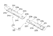
図2は本発明の第1の実施形態にかかるディスク装置のディスクガイド50及びゴムローラ19の形状を示す正面図であり、図3はディスクガイド50が取り付けられたクランプレバー25を、ディスクと当接する面側から見た斜視図である。図4Aは左ディスクガイド23及びゴムローラ19を、ゴムローラ19の軸に平行に切った断面図、図4Bは側面図である。図4A及び図4Bは、左ディスクガイド23側のみを示している。また、図5は左ディスクガイド23をディスクと当接する面側から見た斜視図である。   FIG. 2 is a front view showing the shapes of the disk guide 50 and the rubber roller 19 of the disk apparatus according to the first embodiment of the present invention. FIG. 3 abuts the clamp lever 25 to which the disk guide 50 is attached to the disk. It is the perspective view seen from the surface side. 4A is a cross-sectional view of the left disc guide 23 and the rubber roller 19 cut in parallel to the axis of the rubber roller 19, and FIG. 4B is a side view. 4A and 4B show only the left disc guide 23 side. FIG. 5 is a perspective view of the left disc guide 23 as seen from the side that contacts the disc.

ディスクガイド50は、左ディスクガイド23及び右ディスクガイド24で構成されている。左ディスクガイド23と右ディスクガイド24とは、ディスク挿入口44の長手方向の中間部をディスク挿入方向42に通る直線に対してほぼ左右対称に形成されて、クランプレバー25に取り付けられている。このように取り付けられた状態で、左ディスクガイド23及び右ディスクガイド24の延在方向、つまりディスク挿入方向42と交差する方向で且つ互いに遠い側(以下、外側という)の端部間の距離は、大径ディスクの直径以上の長さとなるように設けられている。クランプレバー25は、例えば剛性の高い板金で構成されており、クランプレバー25の取付け面25dはフラットに形成されている。   The disc guide 50 includes a left disc guide 23 and a right disc guide 24. The left disc guide 23 and the right disc guide 24 are attached to the clamp lever 25 so as to be substantially symmetrical with respect to a straight line that passes through the intermediate portion in the longitudinal direction of the disc insertion slot 44 in the disc insertion direction 42. The distance between the extending direction of the left disc guide 23 and the right disc guide 24, that is, the direction intersecting the disc insertion direction 42 and distant from each other (hereinafter referred to as the outside) is as follows. The length is larger than the diameter of the large-diameter disk. The clamp lever 25 is made of, for example, a highly rigid sheet metal, and the mounting surface 25d of the clamp lever 25 is formed flat.

左ディスクガイド23は、図5に示すように、板状のガイド基板231と、ガイド基板231の一端部近傍に設けられた係合部の一例である第2フック23bと、ガイド基板231の他端部近傍に設けられた凸部23jと、第2フック23bと凸部23iとの中間部で且つガイド基板231の外周部に、ディスク挿入方向42に対して互いに対向するように設けられた、一対の第1フック23aとを備えている。   As shown in FIG. 5, the left disc guide 23 includes a plate-shaped guide substrate 231, a second hook 23 b that is an example of an engaging portion provided near one end of the guide substrate 231, and the guide substrate 231. Provided in the intermediate portion between the convex portion 23j provided in the vicinity of the end portion, the second hook 23b and the convex portion 23i and on the outer peripheral portion of the guide substrate 231 so as to face each other with respect to the disc insertion direction 42. And a pair of first hooks 23a.

凸部23jは、左ディスクガイド23がクランプレバー25に取り付けられたときに、左ディスクガイド23とクランプレバー25との傾斜角度が保てるような形状で形成されている。例えば、図5に示すようなディスク挿入方向42に延在する棒状体や、突起の集合体などにより形成されている。凸部23jの高さは、ディスクガイド23の反りによる変形よりも大きくなるように(例えば0.2mm程度)設けられている。凸部23jを設ける位置は、ガイド基板231のエッジより内側過ぎると、左ディスクガイド23がディスクと当接した際に接触面が多くなって、ディスクに傷を付けやすくなり、ガイド基板231のエッジに近過ぎると、成形時に生じるヒケにより肉厚が薄くなって、高さが無くなってしまうことがあるため、ガイド基板231のエッジよりもやや内側に設けることが好ましい。なお、通常、ディスクの情報はディスクの外周部より1mm以上内側の部分の範囲には記録されていない。したがって、左ディスクガイド23は、基本的には、ディスクの外周部の上エッジ100aと当接するが、少なくとも外周部より1mm以内の範囲でディスクと当接することが好ましい。
また、凸部23jは、ガイド基板231と一体的に形成されてもよいし、ガイド基板231ではなく、クランプレバー25に取り付けられても、クランプレバー25に一体的に形成されてもよい。
The convex portion 23j is formed in such a shape that the tilt angle between the left disc guide 23 and the clamp lever 25 can be maintained when the left disc guide 23 is attached to the clamp lever 25. For example, it is formed of a rod-like body extending in the disc insertion direction 42 as shown in FIG. The height of the convex portion 23j is provided so as to be larger than the deformation due to the warp of the disk guide 23 (for example, about 0.2 mm). If the position where the convex portion 23j is provided is too much inside the edge of the guide substrate 231, the contact surface increases when the left disc guide 23 comes into contact with the disc, and the disc is easily damaged. If the distance is too close, the thickness may be reduced due to sink marks generated during molding, and the height may be lost. Usually, the information on the disc is not recorded in the range of the portion 1 mm or more inside from the outer peripheral portion of the disc. Therefore, the left disc guide 23 basically abuts on the upper edge 100a of the outer peripheral portion of the disc, but preferably abuts on the disc at least within a range of 1 mm from the outer peripheral portion.
Further, the convex portion 23j may be formed integrally with the guide substrate 231, or may be attached to the clamp lever 25 instead of the guide substrate 231, or may be formed integrally with the clamp lever 25.

第1フック23aは、一対の部材で構成されることに限定されず、左ディスクガイド23がクランプレバー25に取り付けられたときに、左ディスクガイド23とクランプレバー25との傾斜角度が保てるような形状であればよい。また、第1フック23aは、第2フック23bと一体的に形成されてもよい。ガイド基板231の凸部23jと第1フック23aとの間には、円柱状の位置決めピン23iが設けられている。位置決めピン23iは、第2フック23bと共働して左ディスクガイド23をクランプレバー25に位置決めするものである。   The first hook 23a is not limited to be composed of a pair of members, and when the left disc guide 23 is attached to the clamp lever 25, the inclination angle between the left disc guide 23 and the clamp lever 25 can be maintained. Any shape is acceptable. Further, the first hook 23a may be formed integrally with the second hook 23b. A cylindrical positioning pin 23i is provided between the convex portion 23j of the guide substrate 231 and the first hook 23a. The positioning pin 23 i cooperates with the second hook 23 b to position the left disc guide 23 on the clamp lever 25.

左ディスクガイド23の、後述する突条23c〜23fと対応する位置には、ヒケを防止するための溝23kが設けられている。また、左ディスクガイド23の、右ディスクガイド24に近づく側で且つディスク挿入方向42の下流側には、斜めに切り欠き23hが設けられている。切り欠き23hは、ディスク装着準備位置に装着された小径ディスクの外周部と略一致する位置に設けられ、小径ディスクの排出時に、小径ディスクが左ディスクガイド23に当たって傷が入るのを防ぐために設けられている。また、クランプレバー25の取付け面25dには、第2フック23bがクランプレバー25の取付け面25dの裏側の面から飛び出ないように半抜き加工25eが施されている。   A groove 23k for preventing sink marks is provided at a position of the left disc guide 23 corresponding to the protrusions 23c to 23f described later. Further, an oblique cutout 23h is provided on the left disc guide 23 on the side closer to the right disc guide 24 and on the downstream side in the disc insertion direction 42. The notch 23h is provided at a position substantially coincident with the outer peripheral portion of the small-diameter disk mounted at the disk mounting preparation position, and is provided to prevent the small-diameter disk from hitting the left disk guide 23 and being damaged when the small-diameter disk is ejected. ing. Further, the mounting surface 25d of the clamp lever 25 is subjected to a half punching process 25e so that the second hook 23b does not protrude from the surface on the back side of the mounting surface 25d of the clamp lever 25.

板状のガイド基板231の、凸部23j、第1フック23a及び第2フック23bが設けられている面と反対側の面で且つディスク挿入方向42に対して互いに対向する外周部分には、図3に示すように、突条(突出した筋道)23c,23d,23e,23fが形成されている。突条23c,23dは、クランプレバー25に取り付けられたときに、ディスク挿入方向42の上流側に位置するように設けられ、突条23e,23fはディスク挿入方向42の下流側に位置するように設けられている。また、突条23d,23fは、右ディスクガイド24より遠ざかる側に位置するように設けられ、突条23c,23eは右ディスクガイド24に近づく側に位置するように設けられている。   On the outer peripheral portion of the plate-shaped guide substrate 231 that is opposite to the surface on which the convex portions 23j, the first hooks 23a, and the second hooks 23b are provided and that faces each other with respect to the disc insertion direction 42, FIG. As shown in FIG. 3, ridges (protruding muscle paths) 23c, 23d, 23e, and 23f are formed. The protrusions 23c and 23d are provided so as to be positioned upstream of the disk insertion direction 42 when attached to the clamp lever 25, and the protrusions 23e and 23f are positioned downstream of the disk insertion direction 42. Is provided. Further, the protrusions 23d and 23f are provided so as to be located on the side away from the right disk guide 24, and the protrusions 23c and 23e are provided so as to be located on the side approaching the right disk guide 24.

突条23c〜23fは、右ディスクガイド24に近い側から外側に向かうに従い、ゴムローラ19に近づくように突出している。すなわち、突条23c〜23fは、右ディスクガイド24に近い側の肉厚が薄く、外側に向かうに従い、肉厚を次第に増していくように形成されている。突条23dのガイド基板231に対する傾斜角度は、突条23cのガイド基板231に対する傾斜角度よりも大きく、突条23fのガイド基板231に対する傾斜角度は、突条23eのガイド基板231に対する傾斜角度よりも大きく形成されている。例えば、突条23d,23fのガイド基板231に対する傾斜角度は2度程度であり、突条23c,23eのガイド基板231に対する傾斜角度は1度程度である。また、突条23e,23fの高さは、突条23c,23dの高さより低く形成されている。また、突条23c〜23fの断面は、図4Bに示すように、円弧状の山形に形成されている。これら突条23c〜23fの頂部(以下、稜線部という)23c−1〜23f−1の起伏はクランプレバー25に取り付けられてない状態では直線状に形成されている。   The protrusions 23c to 23f protrude so as to approach the rubber roller 19 from the side close to the right disc guide 24 toward the outside. That is, the protrusions 23c to 23f are formed so that the thickness near the right disc guide 24 is thin, and the thickness is gradually increased toward the outside. The inclination angle of the protrusion 23d with respect to the guide substrate 231 is larger than the inclination angle of the protrusion 23c with respect to the guide substrate 231. The inclination angle of the protrusion 23f with respect to the guide substrate 231 is larger than the inclination angle of the protrusion 23e with respect to the guide substrate 231. Largely formed. For example, the inclination angle of the protrusions 23d and 23f with respect to the guide substrate 231 is about 2 degrees, and the inclination angle of the protrusions 23c and 23e with respect to the guide substrate 231 is about 1 degree. Moreover, the height of the protrusions 23e and 23f is formed lower than the height of the protrusions 23c and 23d. Further, the cross sections of the protrusions 23c to 23f are formed in an arcuate mountain shape as shown in FIG. 4B. The undulations of the top portions (hereinafter referred to as ridge portions) 23c-1 to 23f-1 of the protrusions 23c to 23f are formed in a straight line when not attached to the clamp lever 25.

突条23e、23fと突条23c、23dの間には、外側に向かうに従い、径が太くなっているゴムローラ19の外側端部が、図4Bに示すように、上下方向に入り込めるように谷間23gが形成されている。これにより、薄いディスクが挿入されても、ゴムローラ19と左ディスクガイド23との間で確実に挟持することができるようになっている。谷間23gの外側端部の近傍部分は、ゴムローラ19の外側端部近傍と接触して、ゴムローラ19を待機状態で変形させないように、外側に向かうに従い、次第に薄くなるように形成されている。   Between the protrusions 23e and 23f and the protrusions 23c and 23d, as shown in FIG. 4B, the outer end portion of the rubber roller 19 whose diameter increases as it goes outward, the valley 23g Is formed. Thus, even when a thin disk is inserted, the rubber roller 19 and the left disk guide 23 can be securely clamped. The vicinity of the outer end of the valley 23g is formed so as to gradually become thinner toward the outside so as to contact the vicinity of the outer end of the rubber roller 19 and not to deform the rubber roller 19 in a standby state.

左ディスクガイド23は、以上のように構成されている。
なお、本発明の第1の実施形態においては、右ディスクガイド24は、左ディスクガイド23と、ディスク挿入口42の中央部をディスク挿入方向42に通る直線に対してほぼ左右対称に形成されており、右ディスクガイド24のガイド基板241、第1フック24a、第2フック24b、突条24c〜24f、谷間24g、切り欠き24h、位置決めピン24i、凸部24j、及び溝24kは、それぞれ左ディスクガイド23のガイド基板231、第1フック23a、第2フック23b、突条23c〜23f、谷間23g、切り欠き23h、位置決めピン23i、凸部23j及び溝23kと対応するため、説明を省略する。
The left disc guide 23 is configured as described above.
In the first embodiment of the present invention, the right disc guide 24 is formed substantially symmetrically with respect to the left disc guide 23 and a straight line passing through the center portion of the disc insertion slot 42 in the disc insertion direction 42. The guide board 241, the first hook 24a, the second hook 24b, the ridges 24c to 24f, the valleys 24g, the notches 24h, the positioning pins 24i, the protrusions 24j, and the grooves 24k of the right disk guide 24 are respectively provided on the left disk. Since it corresponds to the guide substrate 231, the first hook 23a, the second hook 23b, the protrusions 23c to 23f, the valley 23g, the notch 23h, the positioning pin 23i, the convex portion 23j, and the groove 23k of the guide 23, the description is omitted.

なお、本発明の第1の実施形態においては、ガイド基板231,241、突条23c〜23f,24c〜24f、谷間23g,24g、切り欠き23h,24h、位置決めピン23i,24i、及び溝23k,24kによりガイド部材の一例が構成されている。
また、本発明の第1の実施形態においては、左ディスクガイド23と右ディスクガイド24とを、ディスク挿入口42の中央部をディスク挿入方向42に通る直線に対してほぼ左右対称に設けたが、本発明はこれに限定されるものではない。つまり、完全な左右対称に形成されていなくてもよい。
また、本発明の第1の実施形態においては、左ディスクガイド23と右ディスクガイド24を取り付けるディスクガイド固定部材は、クランプレバー25が一体的に備えるように構成したが、筐体60が一体的に備えるように構成されてもよい。つまり、左ディスクガイド23と右ディスクガイド24とは、筐体60に取り付けられてもよい。
In the first embodiment of the present invention, the guide substrates 231 and 241, the ridges 23c to 23f and 24c to 24f, the valleys 23g and 24g, the notches 23h and 24h, the positioning pins 23i and 24i, and the grooves 23k, An example of the guide member is configured by 24k.
In the first embodiment of the present invention, the left disc guide 23 and the right disc guide 24 are provided substantially symmetrically with respect to a straight line passing through the central portion of the disc insertion slot 42 in the disc insertion direction 42. However, the present invention is not limited to this. That is, it does not have to be completely symmetrical.
In the first embodiment of the present invention, the disc guide fixing member for attaching the left disc guide 23 and the right disc guide 24 is configured so that the clamp lever 25 is integrally provided, but the housing 60 is integrally provided. It may be configured to prepare for. That is, the left disc guide 23 and the right disc guide 24 may be attached to the housing 60.

以上のように構成された本発明の第1の実施形態にかかるディスク装置のディスクガイド50に関して、その動作及び各部の作用効果を図6A、図6B、図7A及び図7Bを参照しつつ説明する。図6Aは本発明の第1の実施形態にかかるディスク装置のローディング開始時の、ディスクガイドとゴムローラに挟まれた大径ディスク100の状態を示す正面(ディスクのみ断面図で示す)であり、図6Bはローディング途中の、ディスクガイドとゴムローラに挟まれた大径ディスク100の状態を示す断面図である。図7Aは、左ディスクガイド23を示す正面図であり、図7Bは、左ディスクガイド23の取付け状態を示す断面図である。   With respect to the disk guide 50 of the disk apparatus according to the first embodiment of the present invention configured as described above, the operation and the effect of each part will be described with reference to FIGS. 6A, 6B, 7A and 7B. . FIG. 6A is a front view (only the disk is shown in a sectional view) showing a state of the large-diameter disk 100 sandwiched between the disk guide and the rubber roller at the start of loading of the disk device according to the first embodiment of the present invention. 6B is a cross-sectional view showing a state of the large-diameter disk 100 sandwiched between the disk guide and the rubber roller during loading. FIG. 7A is a front view showing the left disc guide 23, and FIG. 7B is a cross-sectional view showing a state in which the left disc guide 23 is attached.

使用者によって、ディスク挿入口44からディスク挿入方向42に大径ディスク100が挿入されると、大径ディスク100は、ディスクガイド50とゴムローラ19との間に挟まれて、前記ディスク搬送装置によってディスク挿入方向42に搬送される。   When the user inserts the large-diameter disk 100 in the disk insertion direction 42 from the disk insertion port 44, the large-diameter disk 100 is sandwiched between the disk guide 50 and the rubber roller 19, and the disk conveying device causes the disk to be It is conveyed in the insertion direction 42.

このとき、ディスクガイド50は、ディスク挿入口44の長手方向の中間部をディスク挿入方向42に通る直線側(以下、中央部側という)から外側に向かう従い、大径ディスク100に近づく方向、つまりクランプレバー25から遠ざかる方向に傾斜するように形成されているため、常に、大径ディスク100の上面(レーベル面)の上エッジ部分100aのみと当接して、大径ディスク100の移動をガイドする。また、ゴムローラ19も同様に、中央部側から外側に向かう従い、大径ディスク100に近づく方向に傾斜するように形成されているため、常に、ディスク100の記録面側の下エッジ部分100bのみと当接して大径ディスク100を搬送していく。したがって、大径ディスク100は、ディスクガイド50とゴムローラ19とに対して、常にエッジ部分100a,100bで当接しており、大径ディスク100の内側はディスクガイド50とゴムローラ19と当接することが無い。また、ディスクガイド50の外側の端部から端部までの距離が、ディスク100の直径以上の長さとなるように設けられているので、ディスクガイド50のエッジ部分23l,24lが大径ディスク100の内側に当接することは無い。よって、大径ディスク100の内側に傷が生じることは無い。   At this time, the disc guide 50 follows the direction from the straight side (hereinafter referred to as the center side) passing through the intermediate portion in the longitudinal direction of the disc insertion port 44 in the disc insertion direction 42 to the outside, that is, the direction approaching the large-diameter disc 100, that is, Since it is formed so as to incline away from the clamp lever 25, it always contacts only the upper edge portion 100a of the upper surface (label surface) of the large-diameter disk 100 to guide the movement of the large-diameter disk 100. Similarly, since the rubber roller 19 is formed so as to incline in the direction approaching the large-diameter disk 100 from the center side toward the outside, only the lower edge portion 100b on the recording surface side of the disk 100 is always included. The large-diameter disk 100 is conveyed in contact. Therefore, the large-diameter disk 100 is always in contact with the disk guide 50 and the rubber roller 19 at the edge portions 100 a and 100 b, and the inner side of the large-diameter disk 100 is not in contact with the disk guide 50 and the rubber roller 19. . Further, since the distance from the outer end of the disc guide 50 to the end is longer than the diameter of the disc 100, the edge portions 23 l and 24 l of the disc guide 50 are provided on the large-diameter disc 100. There is no contact inside. Therefore, no scratch is generated inside the large-diameter disk 100.

しかしながら、図6Aに示すように、大径ディスク100の搬送開始時はディスクガイド50の中央部側の薄肉部分と大径ディスク100との距離が非常に近いため、ディスクガイド50の薄肉部分が変形を起こすと、大径ディスク100の内側と当接する恐れが生じる。また、大径ディスク100を下から押し上げるゴムローラ19は、ディスク搬送力を得るために柔らかいゴムで形成されているため、実際は、大径ディスク100への押圧力により変形して、大径ディスク100の下エッジ部分100bより若干内側を押し上げている。   However, as shown in FIG. 6A, when the large-diameter disk 100 is started to be transported, the thin-walled portion of the disk guide 50 is deformed because the distance between the thin-walled portion on the center side of the disk guide 50 and the large-diameter disk 100 is very short. If this occurs, there is a risk of contact with the inside of the large-diameter disk 100. Further, since the rubber roller 19 that pushes up the large-diameter disk 100 from below is formed of soft rubber to obtain a disk conveying force, it is actually deformed by the pressing force to the large-diameter disk 100 and The inner side is pushed up slightly from the lower edge portion 100b.

このため、大径ディスク100は、上エッジ部分100aがディスクガイド50に当接して動かず、下エッジ部分100bより若干内側が押し上げられるため、大径ディスク100の中央部が上方向45に(山型に)反るように変形する。よって、大径ディスク100は、外周に向かうに従い、ディスクガイド50の突条23a〜23f,24a〜24fの傾斜に沿うように反ることになる。この反りは、ディスクガイド50との当接位置が外側に向かう程、傾斜が大きくなり、図6Bに示すように、大径ディスク100の上エッジ部分100aがディスクガイド50に当接した状態が、最も傾斜が大きくなる。したがって、大径ディスク100の上面とディスクガイド50との隙間が小さくなる。また、ディスクガイド50の外側部分は厚肉となっているため、ヒケや反り等が生じやすく、ヒケや反り等の変形を起こすと、突条23c〜23f,24c〜24fの高さが失われて、大径ディスク100とディスクガイド23の突条23c〜23f,24c〜24fとの隙間が無くなり、大径ディスク100に傷がつく恐れが生じる。   For this reason, the large-diameter disk 100 does not move because the upper edge portion 100a abuts on the disk guide 50 and is pushed slightly inward from the lower edge portion 100b. Deforms to warp. Therefore, the large-diameter disk 100 warps along the inclination of the protrusions 23a to 23f and 24a to 24f of the disk guide 50 as it goes to the outer periphery. The warpage increases as the abutting position with the disk guide 50 moves outward, and the state in which the upper edge portion 100a of the large-diameter disk 100 is in contact with the disk guide 50 as shown in FIG. The slope is the largest. Therefore, the gap between the upper surface of the large-diameter disk 100 and the disk guide 50 is reduced. Further, since the outer portion of the disc guide 50 is thick, sink marks and warpage are likely to occur. If deformation such as sink marks or warpage occurs, the heights of the protrusions 23c to 23f and 24c to 24f are lost. As a result, gaps between the large diameter disk 100 and the protrusions 23c to 23f and 24c to 24f of the disk guide 23 are eliminated, and the large diameter disk 100 may be damaged.

このため、本発明の第1の実施形態にかかるディスクガイド50においては、左ディスクガイド23のクランプレバー25への取付け側の面は、ヒケを防ぐための溝23kを除いてフラットに形成されており、上述のように凸部23j、第1フック23a及び第2フック23bがそれぞれ設けられている。また、右ディスクガイド24にも同様に、凸部24j、第1フック24a及び第2フック24bが設けられている。以下、右ディスクガイド24の構成及び作用効果は、左ディスクガイド23と同様であるので、左ディスクガイド23についてのみ説明する。   For this reason, in the disc guide 50 according to the first embodiment of the present invention, the surface of the left disc guide 23 on the mounting side to the clamp lever 25 is formed flat except for the groove 23k for preventing sink marks. As described above, the convex portion 23j, the first hook 23a, and the second hook 23b are provided. Similarly, the right disc guide 24 is provided with a convex portion 24j, a first hook 24a, and a second hook 24b. In the following, since the configuration and operational effects of the right disc guide 24 are the same as those of the left disc guide 23, only the left disc guide 23 will be described.

図7Bに示すように、左ディスクガイド23の凸部23jはクランプレバー25の取付け面25dと当接して突っ張り、第1フック23a及び第2フック23bはクランプレバー25に係合して、左ディスクガイド23の中央部側の部分を取付け面25d側に引き寄せている。これにより、左ディスクガイド23は、外側が取付け面25dから遠ざかる方向に弓なりに変形してクランプレバー25に取り付いている。左ディスクガイド23は樹脂で形成されており、弾性的に変形するため、その弾性力で第2フック23b近傍と凸部23jとを取付け面25dに押し付けている。   As shown in FIG. 7B, the convex portion 23j of the left disc guide 23 abuts against the mounting surface 25d of the clamp lever 25, and the first hook 23a and the second hook 23b engage with the clamp lever 25 to The central portion of the guide 23 is drawn toward the mounting surface 25d. Thus, the left disc guide 23 is attached to the clamp lever 25 by being deformed like a bow in the direction in which the outer side is away from the mounting surface 25d. The left disc guide 23 is made of resin, and is elastically deformed. Therefore, the elastic force of the left disc guide 23 presses the vicinity of the second hook 23b and the convex portion 23j against the mounting surface 25d.

よって、左ディスクガイド23は、ガタつき無くクランプレバー25に取り付けられるとともに、薄肉になっている第2フック23b近傍も浮き上がる事は無い。また、仮に浮き上がる力が作用しても第2フック23bにより、浮き上がりが規制されるため、大径ディスク100と当接することは無い。また、凸部23jの高さはガイド23の反り精度より大きく設けられているため、常に左ディスクガイド23は弾性的に変形をしてガタつき無く固定される。また、突条23c,23dの稜線部23c−1,23d−1の起伏は、単体では直線状に形成されているが、クランプレバー25に取り付いた状態では外側に向かうに従って、傾斜が大きくなる方向に変形するので、大径ディスク100がゴムローラ19に押されて上方向42に変形しても、大径ディスク100と突条23c,23dとの間には隙間を確保することができる。また、突条23dのガイド基板231に対する傾斜角を、突条23cのガイド基板231に対する傾斜角より大きくしているため、さらに、大径ディスク100と突条23c,23dとの隙間を確保できる。   Therefore, the left disc guide 23 is attached to the clamp lever 25 without rattling, and the vicinity of the thin second hook 23b does not rise. Even if a lifting force acts, the second hook 23b restricts the lifting, so that it does not come into contact with the large-diameter disk 100. Further, since the height of the convex portion 23j is larger than the warpage accuracy of the guide 23, the left disc guide 23 is always elastically deformed and fixed without rattling. Further, the undulations of the ridge portions 23c-1 and 23d-1 of the ridges 23c and 23d are formed in a straight line as a single unit, but in a state where they are attached to the clamp lever 25, the inclination increases toward the outside. Therefore, even if the large-diameter disk 100 is pushed by the rubber roller 19 and deformed in the upward direction 42, a gap can be secured between the large-diameter disk 100 and the protrusions 23c and 23d. In addition, since the inclination angle of the protrusion 23d with respect to the guide substrate 231 is larger than the inclination angle of the protrusion 23c with respect to the guide substrate 231, a gap between the large-diameter disk 100 and the protrusions 23c and 23d can be further secured.

なお、左ディスクガイド23の稜線部23c−1,23d−1の起伏を、最初から円弧状に形成したり、いくつかの直線を組み合わせることにより、中央部側から外側に向かうに従い傾斜を大きくするように形成して、同様の効果を得ることも可能である。しかしながら、ヒケ等の局部的な変形に対して寸法管理が難しいため好ましくない。局部的なヒケにより、突条23c〜23fのガイド基板231に対する傾斜角度が小さくなると、そのヒケを生じた部分において、大径ディスク100と左ディスクガイド23との隙間が無くなり、大径ディスク100の内側に容易に傷がつきやすい。このため、本発明の第1の実施形態の左ディスクガイド23のように、突条23c〜23fの稜線部23c−1〜23f−1の起伏を直線状に形成することが好ましい。突条23c〜23fの稜線部23c−1〜23f−1の起伏を直線状に形成することによって、寸法管理が容易となり、ヒケや反り等の成形不良を容易に検出することも可能となる。   In addition, the undulations of the ridge line portions 23c-1 and 23d-1 of the left disc guide 23 are formed in an arc shape from the beginning, or by combining several straight lines, the inclination is increased toward the outside from the central portion side. It is also possible to obtain the same effect by forming as described above. However, it is not preferable because dimensional management is difficult for local deformation such as sink marks. When the inclination angle of the protrusions 23c to 23f with respect to the guide substrate 231 is reduced due to local sinks, there is no gap between the large-diameter disk 100 and the left disk guide 23 in the portion where the sink marks are generated. Easily scratched inside. For this reason, it is preferable to form the undulations of the ridge line portions 23c-1 to 23f-1 of the ridges 23c to 23f in a straight line like the left disk guide 23 of the first embodiment of the present invention. By forming the ridges of the ridges 23c-1 to 23f-1 of the ridges 23c to 23f in a straight line, dimensional management is facilitated, and molding defects such as sink marks and warpage can be easily detected.

以上のように、本発明の第1の実施形態にかかるディスク装置によれば、ディスクガイド50の突条23c〜23f,24c〜24fの稜線部23c−1〜23f−1,24c−1〜24f−1の起伏を直線状に形成し、中央部側の端部に第2フック23b,24bを設け、外側の端部に凸部23j、24jを設け、さらに第2フック23b,24bと凸部23j,24jとの間に第1フック23a,24aを設けることにより、ガタつきや浮きを生じることなく、ディスクガイド50がクランプレバー25に固定される。
また、ディスクガイド50を、最初から円弧状に形成したり、肉厚を変化させることなく、外側に向かうに従い、大径ディスク100に対する傾斜を大きくすることができるため、簡単な構成でディスクに対して傷が付き難くすることが可能である。
また、クランプレバー25に固定するための第1フック23a,24a又は第2フック23b,24bが左ディスクガイド23又は右ディスクガイド24の周縁部より内側に形成されている場合には、成形の金型に第1フック23a,24a又は第2フック23b,24b形成用の穴を設ける必要があり、その穴のために成型時に樹脂が回りこめず、食いきりが生じる場合がある。これに対して、本発明の第1の実施形態にかかるディスク装置によれば、クランプレバー25に固定するための第1フック23a,24a又は第2フック23b,24bが左ディスクガイド23又は右ディスクガイド24の周縁部から外側に向かうよう(例えば、図5では、第1フック23a,24aは右上向き、第2フック23bは左上向き、第2フック24bは右下向き)に形成されているので、食いきりが無く、成形時の樹脂の流れが素直になり、部材の成形精度が向上する。また、ディスクガイド50が左ディスクガイド23と右ディスクガイド24の2つの部材で構成されることにより、一つの部材の長さが短くなり、また、ディスクと当接する突条23c〜23f,24c〜24fの稜線部23c−1〜23f−1,24c−1〜24f−1の起伏が直線状に形成されているので、さらに部材の成形精度が向上する。したがって、ディスクガイド50は品質が安定する。
また、外側の端部に設けた凸部23j,24により、傾斜の角度が必要な外側に向かうに従い傾斜を大きくでき、ディスクガイド50の全長にわたって傾斜を大きく形成する必要がないので、装置の薄型化が容易になる。
As described above, according to the disk device according to the first embodiment of the present invention, the ridge portions 23c-1 to 23f-1 and 24c-1 to 24f of the protrusions 23c to 23f and 24c to 24f of the disk guide 50 are provided. -1 is formed in a straight line, the second hooks 23b and 24b are provided at the end on the center side, the projections 23j and 24j are provided at the outer end, and the second hooks 23b and 24b and the projections are provided. By providing the first hooks 23a and 24a between 23j and 24j, the disc guide 50 is fixed to the clamp lever 25 without causing rattling or lifting.
Further, since the disc guide 50 can be increased in inclination with respect to the large-diameter disc 100 toward the outside without forming an arc shape from the beginning or changing the thickness, the disc guide 50 can be easily configured with respect to the disc. It is possible to make it difficult to be damaged.
In addition, when the first hooks 23a, 24a or the second hooks 23b, 24b for fixing to the clamp lever 25 are formed inside the peripheral edge of the left disc guide 23 or the right disc guide 24, the molding gold It is necessary to provide holes for forming the first hooks 23a, 24a or the second hooks 23b, 24b in the mold, and the resin may not wrap around at the time of molding due to the holes, which may cause biting. On the other hand, according to the disk device according to the first embodiment of the present invention, the first hooks 23a, 24a or the second hooks 23b, 24b for fixing to the clamp lever 25 are the left disk guide 23 or the right disk. Since it is formed so as to go outward from the peripheral edge of the guide 24 (for example, in FIG. 5, the first hooks 23a, 24a are directed to the upper right, the second hook 23b is directed to the upper left, and the second hook 24b is directed to the lower right) There is no biting, the flow of resin during molding is straightened, and the molding accuracy of the members is improved. Further, since the disc guide 50 is composed of two members, the left disc guide 23 and the right disc guide 24, the length of one member is shortened, and the protrusions 23c to 23f, 24c to abut against the disc. Since the undulations of the ridge line portions 23c-1 to 23f-1 and 24c-1 to 24f-1 of 24f are formed in a straight line, the molding accuracy of the member is further improved. Therefore, the quality of the disc guide 50 is stabilized.
Further, the convex portions 23j and 24 provided on the outer end portions can increase the inclination as the inclination angle goes to the required outer side, and it is not necessary to form a large inclination over the entire length of the disk guide 50. It becomes easy.

また、ディスク挿入方向42の上流側の突条23c,24c,23d,24dは、ディスク挿入方向42の下流側の突条23e,24e,23f,24fよりも高く形成されているため、ディスクは、この突条23c〜23f,24c〜24fに沿って、ディスク挿入方向42の下流側に向かって上方向45にガイドされる。これにより、ディスクとターンテーブル3との隙間が確保され、ディスクの内側に傷を付ける恐れがない。   Further, since the ridges 23c, 24c, 23d, 24d on the upstream side in the disk insertion direction 42 are formed higher than the ridges 23e, 24e, 23f, 24f on the downstream side in the disk insertion direction 42, the disk is It is guided in the upward direction 45 toward the downstream side of the disk insertion direction 42 along the protrusions 23c to 23f and 24c to 24f. Thereby, the clearance gap between a disc and the turntable 3 is ensured, and there is no possibility of scratching the inside of a disc.

次に、ディスクガイド50の、ディスク挿入方向42の下流側の突条23e,24e,23f,24fの形状について、図6B、図8A、図8B及び図8Cを参照しつつ、さらに詳しく説明する。図8Aは本発明の第1の実施形態にかかるディスク装置の大径ディスク100のローディング動作途中の状態を示す一部側断面図、図8Bは大径ディスク100がターンテーブル3の面にほぼ平行に装着され保持された状態を示す一部側断面図であり、図8Cは大径ディスク100の再生又は記録中に衝撃を受けるなどして振動し、大径ディスク100がクランプ状態でディスク挿入方向の上流側がターンテーブル3から浮いた状態を示す一部側断面図である。なお、左ディスクガイド23と右ディスクガイド24とは同様の構成及び作用効果を有しているので、以下には、左ディスクガイド23のみについて説明する。   Next, the shape of the protrusions 23e, 24e, 23f, and 24f on the downstream side of the disk insertion direction 42 of the disk guide 50 will be described in more detail with reference to FIGS. 6B, 8A, 8B, and 8C. FIG. 8A is a partial cross-sectional view showing a state in the middle of the loading operation of the large-diameter disk 100 of the disk apparatus according to the first embodiment of the present invention, and FIG. 8B is a diagram illustrating the large-diameter disk 100 substantially parallel to the surface of the turntable 3. 8C is a partial cross-sectional view showing a state where the large-diameter disc 100 is mounted and held, and FIG. 8C is oscillated by receiving an impact during reproduction or recording of the large-diameter disc 100. It is a partial sectional side view which shows the state which floated from the turntable 3 upstream. Since the left disc guide 23 and the right disc guide 24 have the same configuration and operational effects, only the left disc guide 23 will be described below.

ここで、ターンテーブル3は、前述したように、スピンドルモータ3Aを構成するロータにより構成されている。スピンドルモータ3Aは、図8A、図8B及び図8Cに示すように、ロータと、回転軸3cと、芯出しリング3dと、マグネット3eと、軸受3fと、コア3gと、コイル3hとにより構成されている。ロータ、つまりターンテーブル3は、下方に開口するカップ形状に形成され、上面にディスク100を載置するターンテーブル面3bを形成し、上面中央部に上方に突出する上部円筒状部を有している。回転体3cは、棒状に形成され、上端部をターンテーブル3の上部円筒状部の内周側を一体的に保持している。芯出しリング3dは、ターンテーブル3の、上部円筒状部の外周及びターンテーブル面3bの上部円筒状部近傍部分に取り付けられ、大径ディスク100の中心孔を保持して芯出しを行う。マグネット3eは、リング形状に形成され、ターンテーブル3の下部円筒状部の内周面に設けられている。た軸受3fは、円筒形状に形成されて支持基板1に一体的に設けられ、回転軸3cの下端部をその内周面で回転自在に保持している。コア3gは、マグネット3eの内周面と対向するように軸受3fの外周面に固定されている。コイル3hは、コア3gの周囲に巻装されている。スピンドルモータ3Aは、コイル3hに電流が印加されることによりマグネット3eとコア3gとの間に発生する電磁気力によって、軸受3fを介して基板1に一体的に構成されたコア3gと対向するマグネット3eを回転させターンテーブル3を回転させるように構成されている。   Here, as described above, the turntable 3 is constituted by the rotor constituting the spindle motor 3A. As shown in FIGS. 8A, 8B, and 8C, the spindle motor 3A includes a rotor, a rotating shaft 3c, a centering ring 3d, a magnet 3e, a bearing 3f, a core 3g, and a coil 3h. ing. The rotor, that is, the turntable 3 is formed in a cup shape that opens downward, forms a turntable surface 3b on which the disk 100 is placed on the upper surface, and has an upper cylindrical portion protruding upward at the center of the upper surface. Yes. The rotating body 3c is formed in a rod shape and integrally holds the upper end portion on the inner peripheral side of the upper cylindrical portion of the turntable 3. The centering ring 3d is attached to the outer periphery of the upper cylindrical portion of the turntable 3 and the vicinity of the upper cylindrical portion of the turntable surface 3b, and performs centering while holding the center hole of the large-diameter disk 100. The magnet 3 e is formed in a ring shape, and is provided on the inner peripheral surface of the lower cylindrical portion of the turntable 3. The bearing 3f is formed in a cylindrical shape and is provided integrally with the support substrate 1, and rotatably holds the lower end portion of the rotating shaft 3c on its inner peripheral surface. The core 3g is fixed to the outer peripheral surface of the bearing 3f so as to face the inner peripheral surface of the magnet 3e. The coil 3h is wound around the core 3g. The spindle motor 3A has a magnet facing the core 3g integrally formed on the substrate 1 through the bearing 3f by an electromagnetic force generated between the magnet 3e and the core 3g when a current is applied to the coil 3h. It is comprised so that 3e may be rotated and the turntable 3 may be rotated.

大径ディスク100は、再生又は記録中、図8Bに示すような状態で、クランパ27によりターンテーブル3の上面3bにほぼ平行に保持された状態で回転する。この際、左ディスクガイド23の突条23eは、大径ディスク100の面から離れた位置に位置している。そして、大径ディスク100の回転中、大径ディスク100にはジャイロ効果が働いて、その姿勢を保とうとする力が働く。その際、ディスク装置に何らかの衝撃が加わり、ディスク装置が上下に振動すると、クランパ27のディスク押圧力がその振動力に負けて、ディスク100がターンテーブル3から離れる方向46(図8B参照)に浮き上がる状態が発生することがある。これにより、浮き上がった大径ディスク100は、図8Cに示すように、クランパ27の押圧力でターンテーブル3の上面3bに接触したままで、左ディスクガイド23の突条23eと当接する。つまり、左ディスクガイド23の突条23eは、回転中である大径ディスク100の上エッジ100aと当接することとなる。このエッジ100aが当接する位置は、図3に示す大径ディスク100の外周部と左ディスクガイド23の突条23eが交差する部分である。   During reproduction or recording, the large-diameter disc 100 rotates while being held substantially parallel to the upper surface 3b of the turntable 3 by the clamper 27 in the state shown in FIG. 8B. At this time, the protrusion 23 e of the left disk guide 23 is located at a position away from the surface of the large-diameter disk 100. During the rotation of the large-diameter disk 100, a gyro effect is applied to the large-diameter disk 100, and a force for maintaining the posture is applied. At that time, when some impact is applied to the disk device and the disk device vibrates up and down, the disk pressing force of the clamper 27 is lost to the vibration force, and the disk 100 is lifted in the direction 46 (see FIG. 8B) away from the turntable 3. A condition may occur. As a result, as shown in FIG. 8C, the lifted large-diameter disk 100 is in contact with the protrusion 23e of the left disk guide 23 while being in contact with the upper surface 3b of the turntable 3 by the pressing force of the clamper 27. That is, the protrusion 23e of the left disk guide 23 comes into contact with the upper edge 100a of the rotating large-diameter disk 100. The position where the edge 100a abuts is a portion where the outer peripheral portion of the large-diameter disk 100 shown in FIG.

仮に、左ディスクガイド23の突条23eが大径ディスク100の上エッジ100aと線接触するように形成されていると、大径ディスク100の上エッジ100aによって、左ガイド23の突条23eが削られて傷ができ、その傷に大径ディスク100が引っかかって排出できないことが起こり得る。このため、本発明の第1の実施形態にかかる左ディスクガイド23の突条23eには、図8Cに示すように、浮き上がった大径ディスク100の上面と広い範囲で接触するように、大径ディスク100の上エッジ100aによる突条23eの特に稜線部23e−1キズを防止するため、傾斜面23mが突条23eの稜線部23e−1よりディスク挿入方向42の下流側に形成されている。傾斜面23mは、図8Cに示すように、クランパ27の押圧力で大径ディスク100をターンテーブル3の上面3bに接触したままで、すなわちディスク記録再生位置において大径ディスク100のディスク挿入方向42の上流側が持ち上がって左ディスクガイド23の突条23eに当接した状態ときに、大径ディスク100とほぼ平行で且つ対向して位置可能であるように設けられている。また、この傾斜面23mは、大径ディスク100の上エッジ100a近傍のディスク挿入方向42の下流側が上流側より若干先当たりするよう形成されている。   If the protrusion 23e of the left disk guide 23 is formed so as to be in line contact with the upper edge 100a of the large-diameter disk 100, the protrusion 23e of the left guide 23 is shaved by the upper edge 100a of the large-diameter disk 100. It can happen that the large-diameter disk 100 is caught by the scratch and cannot be ejected. Therefore, the protrusion 23e of the left disk guide 23 according to the first embodiment of the present invention has a large diameter so as to come into contact with the upper surface of the floating large diameter disk 100 in a wide range as shown in FIG. 8C. In order to prevent the ridge 23e-1 from being scratched by the upper edge 100a of the disk 100, an inclined surface 23m is formed on the downstream side in the disk insertion direction 42 from the ridge 23e-1 of the ridge 23e. As shown in FIG. 8C, the inclined surface 23m keeps the large-diameter disk 100 in contact with the upper surface 3b of the turntable 3 by the pressing force of the clamper 27, that is, the disk insertion direction 42 of the large-diameter disk 100 at the disk recording / reproducing position. Is positioned so as to be substantially parallel to and opposed to the large-diameter disk 100 when the upstream side of the disk is lifted and abuts against the protrusion 23e of the left disk guide 23. The inclined surface 23m is formed so that the downstream side in the disc insertion direction 42 in the vicinity of the upper edge 100a of the large-diameter disc 100 slightly contacts the upstream side.

したがって、左ディスクガイド23の突条23eは、傾斜面23mにより大径ディスク100の上エッジ100aと傾斜面23mで面接触するため、削られる部分が分散されて、削られる量が少なくなる。これにより、大径ディスク100の上エッジ100aと対向する突条23eの一部に深い傷が入ることを防ぐことができ、大径ディスク100の排出時に、その傷に引っ掛ってディスク100が排出できないと言う不具合を起こすことを防ぐことができる。   Therefore, since the protrusion 23e of the left disk guide 23 is in surface contact with the upper edge 100a of the large-diameter disk 100 by the inclined surface 23m and the inclined surface 23m, the portion to be cut is dispersed and the amount to be cut is reduced. As a result, it is possible to prevent a deep flaw from entering a part of the ridge 23e facing the upper edge 100a of the large-diameter disc 100. When the large-diameter disc 100 is ejected, the disc 100 is ejected by being caught by the scar. It is possible to prevent the problem that it cannot be done.

なお、傾斜面23mのディスク挿入方向42の下流側が、大径ディスク100が衝撃・振動等で先当たりするように形成されることにより、突条23eの稜線部23e−1よりも先に大径ディスク100と接触するため、よりディスク排出不良を起こさない。例えば、傾斜面23mのディスク挿入方向42の下流側に凸部を設けることにより、一定勾配の傾斜面23mを設けなくても、同様の効果を得ることができる。これにより、突条23eの稜線部23e−1が削られることを防ぐことでディスク排出不良を防ぐことができる。   In addition, the downstream side of the inclined surface 23m in the disk insertion direction 42 is formed so that the large-diameter disk 100 comes into contact with impact, vibration, or the like, so that the diameter of the ridge 23e is larger than that of the ridge line portion 23e-1. Since it is in contact with the disc 100, the disc discharge defect is not caused more. For example, by providing a convex portion on the downstream side of the inclined surface 23m in the disc insertion direction 42, the same effect can be obtained without providing the inclined surface 23m with a constant gradient. Thereby, disc ejection failure can be prevented by preventing the ridge line portion 23e-1 of the ridge 23e from being cut.

なお、クランプレバー25のディスク挿入方向42の下流側に大径ディスク100と当接する凸部や傾斜を設けても、傾斜面23mと同様の効果を得られるが、クランプレバー25が板金で形成されているため、接触時の大径ディスク100の削れや異音が大きいことから、左ディスクガイド23に傾斜面23mを設けるほうが好ましい。
なお、小径ディスクとディスクガイド50との関係については、上述した大径ディスク100とディスクガイド50との関係と同様であるので、説明は省略する。
なお、本発明の第1の実施形態においては、この稜線部23c−1〜23f−1を含む突条23c〜23f及び傾斜面23mにより、ディスク当接面の一例が形成されている。
The same effect as that of the inclined surface 23m can be obtained by providing a convex portion or an inclination that contacts the large-diameter disk 100 on the downstream side in the disk insertion direction 42 of the clamp lever 25, but the clamp lever 25 is formed of a sheet metal. Therefore, it is preferable to provide the left disk guide 23 with an inclined surface 23m, since the large-diameter disk 100 is greatly scraped and has a strange noise during contact.
The relationship between the small-diameter disk and the disk guide 50 is the same as the relationship between the large-diameter disk 100 and the disk guide 50 described above, and a description thereof will be omitted.
In the first embodiment of the present invention, an example of a disk contact surface is formed by the ridges 23c to 23f including the ridge line portions 23c-1 to 23f-1 and the inclined surface 23m.

《第2の実施形態》
本発明の第2の実施形態にかかるディスク装置を、図9及び図10を参照しつつ説明する。図9は本発明の第2の実施形態にかかるディスク装置の分解斜視図である。図10は本発明の第2の実施形態にかかるディスク装置のディスクガイドが、クランプレバーに取り付けられた状態を示す正面図である。本発明の第2の実施形態にかかるディスク装置は、クランプレバー25、クランププレート26、ディスクガイド50に代えて、クランプレバー125、クランププレート126、ディスクガイド51を有する点で、本発明の第1の実施形態にかかるディスク装置と異なる。それ以外の点においては、本発明の第1の実施形態と同様であるので重複する説明は省略する。
<< Second Embodiment >>
A disk device according to a second embodiment of the present invention will be described with reference to FIGS. FIG. 9 is an exploded perspective view of the disk device according to the second embodiment of the present invention. FIG. 10 is a front view showing a state in which the disc guide of the disc device according to the second embodiment of the present invention is attached to the clamp lever. The disk device according to the second embodiment of the present invention includes a clamp lever 125, a clamp plate 126, and a disk guide 51 in place of the clamp lever 25, the clamp plate 26, and the disk guide 50. This is different from the disk device according to the embodiment. Since it is the same as that of the 1st Embodiment of this invention in other points, the overlapping description is abbreviate | omitted.

クランプレバー125は、支持基板1に平行で且つディスク挿入方向42と交差する方向に延在するように設けられ、ディスクガイド固定部の機能を有している。クランプレバー125は、その両端部に形成された軸受孔125a,125bに、支持基板1に設けられた、ローラレバー21と同じ回動軸(図示しない)が嵌合することにより、支持基板1に回動自在に支持されている。クランプレバー125は、一方の端部に形成されたピン125cが、カムロッド17のカム溝17cに係合することによって、その姿勢がコントロールされている。クランプレバー25の上面中央部には、ディスク挿入方向42の下流側に突出するように、弾性的な板バネで形成されたクランププレート126の一端部がネジ止めされている。クランププレート126の他端部は、その下面で円盤状のクランパ27を回動自在に支持している。クランプレバー125とクランププレート126とはクランプユニットの一例を構成している。モータ5の回転軸の回転力により、カムロッド17がディスク挿入方向42又はディスク排出方向43に移動すると、カムロッド17とカム溝17cで係合するクランプレバー125と、クランプレバー125に取り付けられたクランププレート126とは、クランプレバー125の軸受孔125a、125bが前記回動軸(図示しない)と嵌合している部分を中心に回動する。このとき、クランパ27は、下方向又は上方向に移動する。   The clamp lever 125 is provided so as to extend in a direction parallel to the support substrate 1 and intersecting the disc insertion direction 42, and has a function of a disc guide fixing portion. The clamp lever 125 is fitted to the support substrate 1 by fitting the same rotation shaft (not shown) as the roller lever 21 provided in the support substrate 1 into the bearing holes 125a and 125b formed at both ends thereof. It is supported rotatably. The clamp lever 125 is controlled in its posture by a pin 125 c formed at one end of the clamp lever 125 engaging with the cam groove 17 c of the cam rod 17. One end of a clamp plate 126 formed of an elastic leaf spring is screwed to the center of the upper surface of the clamp lever 25 so as to protrude downstream in the disc insertion direction 42. The other end of the clamp plate 126 supports a disc-shaped clamper 27 on its lower surface so as to be rotatable. The clamp lever 125 and the clamp plate 126 constitute an example of a clamp unit. When the cam rod 17 moves in the disc insertion direction 42 or the disc ejection direction 43 by the rotational force of the rotation shaft of the motor 5, the clamp lever 125 engaged with the cam rod 17 and the cam groove 17c, and the clamp plate attached to the clamp lever 125 126 rotates around a portion where the bearing holes 125a and 125b of the clamp lever 125 are fitted to the rotation shaft (not shown). At this time, the clamper 27 moves downward or upward.

ディスクガイド51は、クランプレバー125の下面に取り付けられ、バネ22により上方向に付勢されるゴムローラ19と協働してディスクを狭持し、ディスクをディスク挿入方向42に案内する。ディスクガイド51は、ディスクを傷つけないように、ディスクよりも柔らかい材料で形成されている。例えば、ディスクの材料がポリカーボネートであれば、それよりも柔らかいポリアセタール等の樹脂で形成されている。   The disk guide 51 is attached to the lower surface of the clamp lever 125 and cooperates with the rubber roller 19 urged upward by the spring 22 to pinch the disk and guide the disk in the disk insertion direction 42. The disc guide 51 is made of a material softer than the disc so as not to damage the disc. For example, if the material of the disk is polycarbonate, it is formed of a softer resin such as polyacetal.

ディスクガイド51は、大径ディスク100の直径以上の長さを有する長尺の板状の、ガイド部材の一例であるガイド基板123と、ガイド基板123の両端部近傍に設けられた凸部123bと、ガイド基板123の中央部123cに対してほぼ左右対称に設けられた、係合部の一例である一対のフック123aとを備えている。ディスクガイド51のクランプレバー125への取付け側の面はフラットに形成されている。   The disc guide 51 is a long plate-like guide substrate 123 having an length equal to or larger than the diameter of the large-diameter disc 100, and convex portions 123b provided near both ends of the guide substrate 123. A pair of hooks 123a, which are examples of engaging portions, are provided substantially symmetrically with respect to the central portion 123c of the guide substrate 123. The surface of the disc guide 51 on the side where the disc guide 51 is attached to the clamp lever 125 is formed flat.

凸部123bは、ディスクガイド51がクランプレバー125に取り付けられたときに、ディスクガイド51とクランプレバー125との傾斜角度が保てるような形状で形成されている。例えば、棒状体や突起の集合体などにより形成されている。凸部123bの高さは、ディスクガイド51の反りによる変形よりも大きくなるように(例えば0.2mm程度)設けられている。凸部123bを設ける位置は、ガイド基板123のエッジより内側過ぎると、ガイド基板123がディスクと当接した際に接触面が多くなってディスクに傷を付けやすくなり、ガイド基板123のエッジに近過ぎると、成形時に生じるヒケにより肉厚が薄くなって、高さが無くなってしまうことがあるため、ガイド基板123のエッジよりもやや内側に設けることが好ましい。また、凸部123bは、ガイド基板123と一体的に形成されてもよいし、ガイド基板123ではなく、クランプレバー125に取り付けられても、クランプレバー125に一体的に形成されてもよい。また、フック123aは、ガイド基板123の、中央部123c側よりも外側寄りに設けられることが好ましい。また、フック123aは、一対の部材で構成されることに限定されず、ディスクガイド51がクランプレバー125に取り付けられたときに、ディスクガイド51とクランプレバー125との傾斜角度が保てるような形状であればよい。
本発明の第2の実施形態にかかるディスク装置は、以上のように構成されている。
The convex portion 123 b is formed in such a shape that the tilt angle between the disc guide 51 and the clamp lever 125 can be maintained when the disc guide 51 is attached to the clamp lever 125. For example, it is formed of a rod-like body or an assembly of protrusions. The height of the convex portion 123b is provided to be larger than the deformation due to the warp of the disc guide 51 (for example, about 0.2 mm). If the position where the protrusion 123b is provided is too much inside the edge of the guide substrate 123, the contact surface increases when the guide substrate 123 comes into contact with the disk, and the disk is easily damaged, and is close to the edge of the guide substrate 123. If the thickness is too large, the thickness may be reduced due to sink marks generated at the time of molding, and the height may be lost. The convex portion 123b may be formed integrally with the guide substrate 123, or may be attached to the clamp lever 125 instead of the guide substrate 123, or may be formed integrally with the clamp lever 125. Moreover, it is preferable that the hook 123a is provided in the outer side rather than the center part 123c side of the guide board | substrate 123. FIG. In addition, the hook 123a is not limited to being configured by a pair of members, and has such a shape that the tilt angle between the disc guide 51 and the clamp lever 125 can be maintained when the disc guide 51 is attached to the clamp lever 125. I just need it.
The disk device according to the second embodiment of the present invention is configured as described above.

本発明の第2の実施形態にかかるディスク装置によれば、ディスクガイド51の凸部123bは、クランプレバー125の取付け面125dと当接して突っ張り、一対のフック125aはクランプレバー125に係合して、ガイド基板123の中央部123c近傍を取付け面125d側に引き寄せている。これにより、ディスクガイド123は外側が取付け面125dから遠ざかる方向に弓なりに変形してクランプレバー125に取り付いている。ディスクガイド51は樹脂で形成されており、弾性的に変形するため、その弾性力でディスクガイド51の中央部123c近傍と一対の凸部123bとを取付け面125dに押し付けている。したがって、ディスクガイド51は、ガタつき無くクランプレバー125に取り付けられる。また、ディスクガイド51の中央部123c近傍は浮き上がらないので、ガイド基板123の中央部123cがディスクと当接することは無い。また、凸部123bの高さはディスクガイド51の反り精度より大きく設けられているため、常にディスクガイド51は弾性的に変形をしてガタつき無く固定される。また、ディスクガイド51は、一対の凸部123bによって、外側に向かうに従い、ディスクに近づく方向に傾斜するように設けられているので、ディスクのエッジ部分のみと接触し、ディスクの内側を傷つけることはない。   According to the disk device according to the second embodiment of the present invention, the convex portion 123b of the disk guide 51 abuts against the mounting surface 125d of the clamp lever 125, and the pair of hooks 125a engage with the clamp lever 125. Thus, the vicinity of the central portion 123c of the guide substrate 123 is drawn toward the mounting surface 125d. Thus, the disk guide 123 is attached to the clamp lever 125 by deforming like a bow in the direction in which the outer side moves away from the mounting surface 125d. Since the disk guide 51 is made of resin and is elastically deformed, the vicinity of the center portion 123c of the disk guide 51 and the pair of convex portions 123b are pressed against the mounting surface 125d by the elastic force. Therefore, the disc guide 51 is attached to the clamp lever 125 without rattling. Further, since the vicinity of the central portion 123c of the disc guide 51 does not float, the central portion 123c of the guide substrate 123 does not come into contact with the disc. Further, since the height of the convex portion 123b is larger than the warp accuracy of the disk guide 51, the disk guide 51 is always elastically deformed and fixed without rattling. Further, the disk guide 51 is provided by the pair of convex portions 123b so as to be inclined in a direction approaching the disk as it goes outward, so that it contacts only the edge portion of the disk and damages the inside of the disk. Absent.

なお、ディスクガイド51のディスク当接面側に、ディスクガイド50に設けたような突条23c〜23f,24c〜24fを設けても良い。この場合、それぞれの突条23c〜23f,24c〜24fには、ディスクに当接される稜線部23c−1〜23f−1,24c−1〜24f−1が形成され、前述のようにディスク挿入方向42の下流側の突条23e,24eに、その稜線部23e−1,24e−1よりディスク挿入方向42の下流側に傾斜面23m,24mを形成することにより、前述の第1の実施形態と同様な作用効果を得ることができる。   Note that protrusions 23 c to 23 f and 24 c to 24 f as provided on the disk guide 50 may be provided on the disk contact surface side of the disk guide 51. In this case, the ridges 23c-1 to 23f-1 and 24c-1 to 24f-1 are formed on the protrusions 23c to 23f and 24c to 24f, respectively. By forming the inclined surfaces 23m and 24m on the downstream side of the disk insertion direction 42 from the ridges 23e-1 and 24e-1 on the ridges 23e and 24e on the downstream side in the direction 42, the first embodiment described above. The same effect can be obtained.

以上、本発明の実施形態について説明してきたが、本発明は上記各実施形態に限定されるものではなく、様々な変形が可能である。
また、上記各実施形態のうちの任意の実施形態を適宜組み合わせることにより、それぞれの有する効果を奏するようにすることができる。
As mentioned above, although embodiment of this invention has been described, this invention is not limited to said each embodiment, A various deformation | transformation is possible.
In addition, by appropriately combining arbitrary embodiments of the above-described embodiments, the effects possessed by them can be produced.

本発明のディスク装置は、CDやDVD等のディスク状の記録媒体を、トレイを用いずに装置内にローディングするスロットインローディング機構を備えるディスク装置に有用である。   The disk device of the present invention is useful for a disk device having a slot-in loading mechanism for loading a disk-shaped recording medium such as a CD or DVD into the device without using a tray.

本発明の第1の実施形態にかかるディスク装置の分解斜視図1 is an exploded perspective view of a disk device according to a first embodiment of the present invention. 本発明の第1の実施形態にかかるディスク装置のディスクガイドとゴムローラの形状を示す正面図The front view which shows the shape of the disk guide and rubber roller of the disk apparatus concerning the 1st Embodiment of this invention. 本発明の第1の実施形態にかかるディスク装置の、クランプレバーに取り付けられたディスクガイドを示す斜視図The perspective view which shows the disc guide attached to the clamp lever of the disc apparatus concerning the 1st Embodiment of this invention. 本発明の第1の実施形態にかかるディスク装置の左ディスクガイドとゴムローラの断面図Sectional drawing of the left disc guide and rubber roller of the disc apparatus concerning the 1st Embodiment of this invention 本発明の第1の実施形態にかかるディスク装置の左ディスクガイドとゴムローラの側面図The side view of the left disc guide and rubber roller of the disc apparatus concerning the 1st Embodiment of this invention 本発明の第1の実施形態にかかるディスク装置のディスクガイドのディスク当接面側を示す斜視図The perspective view which shows the disk contact surface side of the disk guide of the disk apparatus concerning the 1st Embodiment of this invention. 本発明の第1の実施形態にかかるディスク装置のローディング開始時の、ディスクガイドとゴムローラに挟まれた大径ディスクの状態を示す断面図Sectional drawing which shows the state of the large diameter disc pinched | interposed into the disc guide and the rubber roller at the time of the loading start of the disc apparatus concerning the 1st Embodiment of this invention 本発明の第1の実施形態にかかるディスク装置のローディング途中の、ディスクガイドとゴムローラに挟まれた大径ディスクの状態を示す断面図Sectional drawing which shows the state of the large diameter disc pinched | interposed into the disc guide and the rubber roller in the middle of loading of the disc apparatus concerning the 1st Embodiment of this invention 本発明の第1の実施形態にかかるディスク装置の左ディスクガイドを示す正面図1 is a front view showing a left disc guide of a disc device according to a first embodiment of the present invention. 本発明の第1の実施形態にかかるディスク装置の左ディスクガイドの取付け状態を示す断面図Sectional drawing which shows the attachment state of the left disc guide of the disc apparatus concerning the 1st Embodiment of this invention 本発明の第1の実施形態にかかるディスク装置の大径ディスクのローディング動作途中の状態を示す一部側断面図1 is a partial cross-sectional view showing a state in the middle of a loading operation of a large-diameter disk of a disk device according to a first embodiment of the present invention; 本発明の第1の実施形態にかかるディスク装置の大径ディスクがターンテーブルの面にほぼ平行に装着され保持された状態を示す一部側断面図1 is a partial sectional side view showing a state in which a large-diameter disk of a disk apparatus according to a first embodiment of the present invention is mounted and held substantially parallel to a surface of a turntable. 本発明の第1の実施形態にかかるディスク装置の大径ディスクの再生又は記録中に振動が加わり、大径ディスクがターンテーブルから浮いた状態を示す一部側断面図1 is a partial cross-sectional side view showing a state in which a large-diameter disk is lifted from a turntable when vibration is applied during reproduction or recording of the large-diameter disk of the disk apparatus according to the first embodiment of the present invention. 本発明の第2の実施形態にかかるディスク装置の分解斜視図The disassembled perspective view of the disc apparatus concerning the 2nd Embodiment of this invention. 本発明の第2の実施形態にかかるディスク装置の、クランプレバーに取り付けられたディスクガイドを示す正面図The front view which shows the disc guide attached to the clamp lever of the disc apparatus concerning the 2nd Embodiment of this invention.

符号の説明Explanation of symbols

1 支持基板
2 蓋体
2a ロック部
3 ターンテーブル
4 光ピックアップ
5 モータ
6 プーリ
7 ベルト
8 プーリ
9、12 はす歯ギヤ
10 ギヤ軸
11 ウォームギヤ
13、14 リレーギヤ
15 駆動ギヤ
16 ローラギヤ
17 カムロッド
17a、17b カム溝
17c ラック
18 ローラ軸
19 ゴムローラ
20 シャフトホルダ
21 ローラレバー
22、32、34、37 バネ
23 左ディスクガイド
23a、23b、24a、24b、123a フック
23c〜23f、24c〜24f 突条
24 右ディスクガイド
23g、24g 谷間
23h、24h 切り欠き
23i、24i 位置決めピン
23j、24j、123b 凸部
23k、24k 溝
23m、24m 傾斜面
23c−1〜23f−1、24c−1〜24f−1 稜線部
25、125 クランプレバー
25c ピン
25d、125d 取付け面
26、126 クランププレート
27 クランパ
28 ガイド
29 P板
30 左センタリングレバー
31 右センタリングレバー
33 ロックレバー
35 トリガーレバー
36 トリガーロッド
38 スイッチ
40、41 受光素子
50、51 ディスクガイド
60 筐体
DESCRIPTION OF SYMBOLS 1 Support substrate 2 Cover 2a Lock part 3 Turntable 4 Optical pick-up 5 Motor 6 Pulley 7 Belt 8 Pulley 9, 12 Helical gear 10 Gear shaft 11 Worm gear 13, 14 Relay gear 15 Drive gear 16 Roller gear 17 Cam rods 17a, 17b Cam Groove 17c Rack 18 Roller shaft 19 Rubber roller 20 Shaft holder 21 Roller levers 22, 32, 34, 37 Spring 23 Left disk guides 23a, 23b, 24a, 24b, 123a Hooks 23c-23f, 24c-24f Projection 24 Right disk guide 23g 24h Valley 23h, 24h Notch 23i, 24i Positioning pin 23j, 24j, 123b Protruding part 23k, 24k Groove 23m, 24m Inclined surface 23c-1 to 23f-1, 24c-1 to 24f-1 Ridge part 25, 125 Clamp Bar 25c Pin 25d, 125d Mounting surface 26, 126 Clamp plate 27 Clamper 28 Guide 29 P plate 30 Left centering lever 31 Right centering lever 33 Lock lever 35 Trigger lever 38 Trigger rod 38 Switch 40, 41 Light receiving element 50, 51 Disc guide 60 Enclosure

Claims (5)

ディスクを挿入するディスク挿入口が一側面に形成された筐体と、
前記筐体内に配設され、前記ディスク挿入口から挿入される前記ディスクと当接して、前記ディスクのディスク挿入方向の移動を案内するディスクガイドと、
前記筐体内に配設され、前記ディスクガイドと協働して、前記筐体内のディスク記録再生位置に対向するディスク装着準備位置に前記ディスクを搬送するディスク搬送装置と、
前記筐体内に配設され、前記ディスク装着準備位置に搬送された前記ディスクを前記ディスク記録再生位置に装着するディスククランプ装置と、
前記筐体内に配設され、前記ディスク記録再生位置に装着された前記ディスクを再生又は、記録及び再生する記録再生装置と、
を備えるディスク装置であって、
前記ディスクガイドは、
前記ディスク挿入方向に対して交差方向に延在し、挿入時の前記ディスクに当接可能なディスク当接面を有して、前記ディスク当接面により前記ディスクの前記ディスク挿入方向の移動を案内する板状のガイド部材と、
前記ガイド部材の前記ディスク当接面と反対側面で且つ延在方向のそれぞれの端部近傍に設けられた凸部と、
前記ガイド部材の前記ディスク当接面と反対側面で且つ前記凸部より前記延在方向の中央部側に設けられた係合部と、
を備えており、
当該ディスクガイドは、前記交差方向に延在するように前記筐体内に配設された板状のディスクガイド固定部材に、前記係合部が係合して固定されるとともに前記凸部が当接することにより、前記ガイド部材の延在方向の中央部からそれぞれの端部に向かうに従い、前記ディスクガイド固定部材から遠ざかる方向に傾斜角度を増しながら傾斜して、前記ガイド部材の前記ディスク当接面が挿入時の前記ディスクの外周部近傍でのみ当接可能であることを特徴とするディスク装置。
A housing in which a disc insertion slot for inserting a disc is formed on one side;
A disk guide disposed in the housing and abutting on the disk inserted from the disk insertion port to guide the movement of the disk in the disk insertion direction;
A disk transport device that is disposed in the housing and transports the disk to a disk mounting preparation position facing the disk recording / reproducing position in the housing in cooperation with the disk guide;
A disk clamping device for mounting the disk, which is disposed in the housing and transported to the disk mounting preparation position, to the disk recording / reproducing position;
A recording / reproducing apparatus that is arranged in the casing and reproduces or records and reproduces the disc mounted at the disc recording / reproducing position;
A disk device comprising:
The disc guide is
A disk contact surface extending in a direction intersecting the disk insertion direction and capable of contacting the disk at the time of insertion, and guides movement of the disk in the disk insertion direction by the disk contact surface. A plate-shaped guide member,
Convex portions provided on the side surface opposite to the disk contact surface of the guide member and in the vicinity of each end portion in the extending direction;
An engaging portion provided on a side surface opposite to the disk contact surface of the guide member and on a central portion side in the extending direction from the convex portion ;
With
The disc guide is fixed by engaging the engaging portion with a plate-like disc guide fixing member disposed in the casing so as to extend in the intersecting direction, and the convex portion abuts. As a result, the disc contact surface of the guide member is inclined while increasing the inclination angle in the direction away from the disc guide fixing member as it goes from the central portion in the extending direction of the guide member to each end portion. A disc apparatus capable of abutting only in the vicinity of an outer peripheral portion of the disc at the time of insertion.
前記ディスクガイドの前記ガイド部材は、単一の板状の部材で構成され、
前記ディスクガイドの前記係合部は、前記ガイド部材の延在方向の中央部と前記凸部との間に設けられていることを特徴とする請求項1に記載のディスク装置。
The guide member of the disk guide is composed of a single plate-shaped member,
The disk device according to claim 1, wherein the engaging portion of the disk guide is provided between a central portion in the extending direction of the guide member and the convex portion.
前記ディスクガイドの前記ガイド部材は、前記延在方向の中央部に対する両側に配設された2つの板状の部材で構成され、
前記ディスクガイドの前記係合部は、前記ガイド部材の延在方向の中央部側のそれぞれの端部に設けられていることを特徴とする請求項1に記載のディスク装置。
The guide member of the disk guide is composed of two plate-like members disposed on both sides with respect to the central portion in the extending direction,
The disk device according to claim 1, wherein the engaging portion of the disk guide is provided at each end on the center side in the extending direction of the guide member.
前記ディスクガイドの前記凸部に代えて、前記凸部と同じ位置に、前記ディスクガイド固定部材が前記ディスクガイドの取付け側の面に凸部を備え、
前記ディスクガイド固定部材の前記ディスクガイドの取付け側の面に前記ディスクガイドの前記係合部が係合して固定されるとともに、前記ディスクガイド固定部材の前記凸部が前記ディスクガイドの前記ガイド部材に当接することにより、前記ガイド部材が、前記ガイド部材の延在方向の中央部からそれぞれの端部に向かうに従い、前記ディスクガイド固定部材から遠ざかる方向に傾斜して、挿入時の前記ディスクの外周部近傍でのみ当接可能であることを特徴とする請求項1に記載のディスク装置。
In place of the convex portion of the disc guide, the disc guide fixing member has a convex portion on the mounting side surface of the disc guide at the same position as the convex portion,
The engaging portion of the disc guide is engaged and fixed to a surface of the disc guide fixing member on the mounting side of the disc guide, and the convex portion of the disc guide fixing member is the guide member of the disc guide. The guide member is inclined in a direction away from the disc guide fixing member as it goes from the central portion in the extending direction of the guide member to each end portion, and the outer periphery of the disc at the time of insertion 2. The disk device according to claim 1, wherein the disk device can be contacted only in the vicinity of the portion.
前記ディスククランプ装置は、
前記ディスク装着準備位置に搬送された前記ディスクに当接して、ターンテーブル面の前記ディスク記録再生位置に前記ディスクを押圧するクランパと、
前記交差方向に延在するように配設されるとともに、前記ディスク挿入口側を回動中心として回動自在に前記筐体に固定され、前記クランパを支持するとともに前記ディスクガイド固定部材を備えるクランプユニットと、
前記ディスク搬送装置による前記ディスクの搬送時には、前記クランパを前記ディスク装着準備位置に退避させて、前記ガイド部材の前記ディスク当接面が前記ディスク挿入口から挿入される前記ディスクに当接可能とし、前記ディスクの装着時には、前記クランパを前記ディスク記録再生位置に移動させるように前記クランプユニットを回動させて、前記ガイド部材の前記ディスク当接面から前記ディスクを退避させる駆動機構を備え、
前記ディスクガイドの前記ガイド部材は、
前記延在方向のそれぞれの端部近傍に、幅方向における前記ディスク挿入方向の下流側に向かうに従い、前記ディスク当接面は前記ディスクガイド固定部材に近づく方向に傾斜する傾斜面を有し、
前記傾斜面は、前記クランパが前記ディスク記録再生位置に移動して、前記ディスクが前記ディスク記録再生位置に装着された際において、当該ディスクが前記ターンテーブル面に対してほぼ平行に保持された状態では、当該ディスクの面より離れていると共に当該ディスクの面に対して傾斜状態にあり、前記ディスクが、前記ガイド部材の前記ディスク当接面に当接する状態に浮き上がって前記ターンテーブル面に対して傾斜した状態では、当該ディスクの面と、ほぼ平行にまたは前記ディスク挿入方向の下流側の部分のみが当接するように構成したことを特徴とする請求項1〜4のいずれか1つに記載のディスク装置。
The disc clamping device is:
A clamper that abuts on the disk conveyed to the disk mounting preparation position and presses the disk to the disk recording / playback position on the turntable surface;
A clamp that is disposed so as to extend in the intersecting direction, is fixed to the housing so as to be rotatable about the disc insertion opening side, supports the clamper, and includes the disc guide fixing member. Unit,
When the disk is transported by the disk transport device, the disker is retracted to the disk mounting preparation position so that the disk contact surface of the guide member can contact the disk inserted from the disk insertion port, A drive mechanism for rotating the clamp unit to move the clamper to the disk recording / reproducing position and retracting the disk from the disk contact surface of the guide member when the disk is mounted;
The guide member of the disc guide is
In the vicinity of each end in the extending direction, the disk contact surface has an inclined surface that is inclined in a direction approaching the disk guide fixing member as it goes downstream in the disk insertion direction in the width direction.
The inclined surface is a state where the disc is held substantially parallel to the turntable surface when the clamper moves to the disc recording / reproducing position and the disc is mounted at the disc recording / reproducing position. Then, it is separated from the surface of the disk and is inclined with respect to the surface of the disk. 5. The structure according to claim 1, wherein, in an inclined state, the disk surface is configured to be substantially parallel to the disk surface or only a downstream portion in the disk insertion direction. Disk unit.
JP2006106188A 2006-04-07 2006-04-07 Disk unit Expired - Fee Related JP4732944B2 (en)

Priority Applications (3)

Application Number Priority Date Filing Date Title
JP2006106188A JP4732944B2 (en) 2006-04-07 2006-04-07 Disk unit
US11/727,786 US7685612B2 (en) 2006-04-07 2007-03-28 Disk apparatus
CN2007100890361A CN101051494B (en) 2006-04-07 2007-03-29 Disk apparatus

Applications Claiming Priority (1)

Application Number Priority Date Filing Date Title
JP2006106188A JP4732944B2 (en) 2006-04-07 2006-04-07 Disk unit

Publications (2)

Publication Number Publication Date
JP2007280525A JP2007280525A (en) 2007-10-25
JP4732944B2 true JP4732944B2 (en) 2011-07-27

Family

ID=38577093

Family Applications (1)

Application Number Title Priority Date Filing Date
JP2006106188A Expired - Fee Related JP4732944B2 (en) 2006-04-07 2006-04-07 Disk unit

Country Status (3)

Country Link
US (1) US7685612B2 (en)
JP (1) JP4732944B2 (en)
CN (1) CN101051494B (en)

Families Citing this family (5)

* Cited by examiner, † Cited by third party
Publication number Priority date Publication date Assignee Title
US7454768B2 (en) * 2004-03-30 2008-11-18 Pioneer Corporation Disk carrying mechanism and disk player
US20100180288A1 (en) * 2007-09-28 2010-07-15 Takaharu Eguchi Disc device
CN101477815B (en) * 2008-01-04 2010-08-11 谷林电器(深圳)有限公司 Optical disk conveying device
CN102027543A (en) * 2008-07-30 2011-04-20 三菱电机株式会社 Disc apparatus
JP5522535B2 (en) * 2010-07-05 2014-06-18 株式会社Jvcケンウッド Disc transport guide device and disc transport mechanism

Citations (3)

* Cited by examiner, † Cited by third party
Publication number Priority date Publication date Assignee Title
JP2002140850A (en) * 2000-10-31 2002-05-17 Aiwa Co Ltd Disk player
JP2005116029A (en) * 2003-10-06 2005-04-28 Alpine Electronics Inc Disk carrier mechanism in disk player
WO2005096293A1 (en) * 2004-03-30 2005-10-13 Pioneer Corporation Disk carrying mechanism and disk player

Family Cites Families (10)

* Cited by examiner, † Cited by third party
Publication number Priority date Publication date Assignee Title
JP2996850B2 (en) * 1993-12-07 2000-01-11 株式会社ケンウッド Optical disk player
JP3402408B2 (en) * 1994-11-02 2003-05-06 アルパイン株式会社 Disc player for disc player
JPH103724A (en) * 1996-06-12 1998-01-06 Sony Corp Device and method for holding disk-shaped recording medium in reproducing and/or recording device for disk-shaped recording medium
JP2003059151A (en) 2001-08-09 2003-02-28 Matsushita Electric Ind Co Ltd Optical disk reproducing device
JP2004139639A (en) * 2002-10-15 2004-05-13 Mitsubishi Electric Corp Disk drive
JP4316320B2 (en) 2003-07-30 2009-08-19 ポリプラスチックス株式会社 Disc guide parts for disc drives
JP4197146B2 (en) * 2003-10-20 2008-12-17 パナソニック株式会社 Disk unit
JP2005302214A (en) * 2004-04-14 2005-10-27 Tokyo Pigeon Co Ltd Disk carrying device
KR20060013594A (en) * 2004-08-07 2006-02-13 삼성전자주식회사 Disk roller position-changing apparatus and disk player having the same
JP4311567B2 (en) * 2005-03-25 2009-08-12 アルパイン株式会社 Disk storage type disk device

Patent Citations (3)

* Cited by examiner, † Cited by third party
Publication number Priority date Publication date Assignee Title
JP2002140850A (en) * 2000-10-31 2002-05-17 Aiwa Co Ltd Disk player
JP2005116029A (en) * 2003-10-06 2005-04-28 Alpine Electronics Inc Disk carrier mechanism in disk player
WO2005096293A1 (en) * 2004-03-30 2005-10-13 Pioneer Corporation Disk carrying mechanism and disk player

Also Published As

Publication number Publication date
CN101051494A (en) 2007-10-10
US7685612B2 (en) 2010-03-23
US20070240175A1 (en) 2007-10-11
JP2007280525A (en) 2007-10-25
CN101051494B (en) 2011-01-26

Similar Documents

Publication Publication Date Title
JP4732944B2 (en) Disk unit
JP2012027967A (en) Disk conveying mechanism and disk drive device
JP3892021B1 (en) Disc loading device and disc device
JP2007234128A (en) Disk holding device and disk recording and reproducing apparatus
US7856641B2 (en) Disk drive device and centering members therefor
JP2006228327A (en) Disk clamp mechanism provided with centering function
JP3951338B2 (en) Disk drive device
JP2013131266A (en) Disk reproduction apparatus
JPH10208357A (en) Disk drive device
JP4837103B2 (en) Disk unit
JP4488844B2 (en) Disc player device
JP6053259B2 (en) Disk unit
JP2009199632A (en) Disk unit
JP2702471B2 (en) Magnetic disk drive
JP3838989B2 (en) Disk unit
JP4246144B2 (en) Disc clamp device
JP4184285B2 (en) Disk unit
JP2007102920A (en) Reading apparatus
JP4246681B2 (en) Disk drive
JP2702472B2 (en) Magnetic disk drive
JP3714358B2 (en) Recording and / or playback device
JP2008159172A (en) Disk device
JP4945369B2 (en) Disc player
JP3953485B2 (en) Disc player device
JP3714359B2 (en) Recording and / or playback device

Legal Events

Date Code Title Description
A621 Written request for application examination

Free format text: JAPANESE INTERMEDIATE CODE: A621

Effective date: 20090403

A977 Report on retrieval

Free format text: JAPANESE INTERMEDIATE CODE: A971007

Effective date: 20100402

A131 Notification of reasons for refusal

Free format text: JAPANESE INTERMEDIATE CODE: A131

Effective date: 20100824

A521 Request for written amendment filed

Free format text: JAPANESE INTERMEDIATE CODE: A523

Effective date: 20101012

TRDD Decision of grant or rejection written
A01 Written decision to grant a patent or to grant a registration (utility model)

Free format text: JAPANESE INTERMEDIATE CODE: A01

Effective date: 20110329

A61 First payment of annual fees (during grant procedure)

Free format text: JAPANESE INTERMEDIATE CODE: A61

Effective date: 20110421

FPAY Renewal fee payment (event date is renewal date of database)

Free format text: PAYMENT UNTIL: 20140428

Year of fee payment: 3

R150 Certificate of patent or registration of utility model

Ref document number: 4732944

Country of ref document: JP

Free format text: JAPANESE INTERMEDIATE CODE: R150

Free format text: JAPANESE INTERMEDIATE CODE: R150

LAPS Cancellation because of no payment of annual fees