JP4732637B2 - Scroll type fluid machine - Google Patents
Scroll type fluid machine Download PDFInfo
- Publication number
- JP4732637B2 JP4732637B2 JP2001260011A JP2001260011A JP4732637B2 JP 4732637 B2 JP4732637 B2 JP 4732637B2 JP 2001260011 A JP2001260011 A JP 2001260011A JP 2001260011 A JP2001260011 A JP 2001260011A JP 4732637 B2 JP4732637 B2 JP 4732637B2
- Authority
- JP
- Japan
- Prior art keywords
- scroll
- receiving body
- casing
- side receiving
- cylindrical cover
- Prior art date
- Legal status (The legal status is an assumption and is not a legal conclusion. Google has not performed a legal analysis and makes no representation as to the accuracy of the status listed.)
- Expired - Fee Related
Links
Images


Classifications
-
- F—MECHANICAL ENGINEERING; LIGHTING; HEATING; WEAPONS; BLASTING
- F04—POSITIVE - DISPLACEMENT MACHINES FOR LIQUIDS; PUMPS FOR LIQUIDS OR ELASTIC FLUIDS
- F04C—ROTARY-PISTON, OR OSCILLATING-PISTON, POSITIVE-DISPLACEMENT MACHINES FOR LIQUIDS; ROTARY-PISTON, OR OSCILLATING-PISTON, POSITIVE-DISPLACEMENT PUMPS
- F04C18/00—Rotary-piston pumps specially adapted for elastic fluids
- F04C18/02—Rotary-piston pumps specially adapted for elastic fluids of arcuate-engagement type, i.e. with circular translatory movement of co-operating members, each member having the same number of teeth or tooth-equivalents
- F04C18/0207—Rotary-piston pumps specially adapted for elastic fluids of arcuate-engagement type, i.e. with circular translatory movement of co-operating members, each member having the same number of teeth or tooth-equivalents both members having co-operating elements in spiral form
- F04C18/0215—Rotary-piston pumps specially adapted for elastic fluids of arcuate-engagement type, i.e. with circular translatory movement of co-operating members, each member having the same number of teeth or tooth-equivalents both members having co-operating elements in spiral form where only one member is moving
-
- F—MECHANICAL ENGINEERING; LIGHTING; HEATING; WEAPONS; BLASTING
- F16—ENGINEERING ELEMENTS AND UNITS; GENERAL MEASURES FOR PRODUCING AND MAINTAINING EFFECTIVE FUNCTIONING OF MACHINES OR INSTALLATIONS; THERMAL INSULATION IN GENERAL
- F16C—SHAFTS; FLEXIBLE SHAFTS; ELEMENTS OR CRANKSHAFT MECHANISMS; ROTARY BODIES OTHER THAN GEARING ELEMENTS; BEARINGS
- F16C2360/00—Engines or pumps
- F16C2360/42—Pumps with cylinders or pistons
Landscapes
- Engineering & Computer Science (AREA)
- Mechanical Engineering (AREA)
- General Engineering & Computer Science (AREA)
- Rotary Pumps (AREA)
- Applications Or Details Of Rotary Compressors (AREA)
- Rolling Contact Bearings (AREA)
Description
【0001】
【発明の属する技術分野】
本発明は、例えば空気圧縮機、真空ポンプ等に用いて好適なスクロール式流体機械に関する。
【0002】
【従来の技術】
一般に、スクロール式空気圧縮機等に用いられるスクロール式流体機械は、ケーシングと、該ケーシングに設けられた固定スクロールと、前記ケーシングに回転可能に設けられた駆動軸と、該駆動軸の先端側に旋回可能に設けられ前記固定スクロールとの間に複数の圧縮室を画成する旋回スクロールとを備えている。
【0003】
この種の従来技術によるスクロール式流体機械では、外部から駆動軸を回転駆動し、旋回スクロールを固定スクロールに対して一定の偏心寸法をもって旋回運動させることにより、吸込口から吸込んだ空気等の流体を固定スクロールと旋回スクロールとの間に画成される各圧縮室内で順次圧縮し、吐出口からこの圧縮流体を外部に向けて吐出するようになっている。
【0004】
また、スクロール式流体機械には、ケーシングと旋回スクロールの背面との間に設けられ旋回スクロールに作用するスラスト荷重を支持するスラスト荷重支持体を備えたものがある(例えば、特開2000−87883号公報、特開平11−280671号公報等)。
【0005】
そして、このスラスト荷重支持体は、ケーシングに固定された球体収容ケースと、該球体収容ケース内に収容されケーシングと旋回スクロールの背面に転動可能に接触する球体により構成されている。
【0006】
この従来技術にあっては、球体収容ケース内の球体を、旋回スクロールの旋回動作に応じてケーシングと旋回スクロールとの間で転動させつつ、旋回スクロールに作用するスラスト荷重を球体によって支持する構成となっている。
【0007】
【発明が解決しようとする課題】
ところで、上述した従来技術によるスクロール式流体機械では、球体収容ケースをケーシング側に設け、球体収容ケースの先端に設けられたシールを旋回スクロールに旋回動作に伴って旋回スクロールの背面に対し摺動させる構成としている。
【0008】
このため、旋回スクロールとシールの摺動面との間には、加工誤差等に起因して僅かな隙間が生じ、この隙間を通じて粉塵が侵入するという問題がある。また、温度上昇に伴ってグリースの一部が液状になったときにこのグリースが前記隙間を通じて外部に漏れることがあり、グリースの漏れを完全に防止することが難しいという問題がある。
【0009】
また、球体収容筒に設けられたシール部材を旋回スクロールの背面側に摺接させる構成としているため、旋回スクロールにシール部材の摺接面を確保しなければならず、旋回スクロールを大型化して形成せざるを得なくなるという問題がある。
【0010】
本発明は上述した従来技術の問題に鑑みなされたもので、本発明の目的は、スラスト荷重支持体を構成する球体側に外部から塵埃等が侵入したり、球体を潤滑するグリースが外部に漏洩するのを防止できると共に、旋回スクロールの小型化を図ることができるようにしたスクロール式流体機械を提供することにある。
【0011】
【課題を解決するための手段】
上述した課題を解決するために本発明によるスクロール式流体機械は、ピン穴が設けられたケーシングと、該ケーシングに設けられた固定スクロールと、前記ケーシングに回転可能に設けられた駆動軸と、背面側にピン穴を有し、該駆動軸の先端側に旋回可能に設けられ前記固定スクロールとの間に複数の圧縮室を画成する旋回スクロールと、前記ケーシングと該旋回スクロールの背面との間に設けられ該旋回スクロールに作用するスラスト荷重を支持するスラスト荷重支持体とを備えている。
【0012】
そして、請求項1の発明が採用する構成の特徴は、前記スラスト荷重支持体は、ピン穴が設けられ、位置決めピンを用いて前記ケーシングに設けられたピン穴に取付けられるケーシング側受承体と、ピン穴が設けられ、位置決めピンを用いて前記旋回スクロールに設けられたピン穴に取付けられるスクロール側受承体と、該スクロール側受承体と前記ケーシング側受承体とに転動可能に接触する球体と、内部に前記球体を収容し軸方向の一端側が前記ケーシング側受承体の外周側に固着され、軸方向の他端側が前記スクロール側受承体の外周側に固着された筒状カバーとによって構成したことにある。
【0013】
このように構成したことにより、筒状カバーとケーシング側受承体との間、筒状カバーとスクロール側受承体との間の隙間をなくし、筒状カバー内に外部から塵埃等が侵入する不具合を解消することができる。これにより運転時には球体をケーシング側受承体とスクロール側受承体に対して円滑に転動させることができ、球体により旋回スクロールに作用するスラスト荷重を安定して支持することができる。
また、ケーシング側受承体を位置決めピンを用いてケーシングに取付ける構成としたので、位置決めピンによりケーシング側受承体をケーシングに対し容易に位置決めして取付けることができる。さらに、スクロール側受承体を位置決めピンを用いて旋回スクロールに取付ける構成としたので、位置決めピンによりスクロール側受承体を旋回スクロールに対して容易に位置決めして取付けることができる。このため、ケーシング側受承体、スクロール側受承体の組付時の作業性等を高めることができる。
【0014】
また、請求項2の発明は、ケーシング側受承体は、ケーシングに対して位置決めし、スクロール側受承体は、旋回スクロールに対して位置決めする構成としている。
【0015】
このように構成したことにより、当該スクロール式流体機械の組立時にはケーシング側受承体をケーシングに対し位置決めして取付けることができる。また、スクロール側受承体を旋回スクロールに対し位置決めして取付けることができる。
【0016】
また、請求項3の発明は、筒状カバーは弾性を有する材料を用いて形成している。このように構成したことにより、運転時に筒状カバーを旋回スクロールの旋回動作に追従して弾性変形させることができる。
【0017】
さらに、請求項4の発明は、ケーシング側受承体またはスクロール側受承体には球体の軌道を規制する円形の凹窪部を設ける構成としている。このように構成したことにより、運転時には球体を、ケーシング側受承体またはスクロール側受承体に設けた円形の凹窪部に沿って円滑にガイドすることができ、球体を安定して転動させることができる。
【0018】
さらに、請求項5の発明は、筒状カバーの内周側にはケーシング側受承体およびスクロール側受承体に対する球体の転動位置を規制するためのガイド部材を配置している。このように構成したことにより、運転時には筒状カバーの内周側に配置したガイド部材により球体を円滑にガイドすることができる。
【0019】
一方、請求項6の発明は、ガイド部材は筒状カバーと同一の材料を用いて形成している。このように構成したことにより、筒状カバーの成形時に筒状カバーとガイド部材との接触部が相互になじみ、筒状カバーをガイド部材に一体的に接合することができる。
【0020】
【発明の実施の形態】
以下、本発明の実施の形態によるスクロール式流体機械としてスクロール式空気圧縮機を例に挙げ、添付図面に従って詳細に説明する。
【0021】
ここで、図1ないし図7は本発明の第1の実施の形態を示し、1はスクロール式流体機械の外枠を形成する有底筒状のケーシングで、該ケーシング1は、環状の底部1Aと、該底部1Aの外周側から後述の固定スクロール2側に向けて延設された筒部1Bと、前記底部1Aの内周側に突設された軸受部1Cとによって構成されている。また、ケーシング1の底部1Aには、ピン穴1D,1D,…(2個のみ図示)が形成され、該ピン穴1Dには後述の位置決めピン23が取付けられている。
【0022】
2はケーシング1の先端側に固着された固定スクロールで、該固定スクロール2は、略円板状に形成され中心が後述する駆動軸3の軸線と一致するように配設された鏡板2Aと、該鏡板2Aの表面に立設された渦巻状のラップ部2Bと、該ラップ部2Bを外側から取囲むように鏡板2Aの外周側から軸方向に突出した筒部2Cと、該筒部2Cの外周側から径方向外側に突出し、ケーシング1の筒部1B開口端に取付けられたフランジ部2Dとにより構成されている。
【0023】
3はケーシング1の軸受部1C内に回転可能に軸支された駆動軸で、該駆動軸3は、その基端側が駆動源(図示せず)に連結され、先端側はクランク3Aとなってケーシング1内に延びている。そして、駆動軸3のクランク3Aは、図1に示すように、その軸線が駆動軸3の軸線に対して寸法δだけ偏心している。軸線は、駆動軸3の軸線に対して所定寸法だけ偏心している。
【0024】
4は固定スクロール2と対向してケーシング1内に旋回可能に設けられた旋回スクロールで、該旋回スクロール4は、円板状に形成された鏡板4Aと、該鏡板4Aの表面に立設された渦巻状のラップ部4Bとにより構成されている。また、旋回スクロール4の鏡板4Aには、その背面側の中央にボス部4Cが突設され、該ボス部4Cは、旋回軸受5によって駆動軸3のクランク3Aに回転可能に取付けられている。さらに、鏡板4Aの背面側にはピン穴4D,4D,…(2個のみ図示)が形成され、該ピン穴4Dには後述の位置決めピン25が取付けられている。
【0025】
そして、旋回スクロール4は、ラップ部4Bが固定スクロール2のラップ部2Bと所定角度(例えば180度)だけずらして重なり合うように配設され、両者のラップ部2B,4B間には複数の圧縮室6,6,…が画成される。そして、スクロール式空気圧縮機の運転時には、固定スクロール2の外周側に設けた吸込口7から外周側の圧縮室6内に空気を吸込みつつ、この空気を旋回スクロール4が旋回運動する間に各圧縮室6内で順次圧縮し、最後に中心側の圧縮室6から固定スクロール2の中心に設けた吐出口8に向けて圧縮空気を吐出する。
【0026】
9は旋回スクロール4の自転を防止する自転防止機構で、該自転防止機構9は、ケーシング1の底部1Aに設けられた4個の第1ガイド10,10,…と、旋回スクロール4の鏡板4A背面に設けられた4個の第2ガイド11,11,…と、該第1ガイド10と第2ガイド11との間に設けられたスライダ12とにより構成されている。
【0027】
そして、自転防止機構9は、スライダ12が第1ガイド10と第2ガイド11によって直交する2軸方向にガイドされることにより、旋回スクロール4の自転を防止し、該旋回スクロール4に寸法δの旋回半径をもった円運動(旋回運動)を与える構成となっている。
【0028】
21,21,…はケーシング1と旋回スクロール4との間に設けられた4個のスラスト荷重支持体で、該スラスト荷重支持体21は、後述のケーシング側受承体22、スクロール側受承体24、球体26および筒状カバー27によって構成されている。
【0029】
22はケーシング1側に取付けられる4個のケーシング側受承体(2個のみ図示)で、該ケーシング側受承体22は、例えば金属材料、樹脂材料等を用いることにより円形の板体として形成されている。
【0030】
また、ケーシング側受承体22にはその背面側中央に位置してピン穴22Aが設けられ、該ピン穴22A内にはケーシング側の位置決めピン23が嵌着して取付けられている。そして、この位置決めピン23をケーシング1のピン穴1D内に嵌着することにより、ケーシング側受承体22はケーシング1に対し位置決めして取付けられる。
【0031】
また、ケーシング側受承体22には、図3に示すように浅底の円形穴からなる凹窪部22Bが形成され、該凹窪部22Bは後述の球体26が円運動を行なうときに球体26を凹窪部22Bの周壁でガイドし、ケーシング側受承体22に対する球体26の軌道を規制するものである。
【0032】
24は旋回スクロール4側に取付けられる4個のスクロール側受承体(2個のみ図示)で、該スクロール側受承体24は、ケーシング側受承体22とほぼ同様に、金属材料、樹脂材料等を用いることにより円形の板体として形成されている。
【0033】
また、スクロール側受承体24にはその背面側中央に位置してピン穴24Aが設けられ、該ピン穴24A内にはスクロール側の位置決めピン25が嵌着して取付けられている。そして、この位置決めピン25を旋回スクロール4のピン穴24A内に嵌着することにより、スクロール側受承体24は旋回スクロール4に対し位置決めして取付けられている。
【0034】
また、スクロール側受承体24には、図3に示すように浅底の円形穴からなる凹窪部24Bが形成され、該凹窪部24Bは後述の球体26が円運動を行なうときに球体26を凹窪部24Bの周壁でガイドし、スクロール側受承体24に対する球体26の軌道を規制するものである。
【0035】
26はケーシング側受承体22とスクロール側受承体24との間に転動可能に設けられた4個の球体で、該球体26は、ケーシング側受承体22、スクロール側受承体24と同様に、例えば金属材料、樹脂材料等を用いて形成されている。
【0036】
ここで、球体26は、筒状カバー27内にグリースGと一緒に収容され、ケーシング側受承体22とスクロール側受承体24にそれぞれ転動可能に接触している。そして、球体26は旋回スクロール4に作用するスラスト荷重を支持する構成となっている。
【0037】
27はケーシング1と旋回スクロール4との間に位置してケーシング側受承体22とスクロール側受承体24に固着して設けられた4個の筒状カバーで、該筒状カバー27は、弾性を有する材料、例えばシリコンを含有した弾性樹脂材料、ゴム材料等を用いて円筒状に形成されている。また、筒状カバー27は、軸方向の一端側がケーシング側受承体22の外周側に固着して取付けられ、軸方向の他端側がスクロール側受承体24の外周側に固着して取付けられている。
【0038】
このため、筒状カバー27とケーシング側受承体22との間、筒状カバー27とスクロール側受承体24との間は密封状態に保持され、筒状カバー27内に収容したグリースGが外部に漏洩することがなくなる。
【0039】
ここで、筒状カバー27の内径は球体26の半径よりも大きく形成され、球体26と筒状カバー27は非接触状態に保持される。そして、筒状カバー27は、内部に球体26、グリースGを収容した状態で、旋回スクロール4の旋回運動に追従して弾性変形(伸縮)しながら動くものである。
【0040】
本実施の形態によるスクロール式空気圧縮機は上述したような構成を有するもので、次に、このスクロール式空気圧縮機の動作について説明する。
【0041】
まず、電動モータ(図示せず)により駆動軸3を回転させると、旋回スクロール4は駆動軸3を中心として寸法δの旋回半径をもった旋回運動を行い、固定スクロール2のラップ部2Bと旋回スクロール4のラップ部4B間に画成された複数の圧縮室6が連続的に縮小する。これにより、固定スクール2の吸込口7から吸込んだ空気を該各圧縮室6で順次圧縮しつつ、この圧縮空気を固定スクロール2の吐出口8から外部に向けて吐出する。
【0042】
そして、このときにスラスト荷重支持体21は、球体26がケーシング側受承体22とスクロール側受承体24とに接触して、両者の間で寸法(1/2)×δの半径をもって転動することにより、旋回スクロール4に作用するスラスト荷重を球体26によって支持する。
【0043】
次に、スラスト荷重支持体の製造方法について、図5ないし図7を参照しつつ説明する。
【0044】
まず、図4に示すように、ケーシング側受承体22上に円柱状の内型28を載置すると共に、ケーシング側受承体22の外周側には円筒状の外型29を載置する(型載置工程)。
【0045】
次に、内型28と外型29との間の隙間にシリコン等を含有した樹脂材料を流し込み、内型28と外型29を取外すことにより、図5に示すようにケーシング側受承体22の外周側に筒状カバー27を一体成形する(筒状カバー成形工程)。
【0046】
次に、図6に示すように、筒状カバー27内にグリースGと一緒に球体26を収容する(球体収容工程)。そして、最後に図7に示すように、スクロール側受承体24の表面にグリースGを塗布し、この状態でスクロール側受承体24を筒状カバー27の内周側に接着により嵌合して取付ける(スクロール側受承体取付工程)。
【0047】
かくして、本実施の形態では、ケーシング側受承体22と筒状カバー27との間、スクロール側受承体24と筒状カバー27との間を密封状態に保持することができ、筒状カバー27内に収容したグリースGが外部に漏洩するのを阻止することができ、球体26を常に潤滑状態に保つことができると共に、筒状カバー27内に外部から塵埃等が侵入するのを防止することができる。
【0048】
このため、球体26をケーシング側受承体22とスクロール側受承体24に対して円滑に転動させることができ、球体26により旋回スクロール4に作用するスラスト荷重を安定して支持することができ、当該空気圧縮機の寿命を延ばし、信頼性を向上することができる。
【0049】
また、スラスト荷重支持体21には従来技術で述べたようなシールを設ける必要がなくなり、シールの摺接面を不要にでき、旋回スクロール4を小型化して形成することができる。
【0050】
また、ケーシング側受承体22、スクロール側受承体24にはそれぞれ有底の円形穴からなる凹窪部22B、凹窪部24Bを設ける構成としたので、これら凹窪部22B,24Bにより球体26の軌道を一定にでき、これにより球体26の動きを円滑化して当該空気圧縮機の性能を高めることができる。
【0051】
さらに、球体26の軌道を一定にできることにより、球体26と筒状カバー27を常に非接触状態に保持でき、筒状カバー27には球体26からの遠心力、摩擦力が作用することがなくなり、筒状カバー27の耐久性、寿命等を高めることができる。
【0052】
さらに、筒状カバー27はシリコン等の樹脂材料、ゴム材料等の弾性材料を用いて形成したので、運転時に筒状カバー27を旋回スクロール4の旋回動作に追従して弾性変形させることができ、筒状カバー27の性能等を高めることができる。
【0053】
一方、ケーシング側受承体22を位置決めピン23を用いてケーシング1に取付ける構成としたので、位置決めピン23によりケーシング側受承体22をケーシング1に対し容易に位置決めして取付けることができ、ケーシング側受承体22の組付時の作業性等を高めることができる。
【0054】
また、スクロール側受承体24を位置決めピン25を用いて旋回スクロール4に取付ける構成としたので、位置決めピン25によりスクロール側受承体24を旋回スクロール4に対して容易に位置決めして取付けることができ、スクロール側受承体24の組付時の作業性等を高めることができる。
【0055】
次に、図8は本発明の第2の実施の形態を示し、本実施の形態の特徴は、ケーシング側受承体、スクロール側受承体の表面全体を平坦面として形成すると共に、球体を筒状カバーに接触させる構成としたことにある。なお、本実施の形態では、第1の実施の形態と同一の構成要素に同一の符号を付し、その説明を省略するものとする。
【0056】
31は本実施の形態に係るスラスト荷重支持体で、該スラスト荷重支持体31は、第1の実施の形態で述べたスラスト荷重支持体21とほぼ同様に、後述のケーシング側受承体32、スクロール側受承体33、球体34および筒状カバー35によって構成されている。
【0057】
32は本実施の形態に用いるケーシング側受承体で、該ケーシング側受承体32は、第1の実施の形態によるケーシング側受承体22とほぼ同様にピン穴32Aを有している。しかし、ケーシング側受承体32はその表面全体が平坦面32Bとして形成されている点で、第1の実施の形態のものとは異なっている。
【0058】
33は本実施の形態に用いるスクロール側受承体で、該スクロール側受承体33は、第1の実施の形態によるスクロール側受承体24とほぼ同様にピン穴33Aを有している。しかし、スクロール側受承体33はその表面全体が平坦面33Bとして形成されている点で、第1の実施の形態のものとは異なっている。
【0059】
34は本実施の形態に用いる球体で、該球体34は、第1の実施の形態による球体26とほぼ同様に、ケーシング側受承体32、スクロール側受承体33に転動可能に接触している。
【0060】
35は本実施の形態に用いる筒状カバーで、該筒状カバー35は、第1の実施の形態で述べた筒状カバー27とほぼ同様に、シリコン等の弾性樹脂材料、ゴム材料等を用いて円筒状に形成されている。
【0061】
しかし、筒状カバー35は、その内径が球体34とほぼ同径に設定される点で、第1の実施の形態のものとは異なっている。このため、筒状カバー35は球体34と接触した状態でケーシング側受承体32、スクロール側受承体33に取付けられている。
【0062】
かくして、このように構成される本実施の形態でも、第1の実施の形態とほぼ同様の作用効果を得ることができる。
【0063】
特に、本実施の形態では、筒状カバー35を球体34と接触させることにより、筒状カバー35は球体34の軌道を一定に保つガイド部材としての機能を有し、ケーシング側受承体32、スクロール側受承体33の耐久性、寿命等を高めることができる。また、ケーシング側受承体32の外径、スクロール側受承体33の外径を筒状カバー35に合わせてそれぞれ小さく形成でき、スラスト荷重支持体31の小型化を図ることができる。
【0064】
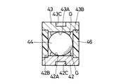
次に、図9ないし図14は本発明の第3の実施の形態を示し、本実施の形態の特徴は、筒状カバーの内周側に、球体をガイドするためのガイド筒を設ける構成としたことにある。なお、本実施の形態では、第1の実施の形態と同一の構成要素に同一の符号を付し、その説明を省略するものとする。
【0065】
41は本実施の形態に係るスラスト荷重支持体で、該スラスト荷重支持体41は、後述のケーシング側受承体42、スクロール側受承体43、球体44、筒状カバー45およびガイド筒46によって構成されている。
【0066】
42は本実施の形態に用いるケーシング側受承体で、該ケーシング側受承体42は、表面側に設けられた平坦面42Aと、該平坦面42Aの外周側に設けられたガイド筒取付段部42Bと、裏面側に設けられたピン穴42Cとを有している。
【0067】
43は本実施の形態に用いるスクロール側受承体で、該スクロール側受承体43は、表面側に設けられた平坦面43Aと、該平坦面43Aの外周側に設けられたガイド筒取付段部43Bと、裏面側に設けられたピン穴43Cとを有している。
【0068】
44は本実施の形態に用いる球体で、該球体44は、ケーシング側受承体42、スクロール側受承体43に転動可能に接触すると共に、ガイド筒46にも接触している。
【0069】
45は本実施の形態に用いる筒状カバーで、該筒状カバー45は、例えばシリコン等の弾性樹脂材料、ゴム材料等を用いて円筒状に形成されている。ここで、筒状カバー45は、その内径が球体44の半径よりも大きく形成されている。そして、筒状カバー45は、ケーシング側受承体42の外周側、スクロール側受承体43の外周側にそれぞれ固着して取付けられると共に、ガイド筒46の外周側に固着して取付けられている。
【0070】
46は筒状カバー45の内周側に設けられたガイド部材としてのガイド筒で、該ガイド筒46は、筒状カバー45と同様の材料、例えばシリコン等の弾性樹脂材料、ゴム材料等を用いて円筒状に形成されている。ここで、ガイド筒46は、その内径が球体44とほぼ同径に設定されている。
【0071】
また、ガイド筒46は、軸方向の一端側がケーシング側受承体42のガイド筒取付段部42Bに固着して取付けられ、軸方向の他端側がスクロール側受承体43のガイド筒取付段部43Bに固着して取付けられている。そして、ガイド筒46は球体44に接触することにより、球体44の軌道を一定に保ち、ケーシング側受承体42、スクロール側受承体43に対する球体44の転動位置を規制する構成となっている。
【0072】
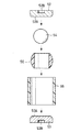
次に、スラスト荷重支持体の製造方法について、図10ないし図14を参照しつつ説明する。
【0073】
まず、図10に示すように、ケーシング側受承体42上に円柱状の内型47を載置すると共に、ケーシング側受承体42の外周側には円筒状をなす第1の外型48を載置する(第1の型載置工程)。
【0074】
次に、内型47と外型48との間の隙間にシリコン等を含有した樹脂材料を流し込み、内型47と外型48を取外すことにより、図11に示すようにケーシング側受承体42のガイド筒取付段部42Bにガイド筒46を一体成形する(ガイド筒成形工程)。
【0075】
次に、図12に示すように、ガイド筒46内にグリースGと一緒に球体44を収容する(球体収容工程)。そして、ガイド筒46の内周側にスクロール側受承体43を嵌合して取付ける(スクロール側受承体取付工程)。
【0076】
次に、図13に示すように、ガイド筒46の外周側に円筒状の第2の外型49を載置する(第2の型載置工程)。次に、ケーシング側受承体42と外型49との間、スクロール側受承体43と外型49との間、ガイド筒46と外型49との間の隙間にシリコン等を含有した樹脂材料を流し込む。そして、外型49を取外すことにより、図14に示すように筒状カバー45をケーシング側受承体42の外周側、スクロール側受承体43の外周側、ガイド筒46の外周側に一体成形する(筒状カバー成形工程)。
【0077】
かくして、本実施の形態でも、ガイド筒46により球体44の軌道を一定に保つことができ、第1の実施の形態とほぼ同様の作用効果を得ることができる。
【0078】
特に、本実施の形態では、筒状カバー45とガイド筒46とを同様の材料を用いて形成したので、筒状カバー45の成形時には筒状カバー45とガイド筒46とが相互になじみ、筒状カバー45をガイド筒46の外周側に接着することなく一体成形することができ、接着をした場合のようなはがれの虞れがなくなり、スラスト荷重支持体41の寿命等を高めることができる。
【0079】
次に、図15および図16は本発明の第4の実施の形態を示し、本実施の形態の特徴は、筒状カバーの内周側に、球体をガイドするためのガイド筒を設け、このガイド筒の外形状を球面状に形成したことにある。なお、本実施の形態では、第1の実施の形態と同一の構成要素に同一の符号を付し、その説明を省略するものとする。
【0080】
51は本実施の形態に係るスラスト荷重支持体で、該スラスト荷重支持体51は、後述のケーシング側受承体52、スクロール側受承体53、球体54、筒状カバー55およびガイド筒56によって構成されている。
【0081】
52は本実施の形態に用いるケーシング側受承体で、該ケーシング側受承体52は、表面側が平坦面52Aとなり、裏面側にはピン穴52Bが設けられている。53は本実施の形態に用いるスクロール側受承体で、該スクロール側受承体53は、表面側が平坦面53Aとなり、裏面側にはピン穴53Bが設けられている。
【0082】
54は本実施の形態に用いる球体で、該球体54は、ケーシング側受承体52、スクロール側受承体53に転動可能に接触すると共に、ガイド筒56にも接触している。
【0083】
55は本実施の形態に用いる筒状カバーで、該筒状カバー55は、例えばシリコン等の弾性樹脂材料、ゴム材料等を用いて円筒状に形成されている。ここで、筒状カバー55は、その内径が球体54の半径よりも大きく形成されている。そして、筒状カバー55は、ケーシング側受承体52の外周側、スクロール側受承体53の外周側にそれぞれ固着して取付けられると共に、ガイド筒56の外周側に固着して取付けられている。
【0084】
56は筒状カバー55の内周側に設けられたガイド部材としてのガイド筒で、該ガイド筒56は、筒状カバー55と同様の材料、例えばシリコン等の弾性樹脂材料、ゴム材料等を用いることにより外周形状が球形状をなした筒状体として形成されている。ここで、ガイド筒56は、その内径が球体54とほぼ同径に設定されている。
【0085】
かくして、このように構成される本実施の形態でも、運転時にはガイド筒56により球体54の軌道を一定に保つことができ、第3の実施の形態とほぼ同様の作用効果を得ることができる。
【0086】
なお、第1の実施の形態では、ケーシング側受承体22の裏面側に位置決めピン23を取付けると共に、スクロール側受承体24の裏面側に位置決めピン25を取付ける構成とした場合を例に挙げて説明した。一方、例えば図17に示す参考例では、ケーシング側受承体22′の裏面側に突起22A′を突設すると共に、スクロール側受承体24′の裏面側にも突起24A′を突設する構成としている。
【0087】
また、前記第1の実施の形態では、球体26を潤滑する潤滑手段としてグリースを用いる場合を例に挙げて説明したが、本発明はこれに限ることなく、潤滑手段として、例えば潤滑油を用いる構成としてもよい。このことは第2,第3,第4の実施の形態についても同様である。
【0088】
また、前記第3の実施の形態では、筒状カバー45とガイド筒46を同一の材料を用いて形成する場合を例に挙げて説明したが、本発明はこれに限ることなく、筒状カバー45とガイド筒46を互いに異なる材料を用いて形成してもよい。このことは第4の実施の形態についても同様である。
【0089】
さらに、各実施の形態ではスクロール式流体機械としてスクロール式空気圧縮機を例に挙げて説明したが、本発明はこれに限ることなく、例えば真空ポンプ、冷媒圧縮機等にも広く適用できる。
【0090】
【発明の効果】
以上詳述した通り、請求項1の発明によれば、スラスト荷重支持体は、ケーシングに取付けられるケーシング側受承体と、旋回スクロールの背面側に取付けられるスクロール側受承体と、該スクロール側受承体とケーシング側受承体とに転動可能に接触する球体と、軸方向の一端側が前記ケーシング側受承体の外周側に固着され、軸方向の他端側が前記スクロール側受承体の外周側に固着され、内部に前記球体を収容する筒状カバーとによって構成したので、筒状カバー内に外部から塵埃等が侵入する不具合を解消することができる。
【0091】
これにより、運転時には球体をケーシング側受承体とスクロール側受承体に対して円滑に転動させることができ、球体により旋回スクロールに作用するスラスト荷重を安定して支持することができ、当該スクロール式流体機械の寿命を延ばし、信頼性等を高めることができる。また、スラスト荷重支持体には従来技術で述べたようなシールを設ける必要がなくなり、シールの摺動面を不要にでき、旋回スクロールを小型化して形成することができる。
また、ケーシング側受承体を位置決めピンを用いてケーシングに取付ける構成としたので、位置決めピンによりケーシング側受承体をケーシングに対し容易に位置決めして取付けることができる。さらに、スクロール側受承体を位置決めピンを用いて旋回スクロールに取付ける構成としたので、位置決めピンによりスクロール側受承体を旋回スクロールに対して容易に位置決めして取付けることができる。従って、ケーシング側受承体、スクロール側受承体の組付時の作業性等を高めることができる。
【0092】
また、請求項2の発明は、ケーシング側受承体はケーシングに対して位置決めし、スクロール側受承体は旋回スクロールに対して位置決めする構成としたので、当該スクロール式流体機械の組立時にはケーシング側受承体をケーシングに対し容易に位置決めして取付けることができると共に、スクロール側受承体を旋回スクロールに対し容易に位置決めして取付けることができ、ケーシング側受承体、スクロール側受承体の組付時の作業性等を高めることができる。
【0093】
また、請求項3の発明は、筒状カバーを弾性を有する材料を用いて形成したので、運転時に筒状カバーを旋回スクロールの旋回動作に追従して弾性変形させることができ、筒状カバーの性能等を高めることができる。
【0094】
さらに、請求項4の発明は、ケーシング側受承体またはスクロール側受承体には球体の軌道を規制する円形の凹窪部を設ける構成としたので、運転時には球体を、ケーシング側受承体またはスクロール側受承体に設けた円形の凹窪部に沿って円滑にガイドすることができ、球体の動きを安定化させ、スラスト荷重支持体の性能、信頼性等を高めることができる。
【0095】
さらに、請求項5の発明は、筒状カバーの内周側にはケーシング側受承体およびスクロール側受承体に対する球体の転動位置を規制するためのガイド部材を配置する構成としたので、運転時には筒状カバーの内周側に配置したガイド部材により球体を円滑にガイドすることができ、球体の動きを安定化させ、スラスト荷重支持体の性能、信頼性等を高めることができる。
【0096】
一方、請求項6の発明は、ガイド部材は筒状カバーと同一の材料を用いて形成したので、筒状カバーの成形時に筒状カバーとガイド部材との接触部が相互になじみ、筒状カバーをガイド部材に一体的に接合することができ、接着をした場合のようなはがれの虞れがなくなり、スラスト荷重支持体の寿命等を高めることができる。
【図面の簡単な説明】
【図1】 本発明の第1の実施の形態によるスクロール式空気圧縮機を示す縦断面図である。
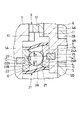
【図2】 自転防止機構、スラスト荷重支持体等を図1中の矢示II−II方向から拡大してみた断面図である。
【図3】 図1中のスラスト荷重支持体等を拡大して示す要部拡大断面図である。
【図4】 第1の実施の形態による型載置工程を示す縦断面図である。
【図5】 第1の実施の形態による筒状カバー成形工程を示す縦断面図である。
【図6】 第1の実施の形態による球体収容工程を示す縦断面図である。
【図7】 第1の実施の形態によるスクロール側受承体取付工程を示す縦断面図である。
【図8】 本発明の第2の実施の形態によるスクロール式空気圧縮機のスラスト荷重支持体等を示す図3と同様の要部断面図である。
【図9】 本発明の第3の実施の形態によるスクロール式空気圧縮機のスラスト荷重支持体等を示す図3と同様の要部断面図である。
【図10】 第3の実施の形態による第1の型載置工程を示す縦断面図である。
【図11】 第3の実施の形態によるガイド筒成形工程を示す縦断面図である。
【図12】 第3の実施の形態による球体収容工程およびスクロール側受承体取付工程を示す縦断面図である。
【図13】 第3の実施の形態による第2の型載置工程を示す縦断面図である。
【図14】 第3の実施の形態による筒状カバー成形工程を示す縦断面図である。
【図15】 本発明の第4の実施の形態によるスクロール式空気圧縮機のスラスト荷重支持体等を示す図3と同様の要部断面図である。
【図16】 図15中のスラスト荷重支持体を示す分解図である。
【図17】 本発明の参考例によるスラスト荷重支持体を示す図7と同様の断面図である。
【符号の説明】
1 ケーシング
2 固定スクロール
3 駆動軸
4 旋回スクロール
6 圧縮室
21,31,41,51 スラスト荷重支持体
22,22′,32,42,52 ケーシング側受承体
23,25 位置決めピン
24,24′,33,43,53 スクロール側受承体
22A′,24A′ 突起
26,34,44,54 球体
27,35,45,55 筒状カバー
46,56 ガイド筒(ガイド部材)[0001]
BACKGROUND OF THE INVENTION
The present invention relates to a scroll fluid machine suitable for use in, for example, an air compressor, a vacuum pump, or the like.
[0002]
[Prior art]
In general, a scroll type fluid machine used for a scroll type air compressor or the like includes a casing, a fixed scroll provided in the casing, a drive shaft rotatably provided in the casing, and a tip end side of the drive shaft. And a orbiting scroll which is provided so as to be capable of turning and defines a plurality of compression chambers between the fixed scroll and the fixed scroll.
[0003]
In this type of conventional scroll type fluid machine, the drive shaft is driven to rotate from the outside, and the orbiting scroll is orbited with a fixed eccentric dimension with respect to the fixed scroll, so that the fluid such as air sucked from the suction port can be obtained. Compression is sequentially performed in each compression chamber defined between the fixed scroll and the orbiting scroll, and the compressed fluid is discharged outward from the discharge port.
[0004]
Further, some scroll type fluid machines include a thrust load support provided between a casing and the back of the orbiting scroll to support a thrust load acting on the orbiting scroll (for example, Japanese Patent Laid-Open No. 2000-87883). Gazette, JP-A-11-280671, etc.).
[0005]
And this thrust load support body is comprised by the spherical body accommodation case fixed to the casing, and the spherical body which is accommodated in this spherical body accommodation case, and contacts the casing and the back surface of a turning scroll so that rolling is possible.
[0006]
In this prior art, the sphere in the sphere housing case is rolled between the casing and the orbiting scroll according to the orbiting operation of the orbiting scroll, and the thrust load acting on the orbiting scroll is supported by the sphere. It has become.
[0007]
[Problems to be solved by the invention]
By the way, in the scroll type fluid machine according to the above-described prior art, the sphere housing case is provided on the casing side, and the seal provided at the tip of the sphere housing case is slid on the orbiting scroll with respect to the back surface of the orbiting scroll. It is configured.
[0008]
For this reason, there is a problem that a slight gap is generated between the orbiting scroll and the sliding surface of the seal due to a processing error or the like, and dust enters through this gap. In addition, when a part of the grease becomes liquid as the temperature rises, the grease may leak to the outside through the gap, which makes it difficult to completely prevent the grease from leaking.
[0009]
In addition, since the seal member provided on the spherical housing cylinder is configured to be in sliding contact with the back side of the orbiting scroll, the orbiting scroll must be provided with a sliding surface of the seal member, and the orbiting scroll is formed in a larger size. There is a problem that it must be done.
[0010]
The present invention has been made in view of the above-described problems of the prior art, and an object of the present invention is to infiltrate dust or the like from the outside into the sphere constituting the thrust load support body, or to leak grease that lubricates the sphere to the outside. It is an object of the present invention to provide a scroll fluid machine that can prevent the turning of the orbiting scroll and reduce the size of the orbiting scroll.
[0011]
[Means for Solving the Problems]
In order to solve the above-described problem, a scroll fluid machine according to the present invention is provided., Pin holes were providedA casing, a fixed scroll provided in the casing, a drive shaft rotatably provided in the casing,Has a pin hole on the back side,The orbiting scroll provided at the front end side of the drive shaft so as to be orbitable and defining a plurality of compression chambers between the fixed scroll and the casing and the rear surface of the orbiting scroll provided on the orbiting scroll. And a thrust load support for supporting the thrust load to be generated.
[0012]
And the characteristic of the structure which invention of Claim 1 employ | adopts is the said thrust load support body,Pin holes are provided and using positioning pinsThe casingPin hole provided inA casing side receiver attached toPin holes are provided and using positioning pinsThe orbiting scrollPin hole provided inA scroll-side receiving body attached to the scroll-side receiving body, a sphere that contacts the scroll-side receiving body and the casing-side receiving body in a rollable manner, and the one end side in the axial direction is contained in the casing-side receiving. There exists in having comprised with the cylindrical cover fixed to the outer peripheral side of the support body, and the other end side of the axial direction being fixed to the outer peripheral side of the said scroll side receiving body.
[0013]
With this configuration, there is no gap between the cylindrical cover and the casing-side receiving body and between the cylindrical cover and the scroll-side receiving body, and dust and the like enter the cylindrical cover from the outside. Trouble can be solved. Thus, during operation, the sphere can be smoothly rolled with respect to the casing side receiving body and the scroll side receiving body, and the thrust load acting on the orbiting scroll can be stably supported by the sphere.
Further, since the casing side receiving body is attached to the casing using the positioning pins, the casing side receiving body can be easily positioned and attached to the casing by the positioning pins. Furthermore, since the scroll-side receiving body is attached to the orbiting scroll using the positioning pins, the scroll-side receiving body can be easily positioned and attached to the orbiting scroll using the positioning pins. For this reason, the workability | operativity etc. at the time of the assembly | attachment of a casing side receiving body and a scroll side receiving body can be improved.
[0014]
The invention according to
[0015]
With this configuration, the casing-side receiving body can be positioned and attached to the casing when the scroll fluid machine is assembled. In addition, the scroll-side receiving body can be positioned and attached to the orbiting scroll.
[0016]
In the invention of
[0017]
Further, the invention according to
[0018]
Further, in the invention of
[0019]
On the other hand, in the invention of
[0020]
DETAILED DESCRIPTION OF THE INVENTION
Hereinafter, a scroll type air compressor will be described as an example of a scroll type fluid machine according to an embodiment of the present invention, and will be described in detail with reference to the accompanying drawings.
[0021]
1 to 7 show a first embodiment of the present invention. Reference numeral 1 denotes a bottomed cylindrical casing which forms an outer frame of a scroll type fluid machine. The casing 1 has an
[0022]
[0023]
A
[0024]
[0025]
The
[0026]
[0027]
The
[0028]
.. Are four thrust load supports provided between the casing 1 and the
[0029]
[0030]
Further, the casing
[0031]
Further, as shown in FIG. 3, the casing-
[0032]
[0033]
Further, the scroll
[0034]
Further, as shown in FIG. 3, the scroll-
[0035]
[0036]
Here, the
[0037]
[0038]
Therefore, the space between the
[0039]
Here, the inner diameter of the
[0040]
The scroll type air compressor according to the present embodiment has the above-described configuration. Next, the operation of the scroll type air compressor will be described.
[0041]
First, when the
[0042]
At this time, the
[0043]
Next, a method for manufacturing a thrust load support will be described with reference to FIGS.
[0044]
First, as shown in FIG. 4, a cylindrical
[0045]
Next, a resin material containing silicon or the like is poured into the gap between the
[0046]
Next, as shown in FIG. 6, the
[0047]
Thus, in the present embodiment, the space between the casing-
[0048]
For this reason, the
[0049]
Further, the
[0050]
Further, since the casing-
[0051]
Further, since the trajectory of the
[0052]
Furthermore, since the
[0053]
On the other hand, since the casing
[0054]
Further, since the scroll-
[0055]
Next, FIG. 8 shows a second embodiment of the present invention. The feature of this embodiment is that the entire surface of the casing side receiving body and the scroll side receiving body is formed as a flat surface, and a sphere is formed. The configuration is such that it is brought into contact with the cylindrical cover. In the present embodiment, the same components as those in the first embodiment are denoted by the same reference numerals, and the description thereof is omitted.
[0056]
31 is a thrust load support according to the present embodiment. The
[0057]
[0058]
[0059]
[0060]
[0061]
However, the
[0062]
Thus, in the present embodiment configured as described above, it is possible to obtain substantially the same operational effects as those of the first embodiment.
[0063]
In particular, in the present embodiment, by bringing the
[0064]
Next, FIGS. 9 to 14 show a third embodiment of the present invention. The feature of the present embodiment is that a guide cylinder for guiding a sphere is provided on the inner peripheral side of the cylindrical cover. It is to have done. In the present embodiment, the same components as those in the first embodiment are denoted by the same reference numerals, and the description thereof is omitted.
[0065]
41 is a thrust load support according to the present embodiment. The
[0066]
[0067]
[0068]
[0069]
[0070]
[0071]
The
[0072]
Next, a method for manufacturing a thrust load support will be described with reference to FIGS.
[0073]
First, as shown in FIG. 10, a cylindrical
[0074]
Next, a resin material containing silicon or the like is poured into the gap between the
[0075]
Next, as shown in FIG. 12, the
[0076]
Next, as shown in FIG. 13, a cylindrical second
[0077]
Thus, also in the present embodiment, the orbit of the
[0078]
In particular, in the present embodiment, since the
[0079]
Next, FIGS. 15 and 16 show a fourth embodiment of the present invention. The feature of this embodiment is that a guide cylinder for guiding a sphere is provided on the inner peripheral side of the cylindrical cover. That is, the outer shape of the guide tube is formed in a spherical shape. In the present embodiment, the same components as those in the first embodiment are denoted by the same reference numerals, and the description thereof is omitted.
[0080]
[0081]
[0082]
[0083]
[0084]
[0085]
Thus, also in the present embodiment configured in this way, the trajectory of the
[0086]
In the first embodiment, the
[0087]
In the first embodiment, the case where grease is used as the lubricating means for lubricating the
[0088]
In the third embodiment, the case where the
[0089]
Furthermore, in each embodiment, the scroll type air compressor has been described as an example of the scroll type fluid machine. However, the present invention is not limited to this, and can be widely applied to, for example, a vacuum pump, a refrigerant compressor, and the like.
[0090]
【The invention's effect】
As described above in detail, according to the first aspect of the present invention, the thrust load support body includes the casing side receiving body attached to the casing, the scroll side receiving body attached to the back side of the orbiting scroll, and the scroll side. A spherical body that is slidably contacted with the receiving body and the casing side receiving body, and one end side in the axial direction is the casing side receiving body.Outer peripheral sideInFastened,The other end side in the axial direction is the scroll side receiving body.Outer peripheral sideInFastened,Since it is configured by the cylindrical cover that accommodates the sphere inside, it is possible to solve the problem of dust and the like entering the cylindrical cover from the outside.
[0091]
This,During operation, the sphere can be smoothly rolled with respect to the casing side receiving body and the scroll side receiving body, and the thrust load acting on the orbiting scroll can be stably supported by the sphere. The life of the machine can be extended and the reliability and the like can be improved. Further, it is not necessary to provide a seal as described in the prior art on the thrust load support body, the sliding surface of the seal can be eliminated, and the orbiting scroll can be formed in a small size.
Further, since the casing side receiving body is attached to the casing using the positioning pins, the casing side receiving body can be easily positioned and attached to the casing by the positioning pins. Furthermore, since the scroll-side receiving body is attached to the orbiting scroll using the positioning pins, the scroll-side receiving body can be easily positioned and attached to the orbiting scroll using the positioning pins. Therefore, workability and the like when assembling the casing side receiving body and the scroll side receiving body can be improved.
[0092]
In the invention of
[0093]
In the invention of
[0094]
Furthermore, the invention of
[0095]
Furthermore, since the invention of
[0096]
On the other hand, since the guide member is formed using the same material as that of the cylindrical cover, the contact portion between the cylindrical cover and the guide member becomes compatible with each other when the cylindrical cover is formed. Can be integrally bonded to the guide member, and there is no risk of peeling as in the case of bonding, and the life of the thrust load support can be increased.
[Brief description of the drawings]
FIG. 1 is a longitudinal sectional view showing a scroll type air compressor according to a first embodiment of the present invention.
FIG. 2 is a cross-sectional view of an anti-rotation mechanism, a thrust load support, and the like, enlarged from the direction of arrows II-II in FIG.
FIG. 3 is an enlarged cross-sectional view of a main part showing the thrust load support and the like in FIG. 1 in an enlarged manner.
FIG. 4 is a longitudinal sectional view showing a mold placing process according to the first embodiment.
FIG. 5 is a longitudinal sectional view showing a cylindrical cover forming step according to the first embodiment.
FIG. 6 is a longitudinal sectional view showing a sphere housing process according to the first embodiment.
FIG. 7 is a longitudinal sectional view showing a scroll side receiving body attaching step according to the first embodiment.
8 is a sectional view similar to FIG. 3 showing a thrust load support body and the like of a scroll type air compressor according to a second embodiment of the present invention.
FIG. 9 is a sectional view similar to FIG. 3 showing a thrust load support and the like of a scroll type air compressor according to a third embodiment of the present invention.
FIG. 10 is a longitudinal sectional view showing a first mold placing step according to a third embodiment.
FIG. 11 is a longitudinal sectional view showing a guide tube forming process according to a third embodiment.
FIG. 12 is a longitudinal sectional view showing a sphere housing process and a scroll side receiving body attaching process according to a third embodiment.
FIG. 13 is a longitudinal sectional view showing a second mold placing step according to the third embodiment.
FIG. 14 is a longitudinal sectional view showing a cylindrical cover forming step according to the third embodiment.
FIG. 15 is a sectional view similar to FIG. 3 showing a thrust load support and the like of a scroll type air compressor according to a fourth embodiment of the present invention.
16 is an exploded view showing a thrust load support in FIG. 15. FIG.
FIG. 17 shows the present invention.referenceIt is sectional drawing similar to FIG. 7 which shows the thrust load support body by an example.
[Explanation of symbols]
1 casing
2 Fixed scroll
3 Drive shaft
4 Orbiting scroll
6 Compression chamber
21, 31, 41, 51 Thrust load support
22, 22 ', 32, 42, 52 Casing side receptacle
23, 25 Positioning pin
24, 24 ', 33, 43, 53 Scroll side receptacle
22A ', 24A' protrusion
26, 34, 44, 54 Sphere
27, 35, 45, 55 Cylindrical cover
46, 56 Guide tube (guide member)
Claims (6)
前記スラスト荷重支持体は、ピン穴が設けられ、位置決めピンを用いて前記ケーシングに設けられたピン穴に取付けられるケーシング側受承体と、ピン穴が設けられ、位置決めピンを用いて前記旋回スクロールに設けられたピン穴に取付けられるスクロール側受承体と、該スクロール側受承体と前記ケーシング側受承体とに転動可能に接触する球体と、内部に前記球体を収容し軸方向の一端側が前記ケーシング側受承体の外周側に固着され、軸方向の他端側が前記スクロール側受承体の外周側に固着された筒状カバーとによって構成したスクロール式流体機械。 A casing provided with a pin hole , a fixed scroll provided in the casing, a drive shaft rotatably provided in the casing, and a pin hole on the back side, and can be turned to the tip side of the drive shaft A thrust scroll that defines a plurality of compression chambers between the fixed scroll and the fixed scroll; and a thrust load support that is provided between the casing and the back of the orbiting scroll and supports a thrust load acting on the orbiting scroll. for example Bei and body,
The thrust load support body is provided with a pin hole , a casing side receiving body attached to the pin hole provided in the casing using a positioning pin , a pin hole is provided, and the orbiting scroll is provided with a positioning pin. A scroll-side receiving body that is attached to a pin hole provided in the inner surface, a sphere that is slidably in contact with the scroll-side receiving body and the casing-side receiving body, one end is fixed to the outer peripheral side of the casing side nest member, scroll type fluid machine to which the other end side in the axial direction is constituted by the anchored cylindrical cover on the outer peripheral side of the scroll-side nest member.
Priority Applications (1)
| Application Number | Priority Date | Filing Date | Title |
|---|---|---|---|
| JP2001260011A JP4732637B2 (en) | 2001-08-29 | 2001-08-29 | Scroll type fluid machine |
Applications Claiming Priority (1)
| Application Number | Priority Date | Filing Date | Title |
|---|---|---|---|
| JP2001260011A JP4732637B2 (en) | 2001-08-29 | 2001-08-29 | Scroll type fluid machine |
Publications (2)
| Publication Number | Publication Date |
|---|---|
| JP2003065259A JP2003065259A (en) | 2003-03-05 |
| JP4732637B2 true JP4732637B2 (en) | 2011-07-27 |
Family
ID=19087279
Family Applications (1)
| Application Number | Title | Priority Date | Filing Date |
|---|---|---|---|
| JP2001260011A Expired - Fee Related JP4732637B2 (en) | 2001-08-29 | 2001-08-29 | Scroll type fluid machine |
Country Status (1)
| Country | Link |
|---|---|
| JP (1) | JP4732637B2 (en) |
Families Citing this family (5)
| Publication number | Priority date | Publication date | Assignee | Title |
|---|---|---|---|---|
| JP2005337189A (en) | 2004-05-31 | 2005-12-08 | Anest Iwata Corp | Method for manufacturing revolving scroll of scroll fluid machine |
| DE102007004716A1 (en) * | 2007-01-31 | 2008-08-07 | Schaeffler Kg | Bearing arrangement, has axially running grooves for winding set of rolling elements that are designed as balls, so that axial forces are transferred over balls, and radial tracks for winding another set of rolling elements |
| JP5150206B2 (en) * | 2007-10-31 | 2013-02-20 | 株式会社日立産機システム | Scroll type fluid machine |
| JP5380013B2 (en) | 2008-07-31 | 2014-01-08 | 株式会社日立産機システム | Scroll type fluid machine |
| JP6842385B2 (en) * | 2017-08-25 | 2021-03-17 | 三菱重工サーマルシステムズ株式会社 | Scroll compressor |
Family Cites Families (9)
| Publication number | Priority date | Publication date | Assignee | Title |
|---|---|---|---|---|
| JPS5859392A (en) * | 1981-10-05 | 1983-04-08 | Nippon Soken Inc | Scroll type pump |
| JPS6254294A (en) * | 1985-09-02 | 1987-03-09 | ヤマハ株式会社 | Transposition data setter for keyed instrument |
| US4831275A (en) * | 1986-11-12 | 1989-05-16 | Quential, Inc. | Method and means for self-referencing and self-focusing a bar-code reader |
| JP2796811B2 (en) * | 1988-10-20 | 1998-09-10 | トキコ株式会社 | Scroll type fluid machine |
| JP3053551B2 (en) * | 1995-08-03 | 2000-06-19 | サンデン株式会社 | Ball coupling |
| JPH0953575A (en) * | 1995-08-15 | 1997-02-25 | Tokico Ltd | Scroll type fluid machinery |
| JPH1047263A (en) * | 1996-07-29 | 1998-02-17 | Tokico Ltd | Scroll type fluid machine |
| JPH10159988A (en) * | 1996-11-29 | 1998-06-16 | Musashi Seimitsu Ind Co Ltd | Dust cover |
| JP3663849B2 (en) * | 1997-08-21 | 2005-06-22 | Nok株式会社 | Dust cover |
-
2001
- 2001-08-29 JP JP2001260011A patent/JP4732637B2/en not_active Expired - Fee Related
Also Published As
| Publication number | Publication date |
|---|---|
| JP2003065259A (en) | 2003-03-05 |
Similar Documents
| Publication | Publication Date | Title |
|---|---|---|
| JP7063299B2 (en) | Scroll compressor | |
| US8206138B2 (en) | Scroll fluid machine with ball coupling rotation prevention mechanism | |
| JP4732637B2 (en) | Scroll type fluid machine | |
| JP2019178678A (en) | Scroll type motor-driven compressor | |
| JPH02248675A (en) | scroll fluid machine | |
| JPH09250464A (en) | Auto-rotation prevension mechanism used for scroll type compressor | |
| JP2000297757A (en) | Compressor | |
| JPH1193864A (en) | Scroll type fluid machine | |
| JP2004124735A (en) | Scroll type fluid machine | |
| JP2005133693A (en) | Scroll fluid-machinery wherein gap is easily adjustable | |
| JPH11280669A (en) | Scroll type fluid machine | |
| JP2000220587A (en) | Scroll type compressor | |
| JP2000087880A (en) | Scroll type fluid machine | |
| JP2553043Y2 (en) | Rotary shaft support structure for scroll compressor | |
| JPH0494483A (en) | Scroll type compressor | |
| JP4917424B2 (en) | Scroll type fluid machine | |
| JP3595035B2 (en) | Whole rotary scroll fluid machine with scroll plate adjustment mechanism | |
| JP2002257057A (en) | Scroll type fluid machine | |
| JP2001012369A (en) | Compressor | |
| JPH051503A (en) | Scroll type fluid machinery | |
| JPS5941035B2 (en) | positive displacement fluid compression device | |
| JP2004340255A (en) | Bearing device | |
| JPH09268984A (en) | Scroll type fluid machine | |
| JP3053552B2 (en) | Ball coupling | |
| JP4825467B2 (en) | Scroll type fluid machine and manufacturing method thereof |
Legal Events
| Date | Code | Title | Description |
|---|---|---|---|
| A711 | Notification of change in applicant |
Free format text: JAPANESE INTERMEDIATE CODE: A712 Effective date: 20041129 |
|
| A621 | Written request for application examination |
Free format text: JAPANESE INTERMEDIATE CODE: A621 Effective date: 20080729 |
|
| A521 | Request for written amendment filed |
Free format text: JAPANESE INTERMEDIATE CODE: A821 Effective date: 20080731 |
|
| A977 | Report on retrieval |
Free format text: JAPANESE INTERMEDIATE CODE: A971007 Effective date: 20100528 |
|
| A131 | Notification of reasons for refusal |
Free format text: JAPANESE INTERMEDIATE CODE: A131 Effective date: 20100608 |
|
| A521 | Request for written amendment filed |
Free format text: JAPANESE INTERMEDIATE CODE: A523 Effective date: 20100728 |
|
| A02 | Decision of refusal |
Free format text: JAPANESE INTERMEDIATE CODE: A02 Effective date: 20101109 |
|
| A521 | Request for written amendment filed |
Free format text: JAPANESE INTERMEDIATE CODE: A523 Effective date: 20110204 |
|
| A911 | Transfer to examiner for re-examination before appeal (zenchi) |
Free format text: JAPANESE INTERMEDIATE CODE: A911 Effective date: 20110209 |
|
| A711 | Notification of change in applicant |
Free format text: JAPANESE INTERMEDIATE CODE: A712 Effective date: 20110310 |
|
| RD02 | Notification of acceptance of power of attorney |
Free format text: JAPANESE INTERMEDIATE CODE: A7422 Effective date: 20110311 |
|
| RD04 | Notification of resignation of power of attorney |
Free format text: JAPANESE INTERMEDIATE CODE: A7424 Effective date: 20110331 |
|
| TRDD | Decision of grant or rejection written | ||
| A01 | Written decision to grant a patent or to grant a registration (utility model) |
Free format text: JAPANESE INTERMEDIATE CODE: A01 Effective date: 20110419 |
|
| A01 | Written decision to grant a patent or to grant a registration (utility model) |
Free format text: JAPANESE INTERMEDIATE CODE: A01 |
|
| A61 | First payment of annual fees (during grant procedure) |
Free format text: JAPANESE INTERMEDIATE CODE: A61 Effective date: 20110421 |
|
| FPAY | Renewal fee payment (event date is renewal date of database) |
Free format text: PAYMENT UNTIL: 20140428 Year of fee payment: 3 |
|
| R150 | Certificate of patent or registration of utility model |
Free format text: JAPANESE INTERMEDIATE CODE: R150 |
|
| LAPS | Cancellation because of no payment of annual fees |