JP4732176B2 - Insulation panel and method of installing the insulation panel - Google Patents
Insulation panel and method of installing the insulation panel Download PDFInfo
- Publication number
- JP4732176B2 JP4732176B2 JP2006021704A JP2006021704A JP4732176B2 JP 4732176 B2 JP4732176 B2 JP 4732176B2 JP 2006021704 A JP2006021704 A JP 2006021704A JP 2006021704 A JP2006021704 A JP 2006021704A JP 4732176 B2 JP4732176 B2 JP 4732176B2
- Authority
- JP
- Japan
- Prior art keywords
- heat insulating
- panel
- heat
- heat insulation
- net
- Prior art date
- Legal status (The legal status is an assumption and is not a legal conclusion. Google has not performed a legal analysis and makes no representation as to the accuracy of the status listed.)
- Active
Links
Images


Landscapes
- Building Environments (AREA)
- Panels For Use In Building Construction (AREA)
Description
本発明は、断熱パネルと断熱パネルを建築物の壁面に取付ける取付け方法に係り、特に、壁面に取付けられた隣接する断熱パネル間に段差が生じたり、壁施工時のセメントペーストが断熱パネルの表面に付着した際に、断熱パネルを損傷させることなく、容易に段差を解消し、あるいはセメントペーストを取り除くことができる断熱パネルと、断熱パネルの取付け方法に関するものである。 The present invention relates to a heat insulating panel and a mounting method for mounting the heat insulating panel on a wall surface of a building. In particular, a step is generated between adjacent heat insulating panels mounted on the wall surface, or cement paste at the time of wall construction is a surface of the heat insulating panel. The present invention relates to a heat insulating panel that can easily eliminate a step or remove a cement paste without damaging the heat insulating panel, and a method for attaching the heat insulating panel.
建築物の壁面に断熱パネルを取付け、該断熱パネルの表面にモルタル等の湿式建材を施工する場合には、断熱パネルの表面に、メタルラスやワイヤーラスといったラスが予め固着されてなる断熱パネルが適用されることがある。ラスを断熱パネル表面に固着しておくことにより、湿式建材を塗布する際の、断熱パネルと湿式建材との付着性を高めることができる。 When a thermal insulation panel is attached to the wall of a building and wet construction materials such as mortar are applied to the surface of the thermal insulation panel, a thermal insulation panel in which a lath such as a metal lath or wire lath is fixed in advance to the surface of the thermal insulation panel is applied May be. By adhering the lath to the surface of the heat insulating panel, the adhesion between the heat insulating panel and the wet building material when applying the wet building material can be enhanced.
上記形態の断熱パネルに関する従来の技術として、例えば特許文献1,2を挙げることができる。特許文献1に開示の技術は、型枠兼用の断熱パネルに関するものである。この断熱パネルは、ポリスチレン系樹脂フォームの少なくとも片面に網材が固着されており、この網材は、化学繊維系メッシュないしは金属製メッシュからなり、樹脂フォームと網材とが、縫い付けや接着剤、熱ラミネーションによって固着されるものである。かかる仕様の網材をかかる固着形態によって樹脂フォームに固着させることにより、型枠の曲げ強度や耐衝撃性を高めることができ、運搬性や作業能率を向上させることができるというものである。
For example,
一方、特許文献2に開示の技術は、発泡樹脂ボードの表面にラスが一体に融着されてなる施工用発泡樹脂ボードに関するものである。発泡樹脂ボードにラスが融着一体化していることで、ラスが容易に剥離することがなく、ボード自体の強度も高めることができる。さらに、ボードを発泡樹脂から成形することにより、断熱性や防水性を高めることができ、建築物の壁や床などの施工に際し、別途の断熱材や防水シートを施工する必要がなくなり、作業効率の向上を図ることができるというものである。
On the other hand, the technique disclosed in
特許文献1に開示の型枠兼用の断熱パネル、および特許文献2に開示の施工用発泡樹脂ボードは、いずれも樹脂フォームないしは発泡樹脂ボードなどのパネルに対し、網材ないしはラスが強固に一体に固着されている。このような形態の断熱パネルを適用した場合には、断熱パネルの取付け方法が双方の断熱パネルで異なるものの、それぞれに固有の問題が生じ得る。
The heat insulating panel also used as a formwork disclosed in
まず、建築物の壁を施工するに際し、型枠兼用の断熱パネルとして特許文献1に開示の断熱パネルを適用する場合の問題点として、セメントペースト(いわゆるノロ)が隣接する断熱パネル間を通って断熱パネルの仕上げ面側(壁面と反対側の表面)へ流出した際の補修の困難性が挙げられる。すなわち、樹脂フォームに網材が強固に固着されているため、樹脂フォームを損傷させずに網材のみを剥がすことができない。したがって、網材に絡みついた、仕上げに不要なセメントペーストを除去することができず、逆に除去するために網材を樹脂フォームから剥がそうとすると、網材による剥離力によって樹脂フォームが損傷することは必至である。
First, when constructing a wall of a building, as a problem when applying the heat insulating panel disclosed in
一方、壁が施工された後に、その表面に特許文献2に開示の発泡樹脂ボードを貼り付ける場合には、施工誤差によってできた壁面の不陸により、隣接する発泡樹脂ボード間で段差が生じる可能性がある。さらには、発泡樹脂ボードを壁面に貼り付けるための接着剤が不均一に塗布されることにより、同様の段差が生じてしまう。この場合、発泡樹脂ボードとラスが強固に固着されていることから、ラスを剥がしてボード表面を削り、段差を解消するといった補修はできず、したがって、段差の窪み側のボード表面には、モルタルなどの表面仕上げ材の厚みを相対的に厚く塗布せざるを得ない。表面仕上げ材の厚みが厚くなったボードには、その分の表面仕上げ材の重量が負荷されることとなり、結果として、相対的に大きなせん断力がボードに作用することとなる。また、ラスは一般に表面仕上げ材のクラック防止やボードとの付着性の向上を目的として適用されるものであり、伸縮性に乏しい素材が一般に適用される。これを断熱ボードに固着することにより、該断熱ボードを曲面状の壁面に取付けた場合には、断熱ボードのラス側の面では伸びようとする力がラスによって抑制され、断熱ボードの壁面側に比して大きな圧縮力となる。したがって、ボード内部で歪んだ内部応力が発生することとなり、ボード自体の耐久性が低下するといった問題もある。
On the other hand, when the foamed resin board disclosed in
本発明の断熱パネルおよび断熱パネルの取付け方法は、上記する問題に鑑みてなされたものであり、壁面に取付けられた隣接する断熱パネル間に段差が生じたり、壁施工時のセメントペーストが断熱パネルの表面に付着した際に、容易に段差を解消し、あるいはセメントペーストを取り除くことができ、また、かかる補修の際に断熱パネル(断熱材)を損傷させることのない断熱パネルと、該断熱パネルの取付け方法を提供することを目的としている。 The heat insulating panel and the method for attaching the heat insulating panel of the present invention have been made in view of the above-described problems, and a step is generated between adjacent heat insulating panels attached to the wall surface, or the cement paste at the time of wall construction is the heat insulating panel. A heat insulating panel that can easily eliminate a step or remove cement paste when it adheres to the surface of the steel, and does not damage the heat insulating panel (heat insulating material) during the repair, and the heat insulating panel The purpose is to provide a mounting method.
前記目的を達成すべく、本発明による断熱パネルは、発泡樹脂からなるパネル状の断熱材の一方面に、粘着剤を介して、網材が剥離可能で、かつ再粘着可能に貼着されてなることを特徴とする。 In order to achieve the above-mentioned object, the heat insulating panel according to the present invention is attached to one surface of a panel-like heat insulating material made of foamed resin through a pressure-sensitive adhesive so that the mesh material can be peeled off and can be re-adhered. It is characterized by becoming.
本発明の断熱パネルが適用される建築物は、一般の住宅やビルのほか、上下水道の建屋をはじめとする公共施設など、建築物の全般を対象としており、その構造形態は、木造、鉄骨製(S造)、鉄筋コンクリート製(RC造)、鉄骨鉄筋コンクリート(SRC造)のいずれの形態であってもよい。さらに、この断熱パネルは、内断熱方式、外断熱方式の双方に適用可能である。 The building to which the heat insulation panel of the present invention is applied covers general buildings such as general houses and buildings as well as public facilities such as water and sewage buildings, and its structural form is wooden, steel frame Any form of manufactured (S structure), reinforced concrete (RC structure), and steel-framed reinforced concrete (SRC structure) may be sufficient. Furthermore, this heat insulation panel can be applied to both the inner heat insulation method and the outer heat insulation method.
断熱材の素材としての発泡樹脂材は、ポリスチレン発泡体、ポリエチレン発泡体、ポリプロピレン発泡体、硬質ウレタン発泡体、フェノール発泡体、イソシアネート発泡体、エポキシ発泡体などを挙げることができる。この断熱材は、押出し発泡成形法や発泡ビーズ型内発泡成形法などによって成形することができる。また、その密度は、必要断熱性能に応じて適宜の値に設定できるが、例えば、10〜100kg/m3程度が好ましい。さらに、断熱パネルの厚みや平面寸法は特に限定されるものではなく、設計仕様や施工環境等に応じて適宜に選定し得るものであるが、例えば、平面視が矩形の形態や、隅角部に適用される形態としては断面視がL字状の形態、さらには全体が湾曲した形態などが挙げられる。 Examples of the foamed resin material as the material for the heat insulating material include polystyrene foam, polyethylene foam, polypropylene foam, rigid urethane foam, phenol foam, isocyanate foam, and epoxy foam. This heat insulating material can be formed by an extrusion foam molding method, a foam bead-in-mold foam molding method, or the like. Moreover, although the density can be set to a suitable value according to required heat insulation performance, about 10-100 kg / m < 3 > is preferable, for example. Furthermore, the thickness and plane dimensions of the heat insulation panel are not particularly limited, and can be appropriately selected according to design specifications, construction environment, etc. Examples of the configuration applied to the shape include an L-shaped cross-sectional view and a curved shape as a whole.
パネル状の断熱材の一方面には、粘着剤を介して網材が貼着されることにより、本発明の断熱パネルが形成される。ここで、網材は、ガラス繊維、金属繊維、合成樹脂繊維などから成形でき、耐アルカリ性の繊維材ないしは耐アルカリ処理を表面に施した繊維材から成形するのが好ましい。また、かかる繊維材からなる経糸と緯糸とを絡ませながら編む、いわゆるからみ織りによって網材を成形するのが好ましい。からみ織りとすることで、目ずれの起き難い網材を形成することができる。また、網材を断熱材に貼着することで、断熱パネルと湿式建材との付着性を高めることができ、さらには、湿式建材のひび割れを抑制することができる。 A heat insulating panel of the present invention is formed on one surface of the panel-like heat insulating material by attaching a netting material via an adhesive. Here, the netting material can be formed from glass fiber, metal fiber, synthetic resin fiber or the like, and is preferably formed from an alkali-resistant fiber material or a fiber material subjected to an alkali-proof treatment on the surface. Further, it is preferable to form a net material by so-called leno weaving, in which warps and wefts made of such a fiber material are knitted together. By entangled weave, it is possible to form a net material that is less prone to misalignment. Moreover, the adhesion of a heat insulation panel and wet building materials can be improved by sticking a net | network material to a heat insulating material, Furthermore, the crack of wet building materials can be suppressed.
上記の網材の一方面には、1ないし複数回剥がし、その都度断熱材表面に粘着させることのできる適宜の粘着剤を予め塗布ないしは貼り付けておくのが望ましい。粘着剤としては、ゴム系、アクリル樹脂系などの素材で、溶剤型、エマルジョン型、ホットメルト型、反応型などの粘着剤を使用することができる。このような粘着剤を介して発泡樹脂からなるパネル状の断熱材と網材とを粘着させることにより、本発明の断熱パネルが形成される。なお、断熱材と網材との粘着強度は、網材の表面に後施工されるモルタル等の湿式建材の重量により、少なくとも網材が断熱材から剥がれない程度の粘着力を要し、さらには、補修時に網材を断熱材から剥がす際に、作業員が剥がし易い程度の粘着力を備えていることが望ましい。 It is desirable that an appropriate pressure-sensitive adhesive that can be peeled off one or more times and adhered to the surface of the heat insulating material each time is applied or pasted on one side of the above-mentioned net material. As the pressure-sensitive adhesive, rubber-based or acrylic resin-based materials such as solvent-type, emulsion-type, hot-melt type, and reaction-type pressure-sensitive adhesives can be used. The heat insulating panel of the present invention is formed by adhering the panel-like heat insulating material made of foamed resin and the netting material through such an adhesive. In addition, the adhesive strength between the heat insulating material and the netting material requires at least an adhesive strength that prevents the netting material from peeling off from the heat insulating material due to the weight of the wet building material such as mortar to be applied to the surface of the netting material. It is desirable that an operator should have an adhesive strength that can be easily removed when the mesh material is removed from the heat insulating material during repair.
また、網材が貼着される断熱材の一方面は、ニクロムカットやサンダー処理等によって表面を微細な凹凸状に形成しておくことにより、湿式建材との付着面積を増加させ、付着力を高めることができる。さらに、隣接する断熱パネル同士の当接端面は、双方の端面同士が嵌め合い可能な適宜の形態に成形しておくことにより、壁コンクリートを打設した際にセメントペーストが上記の当接端面から漏洩し難くすることができる。 In addition, one side of the heat insulating material to which the netting material is stuck is formed with fine irregularities on the surface by nichrome cutting or sanding, etc., thereby increasing the adhesion area with the wet building material and increasing the adhesion force Can be increased. Furthermore, the contact end surfaces of the adjacent heat insulation panels are formed in an appropriate form in which both end surfaces can be fitted to each other, so that when the wall concrete is placed, the cement paste is removed from the contact end surface. It can be made difficult to leak.
本発明の断熱パネルによれば、建築物の壁面に取付けられた隣接する断熱パネル間において段差が生じた場合でも、断熱材から網材を容易に剥がし、例えば突出した側の断熱材表面を削りながら段差を解消し、削られた断熱材表面に、網材を再度貼着させることができる。また、セメントペーストが断熱パネル間から漏洩し、網材と断熱材との間で硬化した場合でも、網材を剥がしてセメントペーストを削り取り、網材を再度貼着させることができる。断熱材の表面から網材を容易に剥がすことができるため、断熱材を何ら損傷させることなく、断熱材表面の補修を極めて容易におこなうことが可能となる。 According to the heat insulating panel of the present invention, even when a step is generated between adjacent heat insulating panels attached to the wall surface of a building, the net material is easily peeled off from the heat insulating material, for example, the surface of the protruding heat insulating material is shaved. However, the step can be eliminated, and the netting material can be pasted again on the surface of the heat-insulated material. Further, even when the cement paste leaks from between the heat insulating panels and hardens between the net material and the heat insulating material, the net material can be peeled off, the cement paste can be scraped off, and the net material can be pasted again. Since the mesh material can be easily peeled off from the surface of the heat insulating material, the surface of the heat insulating material can be repaired very easily without damaging the heat insulating material.
また、本発明による断熱パネルの好ましい実施の形態は、前記網材が、20〜750gf/20mm幅の剥離強度で前記断熱材に貼着されていることを特徴とする。 Moreover, the preferable embodiment of the heat insulation panel by this invention is characterized by the said net | network material being affixed on the said heat insulating material with the peeling strength of 20-750 gf / 20mm width.
発明者等の後述する剥離試験によれば、(1)網材を断熱材から1度剥離させ、再度粘着させた際の粘着力(剥離強度)と、(2)網材を断熱材から剥離させる際の作業性、の2つの要素から、20mm幅の網材が、20〜750gfの剥離強度にて断熱材に粘着されてなる断熱パネルが、双方の要素を満足する好ましい実施の形態であることが実証された。 According to the peel test described later by the inventors, (1) the adhesive strength (peeling strength) when the mesh material is peeled once from the heat insulating material and again adhered, and (2) the net material is peeled from the heat insulating material. A heat insulating panel in which a 20 mm-wide mesh material is adhered to a heat insulating material with a peel strength of 20 to 750 gf is a preferred embodiment that satisfies both elements. It was proved.
上記試験によれば、20gf/20mm幅未満で網材が断熱材に貼着されている場合には、再粘着が不可能、ないしは、再粘着できたとしてもモルタル等の湿式建材の重量で自然に剥がれてしまうこととなって好ましくない。一方、750gf/20mm幅よりも大きな剥離強度の場合には、作業員が網材を剥がす際に剥がし難く、作業性が低くなるという官能結果となってやはり好ましくない。 According to the above test, when the netting material is less than 20 gf / 20 mm width and adhered to the heat insulating material, re-adhesion is impossible, or even if it can be re-adhered, it is natural due to the weight of wet building materials such as mortar. This is not preferable. On the other hand, when the peel strength is larger than 750 gf / 20 mm width, it is difficult to remove the net when the operator peels off the netting material, and this is not preferable because of a sensory result that workability is lowered.
また、本発明による断熱パネルの好ましい実施の形態において、前記粘着剤は、アクリル共重合体水性エマルジョンからなることを特徴とする。 In a preferred embodiment of the heat insulation panel according to the present invention, the pressure-sensitive adhesive is made of an acrylic copolymer aqueous emulsion.
アクリル共重合体水性エマルジョンからなる粘着剤を適用することで、上記する剥離強度範囲の断熱材と網材との粘着を実現でき、かつ、作業性も極めて良好なものとなる。 By applying a pressure-sensitive adhesive made of an acrylic copolymer aqueous emulsion, it is possible to achieve adhesion between the heat insulating material and the netting material in the above-described peel strength range, and the workability is extremely good.
また、本発明による断熱パネルの取付け方法は、発泡樹脂からなるパネル状の断熱材と、その一方面に剥離可能で、かつ再粘着可能に貼着された網材と、からなる断熱パネルを建築物の壁面に取付ける断熱パネルの取付け方法であって、壁を施工するための型枠を設置し、網材が型枠側となるように複数の断熱パネルを所定の型枠面に取付ける第1の工程と、型枠内にコンクリートを打設し、その硬化を待って脱型する第2の工程と、を含み、セメントペーストが断熱材の網材貼着側に漏洩している場合には、いずれか一方または双方の断熱パネルの網材の一部を剥がし、断熱材の表面と網材からセメントペーストを取り除き、剥がした網材を断熱材に再粘着する第3の工程をさらに含むことを特徴とする。 The heat insulating panel mounting method according to the present invention is a construction of a heat insulating panel comprising a panel-shaped heat insulating material made of foamed resin, and a net material that can be peeled and re-adhered to one surface thereof. A method for attaching a heat insulating panel to be attached to a wall surface of an object, wherein a form for installing a wall is installed, and a plurality of heat insulating panels are attached to a predetermined form surface so that the net is on the form side. And when the cement paste leaks to the netting side of the heat insulating material, the second step of placing the concrete in the mold and demolding after waiting for its hardening The method further includes a third step of removing a part of the mesh material of one or both of the heat insulation panels, removing the cement paste from the surface of the heat insulation material and the mesh material, and re-adhering the peeled mesh material to the heat insulation material. It is characterized by.
本発明による断熱パネルの取付け方法は、建築物の壁を施工する際に設置する型枠に予め既述する断熱パネルを取付けておき、型枠内に壁用のコンクリートを打設し、コンクリートの硬化を待って脱型することにより、壁面に断熱パネルが取付けられる取付け方法である。 In the method for attaching a heat insulating panel according to the present invention, a heat insulating panel described above is attached in advance to a formwork to be installed when constructing a wall of a building, and concrete for the wall is placed in the formwork, This is an attachment method in which a heat insulation panel is attached to a wall surface by removing the mold after waiting for curing.
既述するように、コンクリートを打設した際に、隣接する断熱パネル間からはセメントペーストが漏洩する可能性があり、このセメントペーストは、断熱パネルの断熱材と網材の間に浸透した状態で硬化する。この場合、断熱パネルと湿式建材との付着性を高める目的で設けられた網材の網目をセメントペーストが塞いでしまい、付着性が阻害される。さらには、断熱材表面に形成しておいた凹凸面も同様にセメントペーストにて塞がれてしまうこととなる。セメントペーストは、水分の多いセメントからなり、極めて強度(付着強度や圧縮強度)が低いことから、湿式建材を塗布する前に取り除く必要がある。 As described above, when concrete is placed, cement paste may leak from between adjacent thermal insulation panels, and this cement paste penetrates between the thermal insulation material and the mesh material of the thermal insulation panel. Cured with. In this case, the cement paste closes the mesh of the mesh material provided for the purpose of enhancing the adhesion between the heat insulating panel and the wet building material, and the adhesion is hindered. Furthermore, the uneven surface formed on the surface of the heat insulating material is similarly blocked by the cement paste. Cement paste is made of cement with a lot of water and has extremely low strength (adhesion strength and compressive strength), so it must be removed before applying wet building materials.
そこで、セメントペーストが漏洩/硬化している場合には、補修の必要な箇所の網材を断熱材表面から剥がし、セメントペーストをサンダー処理やはつり処理等にて取り除き、剥がした網材を再度断熱材表面に貼り付けることにより、後施工される湿式建材と断熱パネルとの間の所望の付着力(再粘着時に必要となる最低限以上の付着力)を確保することが可能となる。 Therefore, if the cement paste is leaked / hardened, remove the mesh material where repair is required from the surface of the heat insulating material, remove the cement paste by sanding or suspending, etc., and insulate the removed mesh material again. By sticking on the material surface, it is possible to ensure a desired adhesion force between the wet building material to be applied later and the heat insulating panel (minimum adhesion force required at the time of re-adhesion).
さらに、本発明による断熱パネルの取付け方法の他の実施の形態は、発泡樹脂からなるパネル状の断熱材と、その一方面に剥離可能で、かつ再粘着可能に貼着された網材と、からなる断熱パネルを建築物の壁面に取付ける断熱パネルの取付け方法であって、建築物の壁を施工する第1の工程と、壁面に複数の断熱パネルを貼着する第2の工程と、を含み、隣接する断熱パネルの間に段差が生じた場合には、いずれか一方または双方の断熱パネルの網材の一部を剥がし、断熱材の表面を削りながら段差を解消し、剥がした網材を断熱材に再粘着する第3の工程をさらに含むことを特徴とする。 Furthermore, another embodiment of the method for attaching a heat insulating panel according to the present invention is a panel-shaped heat insulating material made of foamed resin, and a net material that can be peeled and re-adhered to one surface thereof, A heat insulating panel mounting method for mounting a heat insulating panel comprising: a first step of constructing a building wall; and a second step of attaching a plurality of heat insulating panels to a wall surface. If there is a step between adjacent heat insulation panels, remove part of the mesh material of one or both of the heat insulation panels, eliminate the step while scraping the surface of the heat insulation material, and peel off the mesh material The method further includes a third step of re-adhering to the heat insulating material.
本発明による断熱パネルの取付け方法は、まず建築物の壁を施工し、壁面に断熱パネルを貼り付けていく方法である。壁面に断熱パネルを貼着する方法としては、壁面に接着剤層を形成し、該接着剤層を介して断熱パネルを貼り付けていく方法や、釘やアンカーボルトなどの取付け具を用いて貼り付けていく方法、さらには、これらを併用した方法などが挙げられる。 The heat insulating panel mounting method according to the present invention is a method in which a wall of a building is first constructed and the heat insulating panel is attached to the wall surface. As a method for attaching the heat insulation panel to the wall surface, an adhesive layer is formed on the wall surface, and the heat insulation panel is attached via the adhesive layer, or a sticking tool such as a nail or an anchor bolt is used. The method of attaching, and the method of using these together are mentioned.
例えば接着剤層を介して断熱パネルを貼り付けていく方法の場合には、接着剤層の厚みを壁面全域に亘って均一に形成することは極めて困難であり、接着剤層の厚みが不均一になることはやむを得ない。接着剤層の厚みが不均一となることにより、例えば、隣接する断熱パネル間で段差が生じる可能性も高くなる。また、施工誤差により、壁面自体に段差が生じることもある。断熱パネル間で段差が生じた場合の問題点は既述の通りである。 For example, in the case of a method of attaching a heat insulation panel via an adhesive layer, it is extremely difficult to form the thickness of the adhesive layer uniformly over the entire wall surface, and the thickness of the adhesive layer is not uniform. It is unavoidable to become. When the thickness of the adhesive layer is not uniform, for example, there is a high possibility that a step is generated between adjacent heat insulating panels. In addition, the wall surface itself may have a step due to construction errors. Problems when a step is generated between the heat insulating panels are as described above.
そこで、本発明では、隣接する断熱パネルの間に段差が生じた場合には、いずれか一方または双方の断熱パネルの網材の一部を剥がし、突出した側の断熱材の表面を削ることによって段差を解消させ、その後に剥がした網材を再度断熱材表面に貼着させる。断熱パネル間の段差を解消することにより、湿式建材の塗布量が一方の断熱パネル側に偏ってしまうといった問題も効果的に解消することができる。 Therefore, in the present invention, when a step is generated between adjacent heat insulating panels, a part of the net material of one or both heat insulating panels is peeled off, and the surface of the protruding heat insulating material is shaved. The level difference is eliminated, and then the peeled net is pasted again on the surface of the heat insulating material. By eliminating the step between the heat insulating panels, the problem that the application amount of the wet building material is biased toward the one heat insulating panel can be effectively solved.
以上の説明から理解できるように、本発明の断熱パネルと断熱パネルの取付け方法によれば、断熱材を損傷させることなく、建築物の壁面に取付けられた隣接する断熱パネル間の段差を解消することができ、または、壁施工時に断熱パネルの表面に漏洩/硬化したセメントペーストを取り除くことができる。 As can be understood from the above description, according to the heat insulating panel and the method for attaching the heat insulating panel of the present invention, the step between adjacent heat insulating panels attached to the wall surface of the building is eliminated without damaging the heat insulating material. Or the cement paste that has leaked / hardened to the surface of the insulation panel during wall construction can be removed.
以下、図面を参照して本発明の実施の形態を説明する。図1は、本発明の断熱パネルの一実施の形態を示した斜視図を、図2は、図1のII部の拡大図をそれぞれ示している。図3は、断熱材に網材を貼着する製造方法を示した模式図を、図4は、本発明の他の実施の形態の2枚の断熱パネルを壁面に取付ける状況を説明する図をそれぞれ示している。図5は、図5a〜図5dにかけて順に、隣接する断熱パネル間に段差が生じた際に、段差を解消する方法を説明した図である。なお、断熱パネルの形状は図示する実施の形態に限定されるものではなく、被取付け壁の形状に応じた適宜の形状に成形することができ、さらに、その端面の形状は、隣接する断熱パネルの端面と嵌め合い可能な複数の突起ないしは凹溝が形成された形態などであってもよい。 Embodiments of the present invention will be described below with reference to the drawings. FIG. 1 is a perspective view showing an embodiment of the heat insulation panel of the present invention, and FIG. 2 is an enlarged view of a portion II in FIG. FIG. 3 is a schematic diagram showing a manufacturing method for attaching a netting material to a heat insulating material, and FIG. 4 is a diagram for explaining a situation in which two heat insulating panels according to another embodiment of the present invention are attached to a wall surface. Each is shown. FIG. 5 is a diagram illustrating a method of eliminating a step when a step is generated between adjacent heat insulating panels in order from FIG. 5A to FIG. 5D. In addition, the shape of the heat insulation panel is not limited to the illustrated embodiment, and can be formed into an appropriate shape according to the shape of the wall to be mounted, and the shape of the end surface thereof is adjacent to the heat insulation panel. It may be a form in which a plurality of protrusions or concave grooves that can be fitted to the end face of each other are formed.
図1は、断熱パネルの一実施の形態を示している。この断熱パネル10は、任意の発泡樹脂材からなる断熱材1と、その表面に粘着された網材2とから構成されている。断熱材1の素材としては、ポリスチレン、ポリエチレン、ポリプロピレン、硬質ウレタン、フェノール、イソシアネート、エポキシなどを挙げることができる。また、その製造方法は、押出し発泡成形法や発泡ビーズ型内発泡成形法などにより成形することができる。
FIG. 1 shows an embodiment of a heat insulating panel. This
網材2が断熱材1に貼着される面には、例えば、アクリル共重合体水性エマルジョンからなる粘着剤3が塗布ないしは貼り付けられており、断熱材1に貼着された網材2を剥がし、再度、網材2を断熱材1に粘着できるようになっている。
For example, a pressure-
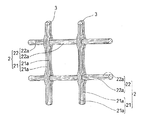
図2は、図1のII部を拡大した図であって、網材2を詳細に説明した図である。網材2は、ガラス繊維、金属繊維、合成樹脂繊維などの繊維21a,21a,…を束ね、その外周に耐アルカリ処理を施した経糸材21,21,…と、同様の素材の繊維22a,22a,…とからなる緯糸材22,22,…をからみ織りすることによって製作される。例えば、図示するように、経糸材21,21,…の各貫通部に緯糸材22,22,…を通した態様に成形でき、このような形態に織り合せることで網目の目ずれを防止することができる。
FIG. 2 is an enlarged view of a portion II in FIG. 1 and illustrates the net 2 in detail. The
例えば、経糸材21の断熱材1に当接する面(箇所)に、粘着剤3が予め塗布ないしは貼り付けられており、網材2を後述するようにローラにて加圧する等の方法により、断熱パネル10が製作される。
For example, the pressure-
図3は、パネル状の断熱材1の一方面に、網材2を粘着させることによって断熱パネル10を製造する方法を模式的に示した図である。
FIG. 3 is a diagram schematically showing a method of manufacturing the
断熱材1,1,…は、ローラ65,65,…上を順次搬送される(X方向)。一方、粘着剤が一方面に予め塗布された長尺の網材2は、ロール64に巻装されている。断熱材1,1,…の表面に網材2が順次貼着されることによってロール64がY1方向に回転し、別途のロール63を介して網材2の供給がおこなわれる(Y2方向)。ローラ65,65,…のうち、搬送されてきた断熱材1の一方面に網材2を貼着させるエリアには、断熱材1上に位置決めされた網材2を、上下から加圧しながら粘着させるための対向する2つの加圧ロール61,62が配設されている。この加圧ロール61,62は、昇降可能に構成されており(Z方向)、双方の間隔を通過する断熱材1の厚みに対して適宜のロールクリアランスを形成することにより、加圧力が調整されるようになっている。
The
断熱材1,1,…のそれぞれの一方面に網材2が貼着された後は、不図示のカッター等にて網材2が断熱材1の寸法に切断され、断熱パネル10,10,…が順次製造される。
After the
図4は、施工済みの建築物の壁4の一方面に、他の実施の形態の断熱パネル10A,10Aを取付ける状況を説明した図である。なお、断熱パネルは外断熱工法によって壁の外側に取付けられてもよいし、内断熱工法によって壁の内側に取付けられてもよい。
Drawing 4 is a figure explaining the situation where
断熱パネル10Aを構成する断熱材1aのうち、隣接する断熱パネル10Aと当接する端面には、端面同士で嵌め合いが可能な凹凸部1a1が形成されている。このような嵌め合い構造とすることにより、断熱パネル同士の接続強度を高めることができる。さらに、建築物の壁施工用の型枠内に断熱パネル10A、10A,…を取付け、型枠内にコンクリートを打設する施工方法の場合において、隣接する断熱パネル10A、10A間の隙間からセメントペーストが漏洩することを効果的に防止することができる。
Of the
図示するように、壁の一方面に接着剤5を塗布し、断熱パネル10A,10A,…を双方の端面の凹凸部1a1,1a1を嵌め合わせながら順次取付けていく。
As shown in the drawing, the adhesive 5 is applied to one side of the wall, and the
図5は、図4に示すような建築物の壁に断熱パネルを取付ける方法において、隣接する断熱パネル間に段差が生じた際の補修方法を模式的に示した図である。 FIG. 5 is a diagram schematically showing a repair method when a step is generated between adjacent heat insulating panels in the method of attaching the heat insulating panels to the wall of the building as shown in FIG.
まず、図5aは、壁面に塗布した接着剤5の厚みの不均一に起因して、断熱パネル10,10間に段差tが生じた状態を示している。なお、接着剤5の厚みが不均一であることのほかに、壁施工時の施工誤差によってその表面に不陸ができ、断熱パネル間に段差が生じる場合もある。
First, FIG. 5 a shows a state in which a step t is generated between the
この段差tを解消するために、図5bに示すように、突出する側の断熱パネル10の網材2を所定の範囲だけ断熱材1から剥がす。
In order to eliminate this level difference t, as shown in FIG. 5b, the
網材2の一部を断熱材1から剥がした後、図5cに示すように、突出する側の断熱材の表面を鑢がけやサンダーがけ等することによって段差tを解消する。例えば、図示するように双方の隣接端をすりつけるように補修することができる。
After part of the
段差tを解消した後に、図5dに示すように、剥がした網材2を、補修後の断熱材1の表面に再粘着させることにより、段差を解消する補修施工が完了する。
After eliminating the level difference t, as shown in FIG. 5d, the repair work for eliminating the level difference is completed by re-adhering the peeled
なお、型枠内で建築物の壁と断熱パネルとを一体に取付ける方法の場合であって、セメントペーストが網材の粘着された断熱パネル面側に漏洩/硬化している場合においても、網材の一部または全部を剥がし、網材と断熱材の双方からセメントペーストを取り除き、網材を断熱材に再粘着させる方法で補修することができる。 Even in the case where the building wall and the heat insulation panel are integrally attached within the formwork, and the cement paste is leaked / cured to the side of the heat insulation panel to which the mesh material is adhered, the net It can be repaired by removing a part or all of the material, removing the cement paste from both the mesh material and the heat insulating material, and re-adhering the net material to the heat insulating material.
断熱パネルとしては、押出法ポリスチレンフォーム(JIS A9511 XPSb類3種(積水化成品工業(株)製)、30〜50mm厚、スキン層除去品)や、ビーズ法ポリスチレンフォーム(JIS A9511 EPS1〜4号品、30〜80mm厚、スキン層除去品)を使用できる。 As the heat insulation panel, extruded polystyrene foam (JIS A9511 XPSb type 3 (manufactured by Sekisui Plastics Co., Ltd.), 30-50 mm thickness, skin layer removed product) and beaded polystyrene foam (JIS A9511 EPS1-4). Product, 30-80 mm thick, skin layer removed product).
また、図3に示す製造方法において、断熱材として、JISA9511XPSb類3種で厚みが30mmのもの(製品名:エスレンフォームSU(積水化成品工業(株)製))を使用し、加圧ロール61,62のロールクリアランスを断熱材の厚み(30mm)に設定し、網材として、耐アルカリガラスファイバーメッシュ(からみ織り品)(製品名:GFN−1((株)トラルマックス製)を使用し、粘着剤として、アクリル共重合体水性エマルジョン(塗布量24g/m2)(製品名:エスダイン#7110(積水フーラー(株)製)をそれぞれ使用して、断熱パネルを製造することができる。なお、断熱材の厚みに対して、加圧ロール61,62のロールクリアランスを広狭させることにより、断熱材に網材を貼着させる際の圧力を変化させ、断熱材に対する網材の剥離強度を適宜の値に調整することができる。下記の剥離試験においては、上記仕様の断熱材、粘着剤、網材から断熱パネルを製作するとともに、断熱材に網材を貼着させる際の圧力を変化させることにより、複数の断熱パネルの実施例を製作して試験をおこなった。 Moreover, in the manufacturing method shown in FIG. 3, as a heat insulating material, three types of JIS A9511 XPSs having a thickness of 30 mm (product name: Eslenfoam SU (manufactured by Sekisui Plastics Co., Ltd.)) are used, and a pressure roll The roll clearance of 61, 62 is set to the thickness of the heat insulating material (30 mm), and an alkali-resistant glass fiber mesh (a woven product) (product name: GFN-1 (manufactured by Tralmax Co., Ltd.)) is used as the netting material. As the pressure-sensitive adhesive, an acrylic copolymer aqueous emulsion (coating amount: 24 g / m 2 ) (product name: Sdyne # 7110 (manufactured by Sekisui Fuller Co., Ltd.)) can be used to manufacture a heat insulating panel. The pressure at the time of adhering the netting material to the heat insulating material by widening and narrowing the roll clearance of the pressure rolls 61 and 62 with respect to the thickness of the heat insulating material. The peel strength of the mesh material with respect to the heat insulating material can be adjusted to an appropriate value.In the following peel test, a heat insulating panel is manufactured from the heat insulating material, adhesive, and net material having the above specifications, and the heat insulating material. A plurality of heat insulation panel examples were manufactured and tested by changing the pressure at the time of adhering the mesh material.
[剥離試験およびその結果]
以下に、実施した剥離試験についてその方法と試験結果について説明する。試験に使用する断熱パネルは、上記仕様の断熱材(厚みが30mm)、粘着剤、網材から製作するとともに、ロールクリアランスが31.5mmの場合に製作される断熱パネルを実施例1とし、ロールクリアランスが30mmの場合に製作される断熱パネルを実施例2とし、ロールクリアランスが29mmの場合に製作される断熱パネルを実施例3とし、ロールクリアランスが28mmの場合に製作される断熱パネルを実施例4とする。また、比較例として、断熱材、粘着剤、網材を実施例と同仕様のものを使用し、ロールクリアランスを32.5mmとして製作された断熱パネルを比較例1とする。また、酢酸ビニルエマルジョン系接着剤(塗布量24g/m2)(製品名:R194((株)セメダイン製)にて断熱材と網材を強固に接着し、ロールクリアランスを31.5mmに設定して製作された断熱パネルを比較例2とし、ロールクリアランスを29mmに設定して製作された断熱パネルを比較例3とする。
[Peel test and results]
Below, the method and test result are demonstrated about the implemented peeling test. The heat insulation panel used for the test is manufactured from the heat insulation material (thickness of 30 mm), the adhesive, and the net material having the above specifications, and the heat insulation panel produced when the roll clearance is 31.5 mm is defined as Example 1, and the roll A heat insulating panel manufactured when the clearance is 30 mm is referred to as Example 2, a heat insulating panel manufactured when the roll clearance is 29 mm is referred to as Example 3, and a heat insulating panel manufactured when the roll clearance is 28 mm is described as the Example. 4 Further, as a comparative example, a heat insulating panel manufactured using a heat insulating material, a pressure-sensitive adhesive, and a net material having the same specifications as those of the example and having a roll clearance of 32.5 mm is referred to as a comparative example 1. In addition, a heat insulating material and a net material are firmly bonded with a vinyl acetate emulsion-based adhesive (application amount: 24 g / m 2 ) (product name: R194 (manufactured by Cemedine Co., Ltd.), and the roll clearance is set to 31.5 mm. The heat insulating panel manufactured in this way is referred to as Comparative Example 2, and the heat insulating panel manufactured with the roll clearance set to 29 mm is referred to as Comparative Example 3.
剥離試験方法は、テンション万能試験機UCT−10T((株)オリエンテック製)を使用し、20mm幅で200mm長さの網材が粘着ないしは接着された断熱材に対し、網材を90度の方向に、100mm/minの速度で剥離させた際の剥離強度を次式で算出し、その結果を表1に示す。 The peel test method uses a tension universal testing machine UCT-10T (manufactured by Orientec Co., Ltd.), and the mesh material is 90 degrees with respect to the heat insulating material to which a 20 mm wide and 200 mm long mesh material is adhered or bonded. The peel strength when peeled in the direction at a speed of 100 mm / min was calculated by the following equation, and the results are shown in Table 1.
[数1]
剥離強度(gf/20mm幅)=最大点荷重(gf)/試験片幅(20mm)
[Equation 1]
Peel strength (gf / 20 mm width) = maximum point load (gf) / test specimen width (20 mm)
なお、表1において、初期の剥離強度は所定のロールクリアランスで断熱材と網材とを最初に貼着させた際の剥離強度である。また、再粘着の剥離強度は、剥離後に同じ所定のロールクリアランスにて断熱材と網材とを再粘着させた際の剥離強度である。 In Table 1, the initial peel strength is the peel strength when the heat insulating material and the net material are first attached with a predetermined roll clearance. The re-adhesion peel strength is the peel strength when the heat insulating material and the net material are re-adhered with the same predetermined roll clearance after peeling.

表1において、作業性の合否は、10人の作業員のうち、5人以上が網材の剥離が困難、あるいは網材が再粘着しないとして、作業し難いと判断した場合に否と判定する官能試験に基づくものである。表1からも明らかなように、初期の剥離強度が20gf/20mm幅の比較例1では、再粘着が極めて困難となり、本発明の断熱パネルの目的を達することができない。一方、実施例1〜4と異なり、接着強度が強固な接着剤にて断熱材と網材を接着した比較例2,3では、初期の剥離強度が750gf/20mm幅を超える812gf/20mm幅、992gf/20mm幅となり、この場合には、作業性が悪くなる結果となった。また、断熱材が材料破壊を起しており、再粘着は極めて困難であった。 In Table 1, the pass / fail of workability is determined to be negative when it is determined that it is difficult to work because it is difficult for five or more of the ten workers to peel off the net material or the net material does not re-adhere. This is based on a sensory test. As is clear from Table 1, in Comparative Example 1 having an initial peel strength of 20 gf / 20 mm width, re-adhesion becomes extremely difficult and the purpose of the heat insulating panel of the present invention cannot be achieved. On the other hand, unlike Examples 1 to 4, in Comparative Examples 2 and 3 in which the heat insulating material and the net material were bonded with an adhesive having a strong adhesive strength, the initial peel strength was 812 gf / 20 mm width exceeding 750 gf / 20 mm width, 992 gf / 20 mm width, and in this case, the workability deteriorated. Moreover, the heat insulating material caused material destruction, and re-adhesion was extremely difficult.
実施例1〜4では、良好な粘着状態の網材が断熱材の部材破壊を起こすことなく剥がれ、再粘着時にも問題のない剥離強度を保持している。 In Examples 1-4, the net material in a good adhesive state peels without causing the member destruction of the heat insulating material, and maintains a peel strength that causes no problem even during re-adhesion.
上記の剥離試験の結果、粘着剤による断熱材と網材との粘着力(剥離強度)は、20〜750gf/20mm幅の範囲にあることが望ましいと結論付けることができる。 As a result of the above peeling test, it can be concluded that the adhesive strength (peeling strength) between the heat insulating material and the netting material is preferably in the range of 20 to 750 gf / 20 mm width.
以上、本発明の実施の形態を図面を用いて詳述してきたが、具体的な構成はこの実施形態に限定されるものではなく、本発明の要旨を逸脱しない範囲における設計変更等があっても、それらは本発明に含まれるものである。 The embodiment of the present invention has been described in detail with reference to the drawings. However, the specific configuration is not limited to this embodiment, and there are design changes and the like without departing from the gist of the present invention. They are also included in the present invention.
1,1a…断熱材、1a1…凹凸部、2…網材、21…経糸材、21a…繊維、22…緯糸材、22a…繊維、3…粘着剤、4…壁、5…接着剤、10,10A…断熱パネル
DESCRIPTION OF
Claims (5)
壁を施工するための型枠を設置し、網材が型枠側となるように複数の断熱パネルを所定の型枠面に取付ける第1の工程と、型枠内にコンクリートを打設し、その硬化を待って脱型する第2の工程と、を含み、セメントペーストが断熱材の網材貼着側に漏洩している場合には、いずれか一方または双方の断熱パネルの網材の一部を剥がし、断熱材の表面と網材からセメントペーストを取り除き、剥がした網材を断熱材に再粘着する第3の工程をさらに含むことを特徴とする断熱パネルの取付け方法。 A heat insulating panel mounting method for mounting a heat insulating panel consisting of a panel-shaped heat insulating material made of foamed resin and a net material that can be peeled and re-adhered to one surface of the panel to a wall surface of a building. And
A first step of installing a formwork for constructing the wall, attaching a plurality of heat insulation panels to a predetermined formwork surface so that the netting material is on the formwork side, and placing concrete in the formwork; A second step of demolding after waiting for the hardening, and when the cement paste is leaking to the netting side of the heat insulating material, one of the net materials of one or both of the heat insulating panels A method for attaching a heat insulating panel, further comprising a third step of peeling the part, removing cement paste from the surface of the heat insulating material and the net material, and re-adhering the peeled net material to the heat insulating material.
建築物の壁を施工する第1の工程と、壁面に複数の断熱パネルを貼着する第2の工程と、を含み、隣接する断熱パネルの間に段差が生じた場合には、いずれか一方または双方の断熱パネルの網材の一部を剥がし、断熱材の表面を削りながら段差を解消し、剥がした網材を断熱材に再粘着する第3の工程をさらに含むことを特徴とする断熱パネルの取付け方法。 A heat insulating panel mounting method for mounting a heat insulating panel consisting of a panel-shaped heat insulating material made of foamed resin and a net material that can be peeled and re-adhered to one surface of the panel to a wall surface of a building. And
Including a first step of constructing a wall of a building and a second step of adhering a plurality of heat insulation panels to a wall surface, and if one or more steps occur between adjacent heat insulation panels Alternatively, the heat insulation further includes a third step in which a part of the mesh material of both heat insulation panels is peeled off, the step is eliminated while the surface of the heat insulation material is shaved, and the removed mesh material is re-adhered to the heat insulation material. How to install the panel.
Priority Applications (1)
| Application Number | Priority Date | Filing Date | Title |
|---|---|---|---|
| JP2006021704A JP4732176B2 (en) | 2006-01-31 | 2006-01-31 | Insulation panel and method of installing the insulation panel |
Applications Claiming Priority (1)
| Application Number | Priority Date | Filing Date | Title |
|---|---|---|---|
| JP2006021704A JP4732176B2 (en) | 2006-01-31 | 2006-01-31 | Insulation panel and method of installing the insulation panel |
Publications (2)
| Publication Number | Publication Date |
|---|---|
| JP2007204923A JP2007204923A (en) | 2007-08-16 |
| JP4732176B2 true JP4732176B2 (en) | 2011-07-27 |
Family
ID=38484625
Family Applications (1)
| Application Number | Title | Priority Date | Filing Date |
|---|---|---|---|
| JP2006021704A Active JP4732176B2 (en) | 2006-01-31 | 2006-01-31 | Insulation panel and method of installing the insulation panel |
Country Status (1)
| Country | Link |
|---|---|
| JP (1) | JP4732176B2 (en) |
Families Citing this family (3)
| Publication number | Priority date | Publication date | Assignee | Title |
|---|---|---|---|---|
| KR100960045B1 (en) * | 2009-07-31 | 2010-05-31 | 주식회사 코폼 | A wall absorbing sheet and manufacturing device and method thereof |
| KR101649563B1 (en) * | 2015-10-21 | 2016-08-19 | 이훈 | The glass fiber with wire and construction method for waterproof using there of |
| CN112814183B (en) * | 2021-02-06 | 2022-08-09 | 广东省第四建筑工程有限公司 | Building wall energy-saving heat-insulating structure |
Family Cites Families (1)
| Publication number | Priority date | Publication date | Assignee | Title |
|---|---|---|---|---|
| JPS5079925A (en) * | 1973-11-15 | 1975-06-28 |
-
2006
- 2006-01-31 JP JP2006021704A patent/JP4732176B2/en active Active
Also Published As
| Publication number | Publication date |
|---|---|
| JP2007204923A (en) | 2007-08-16 |
Similar Documents
| Publication | Publication Date | Title |
|---|---|---|
| US6692595B2 (en) | Carbon fiber reinforcement system | |
| JP2004027718A (en) | Sheet for repair / reinforcement / deterioration prevention of concrete structure and repair / reinforcement / deterioration prevention method of concrete structure | |
| JP2004027718A5 (en) | ||
| JP5753524B2 (en) | Film for curing concrete structures | |
| KR20130019653A (en) | Urethane waterproof membrane structure comprising fiber reinforced mesh, and construction method thereof | |
| JP4732176B2 (en) | Insulation panel and method of installing the insulation panel | |
| JP2002256707A (en) | Sheet and method for repairing and reinforcing concrete structure | |
| JP6203441B1 (en) | Anti-peeling sheet, anti-peeling method, and anti-peeling repair method | |
| US20220111608A1 (en) | Wall and ceiling repair products and methods | |
| JP2007315169A (en) | Heat-insulating waterproof repair method and repair structure | |
| KR20020055567A (en) | Sheet for repair and reinforcement of concrete structure and method thereof | |
| JP5485502B2 (en) | Wall repair structure | |
| JP2002235444A (en) | Repairing execution method for concrete structure | |
| JP2007177462A (en) | Fiber reinforced skeleton structure and its manufacturing method | |
| JP7153995B1 (en) | Coating agent application method, fiber sheet, and fiber sheet construction method | |
| JP2005155051A (en) | Repairing/reinforcing method of concrete structure | |
| CN115182615A (en) | Carbon fiber reinforcing method for assembled multifunctional ward floor bearing plate | |
| JP2000310023A (en) | Pressure sensitive adhesive sheet and joint processing method of backing material using it | |
| JP3333768B2 (en) | Reinforcement and repair method of reinforced concrete mortar finished structure | |
| JP6699157B2 (en) | Existing outer wall repair structure and existing outer wall repair method | |
| JP2009097250A (en) | Wall surface structure of alc panel | |
| JP6996072B2 (en) | Renovation structure of existing outer wall and renovation method of existing outer wall | |
| EP3954841A2 (en) | A layered component | |
| KR100422246B1 (en) | Method for carrying out a seat for draining water off of a rooftop | |
| JP2011208418A (en) | Construction method for preventing flaking of ceiling alc slab |
Legal Events
| Date | Code | Title | Description |
|---|---|---|---|
| A621 | Written request for application examination |
Free format text: JAPANESE INTERMEDIATE CODE: A621 Effective date: 20080908 |
|
| TRDD | Decision of grant or rejection written | ||
| A01 | Written decision to grant a patent or to grant a registration (utility model) |
Free format text: JAPANESE INTERMEDIATE CODE: A01 Effective date: 20110405 |
|
| A01 | Written decision to grant a patent or to grant a registration (utility model) |
Free format text: JAPANESE INTERMEDIATE CODE: A01 |
|
| A61 | First payment of annual fees (during grant procedure) |
Free format text: JAPANESE INTERMEDIATE CODE: A61 Effective date: 20110420 |
|
| FPAY | Renewal fee payment (event date is renewal date of database) |
Free format text: PAYMENT UNTIL: 20140428 Year of fee payment: 3 |
|
| R150 | Certificate of patent or registration of utility model |
Ref document number: 4732176 Country of ref document: JP Free format text: JAPANESE INTERMEDIATE CODE: R150 |