JP4725307B2 - Inkjet printer - Google Patents
Inkjet printer Download PDFInfo
- Publication number
- JP4725307B2 JP4725307B2 JP2005344139A JP2005344139A JP4725307B2 JP 4725307 B2 JP4725307 B2 JP 4725307B2 JP 2005344139 A JP2005344139 A JP 2005344139A JP 2005344139 A JP2005344139 A JP 2005344139A JP 4725307 B2 JP4725307 B2 JP 4725307B2
- Authority
- JP
- Japan
- Prior art keywords
- frequency characteristic
- drive signal
- ink
- ink droplet
- signal
- Prior art date
- Legal status (The legal status is an assumption and is not a legal conclusion. Google has not performed a legal analysis and makes no representation as to the accuracy of the status listed.)
- Active
Links
Images


Landscapes
- Particle Formation And Scattering Control In Inkjet Printers (AREA)
Description
本発明は、例えば複数色の液体インクの微小なインク滴を複数のノズルから吐出してその微粒子(インクドット)を印刷媒体上に形成することにより、所定の文字や画像を描画するようにしたインクジェットプリンタの駆動装置及びその駆動方法に関するものである。 In the present invention, for example, minute characters of liquid inks of a plurality of colors are ejected from a plurality of nozzles to form fine particles (ink dots) on a print medium, thereby drawing a predetermined character or image. The present invention relates to an inkjet printer driving apparatus and a driving method thereof.
このようなインクジェットプリンタは、一般に安価で且つ高品質のカラー印刷物が容易に得られることから、パーソナルコンピュータやデジタルカメラなどの普及に伴い、オフィスのみならず一般ユーザにも広く普及してきている。
このようなインクジェットプリンタは、一般に、インクカートリッジと印字ヘッド(インクジェットヘッドともいう)とが一体的に備えられたキャリッジなどと称される移動体が印刷媒体上をその搬送方向と交差する方向に往復しながらその印字ヘッドのノズルから液体インク滴を吐出(噴射)して印刷媒体上に微小なインクドットを形成することで、当該印刷媒体上に所定の文字や画像を描画して所望の印刷物を作成するようになっている。そして、このキャリッジに黒色(ブラック)を含めた4色(イエロー、マゼンタ、シアン)のインクカートリッジと各色毎の印字ヘッドを備えることで、モノクロ印刷のみならず、各色を組み合わせたフルカラー印刷も容易に行えるようになっている(更に、これらの各色に、ライトシアンやライトマゼンタなどを加えた6色や7色、或いは8色のものも実用化されている)。
Such an inkjet printer is generally inexpensive and can easily obtain a high-quality color printed matter. Accordingly, along with the widespread use of personal computers and digital cameras, it has become widespread not only in offices but also in general users.
In such an ink jet printer, a moving body called a carriage or the like, which is integrally provided with an ink cartridge and a print head (also referred to as an ink jet head), generally reciprocates on a print medium in a direction intersecting the transport direction. While ejecting (injecting) liquid ink droplets from the nozzles of the print head to form minute ink dots on the print medium, a predetermined character or image is drawn on the print medium to produce a desired printed matter. It is designed to create. The carriage is equipped with four color (yellow, magenta, cyan) ink cartridges including black (black) and a print head for each color, so that not only monochrome printing but also full-color printing combining each color is easy. (Furthermore, 6 colors, 7 colors, or 8 colors in which light cyan, light magenta, etc. are added to these colors are also put into practical use).
このようなインクジェットプリンタでは、駆動信号によってアクチュエータを駆動して圧力室内の圧力を変化せしめ、その圧力変化で当該圧力室内のインクを当該圧力室に連通するノズルからインク滴として吐出する。アクチュエータにも幾つかの種類があり、例えばピエゾ方式のインクジェットプリンタでは、アクチュエータであるピエゾ(圧電)素子に駆動信号を印加すると圧力室に接する振動板が変位し、これにより圧力室内の圧力が変化してインク滴が吐出される。 In such an ink jet printer, the actuator is driven by a drive signal to change the pressure in the pressure chamber, and the ink in the pressure chamber is ejected as an ink droplet from a nozzle communicating with the pressure chamber by the pressure change. There are also several types of actuators. For example, in a piezoelectric inkjet printer, when a drive signal is applied to a piezoelectric (piezoelectric) element, which is an actuator, the diaphragm in contact with the pressure chamber is displaced, thereby changing the pressure in the pressure chamber. Ink droplets are discharged.
ところで、この種のインクジェットプリンタでは、印刷所要時間の短縮、駆動回路の簡素化、信号線数の低減化などを目的として、複数のノズルのアクチュエータに共通の駆動信号を印加するようにしている。つまり、同じ駆動信号を複数のアクチュエータに同時に供給するのであり、このような場合、一つの駆動信号に複数のアクチュエータが並列に接続されることになる。接続されるアクチュエータは、インク滴を吐出すべきノズル、つまり印字データに応じて選択される。このように一つの駆動信号に接続されるアクチュエータの数が変化する場合、その接続数に応じてインク滴の吐出特性が変化することが明らかになってきた。そこで、下記特許文献1に記載されるインクジェットプリンタでは、実際に駆動されるアクチュエータ(又はノズル)の数を求め、その数に応じて、インク滴吐出用の駆動信号そのものを変更設定している。具体的には、台形波状電圧信号からなる駆動信号の電圧増減の傾き或いは波高値そのものを変更することにより、インク滴吐出特性の安定化を図っている。
しかしながら、前記従来のインクジェットプリンタでは、インク滴吐出特性を或る程度安定化することができるものの、より一層の改善が望まれる。即ち、ピエゾ素子などからなるアクチュエータには、加工バラツキや発熱係数などの個体差があり、実際に駆動されるアクチュエータ数分の累積差が発生する上に、選択されるアクチュエータによっても累積値が異なる。これは、より多くのアクチュエータを同時に駆動するラインヘッド型インクジェットプリンタで顕著になる。 However, in the conventional ink jet printer, although the ink droplet ejection characteristics can be stabilized to some extent, further improvement is desired. In other words, actuators composed of piezo elements have individual differences such as processing variations and heat generation coefficients. Cumulative differences occur for the number of actuators that are actually driven, and the cumulative values also differ depending on the selected actuator. . This becomes remarkable in a line head type ink jet printer that simultaneously drives more actuators.
本発明は、上記のような問題点に着目してなされたものであり、実際に駆動されるアクチュエータを含む駆動回路の周波数特性と逆の周波数特性の成分を本来のインク滴吐出用駆動信号に加えることによってインク滴吐出特性を安定化することができるインクジェットプリンタを提供することを目的とするものである。 The present invention has been made paying attention to the above-described problems, and a component having a frequency characteristic opposite to the frequency characteristic of a drive circuit including an actually driven actuator is used as an original ink droplet ejection drive signal. It is an object of the present invention to provide an ink jet printer that can stabilize ink droplet ejection characteristics by adding.
[発明1]上記課題を解決するために、発明1のインクジェットプリンタは、インク滴を吐出するノズルのアクチュエータにインク滴吐出用駆動信号を印加する駆動手段を備えたインクジェットプリンタであって、前記インク滴を吐出するノズルのアクチュエータに対して周波数特性検出用駆動信号を印加したときの前記アクチュエータを含む駆動回路の周波数特性を検出し、前記周波数特性と逆の周波数特性のフィルタに前記インク滴吐出用駆動信号を通し、前記周波数特性と逆の周波数特性のフィルタ通過成分を前記インク滴吐出用駆動信号に加えて前記駆動回路に供給することを特徴とするものである。 [Invention 1] In order to solve the above problems, an ink jet printer of the invention 1, an ink jet printer having a driving means to apply a drive signal for ink droplet ejection actuator of nozzles for ejecting Lee ink droplets, detecting the frequency characteristic of the driving circuit including the actuator upon application of a frequency characteristic detection drive signal to the actuator of nozzles for discharging the ink droplets, the ink in the filter of the frequency characteristic and the inverse of the frequency characteristic through droplet ejection drive signal, and characterized by supplying a filter pass component of the frequency characteristic and the inverse of the frequency characteristics to hear dynamic circuit before addition to the ink droplet ejection drive signal.
本願発明者等は、例えばピエゾ素子からなるアクチュエータのもつ静電容量と配線の寄生インダクタンスや抵抗成分が一種のローパスフィルタを形成し、これにより駆動信号の高周波成分が除去されて、所謂鈍りが発生し駆動信号に歪みが発生してしまうことを見出した。しかも、このローパスフィルタの周波数特性は、前述したように、選択されるアクチュエータ及びその数によって異なる。そこで、この発明1に係るインクジェットプリンタによれば、インク滴を吐出すべきノズルのアクチュエータに対して周波数特性検出用駆動信号を印加し、そのときのアクチュエータを含む駆動回路の周波数特性を検出し、その周波数特性と逆の周波数特性のフィルタにインク滴吐出用駆動信号を通し、そのフィルタ通過成分を本来のインク滴吐出用駆動信号に加えて前記アクチュエータを含む駆動回路に供給する構成としたため、実際にアクチュエータに印加される駆動信号は本来のインク滴吐出用駆動信号に一致又はほぼ一致し、個々のノズルのインク滴吐出特性を理想状態に近づけて安定化することができる。 The inventors of the present application, for example, form a low-pass filter in which the capacitance of the actuator made of a piezoelectric element and the parasitic inductance and resistance component of the wiring form a kind of low-pass filter, thereby removing the high-frequency component of the drive signal, so-called dullness occurs. It was found that the drive signal is distorted. Moreover, the frequency characteristics of the low-pass filter differ depending on the selected actuator and the number thereof as described above. Therefore, according to the ink jet printer according to the first aspect of the present invention, the frequency characteristic detection drive signal is applied to the actuator of the nozzle that should eject ink droplets, and the frequency characteristic of the drive circuit including the actuator at that time is detected. Since the ink droplet ejection drive signal is passed through a filter having a frequency characteristic opposite to that frequency characteristic, the filter passing component is supplied to the drive circuit including the actuator in addition to the original ink droplet ejection drive signal. In addition, the drive signal applied to the actuator coincides with or substantially coincides with the original ink droplet ejection drive signal, and the ink droplet ejection characteristics of the individual nozzles can be stabilized close to the ideal state.
[発明2]発明2のインクジェットプリンタは、ノズルに対して設けられたアクチュエータと、印刷データに基づいて何れのノズルからどの程度の量のインク滴を吐出するかを示す印字データを出力する印字データ出力手段と、前記印字データに基づいてインク滴を吐出するノズルのアクチュエータにインク滴吐出用駆動信号を印加して当該ノズルからインク滴を吐出する駆動手段とを備え、前記駆動手段は、前記インク滴吐出用駆動信号の前段にインク滴非吐出の周波数特性検出用駆動信号を時系列的に配列する周波数特性検出用駆動信号設定手段、前記印字データに基づいて何れのアクチュエータに前記周波数特性検出用駆動信号及び前記インク滴吐出用駆動信号を印加するかを選択し選択された1つ又は複数のアクチュエータに同一の前記周波数特性検出用駆動信号及び前記インク滴吐出用駆動信号を印加する選択手段、前記周波数特性検出用駆動信号が印加されたときの前記アクチュエータを含む前記駆動回路の周波数特性を検出する周波数特性検出手段、前記周波数特性検出手段で検出された前記周波数特性と逆の周波数特性の逆周波数特性フィルタを設定する逆周波数特性フィルタ設定手段、前記インク滴吐出用駆動信号が前記逆周波数特性フィルタを通過した周波数成分を当初のインク滴吐出用駆動信号に加えて前記駆動回路に供給する周波数特性修正済駆動信号出力手段を備えたことを特徴とするものである。 [Invention 2] invention 2 of the ink jet printer, outputs print data representing the actuator provided for the Bruno nozzle, or to discharge ink droplets of the amount of the degree of any nozzle or rads based on the print data comprising: a print data output means, and driving means for pre-applying a drive signal for ink droplet ejection actuator of the nozzles which eject ink droplets based on Kishirushi character data for ejecting ink droplets from the nozzle, the drive means, before Symbol ink droplet ejection drive signal preceding the ink droplet non-ejection frequency characteristic detection drive signal setting means to sequence chronological order frequency characteristic detection drive signal of any based on said print data actuator to the frequency characteristic detection drive signal and the ink droplet ejection driving signals one is selected-option selection whether to apply or to a plurality of actuators same Serial frequency characteristic detection drive signal and selection means to apply the ink droplet ejection driving signal, the frequency characteristic of detecting a frequency characteristic of the drive circuit including the actuator when the frequency characteristic detection drive signal is applied detection hand stage, the inverse frequency characteristic filter setting means to set the inverse frequency characteristic filter of the frequency characteristic detected by the detecting means that said frequency characteristic opposite frequency characteristics, the ink droplet ejection driving signal is the inverse frequency characteristic filter it is characterized in that it comprises a frequency characteristic amended driving signal output hands stage supplied to the drive circuit frequency components in addition to the initial ink droplet ejection drive signal that has passed through the.
この発明2に係るインクジェットプリンタによれば、アクチュエータを含む駆動回路の周波数特性を検出するためにインク滴吐出用駆動信号の前段にインク滴非吐出の周波数特性検出用駆動信号を時系列的に配列し、印字データに基づいて何れのアクチュエータに周波数特性検出用駆動信号及びインク滴吐出用駆動信号を印加するかを選択し、選択された1つ又は複数のアクチュエータに同一の周波数特性検出用駆動信号及びインク滴吐出用駆動信号を印加すると共に、周波数特性検出用駆動信号が印加されたときのアクチュエータを含む駆動回路の周波数特性を検出し、その検出された周波数特性と逆の周波数特性の逆周波数特性フィルタを設定し、その逆周波数特性フィルタにインク滴吐出用駆動信号を通し、その通過した成分を本来のインク滴吐出用駆動信号に加えてアクチュエータを含む駆動回路に供給する構成としたため、実際にアクチュエータに印加される駆動信号は本来のインク滴吐出用駆動信号に一致又はほぼ一致し、個々のノズルのインク滴吐出特性を理想状態に近づけて安定化することができる。 According to the ink jet printer of the second aspect, in order to detect the frequency characteristic of the drive circuit including the actuator, the frequency characteristic detection drive signal for non-ink droplet ejection is arranged in time series before the ink droplet ejection drive signal. And selecting which actuator to apply the frequency characteristic detection drive signal and the ink droplet ejection drive signal to the actuator based on the print data, and the same frequency characteristic detection drive signal to one or more selected actuators. In addition, the ink droplet ejection drive signal is applied, and the frequency characteristic of the drive circuit including the actuator is detected when the frequency characteristic detection drive signal is applied, and the reverse frequency of the frequency characteristic opposite to the detected frequency characteristic is detected. Set the characteristic filter, and pass the ink droplet ejection drive signal through the inverse frequency characteristic filter. In addition to the ink droplet discharge drive signal, the drive signal is supplied to the drive circuit including the actuator. Therefore, the drive signal actually applied to the actuator matches or substantially matches the original ink droplet discharge drive signal. The ink droplet ejection characteristics can be stabilized close to the ideal state.
[発明3]発明3のインクジェットプリンタは、前記発明2のインクジェットプリンタにおいて、前記周波数特性検出用駆動信号設定手段は、前記インク滴吐出用駆動信号が時系列的に連結される場合には個々の前記インク滴吐出用駆動信号の前段全てに前記周波数特性検出用駆動信号を配列し、前記逆周波数特性フィルタ設定手段は、前記周波数特性検出手段で検出された個々の周波数特性検出用駆動信号印加時の周波数特性に基づいて前記周波数特性と逆の周波数特性の前記逆周波数特性フィルタを設定することを特徴とするものである。
[Invention 3]
この発明3に係るインクジェットプリンタによれば、インク滴吐出用駆動信号が時系列的に連結される場合には個々のインク滴吐出用駆動信号の前段全てに周波数特性検出用駆動信号を配列し、検出された個々の周波数特性検出用駆動信号印加時の周波数特性に基づいてその逆の周波数特性の逆周波数特性フィルタを設定する構成としたため、例えば異なる解像度のインク滴を吐出するためにインク滴吐出用駆動信号を時系列的に連結する場合でも、アクチュエータに印加される実際の各駆動信号を本来のインク滴吐出用駆動信号に一致又はほぼ一致させることができる。 According to the ink jet printer according to the third aspect of the present invention, when the ink droplet ejection drive signals are connected in time series, the frequency characteristic detection drive signals are arranged in all preceding stages of the individual ink droplet ejection drive signals, Based on the detected frequency characteristics when the frequency characteristic detection drive signal is applied, the inverse frequency characteristic filter of the opposite frequency characteristic is set, so that, for example, ink droplet ejection is performed to eject ink droplets of different resolutions. Even in the case where the driving signals are connected in time series, the actual driving signals applied to the actuator can be matched or substantially matched with the original ink droplet ejection driving signal.
[発明4]発明4のインクジェットプリンタは、前記発明2又は3のインクジェットプリンタにおいて、前記周波数特性検出手段は、前記周波数特性検出用駆動信号印加時の実際の信号値を検出して高速フーリエ変換を行い、前記逆周波数特性フィルタ設定手段は、前記高速フーリエ変換された実際の信号値の特定の高周波数成分のパワースペクトル値に基づいて前記逆周波数特性フィルタを設定することを特徴とするものである。
[Invention 4] The ink jet printer according to
この発明4に係るインクジェットプリンタによれば、周波数特性検出用駆動信号印加時の実際の信号値を検出して高速フーリエ変換を行い、その高速フーリエ変換された実際の信号値の特定の高周波数成分のパワースペクトル値に基づいて逆周波数特性フィルタを設定する構成としたため、逆周波数特性フィルタを正確且つ容易に設定することが可能となる。 According to the ink jet printer according to the fourth aspect of the present invention, the actual signal value at the time of applying the frequency characteristic detection drive signal is detected, the fast Fourier transform is performed, and the specific high frequency component of the actual signal value obtained by the fast Fourier transform is detected. Since the reverse frequency characteristic filter is set based on the power spectrum value, it is possible to set the reverse frequency characteristic filter accurately and easily.
次に、本発明のインクジェットプリンタの駆動装置の第1実施形態について図面を参照しながら説明する。
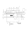
図1は、本実施形態のインクジェットプリンタ1の概略構成を示す平面図である。このインクジェットプリンタ1は、図1に示すように、ヘッドユニット2及びインクカートリッジ3を搭載したキャリッジ4を備え、このキャリッジ4は1組のキャリッジ軸5に案内されて主走査方向に移動できるようになっている。また、キャリッジ4の一部は歯付きベルト9に固定され、且つ歯付きベルト9は、モータ6の回転軸に固定された駆動プーリ7と従動プーリ8との間に掛け渡されている。
Next, a first embodiment of an ink jet printer drive device according to the present invention will be described with reference to the drawings.
FIG. 1 is a plan view showing a schematic configuration of the ink jet printer 1 of the present embodiment. As shown in FIG. 1, the ink jet printer 1 includes a
更にキャリッジ4にはエンコーダ10が取付けられ、キャリッジ4の移動方向に沿ってリニアスケール11が設けられている。これにより、エンコーダ10によりキャリッジ4上のヘッドユニット2の位置を検出するようになっている。なお、図1において、符号12はヘッドユニット2とシステムコントローラなどとを電気的に接続するケーブルであり、符号13は、後述するインクジェットヘッドの表面をクリーニングするワイパであり、符号14は、そのインクジェットヘッドのノズル基板(図3参照)のキャッピングを行うキャップである。
Further, an
このような構成からなるインクジェットプリンタ1では、エンコーダ10の検出信号がモータ制御回路(図示せず)に入力されると、そのモータ制御回路によりモータ6の回転動作が、加速、一定速度、減速、反転、加速、一定速度、減速、反転…といったように制御される。このようなモータ6の動作に伴って、キャリッジ4が主走査方向に往復移動を繰り返し、一定速度の区間が印刷領域に相当するので、その一定速度の際にキャリッジ4に搭載されるヘッドユニット2のノズルから印刷媒体a上にインク滴が吐出される。この結果、印刷媒体aには、そのインク滴からなるインクドットによって所定の文字や画像が記録(印字)される。
In the ink jet printer 1 having such a configuration, when the detection signal of the
次に、図1に示すヘッドユニット2の具体的な構成について、図2a及び図3を参照して説明する。このヘッドユニット2は、図2aに示すようなインクジェットヘッド(ノズルヘッド)20を複数個備え、各インクジェットヘッド20は圧電式アクチュエータを用いたものである。インクジェットヘッド20は、図2aに示すように、振動板21と、この振動板21を変位させる圧電式アクチュエータ22と、内部に液体であるインクが充填され且つ振動板21の変位により内部の圧力が増減されるキャビティ(圧力室)23と、このキャビティ23に連通し且つ当該キャビティ23内の圧力の増減によりインクを液滴として吐出するノズル24とを少なくとも備えている。
Next, a specific configuration of the
更に詳述すると、インクジェットヘッド20は、ノズル24が形成されたノズル基板25と、キャビティ基板26と、振動板21と、複数の圧電素子27を積層した積層型の圧電式アクチュエータ22とを備えている。キャビティ基板26は、図示のように所定形状に形成され、これにより、キャビティ23と、これに連通するリザーバ28とが形成されている。また、リザーバ28は、インク供給チューブ29を介してインクカートリッジ3に接続されている。圧電式アクチュエータ22は、対向して配置される櫛歯状の電極31、32と、その電極31、32の各櫛歯と交互に配置される圧電素子27とからなる。また、圧電式アクチュエータ22は、その一端側が図2aに示すように、中間層30を介して振動板21と接合されている。
More specifically, the
このような構成からなる圧電式アクチュエータ22では、第1電極31と第2電極32との間に印加される駆動信号源からの駆動信号により、図2aに矢印で示すように上下方向に伸び縮みするモードを利用している。従って、圧電式アクチュエータ22では、例えば図2aに示すような駆動信号が印加されると、振動板21に変位が生じてキャビティ23内の圧力が変化し、ノズル24からインク滴が吐出されるようになっている。具体的には、後段に詳述するように、キャビティ23の容積を拡大して(膨張させて)インクを引込み、次いでキャビティ23の容積を縮小して(収縮させて)インクを押出し、これによりノズルからインク滴を吐出する。なお、図2aに示すノズル基板26に形成されるインクジェットヘッド20毎のノズル24は、例えば図3に示すように配列されている。この図3の例では、4色のインク(Y:イエロー、M:マゼンタ、C:シアン、K:ブラック)に適用した場合のノズル24の配列パターンを示しており、これらの色の組合せにより所謂フルカラー印刷が可能となる。
In the
圧電式アクチュエータ22の他の例を図2bに示す。図中の符号は、図2aのものを流用している。この圧電式アクチュエータは、一般にユニモルフ型アクチュエータと呼ばれ、圧電素子27を二つの電極31、32で挟んだ簡単な構造であるが、駆動信号を印加することによって、図2aの積層型アクチュエータと同様に、図の上下方向に伸び縮みし、キャビティ23の容積を拡大してインクを引き込み、次いでキャビティ23の容積を縮小してノズル24からインク滴を吐出する。
Another example of the
前記インクジェットプリンタ1内には、自身を制御するための制御装置が設けられている。この制御装置は、例えば図4に示すように、例えばパーソナルコンピュータ、デジタルカメラ等のホストコンピュータ60から入力された印刷データに基づいて、印刷装置や給紙装置等を制御することにより印刷媒体に印刷処理を行うものである。そして、ホストコンピュータ60から入力された印刷データを受取る入力インタフェース部61と、この入力インタフェース部61から入力された印刷データに基づいて印刷処理を実行する例えばマイクロコンピュータで構成される制御部62と、キャリッジモータ41を駆動制御するキャリッジモータドライバ63と、給紙モータ51を駆動制御する給紙モータドライバ64と、インクジェットヘッド20を駆動制御するヘッドドライバ65と、各ドライバ63、64、65の出力信号を外部のキャリッジモータ41、給紙モータ51、インクジェットヘッド20で使用する制御信号に変換して出力するインタフェース67とを備えて構成される。
The inkjet printer 1 is provided with a control device for controlling itself. For example, as shown in FIG. 4, the control device prints on a print medium by controlling a printing device, a paper feeding device, and the like based on print data input from a host computer 60 such as a personal computer or a digital camera. The processing is performed. An
制御部62は、印刷処理等の各種処理を実行するCPU(Central Processing Unit)62aと、入力インタフェース61を介して入力された印刷データ或いは当該印刷データ印刷処理等を実行する際の各種データを一時的に格納し、或いは印刷処理等のアプリケーションプログラムを一時的に展開するRAM(Random Access Memory)62cと、CPU62aで実行する制御プログラム等を格納する不揮発性半導体メモリで構成されるROM(Read-Only Memory)62dとを備えている。この制御部62は、インタフェース部61を介してホストコンピュータ60から印刷データ(画像データ)を入手すると、CPU62aが、この印刷データに所定の処理を実行して、何れのノズルからインク滴を吐出するか或いはどの程度のインク滴を吐出するかという印字データを出力し、この印字データ及び各種センサからの入力データに基づいて、各ドライバ63〜65に制御信号を出力する。各ドライバ63〜65から制御信号が出力されると、これらがインタフェース部67で駆動信号に変換されてインクジェットヘッド20の複数のノズル24に対応する圧電式アクチュエータ22、キャリッジモータ41、給紙モータ51が夫々作動して、印刷媒体に印刷処理が実行される。なお、制御部62内の各構成要素は、図示しないバスを介して電気的に接続されている。
The
また、制御部62は、後述する駆動信号を形成するための波形形成用データDATAを後述する波形メモリ701に書込むために、書込みイネーブル信号DENと、書込みクロック信号WCLKと、書込みアドレスデータA0〜A3とを出力して、例えば16ビットの波形形成用データDATAを波形メモリ701に書込むと共に、この波形メモリ701に記憶された波形形成用データDATAを読出すための読出しアドレスデータA0〜A3、波形メモリ701から読出した波形形成用データDATAをラッチするタイミングを設定する第1のクロック信号ACLK、ラッチした波形データを加算するためのタイミングを設定する第2のクロック信号BCLK及びラッチデータをクリアするクリア信号CLERをヘッドドライバ65に出力する。
Further, the
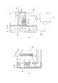
ヘッドドライバ65は、駆動信号COMを形成する駆動信号発生回路70と、クロック信号SCKを出力する発振回路71とを備えている。駆動信号発生回路70は、図5に示すように、制御部62から入力される駆動信号生成のための波形形成用データDATAを所定のアドレスに対応する記憶素子に記憶する波形メモリ701と、この波形メモリ701から読出された波形形成用データDATAを前述した第1のクロック信号ACLKによってラッチするラッチ回路702と、ラッチ回路702の出力と後述するラッチ回路704から出力される波形生成データWDATAとを加算する加算器703と、この加算器703の加算出力を前述した第2のクロック信号BCLKによってラッチするラッチ回路704と、このラッチ回路704から出力される波形生成データWDATAに所定のハイパスフィルタ処理を施すディジタルフィルタ回路708と、このディジタルフィルタ回路708から出力される波形生成データ高周波数成分WDATAHを選択信号WNに応じて通過選択するスイッチ709と、前記ラッチ回路704から出力される波形生成データWDATAとスイッチ709を通過した波形生成データ高周波数成分WDATAHとを加算する加算器710と、この加算器710の出力、つまり周波数特性修正済波形生成データWDATASをアナログ信号に変換するD/A変換器705と、このD/A変換器705から出力されるアナログ信号を電圧増幅する電圧増幅部706と、この電圧増幅部706の出力信号を電流増幅して駆動信号COMを圧電式アクチュエータ22に向けて出力する電流増幅部707と、圧電式アクチュエータ22を含む駆動回路の実際の駆動信号COMの周波数特性を高速フーリエ変換によって検出する周波数特性算出器712と、この周波数特性算出器712で検出された実際の駆動信号COMの周波数特性と逆の周波数特性を備えた逆周波数特性フィルタ(高域通過フィルタ)を前記ディジタルフィルタ回路708中から選択する逆周波数特性フィルタ選択回路711とを備えている。ここで、ラッチ回路702、704には制御部62から出力されるクリア信号CLERが入力され、このクリア信号CLERがオフ状態となったときに、ラッチデータがクリアされる。
The
波形メモリ701は、図6に示すように、指示したアドレスに夫々数ビットずつのメモリ素子が配列され、アドレスA0〜A3と共に波形データDATAが記憶される。具体的には、制御部62から指示したアドレスA0〜A3に対して、クロック信号WCLKと共に波形データDATAが入力され、書込みイネーブル信号DENの入力のよってメモリ素子に波形データDATAが記憶される。
As shown in FIG. 6, in the
インクジェットヘッド20には、入出力インタフェース部67を介して、駆動信号発生回路70で生成された駆動信号COM、印刷データに基づいて吐出するノズルを選択すると共に圧電式アクチュエータ22の駆動信号COMへの接続タイミングを決定する駆動波形信号選択データ信号SI、全ノズルにノズル選択データが入力された後、駆動波形信号選択データSIに基づいて駆動信号COMとインクジェットヘッド20の圧電式アクチュエータ22とを接続させるラッチ信号LAT及びチャンネル信号CH、駆動波形信号選択データ信号SIをシリアル信号としてインクジェットヘッド20に送信するためのクロック信号SCKが入力されている。
The
次に、前記駆動信号発生回路70から出力される駆動信号COMと圧電素子71とを接続する構成について説明する。図7は、駆動信号COMと圧電素子71とを接続する選択部のブロック図である。この選択部は、インク滴を吐出させるべきノズル24に対応した圧電式アクチュエータ22を指定するための駆動波形信号選択データSIを保存するシフトレジスタ211と、シフトレジスタ211のデータを一時的に保存するラッチ回路212と、ラッチ回路212の出力をレベル変換するレベルシフタ213と、レベルシフタの出力に応じて駆動信号COMを圧電式アクチュエータ22に接続する選択スイッチ201によって構成されている。
Next, a configuration for connecting the drive signal COM output from the drive
シフトレジスタ211には、駆動波形信号選択データ信号SIが順次入力されると共に、クロック信号SCKの入力パルスに応じて記憶領域が初段から順次後段にシフトする。ラッチ回路212は、ノズル数分の駆動波形信号選択データSIがシフトレジスタ211に格納された後、入力されるラッチ信号LATによってシフトレジスタ211の各出力信号をラッチする。ラッチ回路212に保存された信号は、レベルシフタ213によって次段の選択スイッチ201をオンオフできる電圧レベルに変換される。これは、駆動信号COMが、ラッチ回路212の出力電圧に比べて高い電圧であり、これに合わせて選択スイッチ201の動作電圧範囲も高く設定されているためである。選択スイッチ201は、PチャンネルFETとNチャンネルFETとを組合せたトランスミッションゲートによるアナログスイッチで構成されており、このアナログスイッチを十分に動作させるためにゲート電圧を高い値にレベル変換している。そして、レベルシフタ213によって選択スイッチ201のゲート電圧が印加されたノズルの圧電式アクチュエータ22は駆動波形信号選択データSIの接続タイミングで駆動信号COMに接続される。また、シフトレジスタ211の駆動波形信号選択データ信号SIがラッチ回路212に保存された後、次の印字情報をシフトレジスタ211に入力し、インク滴の吐出タイミングに合わせてラッチ回路212の保存データを順次更新する。なお、図中の符号HGNDは、圧電式アクチュエータ22のグランド端である。また、この選択スイッチ201によれば、圧電式アクチュエータ22を駆動信号COMから切り離した後も、当該圧電式アクチュエータ22の入力電圧は、切り離す直前の電圧に維持される。
The drive waveform signal selection data signal SI is sequentially input to the
次に、駆動信号生成の原理について説明する。まず、前述したアドレスA0には単位時間当たりの電圧変化量として0となる波形データが書込まれている。同様に、アドレスA1には+ΔV1、アドレスA2には−ΔV2、アドレスA3には+ΔV3の波形データが書込まれている。また、クリア信号CLERによってラッチ回路702、704の保存データがクリアされる。また、駆動信号COMは、波形データによって中間電位(オフセット)まで立上げられている。
Next, the principle of drive signal generation will be described. First, waveform data that is 0 as a voltage change amount per unit time is written in the address A0. Similarly, waveform data of + ΔV1 is written in the address A1, −ΔV2 is written in the address A2, and + ΔV3 is written in the address A3. In addition, the data stored in the
この状態から、例えば図8に示すようにアドレスA1の波形データが読込まれ且つ第1クロック信号ACLKが入力されるとラッチ回路702に+ΔV1のデジタルデータが保存される。保存された+ΔV1のデジタルデータは加算器703を経てラッチ回路704に入力され、このラッチ回路704では、第2クロック信号BCLKの立上がりに同期して加算器703の出力を保存する。加算器703には、ラッチ回路704の出力も入力されるので、ラッチ回路704の出力、即ち駆動信号COMは、第2クロック信号BCLKの立上がりのタイミングで+ΔV1ずつ加算される。この例では、時間幅T1の間、アドレスA1の波形データが読込まれ、その結果、+ΔV1のデジタルデータが3倍になるまで加算されている。
From this state, for example, as shown in FIG. 8, when the waveform data at the address A1 is read and the first clock signal ACLK is input, the digital data of + ΔV1 is stored in the
次いで、アドレスA0の波形データが読込まれ且つ第1クロック信号ACLKが入力されるとラッチ回路702に保存されるデジタルデータは0に切替わる。この0のデジタルデータは、前述と同様に、加算器703を経て、第2クロック信号BCLKの立上がりのタイミングで加算されるが、デジタルデータが0であるので、実質的には、それ以前の値が保持される。この例では、時間幅T0の間、駆動信号COMが一定値に保持されている。
Next, when the waveform data at the address A0 is read and the first clock signal ACLK is input, the digital data stored in the
次いで、アドレスA2の波形データが読込まれ且つ第1クロック信号ACLKが入力されるとラッチ回路702に保存されるデジタルデータは−ΔV2に切替わる。この−ΔV2のデジタルデータは、前述と同様に、加算器703を経て、第2クロック信号BCLKの立上がりのタイミングで加算されるが、デジタルデータが−ΔV2であるので、実質的には第2クロック信号に合わせて駆動信号COMは−ΔV2ずつ減算される。この例では、時間幅T2の間、−ΔV2のデジタルデータが6倍になるまで減算されている。
Next, when the waveform data at the address A2 is read and the first clock signal ACLK is input, the digital data stored in the
このようにして生成されアナログ変換・電圧電流増幅されて出力された駆動信号COMが、前述した図2aに示すような波形信号になる。このうち駆動信号COMの立上がり部分がキャビティ23の容積を拡大してインクを引込む(インクの吐出面を考えればメニスカスを引き込むとも言える)段階であり、駆動信号COMの立下がり部分がキャビティ23の容積を縮小してインクを押出す(インクの吐出面を考えればメニスカスを押出すとも言える)段階であり、インクを押出した結果、インク滴がノズルから吐出される。ちなみに、駆動信号の波形は、前述からも容易に推察されるように、アドレスA0〜A3に書込まれる波形データ0、+ΔV1、−ΔV2、+ΔV3、第1クロック信号ACLK、第2クロック信号BCLKによって調整可能である。
The drive signal COM thus generated and output after being subjected to analog conversion and voltage-current amplification is a waveform signal as shown in FIG. 2a. Of these, the rising portion of the drive signal COM is a stage where the volume of the
この電圧台形波からなる駆動信号COMの電圧増減傾きや波高値を種々に変更することにより、インクの引込量や引込速度、インクの押出量や押出速度を変化させることができ、これによりインク滴の吐出量を変化させて異なるインクドットの大きさを得ることができる。従って、例えば図9に示すように、複数の駆動信号COMを時系列的に連結する場合でも、そのうちから単独の駆動信号COMを選択して圧電式アクチュエータ22に供給し、インク滴を吐出したり、複数の駆動信号COMを選択して圧電式アクチュエータ22に供給し、インク滴を複数回吐出したりすることで種々のインクドットの大きさを得ることができる。即ち、インクが乾かないうちに複数のインク滴を同じ位置に着弾すると、実質的に大きなインク滴を吐出するのと同じことになり、インクドットの大きさを大きくすることできるのである。
By variously changing the voltage increase / decrease slope and peak value of the drive signal COM consisting of this voltage trapezoidal wave, the ink drawing amount and drawing speed, the ink pushing amount and the pushing speed can be changed. It is possible to obtain different ink dot sizes by changing the amount of ink discharged. Therefore, for example, as shown in FIG. 9, even when a plurality of drive signals COM are connected in time series, a single drive signal COM is selected and supplied to the
このような技術の組合せによって多階調化を図ることが可能となる。階調とは、インクドットで表される所謂画素に含まれる各色の濃度の状態であり、各画素の色の濃度に応じたインクドットの大きさを階調度といい、インクドットで表現できる階調度の数を階調数と呼ぶ。高い階調とは、階調数が大きいことを意味する。なお、図9の左端の駆動信号COMは、インクを引込むだけで押出していない。これは、微振動と呼ばれ、インク滴を吐出せずに、例えばノズルの乾燥を抑制防止したり、後述するように実際の駆動信号の変化の仕方を検出したりするのに用いられる。 By combining such techniques, it is possible to increase the number of gradations. The gradation is a state of density of each color included in a so-called pixel represented by ink dots, and the size of the ink dot corresponding to the color density of each pixel is called gradation, and can be expressed by ink dots. The number of furniture is called the number of gradations. High gradation means that the number of gradations is large. Note that the drive signal COM at the left end in FIG. 9 only draws ink and does not push it out. This is called microvibration, and is used, for example, to prevent or prevent nozzle drying and to detect how the actual drive signal changes as will be described later, without ejecting ink droplets.
ところで、図10aに示すような台形波駆動信号COMも、実際に複数の圧電式アクチュエータ22を接続すると、図10bのように台形の角がとれて、所謂なまってしまう。これは、前述した選択部によって圧電式アクチュエータ22が並列に接続されるためである。圧電式アクチュエータ22には静電容量Cがあり、例えば図11aに示す配線そのものの抵抗R或いは寄生インダクタンスに加えて、圧電式アクチュエータ22が接続されるたびに、図11b、c、dのように静電容量Cが次々に並列に接続され、駆動回路全体でローパスフィルタが構成されてしまう。当然、このローパスフィルタを構成する駆動回路に供給される駆動信号COMは、高周波成分が除去され、つまり角が取れてなまってしまう。ここで問題なのは、圧電式アクチュエータ22の静電容量Cが個体差によって個々に異なるということであり、駆動回路全体のローパスフィルタの周波数特性は、選択される圧電式アクチュエータ22によって異なる。
By the way, the trapezoidal wave drive signal COM as shown in FIG. 10a also has a trapezoidal corner as shown in FIG. This is because the
そこで、本実施形態では、図12に示すように、各駆動信号COMの前段に、前述した微振動駆動信号を配列し、圧電式アクチュエータ22を含む駆動回路に、この微振動駆動信号を供給したときの周波数特性を周波数特性算出器712で検出し、この周波数特性算出器712で検出された駆動回路の周波数特性と逆の周波数特性のディジタルフィルタ、つまりハイパス(高周波)フィルタをディジタルフィルタ回路708中から選択し、このディジタルフィルタ回路708を通過したインク滴吐出用の駆動信号COMの成分をスイッチ709から通過させて、加算器710で本来の駆動信号COMに加え、これを周波数特性修正済駆動信号として圧電式アクチュエータ22を含む駆動回路に供給する。即ち、微振動駆動信号が、本発明の周波数特性検出用駆動信号に相当する。また、スイッチ709は選択信号WNが供給されているときだけ閉じられる。また、ディジタルフィルタ回路708中には、複数の周波数特性のハイパス(高周波)フィルタが内装されている。
Therefore, in the present embodiment, as shown in FIG. 12, the above-described fine vibration drive signals are arranged in the preceding stage of each drive signal COM, and this fine vibration drive signal is supplied to the drive circuit including the
即ち、本実施形態では、印字データに基づいてインク滴を吐出すべきノズルの圧電式アクチュエータ22を含む駆動回路には微振動駆動信号、即ち周波数特性検出用駆動信号と周波数特性修正済駆動信号が供給されるが、ディジタルフィルタ708を通過した成分は駆動回路で除去されるので、圧電式アクチュエータ22には本来のインク滴吐出用駆動信号が印加される。周波数特性算出器712は、ラッチ信号LAT及びチャンネル信号CHが入力されたときにだけ検出した微振動駆動信号COMに高速フーリエ変換FFTを施す。周知のように、高速フーリエ変換すると、図13に示すように、周波数f毎にパワースペクトルPSが得られる。本実施形態では、予め設定された高周波数faのパワースペクトルPSを求め、そのパワースペクトルPSの値に基づいて逆周波数特性フィルタを設定する。逆周波数特性フィルタは、通過周波数帯域とゲインが調整されている。
That is, in the present embodiment, a fine vibration drive signal, that is, a frequency characteristic detection drive signal and a frequency characteristic corrected drive signal are supplied to the drive circuit including the
従って、本実施形態のインクジェットプリンタによれば、圧電式アクチュエータ22を含む駆動回路の周波数特性を検出するためにインク滴吐出用駆動信号の前段にインク滴非吐出の周波数特性検出用駆動信号(微振動駆動信号)を時系列的に配列し、印字データに基づいて何れの圧電式アクチュエータ22に周波数特性検出用駆動信号及びインク滴吐出用駆動信号を印加するかを選択し、選択された1つ又は複数のアクチュエータに同一の周波数特性検出用駆動信号及びインク滴吐出用駆動信号を印加すると共に、周波数特性検出用駆動信号が印加されたときの圧電式アクチュエータ22を含む駆動回路の周波数特性を検出し、その検出された周波数特性と逆の周波数特性の逆周波数特性フィルタを設定し、その逆周波数特性フィルタにインク滴吐出用駆動信号を通し、その通過した成分を本来のインク滴吐出用駆動信号に加えて圧電式アクチュエータ22を含む駆動回路に供給することとしたため、実際に圧電式アクチュエータ22に印加される駆動信号は本来のインク滴吐出用駆動信号に一致又はほぼ一致し、個々のノズルのインク滴吐出特性を理想状態に近づけて安定化することができる。
Therefore, according to the ink jet printer of this embodiment, in order to detect the frequency characteristics of the drive circuit including the
また、インク滴吐出用駆動信号が時系列的に連結される場合に個々のインク滴吐出用駆動信号の前段全てに周波数特性検出用駆動信号を配列し、検出された個々の周波数特性検出用駆動信号印加時の周波数特性に基づいてその逆の周波数特性の逆周波数特性フィルタを設定することとしたため、例えば異なる解像度のインク滴を吐出するためにインク滴吐出用駆動信号を時系列的に連結する場合でも、圧電式アクチュエータ22に印加される実際の各駆動信号を本来のインク滴吐出用駆動信号に一致又はほぼ一致させることができる。
In addition, when the ink droplet ejection drive signals are connected in time series, the frequency characteristic detection drive signals are arranged in all preceding stages of the individual ink droplet ejection drive signals, and the detected individual frequency characteristic detection drives. Since the inverse frequency characteristic filter of the opposite frequency characteristic is set based on the frequency characteristic at the time of signal application, for example, ink droplet ejection drive signals are connected in time series in order to eject ink droplets of different resolutions. Even in this case, each actual drive signal applied to the
また、周波数特性検出用駆動信号印加時の実際の信号値を検出して高速フーリエ変換を行い、その高速フーリエ変換された実際の信号値の特定の高周波数成分のパワースペクトル値に基づいて逆周波数特性フィルタを設定することとしたため、逆周波数特性フィルタを正確且つ容易に設定することが可能となる。
図14には、本発明のインクジェットプリンタの駆動信号発生回路70の異なる実施形態を示す。本実施形態では、図5の駆動信号発生回路70のディジタルフィルタ回路708がアナログのフィルタ回路718に変更されている。これに伴って、D/A変換器705の位置が変更され、加算器710や逆周波数特性フィルタ選択回路711がアナログ対応機能となっているが、駆動信号発生回路70としての作用はほぼ同様である。
In addition, the actual signal value at the time of applying the frequency characteristic detection drive signal is detected and fast Fourier transform is performed, and the inverse frequency based on the power spectrum value of the specific high frequency component of the actual signal value obtained by the fast Fourier transform. Since the characteristic filter is set, the inverse frequency characteristic filter can be set accurately and easily.
FIG. 14 shows a different embodiment of the drive
なお、前記各実施形態では、所謂マルチパス型インクジェットプリンタを対象として本発明のインクジェットプリンタの駆動装置を適用した例についてのみ詳述したが、本発明のインクジェットプリンタのヘッド駆動装置は、ラインヘッド型プリンタを始めとして、あらゆるタイプのインクジェットプリンタを対象として適用可能である。 In each of the above-described embodiments, only an example in which the inkjet printer drive device of the present invention is applied to a so-called multi-pass inkjet printer is described in detail. However, the inkjet printer head drive device of the present invention is a line head type. The present invention can be applied to all types of ink jet printers including printers.
1はインクジェットプリンタ、15は選択スイッチ、20はインクジェットヘッド、21は振動板、22は圧電式アクチュエータ、23はキャビティ、24はノズル、62は制御部、70は駆動信号発生回路、aは印刷媒体 DESCRIPTION OF SYMBOLS 1 is an inkjet printer, 15 is a selection switch, 20 is an inkjet head, 21 is a diaphragm, 22 is a piezoelectric actuator, 23 is a cavity, 24 is a nozzle, 62 is a control part, 70 is a drive signal generation circuit, a is a printing medium
Claims (4)
前記インク滴を吐出するノズルのアクチュエータに対して周波数特性検出用駆動信号を印加したときの前記アクチュエータを含む駆動回路の周波数特性を検出し、前記周波数特性と逆の周波数特性のフィルタに前記インク滴吐出用駆動信号を通し、前記周波数特性と逆の周波数特性のフィルタ通過成分を前記インク滴吐出用駆動信号に加えて前記駆動回路に供給することを特徴とするインクジェットプリンタ。 An inkjet printer provided with a drive means to apply a drive signal for ink droplet ejection actuator of nozzles for ejecting Lee ink droplets,
Detecting the frequency characteristic of the driving circuit including the actuator upon application of a frequency characteristic detection drive signal to the actuator of nozzles for discharging the ink droplets, the ink in the filter of the frequency characteristic and the inverse of the frequency characteristic through droplet ejection drive signals, inkjet printer and supplying the filter pass component of the frequency characteristic and the inverse of the frequency characteristics to hear dynamic circuit before addition to the ink droplet ejection drive signal.
前記駆動手段は、前記インク滴吐出用駆動信号の前段にインク滴非吐出の周波数特性検出用駆動信号を時系列的に配列する周波数特性検出用駆動信号設定手段、前記印字データに基づいて何れのアクチュエータに前記周波数特性検出用駆動信号及び前記インク滴吐出用駆動信号を印加するかを選択し選択された1つ又は複数のアクチュエータに同一の前記周波数特性検出用駆動信号及び前記インク滴吐出用駆動信号を印加する選択手段、前記周波数特性検出用駆動信号が印加されたときの前記アクチュエータを含む前記駆動回路の周波数特性を検出する周波数特性検出手段、前記周波数特性検出手段で検出された前記周波数特性と逆の周波数特性の逆周波数特性フィルタを設定する逆周波数特性フィルタ設定手段、前記インク滴吐出用駆動信号が前記逆周波数特性フィルタを通過した周波数成分を当初のインク滴吐出用駆動信号に加えて前記駆動回路に供給する周波数特性修正済駆動信号出力手段を備えたことを特徴とするインクジェットプリンタ。 An actuator which is provided for the mounting nozzle, the printing data output means for outputting the print data indicating for ejecting ink droplets of the amount of the degree of any nozzle or rads based on the print data, before Kishirushi shaped Drive means for applying an ink droplet ejection drive signal to an actuator of a nozzle that ejects ink droplets based on data and ejecting ink droplets from the nozzle;
Said driving means, before Symbol ink droplet ejection drive signal preceding the ink droplet non-ejection time series sequence to the frequency characteristics detection drive signal setting hand stage frequency characteristic detection drive signal of, based on said print data wherein the frequency characteristic detection drive signal and the ink droplet ejection driving signals one is selected-option selection whether to apply or more actuator same said frequency characteristic detection drive signal and the ink droplet to any of the actuator selection means to apply an ejection driving signal, the frequency characteristics detection means to detect the frequency characteristic of the drive circuit including the actuator when the frequency characteristic detection drive signal is applied, detected by the frequency characteristics detection means inverse frequency characteristic filter setting means to set the inverse frequency characteristic filter of the frequency characteristic and the inverse of the frequency characteristics, the ink droplet ejection drive signal Inkjet printers but that comprising the frequency characteristic amended driving signal output hands stage supplied to the driving circuit in addition to the initial ink droplet ejection drive signal frequency components having passed through the inverse frequency characteristic filter.
前記逆周波数特性フィルタ設定手段は、前記周波数特性検出手段で検出された個々の周波数特性検出用駆動信号印加時の周波数特性に基づいて前記周波数特性と逆の周波数特性の前記逆周波数特性フィルタを設定することを特徴とする請求項2に記載のインクジェットプリンタ。 Wherein the frequency characteristic detection drive signal setting means, the frequency characteristic detection drive signal to all the preceding stage of each of the ink droplet ejection drive signal when the ink droplet ejection driving signal is chronologically linked Array
The inverse frequency characteristic filter setting means sets the inverse frequency characteristic filter of the frequency characteristic and the inverse of the frequency characteristics based on the frequency characteristics at the time of the detected individual frequency characteristics detection drive signal applied at the frequency characteristic detecting means The inkjet printer according to claim 2, wherein:
前記逆周波数特性フィルタ設定手段は、前記高速フーリエ変換された実際の信号値の特定の高周波数成分のパワースペクトル値に基づいて前記逆周波数特性フィルタを設定することを特徴とする請求項2又は3に記載のインクジェットプリンタ。 The frequency characteristic detection means detects an actual signal value when the frequency characteristic detection drive signal is applied, and performs a fast Fourier transform.
The inverse frequency characteristic filter setting means, according to claim 2 or 3, characterized in that to set the inverse frequency characteristic filter based on the power spectrum value of the specific high frequency component of the Fast Fourier transformed real signal values The inkjet printer described in 1.
Priority Applications (1)
| Application Number | Priority Date | Filing Date | Title |
|---|---|---|---|
| JP2005344139A JP4725307B2 (en) | 2005-11-29 | 2005-11-29 | Inkjet printer |
Applications Claiming Priority (1)
| Application Number | Priority Date | Filing Date | Title |
|---|---|---|---|
| JP2005344139A JP4725307B2 (en) | 2005-11-29 | 2005-11-29 | Inkjet printer |
Publications (3)
| Publication Number | Publication Date |
|---|---|
| JP2007144868A JP2007144868A (en) | 2007-06-14 |
| JP2007144868A5 JP2007144868A5 (en) | 2009-01-08 |
| JP4725307B2 true JP4725307B2 (en) | 2011-07-13 |
Family
ID=38206843
Family Applications (1)
| Application Number | Title | Priority Date | Filing Date |
|---|---|---|---|
| JP2005344139A Active JP4725307B2 (en) | 2005-11-29 | 2005-11-29 | Inkjet printer |
Country Status (1)
| Country | Link |
|---|---|
| JP (1) | JP4725307B2 (en) |
Families Citing this family (1)
| Publication number | Priority date | Publication date | Assignee | Title |
|---|---|---|---|---|
| JP6379704B2 (en) * | 2014-06-10 | 2018-08-29 | 株式会社リコー | Signal processing method |
Family Cites Families (4)
| Publication number | Priority date | Publication date | Assignee | Title |
|---|---|---|---|---|
| JPS627555A (en) * | 1985-07-03 | 1987-01-14 | Canon Inc | Ink jet recording device |
| JPH0825275B2 (en) * | 1986-11-12 | 1996-03-13 | 株式会社日立製作所 | Inkjet recording device |
| JP2617944B2 (en) * | 1987-08-13 | 1997-06-11 | キヤノン株式会社 | Image recording device |
| JP2004291458A (en) * | 2003-03-27 | 2004-10-21 | Seiko Epson Corp | Device and method for discharging liquid droplet |
-
2005
- 2005-11-29 JP JP2005344139A patent/JP4725307B2/en active Active
Also Published As
| Publication number | Publication date |
|---|---|
| JP2007144868A (en) | 2007-06-14 |
Similar Documents
| Publication | Publication Date | Title |
|---|---|---|
| US8240798B2 (en) | Head drive apparatus of inkjet printer and inkjet printer | |
| US7753464B2 (en) | Liquid-jet apparatus | |
| US7611214B2 (en) | Liquid ejecting apparatus | |
| JP4929637B2 (en) | Head drive apparatus and head drive method for ink jet printer | |
| JP4957855B2 (en) | Inkjet printer head drive apparatus, inkjet printer, and inkjet printer head drive method | |
| JP4656125B2 (en) | Inkjet recording device | |
| JP3757806B2 (en) | Ink jet printer head drive apparatus and drive method | |
| JP2002103620A (en) | Ink jet recorder and method for driving ink jet recording head | |
| JP2007203493A (en) | Inkjet printer | |
| JP4729935B2 (en) | Ink jet printer, head drive device for ink jet printer, head drive method for ink jet printer | |
| JP2000326511A (en) | Driving method for ink jet recording head and circuit thereof | |
| JP4529120B2 (en) | Liquid ejector | |
| JP3634355B2 (en) | Liquid ejector | |
| JP4484293B2 (en) | Inkjet recording device | |
| JP5582132B2 (en) | Inkjet printer head drive apparatus and inkjet printer head drive method | |
| JP4725307B2 (en) | Inkjet printer | |
| JP4701967B2 (en) | Head drive apparatus and head drive method for ink jet printer | |
| JP2007001028A (en) | Device for driving head of inkjet printer and driving method | |
| JP4710643B2 (en) | Inkjet printer head driving method and inkjet printer | |
| JP2007118290A (en) | Driving device for inkjet printer, and its driving method | |
| JP4956901B2 (en) | Liquid ejector | |
| JP2007001027A (en) | Device for driving head of inkjet printer and driving method | |
| JP5115620B2 (en) | Inkjet printer head drive apparatus and inkjet printer head drive method | |
| JP4899592B2 (en) | Ink jet printer and ink jet printer driving method | |
| JP2007098804A (en) | Driver of inkjet printer and its driving method |
Legal Events
| Date | Code | Title | Description |
|---|---|---|---|
| A521 | Written amendment |
Free format text: JAPANESE INTERMEDIATE CODE: A523 Effective date: 20081114 |
|
| A621 | Written request for application examination |
Free format text: JAPANESE INTERMEDIATE CODE: A621 Effective date: 20081114 |
|
| A977 | Report on retrieval |
Free format text: JAPANESE INTERMEDIATE CODE: A971007 Effective date: 20110204 |
|
| A01 | Written decision to grant a patent or to grant a registration (utility model) |
Free format text: JAPANESE INTERMEDIATE CODE: A01 Effective date: 20110315 |
|
| A61 | First payment of annual fees (during grant procedure) |
Free format text: JAPANESE INTERMEDIATE CODE: A61 Effective date: 20110328 |
|
| R150 | Certificate of patent or registration of utility model |
Free format text: JAPANESE INTERMEDIATE CODE: R150 |
|
| FPAY | Renewal fee payment (event date is renewal date of database) |
Free format text: PAYMENT UNTIL: 20140422 Year of fee payment: 3 |
|
| S531 | Written request for registration of change of domicile |
Free format text: JAPANESE INTERMEDIATE CODE: R313531 |
|
| R350 | Written notification of registration of transfer |
Free format text: JAPANESE INTERMEDIATE CODE: R350 |