JP4722947B2 - Rotating device for transferring containers - Google Patents
Rotating device for transferring containers Download PDFInfo
- Publication number
- JP4722947B2 JP4722947B2 JP2007553663A JP2007553663A JP4722947B2 JP 4722947 B2 JP4722947 B2 JP 4722947B2 JP 2007553663 A JP2007553663 A JP 2007553663A JP 2007553663 A JP2007553663 A JP 2007553663A JP 4722947 B2 JP4722947 B2 JP 4722947B2
- Authority
- JP
- Japan
- Prior art keywords
- main arm
- branch
- arm
- pliers
- free end
- Prior art date
- Legal status (The legal status is an assumption and is not a legal conclusion. Google has not performed a legal analysis and makes no representation as to the accuracy of the status listed.)
- Expired - Fee Related
Links
Images


Classifications
-
- B—PERFORMING OPERATIONS; TRANSPORTING
- B65—CONVEYING; PACKING; STORING; HANDLING THIN OR FILAMENTARY MATERIAL
- B65G—TRANSPORT OR STORAGE DEVICES, e.g. CONVEYORS FOR LOADING OR TIPPING, SHOP CONVEYOR SYSTEMS OR PNEUMATIC TUBE CONVEYORS
- B65G47/00—Article or material-handling devices associated with conveyors; Methods employing such devices
- B65G47/74—Feeding, transfer, or discharging devices of particular kinds or types
- B65G47/84—Star-shaped wheels or devices having endless travelling belts or chains, the wheels or devices being equipped with article-engaging elements
- B65G47/846—Star-shaped wheels or wheels equipped with article-engaging elements
- B65G47/847—Star-shaped wheels or wheels equipped with article-engaging elements the article-engaging elements being grippers
-
- B—PERFORMING OPERATIONS; TRANSPORTING
- B65—CONVEYING; PACKING; STORING; HANDLING THIN OR FILAMENTARY MATERIAL
- B65G—TRANSPORT OR STORAGE DEVICES, e.g. CONVEYORS FOR LOADING OR TIPPING, SHOP CONVEYOR SYSTEMS OR PNEUMATIC TUBE CONVEYORS
- B65G2201/00—Indexing codes relating to handling devices, e.g. conveyors, characterised by the type of product or load being conveyed or handled
- B65G2201/02—Articles
- B65G2201/0235—Containers
- B65G2201/0244—Bottles
Abstract
Description
本発明は、容器を移送するための回転装置に行われる改良に関する。各回転装置は、回転軸線の周りを連続的に回転する、少なくとも1つの可動組立体を支持する回転台を有し、
−旋回シャフトによって上記台に旋回可能に取り付けられた主アームと、
−上記主アームの自由端に取り付けられた把持ペンチと、
−少なくとも1つの自在に回転するカム従動ローラと、を備え、上記ローラは、上記主アームに固定連結され、閉じた輪郭に沿って延在する固定された曲線カムと相互作用することができる。
The present invention relates to improvements made to a rotating device for transporting containers. Each rotating device has a turntable that supports at least one movable assembly that continuously rotates about an axis of rotation;
A main arm pivotably attached to the table by a pivot shaft;
-Gripping pliers attached to the free end of the main arm;
-At least one freely rotating cam follower roller, said roller being fixedly connected to said main arm and capable of interacting with a fixed curved cam extending along a closed contour.
以下の本文では、「容器(container)」という語を、設備内部における搬送装置の配置に応じて、金型内に配置される前の予備成形物すなわち中間的な容器などの半加工容器、あるいは金型で形成された後の最終的または中間的な容器に用いることができる。 In the text below, the term “container” refers to a preformed product before being placed in the mold, ie a semi-processed container such as an intermediate container, It can be used for final or intermediate containers after being formed with a mold.
本発明に関する装置は、PETやPENなどの熱可塑性樹脂製の高温予備成形物を吹込成形または引張り吹込成形するプロセスによって、ボトルなどの容器を製造するための設備で使用される。具体的には、移送アーム(または星型移送アーム)搬送装置が、高温予備成形物を金型内に導くために金型入口と、形成が済んだ容器を回収するために金型出口で使用される。これらの、予備成形物を金型内に導く操作と、形成済みの容器を回収する操作は、連続的に行われ、入口と出口にある2つの移送アーム装置は、金型を支持する回転カルーセルと同期して連続的に回転する。このカルーセルは所定の円形の経路をたどり、その経路の凸部が上記回転台の軌道に対して反転している。 The apparatus according to the present invention is used in equipment for producing containers such as bottles by the process of blow molding or tension blow molding high temperature preforms made of thermoplastic resins such as PET and PEN. Specifically, a transfer arm (or star transfer arm) transfer device is used at the mold inlet to guide the high temperature preform into the mold and at the mold outlet to collect the formed container Is done. These operations of guiding the preform into the mold and recovering the formed container are performed continuously, and the two transfer arm devices at the inlet and outlet are a rotating carousel that supports the mold. Rotates continuously in sync with. The carousel follows a predetermined circular path, and the convex portion of the path is inverted with respect to the trajectory of the turntable.
移送アームの配置は、
−各アームの端部に設けられた把持ペンチが、互いに対応する、ペンチの円形軌道と、カルーセルによって担持される金型の中心軸線の円形軌道の、接触点の両側に延在する所与の角度の区域(この区域は、金型内に容器を把持または金型内の容器を解放可能にするのに十分な範囲を有することが必要)にわたって、これらの軌道の凹部が互いに反対方向を向いて延在する場合でも、容器(つまり、カルーセルへの入口では予備成形物または半加工品、あるいは、カルーセルからの出口では正規、最終または中間の容器)の首に伴って移動するようなものであり、
−アームによる容器の移送が行われている間、金型と、アームで運ばれる容器との間に干渉がないようなものである。
The arrangement of the transfer arm is
-Given pliers provided at the end of each arm extending on both sides of the contact point between the corresponding circular track of the pliers and the circular track of the central axis of the mold carried by the carousel; Over an angular area (this area must have sufficient extent to hold the container in the mold or allow the container in the mold to be releasable), the recesses of these trajectories face away from each other. Even if it extends, it moves with the neck of the container (that is, a preform or semi-finished product at the entrance to the carousel, or a regular, final or intermediate container at the exit from the carousel). Yes,
-While the container is being transferred by the arm, there is no interference between the mold and the container carried by the arm.
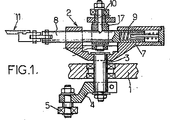
特許文献1に、移送アーム搬送装置の配置が示され、それについて説明されている(図6〜12;7ページ16行目〜8ページ15行目、10ページ20行目〜11ページ26行目)。添付図面の図1〜3を参照すると(フランス特許第2,479,077号公報の図8、10、11にそれぞれ対応)、この周知の搬送装置は複数の移送アーム2を担持する回転プレート1を備え、移送アーム2は回転プレート1の周縁全体にわたって規則的に分散されている。これらの移送アーム2は、それぞれに対応する旋回シャフト3によってプレート1に旋回可能に取り付けられる。各移送アーム2は、半径方向定位置から両側に旋回させるために、ローラ5を担持するレバー4に固定連結される。ローラ5は、閉じた曲線形状を有する固定カム6と相互作用し、それをたどる。
Patent Document 1 shows and describes the arrangement of the transfer arm transfer device (FIGS. 6-12; page 7, line 16 to page 8,
さらに、各移送アーム2は伸縮式に作られる。このために、各アーム2は、プレート1に対して旋回するようにシャフト3に固定連結された鐙7を備える。ロッド8が、鐙7に自在に摺動可能な形で取り付けられ、そのロッド8と鐙7の間に挟入されたばね9によって最小伸び位置に戻る。ロッド8は、ローラ10に固定連結され、ローラ10は、閉じた曲線輪郭で延在する固定カムと相互作用し、それをたどる。カム上に支承されたローラ10により、プレート1が回転する間、移送アーム2の長さがカムの輪郭の関数として変化する。
Furthermore, each
ロッド8は、その自由端で、容器を把持するためのペンチ11を支持し、ペンチ11は、ばね14によって互いに引き寄せられる2つの旋回顎12、13を備える。図示されている実施形態では、容器を容易に把持/解放できるようにばね14と対抗して作用する、顎12、13を開くための機構が設けられている。この機構はリンクロッド15を備え、リンクロッド15は、ペンチ11に対して旋回し、シャフト17の周りに旋回するように鐙7に取り付けられたレバー16に対しても旋回する。レバー16のもう一方の端部は、曲線軌道19を規定する固定カムの経路と相互作用するローラ18を支持する。
The rod 8 supports at its free end a
他の周知の装置には、顎を開く機構は設けられていない。この場合、顎による容器の把持/解放は、力を加えて行われる。 Other known devices are not provided with a jaw opening mechanism. In this case, the grasping / releasing of the container by the jaw is performed by applying force.
図3に、旋回シャフト3がたどる軌道が20で示されている。
In FIG. 3, the trajectory followed by the
上記の構造的配置と、様々なカムを適切な形にとることによって、この周知の装置を後述するように動かすことができる。これは添付図面の図3に略図で示されている(ここで、この装置の回転中心とカルーセルの回転中心を結び、2つの円形軌道の接触点Dを通過する直線が、基準軸線であるとみなされる)。図3には、プレート1が回転中における、単一の移送アーム2の様々な配置の概略図が示されている。
By taking the above-described structural arrangement and various cams into appropriate shapes, this known device can be moved as described below. This is shown schematically in FIG. 3 of the accompanying drawings (where the straight line connecting the rotation center of the device and the rotation center of the carousel and passing through the contact point D of the two circular tracks is the reference axis). It is regarded). FIG. 3 shows a schematic view of various arrangements of a
接触点Dより円形軌道の4分の1下流(搬送装置の回転方向に対し)の開始点の付近では、移送アーム2は、半径方向定位置に向かって進むように、つまりペンチ11を支持するアーム2の自由端がプレート1上のアーム2の旋回シャフト3より先行するように、カム6に係合するローラ5によって動かされて旋回するようになっている。同時に、ロッド8は、移送アーム2が鐙7に対して延在して最大長に達するように、対応するカムと係合するローラ10によって動かされる。このようにして、ペンチ11は、接触点Dの上流に位置する点D1で、接触点Dの上流側の金型軸線の軌道と略一致する。
In the vicinity of the start point that is one-fourth downstream of the circular orbit from the contact point D (relative to the rotation direction of the transfer device), the
次いで、ローラ5と10をそれぞれ案内する各カムが適切な形状をしているため、ロッド8が鐙7内に徐々に引き込まれると同時に、移送アーム2は半径方向定位置の方に徐々に運ばれる。プレート1上で旋回するためのアーム2のシャフト3が上記で定義した基準軸線と一致すると、移送アーム2は半径方向定位置に達する。アーム2の旋回シャフト3が基準軸線と一致する位置に達すると、アーム2の長さは最小まで収縮される。
Next, since each cam for guiding the
基準軸線を超えると、反転動作で、移送アーム2は、上流側に(回転方向に対して)旋回して、半径方向定位置から徐々に離れるようになっており、同時に、その長さが、ロッド8が鐙7から徐々に延在して増すようになっている。
When the reference axis is exceeded, the
この配置のために、ペンチ11は、金型の軸線と一致したままになるようになっており、所定の角度αの区域にわたってこの金型に伴って移動する。この角度αは、金型の可動部品が移動するのに必要な時間を見込みながら(入口では金型の閉じる時間、出口では開く時間を含む)、金型の可動部品と干渉することなく、予備成形物を金型内に導くのを可能にする(入口)、あるいは容器を金型から取り外す(出口)のに十分な大きさになっている。
Due to this arrangement, the
この基本構造の変形実施形態が、特定の出願で考案されている。具体的には、特許文献2に、2つの容器を同時に処理する2段キャビティをもつ金型と相互作用するための2段把持ペンチを備えた変形形態が記載されている。2段ペンチユニットは、移送アームの端部に、旋回可能に取り付けられている。他の適合形態が、特許文献3、特許文献4および特許文献5に示されている。
Variations of this basic structure are devised in certain applications. Specifically,
これらの周知の配置は、完全に満足のゆくものであり、上記の容器製造設備で現在用いられていることは事実である。 These known arrangements are completely satisfactory and it is true that they are currently used in the container manufacturing facility described above.
しかし、これらの配置は構造的に複雑である。例えば伸縮アームの構造の一部分として摺動部材を使用しており、これによって摩擦が生じ、したがって摩耗が生じる。この結果、振動および騒音が生じる遊びが徐々に発生する。さらに、可動部品を複数動かすには、それに対応するカムの設備が必要であるが、カムは製造が難しく、その数に応じたスペースを必要とする。 However, these arrangements are structurally complex. For example, a sliding member is used as part of the structure of the telescopic arm, which causes friction and therefore wear. As a result, play in which vibration and noise are generated gradually occurs. Further, in order to move a plurality of movable parts, it is necessary to provide a cam apparatus corresponding to the movable parts. However, it is difficult to manufacture the cam, and a space corresponding to the number of the cams is required.
とりわけ、上記のように設計された搬送装置は、大きな横寸法を有し、金型装置の入口に配置された装置自体が、設備全体として形成されたユニットから突出するので、搬送装置全体がますます厄介になる。 In particular, the transfer device designed as described above has a large lateral dimension, and since the device itself located at the entrance of the mold device protrudes from the unit formed as a whole facility, the entire transfer device is increased. It gets more and more troublesome.
最後に、部材の多様性と動作の多様性により、容器製造設備の使用者の間で、出力速度を高速にしたいという強い要求があっても、周知の搬送装置を現在使用されているものより高速で動かそうとすることが不可能なっている。
したがって、本発明の目的は、この産業の様々な要求に応じ、改良された搬送装置を提案することである。改良された搬送装置とは、所与の角度の区域にわたって金型に伴って移動することによって、予備成形物を送達する機能、または完成した容器を把持する機能を実現することが可能なまま、構成部材がより少なく可動部材がより少ない(カムの数が低減された)簡易化された構造を有し、よりコンパクトで、したがって全般に密度がより高い形で設備を製作することを可能にし、より速い動作速度をサポートすることができる装置である。 Accordingly, it is an object of the present invention to propose an improved transport device that meets the various requirements of this industry. The improved transport device remains capable of delivering the preform or gripping the finished container by moving with the mold over an area of a given angle, It has a simplified structure with fewer components and fewer moving members (reduced number of cams), making it possible to produce equipment in a more compact and therefore generally higher density form, It is a device that can support faster operating speeds.
こういった目的のために、上記の回転容器搬送装置は、本発明に従って設計されると、
旋回シャフトと主アームの自由端が、上記旋回シャフトの円形軌道に対して略接線方向に延在する線を規定し、旋回シャフトは、上記アームの自由端よりも、台の回転方向に先行すること、
曲線状のカムが、台の回転中、従動ローラによって駆動される上記主アームの端部が略半径方向に動くような構造になっていること、
主アームの上記自由端に取り付けられた把持ペンチが、台の固定された回転角度範囲にわたって所定の円形経路をたどり、上記円形経路の凸部が、回転台の軌道の反転形であることを特徴とする。
For these purposes, the rotating container transport device described above is designed according to the present invention,
The swivel shaft and the free end of the main arm define a line that extends in a substantially tangential direction with respect to the circular orbit of the swivel shaft, and the swivel shaft precedes the free end of the arm in the direction of rotation of the table. thing,
The curved cam is structured so that the end of the main arm driven by the driven roller moves in a substantially radial direction during the rotation of the table,
The gripping pliers attached to the free end of the main arm follow a predetermined circular path over a fixed rotation angle range of the base, and the convex part of the circular path is an inverted form of the trajectory of the rotary base. And
本発明に従って提案される配置により、移送アームは、摺動部材がない簡易な構造を有し、その動きはすべて純粋に回転のみになる。さらに、回転アームの移動機能は、そのプレート上への取付け軸線の周りの旋回にまで縮小され、その結果、この旋回運動は、互いに対向する2つの案内トラックを有する単一のカムと係合する単一の従動ローラによって作動させることができ、あるいは、ローラの跳ね返り現象を回避するために、2つの案内トラックが互いに向かい合って垂直方向にずれたカムと相互作用する、上下の2つのローラによって作動させることができる。 Due to the proposed arrangement according to the invention, the transfer arm has a simple structure with no sliding members, and all its movements are purely rotational. Furthermore, the movement function of the rotating arm is reduced to a pivot about its mounting axis on its plate, so that this pivoting movement engages a single cam with two guide tracks facing each other. Can be actuated by a single driven roller, or actuated by two upper and lower rollers with two guide tracks interacting with a vertically offset cam facing each other to avoid roller bounce Can be made.
移送アームがこのように設計されると、従来技術の配置に対して、把持ペンチは、上記の所定の回転角度αにわたって成形物の軸線に完全な共軸線の形で伴って移動することができなくなるとみなされている。ただし、金型の軸線とペンチの間の半径方向の差は、接触点Dの上流側で小さくなり、下流側で大きくなるが、実際には非常に小さく、一般に100分の数ミリメートルであり、あるいは最大でも10分の数ミリメートルであることに留意されたい。したがって、ペンチによって支持される容器と金型の壁の間が接触しないようにしながら、ペンチが金型の軸線に伴ってできるだけ近づいたまま移動することができる移送動作は、完全に実現可能である。つまり、ペンチは、厳密に金型の回転運動と共軸線に、その軸線に伴って移動することはないが(これにより、完全に、容器と金型の壁の間の接触がなくなるはずである)、半割りの金型と容器の間の最小安全距離を維持し、したがってその間が接触しないようにしながら、容器がこの半割りの金型の開閉動作に伴って移動するような軌道をたどるように動作させることが可能である。 When the transfer arm is designed in this way, with respect to the prior art arrangement, the gripping pliers can be moved in the form of a complete coaxial line to the axis of the molding over the predetermined rotation angle α described above. It is considered to disappear. However, the radial difference between the mold axis and the pliers decreases on the upstream side of the contact point D and increases on the downstream side, but is actually very small, generally a few hundredths of a millimeter, Note also that it is at most a few tenths of a millimeter. Therefore, a transfer operation in which the pliers can be moved as close as possible along the mold axis while preventing contact between the container supported by the pliers and the mold wall is completely feasible. . That is, the pliers do not move exactly along the axis of rotation and coaxial with the mold (which should completely eliminate the contact between the container and the mold wall) ), Keeping a minimum safe distance between the half mold and the container, so that there is no contact between them, so that the container follows a trajectory that moves as the half mold opens and closes It is possible to operate.
移送アームおよびその動作を構造的に簡略化した結果、搬送装置のコストが低減され、とりわけ、搬送装置を既存の装置よりかなり速い速度で動作させることができるようになり、この改良と組み合わせて、その他のリンクされた装置にも行われる因子により、容器製造設備全体をかなり速い速度で動作させることが可能になることは明らかである。 As a result of the structural simplification of the transfer arm and its operation, the cost of the transport device is reduced, in particular the transport device can be operated at a much faster speed than existing devices, combined with this improvement, Obviously, factors that are also applied to other linked devices allow the entire vessel manufacturing facility to operate at a much faster speed.
把持ペンチの略半径方向の動作中の搬送装置の横寸法をある程度縮小するために、好ましい実施形態では、
移送アームの主アームは、略L字形になっており、一方の端部が上記回転台上に上記旋回シャフトによって取り付けられた第1の枝と、上記第1の枝に対して略長手方向に直角な横方向に延在する第2の枝とを備え、
上記第1の枝が、その自由端で、上記第2の枝に対して略長手方向に直角な横方向に延在する上記把持ペンチを支持する。
In order to reduce to some extent the lateral dimension of the conveying device during movement in the substantially radial direction of the gripping pliers,
The main arm of the transfer arm is substantially L-shaped, one end of which is attached to the rotary base by the pivot shaft, and a substantially longitudinal direction with respect to the first branch. A second branch extending in a transverse direction at right angles,
The first branch supports, at its free end, the gripping pliers extending in a lateral direction substantially perpendicular to the longitudinal direction with respect to the second branch.
後者の場合における実施可能性は、従動ローラを主アームの第2の枝に固定連結することにある。この場合、従動ローラを、主アームの第2の枝に対して第1の枝と反対側の長手方向に略直角な横方向に延在するレバーアームで支持すると有用である。具体的には、第1の枝および把持ペンチを第2の枝の同じ側から延ばし、レバーアームをその反対側から延ばすことが可能である。この配置により、台の把持具が減り、アームをずらすことが可能になる。 The feasibility in the latter case consists in fixedly connecting the driven roller to the second branch of the main arm. In this case, it is useful to support the driven roller with a lever arm extending in a lateral direction substantially perpendicular to the longitudinal direction opposite to the first branch with respect to the second branch of the main arm. Specifically, it is possible to extend the first branch and gripping pliers from the same side of the second branch and the lever arm from the opposite side. With this arrangement, the gripping tool of the base is reduced and the arm can be shifted.
実際的な面から、実施形態の具体的な例では、主アームの第1および第2の枝は、その間に、90°を超える角度(100°〜110°の範囲)を形成するようになっている。 From a practical standpoint, in a specific example of an embodiment, the first and second branches of the main arm will form an angle between them that exceeds 90 ° (range of 100 ° to 110 °). ing.
他の実施形態の具体的な例では、ペンチは、主アームの上記第2の枝に対して、90°を超える角度(95°〜110°の範囲)を向くようになっている。 In a specific example of another embodiment, the pliers are oriented at an angle greater than 90 ° (in the range of 95 ° to 110 °) with respect to the second branch of the main arm.
回転台は、プレートと、少なくとも1つの支持アームとを備え、支持アームは、上記プレートに固定連結され、上記プレートに対して略半径方向に延在し、この支持アームの端部は、移送アームの旋回シャフトを支持するのが好ましい。 The turntable includes a plate and at least one support arm, and the support arm is fixedly connected to the plate and extends in a substantially radial direction with respect to the plate, and an end of the support arm has a transfer arm. The pivot shaft is preferably supported.
周知の簡単な方法によって、ペンチは、ばねによって自動的に閉位置まで戻るタイプのものになるようになっている。 By a well-known simple method, the pliers are of the type that automatically returns to the closed position by a spring.
振動および騒音を発生させるはずの跳ね返り現象なしでアームが正確に案内されるようにするために、この装置は、互いにずれた2つのカム、すなわち内側カム、外側カムとそれぞれ相互作用する、上下に重なる2つのアイドルローラを有することが望ましい。 In order to ensure that the arm is guided accurately without the bounce phenomenon that should generate vibration and noise, this device works up and down, interacting with two cams that are offset from each other: the inner cam and the outer cam, respectively. It is desirable to have two idle rollers that overlap.
以下のいくつかの好ましい実施形態の詳細な説明は、添付の図面を参照して行う。この説明を読めば、本発明はいっそう容易に理解されよう。これらの実施形態は単なる例として提示される。 The following detailed description of some preferred embodiments is made with reference to the accompanying drawings. The present invention will be more readily understood after reading this description. These embodiments are presented as examples only.
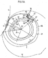
最初に図4Aを参照すると、本発明による搬送装置は、回転台21(従来技術装置の回転プレート1に対応)を有し、回転台21は、垂直軸線23の周りを回転する回転プレート22を備えていることが有利である。
Referring first to FIG. 4A, the transport device according to the present invention has a turntable 21 (corresponding to the turntable 1 of the prior art device), and the
プレート22は、後述のように設計された、少なくとも1つの可動組立体25(実際には複数の組立体)を支持する。主アーム26が、垂直シャフト27によってプレート22上に旋回可能に支持され、プレート22の平面に略平行な水平面で旋回することができる。把持ペンチ30が、主アーム26の自由端に取り付けられ、アーム26に対して長手方向に略直角な横方向に延在する。最後に、少なくとも1つの自在に回転する従動ローラ32が、主アーム26に固定連結され、軸線23の周りで閉じた曲線の輪郭を有する固定カム33と相互作用する。ローラ32は、主アーム26に対して横向きのレバーアーム31の端部に取り付け、それに固定連結してもよい。
The
本発明によれば、旋回シャフト27と、主アーム26の自由端は、上記旋回シャフト27の円形軌道に対して略接線方向に延在する線Lを規定するようになっており、旋回シャフト27は、台21の回転方向(矢印F)に、アーム26の自由端より先行し、したがって把持ペンチ30より先行する。
According to the present invention, the
曲線状のカム33はまた、台21の回転中、把持ペンチ30を装備した、従動ローラ32によって駆動される上記主アーム26の自由端が、略半径方向に動くような構造になっている。
The
最後に、主アーム26の上記自由端に取り付けられた把持ペンチ30はまた、台21の固定された回転角度範囲αにわたって、凸部が回転台21の軌道に対して反転している(つまり図4Aに示す外向きの凹部)、所定の円形の経路をたどるようになっている。
Finally, the gripping
次に、上記の搬送装置の好ましい変形形態を示す図4Bを参照する。この変形形態では、回転台21は、垂直軸線23の周りに回転する回転プレート22を備え、回転プレート22は、かなり小さい直径を有し、複数の固定された半径方向アーム24を備える(例えば、図示した例では角度が60°ずつ、ずれた5本のアーム24)。例としては、アーム24の長さはプレート22の半径と略等しくなっている。この配置により、一方で、従来技術の装置より、あるいは前述の装置よりも回転部分をかなり軽くすることが可能になり、その一方で、後述の各可動組立体を、垂直回転軸線23から半径方向に過度にずらすことなく動かすことができるように、2つの連続する可動組立体同士の間に空き間隔を設けることが可能になる。
Reference is now made to FIG. 4B which shows a preferred variant of the transport apparatus described above. In this variant, the
各半径方向アーム24は、後述のように設計された可動組立体25を支持する。前述の場合と同様に、主アーム26は、半径方向アーム24の端部で垂直シャフト27によって旋回可能に支持される。この場合、主アーム26は、略L字形になっており、一方の端部が回転台21の半径方向アーム24の端部にシャフト27によって取り付けられた第1の枝28と、上記第1の枝28に対して長手方向に略直角な横方向に延在する第2の枝29と、を備える。さらに、把持ペンチ30が、主アーム26の第2の枝29の自由端に取り付けられ、第2の枝29に対して長手方向に略直角な横方向に延在する。
Each
最後に、レバーアーム31が、一方の端部で主アーム26の第2の枝29に固定連結され、そのもう一方の端部で少なくとも1つの従動ローラ32を支持するのが好ましい。
Finally, the
図5に示されているように、ローラ32が単独である場合の跳ね返り現象を回避するために、2つのローラ32a、32bが、それぞれ2つのカム33i、33eと相互作用するように設けられていることが有利である。2つのカム33i、33eは互いに対向し、垂直方向にずれ、カム33iは内側に位置し、もう一方のカム33eは外側に位置して案内溝を形成する。
As shown in FIG. 5, two
回転組立体の半径方向の寸法をできるだけ縮小するために、上記主アーム26の第1の枝28が、旋回シャフト27から略内向きにプレート22の方に延在するように、可動組立体25が大部分半径方向アーム24に沿って収容され、半径方向アーム24の端部を超えて半径方向に実質上延在しないように、略L字形の主アーム26は半径方向アーム24に固定される。したがって、この文脈では、上記線Lは主アーム26と一致せず、主アーム26はこの線に対して内向き半径方向に引き込まれる。
In order to reduce the radial dimension of the rotating assembly as much as possible, the
把持ペンチ30が、第1の枝28と同じ側で第2の枝29に対して長手方向に略直角な横方向に延在するように、第2の枝29に取り付けられ、この組立体が略U字形をしていることにも留意されたい。取付けと動作を容易にするために、主アームの第1、第2の枝28、29は互いに直交せず、その間に90°を超える角度を形成する(100°〜110°の範囲が好ましい)。同様に、把持ペンチ30は、第2の枝29と、90°を超える角度を形成する(95°〜110°の範囲が好ましい)。
A gripping
レバーアーム31については、カム33が回転軸線23に対して比較的小さな延長半径(可変)を有するように、第2の枝29の、第1の枝28と把持ペンチ30の反対側に取り付けられる。
The
把持ペンチ30は、その機能に適した任意の方法で構成できることを重視されたい。
It should be emphasized that the gripping
図4A、図4Bおよび図5に示されているように、カムおよびローラで開く、および/または、閉じる複雑な動作を避けるために、図2に示されているペンチのタイプが使用されていることが有利である。このペンチは、対向する力がないときは、戻しばね34によって顎35が閉位置まで戻るが、カム33内で移動するローラ32によって駆動される主アーム26の押す、または引く作用を受けると、開いて容器の首と接触する。
As shown in FIGS. 4A, 4B and 5, the type of pliers shown in FIG. 2 is used to avoid the complex movement of opening and / or closing with cams and rollers. It is advantageous. When there is no opposing force, the
これまで説明した手段により、カム33に、回転軸線23に対して必要な形を与えて、ローラ32を適切に案内することによって、把持ペンチ30を所望の任意半径方向に位置決めすることが可能になる。
By the means described so far, it is possible to position the gripping
図4Aおよび図4Bでは、把持ペンチ30がたどる軌道は、回転軸線23の周りの旋回シャフト27の回転運動と、カム33におけるローラ32の回転と半径方向運動の組合せ運動とを組み合わせた結果として、T字形になっている。角度区域αでは、容器を交換(回収または送達)する装置(例えば金型)の軸線がたどる凸形の曲線軌道Vを、軌道Tがたどることに留意されたい。
In FIG. 4A and FIG. 4B, the trajectory followed by the gripping
図4Aおよび図4Bを参照すると、従来技術の装置よりもはるかに簡易な構造によって、ペンチ30の軌道Tが、所望の角度区域にわたって軌道Vをたどることが可能になるだけでなく、このペンチ30の軌道Tの、軸線23周りの半径方向の延長を従来技術の装置のペンチのものより(比較のためにWで示す)はるかに小さくすることが可能になることに留意されたい。したがって、従来技術の装置よりもはるかに小さい搬送装置が形成され、その結果、より一般的には、容器製造設備に占める設置面積が小さくなる。
Referring to FIGS. 4A and 4B, a much simpler structure than prior art devices not only allows the trajectory T of the
ここで説明した回転台21を備えた特有の構造と、対応する半径方向アーム24の端部に設けられた可動組立体25にもたらされる簡易構造によって、回転組立体がかなり軽くなり、その結果慣性が小さくなることも重視されたい。さらに、各可動組立体25の唯一の動きは、従来技術の装置の回転運動と並進運動の複合の代わりに、主アーム26の旋回運動であり、この単一の旋回運動に必要なのは、従来技術の装置の複数のカムの代わりに、単一のカムだけである。この結果、回転台21を駆動するための摩擦および抵抗が小さくなり、占めるスペースが小さくなる。
The unique structure with the
最後に、この、より軽く抵抗が小さくなった装置の回転速度は、従来技術の装置で実現できる速度よりもかなり速くすることが可能であり、それによって、他の関連装置で行われるその他の配置と組み合わせて、この完成した設備に対してより高い生産速度を提案することが可能になる。さらに、この著しい利点には、本発明による装置製造コストのかなりの低減が伴う(構成部品数が減ったための、原材料の低減、部品機械加工コストの低減、組立/取付けコストの低減)。 Finally, the rotational speed of this lighter, less drag device can be significantly faster than can be achieved with prior art devices, thereby allowing other arrangements to be made with other related devices. In combination, it is possible to propose a higher production rate for this completed equipment. Furthermore, this significant advantage is accompanied by a considerable reduction in the device manufacturing costs according to the invention (reduced raw materials, reduced component machining costs, reduced assembly / installation costs due to the reduced number of components).
ここで、構造が簡略化された搬送装置が、従来技術の搬送装置と同じ全機能を実施するためのものとみなされていることについて触れる必要がある。その機能とはすなわち、把持装置(ペンチ)が、所定の角度区域にわたって、自身のたどる軌道に対して(ペンチは、その軌道まで容器を送達する、あるいはその軌道から容器を回収する)凸形の円形軌道をたどる器具に伴って移動するように動作する機能のことである。しかし、所望の機能は、本発明による装置による全般的な機構において確かに行われるが、本発明による装置の動作は、単なる簡略化した構造を使用した従来技術装置とは詳細がかなり異なる。 It should be mentioned here that the transport device with a simplified structure is considered to carry out all the same functions as the transport device of the prior art. Its function is that the gripping device (pliers) is convex over a predetermined angular area with respect to its trajectory that it follows (the pliers deliver the container to or retrieve the container from the trajectory). It is a function that operates so as to move with an instrument that follows a circular orbit. However, although the desired function is certainly performed in the overall mechanism by the device according to the invention, the operation of the device according to the invention is quite different in detail from the prior art devices using only a simplified structure.
これは、上述したように、従来技術の装置の設計は、ペンチが、関連装置に設けられた容器支持体の軸線(例えば金型の軸線)と厳密に共軸線のまま、所与の角度区域にわたってその関連装置を伴うようになっていたからである。上記の複雑な移送アーム設計を招いたのは、この角度区域にわたる共軸線性の維持であるが、実際に達成する所望の目的は、ペンチによって送達または回収される容器と、関連装置(例えば金型の壁)の間の干渉を避けることである。 This is because, as mentioned above, the design of the prior art device is such that the pliers remain strictly coaxial with the axis of the container support (eg the mold axis) provided in the associated device, for a given angular area. It was because it came to be accompanied by the related device. It was the maintenance of coaxiality over this angular area that led to the complex transfer arm design described above, but the desired objectives to be achieved in practice are the containers delivered or retrieved by pliers and associated devices (e.g. gold To avoid interference between the mold walls).
従来技術の装置とは異なった方法で動作するので、本発明による、図4A、図4Bおよび図5を参照して上記で説明した可動組立体25の簡略化された構造では、厳密な共軸線性を角度区域全体にわたって維持することはできない。この角度区域の開始および終了領域では、ペンチの軸線が、関連装置のハウジングの軸線に対してわずかにずれ、軌道が一致する角度区域の中心部分でのみ厳密な共軸線性が実現される。しかし、この差は非常に小さく、10分の数ミリメートル程度のものであり、実際には、このために問題は生じないことが指摘されよう。関連装置がブックタイプの金型である場合、本発明に従って設計された搬送装置のペンチにより送達または回収される容器は、半割りの金型の一方の、それぞれ閉じるまたは開く動作に伴って移動するが、その金型と接触することはない。
The simplified structure of the
より低コストであることと、より速い動作速度という異なった要件を満たすことができる、簡略化された構造を備えた移送アームの設計を可能にするのはまさに、共軸線性が必ずしも不可欠だとは限らない軌道の領域で、動作中の関連装置のハウジングに対する上述のペンチのずれを受け入れることに他ならない。 Coaxiality is always essential to enable the design of transfer arms with a simplified structure that can meet the different requirements of lower cost and faster operating speed. In the region of the trajectory which is not limited, it is none other than accepting the above-mentioned pliers displacement relative to the housing of the associated device in operation.
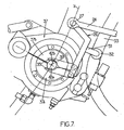
例として、この点に関して、添付図面の図6〜図8に、本発明による回転式カルーセル36に対する搬送装置動作が拡大図で示されている。回転式カルーセル36は、その周縁部で、熱変形可能な樹脂、具体的にはPETから容器(この場合にはボトル)を製造するための多数のブロー成形金型または延伸ブロー成形金型37を支持する。 By way of example, in this regard, FIGS. 6-8 of the accompanying drawings show, in an enlarged view, the operation of the transport device for a rotary carousel 36 according to the present invention. The rotary carousel 36 has a number of blow molding dies or stretch blow molding dies 37 for manufacturing a container (in this case, a bottle) from a heat-deformable resin, specifically, PET, at the peripheral portion thereof. To support.
最初に図6および図7を参照すると、完成した容器が、把持ペンチ30によって金型から回収される3ステップが示されている。各金型37は、2つの半割りの金型37a、37bが旋回シャフト38で接合されたブックタイプのものであるものとする。金型37の軸線39は、円形の線Vで示される円形の軌道をたどる。
Referring initially to FIGS. 6 and 7, three steps are shown in which the completed container is retrieved from the mold by gripping
図6では、図面下部の金型37が閉じた配置にある。容器40が、ブロー成形または延伸ブロー成形によってそこに成型されたところである。金型から突出する容器の首41のみ見えている。ここでは、容器は金型と共軸線である。搬送装置は、適切な形のカム33で案内されたローラ32によって押し動かされる主アーム26の作用で、ペンチ30が外向き半径方向に動く(軸線23に対して)ような、位置にあり、ここには、容器の首41と接触するところが示されている。
In FIG. 6, the
ペンチ30の半径方向外向きの動きが続くので、ペンチ30が首41に接触して開き、顎35が首の両側を通過し、次いでばね34の作用で弾性的に閉じて、容器40の首41を固定する。
As the radially outward movement of the
このとき、容器40が搬送装置によって回収された場合は、図7に拡大図で示すように金型37が部分的に開き始める。(図7では容器の首41は示されていない。半割りの金型37a、37bの2つの中心の、図6の下部では金型37内で首41を取り囲んでいた半割り空洞42a、42bを、この時点で容器の首を間に把持しているペンチ30の2つの顎35と一緒に確認し易くするため)。図7に示されている金型37が最初に開く位置では、ペンチ30の顎35の軸線、つまり容器の軸線は金型の軸線39とまだ一致しており、ペンチ30は線Vに沿って金型37の軸線39に伴って移動する。
At this time, when the container 40 is collected by the transport device, the
図8には、金型37がさらに開いた、その後の状況が示されている(ただしまだ完全には開いていない)。ペンチ30の顎35の軸線43は(したがってそれによって支持された容器の軸線も)まだ、金型37の軸線39がたどる軌道V上にあるが、非常に小さなずれが顎35の軸線43と金型の軸線39の間に現れ始め、軸線43が軸線39に対してわずかに遅れ始める。
FIG. 8 shows the situation after the
最後に、図6の上側に示されている状況では、主アーム26はすでに半径方向にかなり離れて、容器40が金型との係合を解除する段階である一方、金型37は最大限に開いた位置になる。顎35の軸線43は(したがって容器40の軸線も)もう金型37の軸線39の位置と合っていないが、金型37の軸線39からかなり遅れ、それによって容器40は半割りの金型37aの壁に可能な限り近づいてついていくが、その壁に接触することはないことが指摘されよう。
Finally, in the situation shown on the upper side of FIG. 6, the
図9には、容器(ここでは例えば予備成形物)を金型37に送達する2つのステップが示されている。図9の下側では、ペンチ30が首41で予備成形物44を支持し、予備成形物44の軸線43が軌道Tをたどる一方、金型37が最大限度まで開いて、軸線39が円形軌道Vをたどっている。図9の上側では、2つの軌道TとVが一致し、ペンチ30と予備成形物44が再び閉じた金型37と共軸線にある。そのすぐ下流で、2つの軌道TとVが、カム33によって案内されるローラ32によってそれ自体が駆動される主アーム26の駆動力を受けて互いに離れていく。ペンチ30は半径方向外向きに押し動かされ、予備成形物44の首41との係合を解除され、次いで予備成形物44の首41が金型37によって支持される。
FIG. 9 shows two steps for delivering a container (here, for example, a preform) to the
主アーム26が容器を回収する機能を行う場合(図6〜8)、容器の軸線(つまり金型の軸線39)とペンチ(顎の軸線43)の位置は、2つの軌道TとVの正確な一致点、すなわちペンチが容器を把持する点で厳密に一致するようになっている必要があることに留意されたい。ただしその後は、相対的な配置の精度は必要ない。逆に、主アーム26が容器を送達する機能を行う場合(図9)、容器の軸線の位置(つまりペンチ顎30の軸線)と開いた金型の軸線の位置は、2つの軌道TとVの正確な一致点、すなわちペンチが容器を解放する点で厳密に一致するようになっている必要がある。ただしその前は、相対的な配置の精度は必要ない。
When the
21 回転台
22 回転プレート
23 垂直軸線
24 半径方向アーム
25 可動組立体
26 主アーム
27 垂直シャフト
28 第1の枝
29 第2の枝
30 把持ペンチ
31 レバーアーム
32 従動ローラ
32a ローラ
32b ローラ
33 固定カム
33i カム
33e カム
34 戻しばね
35 顎
37 金型
37a 半割りの金型
37b 半割りの金型
38 旋回シャフト
39 金型の軸線
40 容器
41 容器の首
42a 半割り空洞
42b 半割り空洞
43 顎の軸線
44 予備成形物
21 rotating table 22 rotating
Claims (10)
旋回シャフト(27)によって前記台(21)に旋回可能に取り付けられた主アーム(26)であって、前記旋回シャフト(27)と、主アーム(26)の自由端と、が該旋回シャフトの円形軌道に対して略接線方向に延在する線(L)を規定し、該旋回シャフトが、前記アームの自由端よりも、前記台(21)の回転方向(F)に先行している、前記主アーム(27)と、
前記主アーム(26)の自由端に取り付けられた把持ペンチ(30)と、
前記主アーム(26)に固定連結され、かつ、閉じた輪郭に沿って延在する、固定された曲線状のカム(33)に追従することによって相互作用することができる、少なくとも1つの自在に回転するローラ(32)と、を備え、
前記台(21)の回転中、前記主アーム(26)の前記自由端に取り付けられた前記把持ペンチ(30)が、前記台(21)が回転する、固定された回転角度範囲(α)にわたって所定の円形経路を追従し、前記円形経路の凸部が前記回転台(21)の軌道の逆形であるように、前記曲線状のカム(33)が形状構成されている回転装置において、
前記把持ペンチ(30)は、該把持ペンチ(30)が前記主アーム(26)に対して長手方向に略直角な方向に延在するように、該主アーム(26)の自由端に取り付けられ、及び、
前記台(21)の回転中、前記カム(33)と相互作用して追従する前記ローラ(32)によって駆動される前記主アーム(26)の自由端に取り付けられた前記把持ペンチ(30)が略半径方向に旋回させることによって動くようになっていることを特徴とする装置。A rotating device for transporting a container, comprising a turntable (21) continuously rotating around an axis of rotation (23) and supporting at least one movable assembly (25),
A main arm (26) pivotably attached to the table (21) by a pivot shaft (27), wherein the pivot shaft (27) and a free end of the main arm (26) are connected to the pivot shaft. Defining a line (L) extending in a substantially tangential direction with respect to the circular orbit, wherein the pivot shaft precedes the rotational direction (F) of the platform (21) rather than the free end of the arm; The main arm (27) ;
Gripping pliers (30) attached to the free end of the main arm (26);
At least one freely capable of interacting by following a fixed curved cam (33) fixedly connected to the main arm (26) and extending along a closed profile e Bei roller rotating (32), a
During the rotation of the platform (21), the gripping pliers (30) attached to the free end of the main arm (26) are moved over a fixed rotation angle range (α) in which the platform (21) rotates. In the rotating device in which the curved cam (33) is shaped so as to follow a predetermined circular path and the convex part of the circular path is a reverse shape of the orbit of the turntable (21) ,
The gripping pliers (30) are attached to the free end of the main arm (26) such that the gripping pliers (30) extend in a direction substantially perpendicular to the longitudinal direction of the main arm (26). ,as well as,
The gripping pliers (30) attached to the free end of the main arm (26) driven by the roller (32) that interacts and follows the cam (33) during rotation of the platform (21). and wherein that you have made to move by pivoting in a generally radial direction.
略L字形になっており、一方の端部が前記回転台(21)上に前記旋回シャフト(27)によって取り付けられた第1の枝(28)と、
該第1の枝(28)に対して長手方向に略直角な横方向に延在する第2の枝(29)と、を備え、
前記第1の枝(28)が、その自由端で、前記第2の枝(29)に対して長手方向に略直角な横方向に延在する前記把持ペンチ(30)を支持することを特徴とする、請求項1に記載の装置。The main arm (26) of the movable assembly (25);
A first branch (28) that is substantially L-shaped, one end of which is mounted on the turntable (21) by the pivot shaft (27);
A second branch (29) extending in a transverse direction substantially perpendicular to the longitudinal direction with respect to the first branch (28),
The first branch (28) supports, at its free end, the gripping pliers (30) extending in a lateral direction substantially perpendicular to the longitudinal direction with respect to the second branch (29). The apparatus according to claim 1.
Applications Claiming Priority (3)
| Application Number | Priority Date | Filing Date | Title |
|---|---|---|---|
| FR0501265 | 2005-02-08 | ||
| FR0501265A FR2881677B1 (en) | 2005-02-08 | 2005-02-08 | ROTARY DEVICE FOR TRANSFERRING CONTAINERS |
| PCT/FR2006/000280 WO2006084990A1 (en) | 2005-02-08 | 2006-02-07 | Rotary device for transferring containers |
Publications (2)
| Publication Number | Publication Date |
|---|---|
| JP2008529920A JP2008529920A (en) | 2008-08-07 |
| JP4722947B2 true JP4722947B2 (en) | 2011-07-13 |
Family
ID=34954523
Family Applications (1)
| Application Number | Title | Priority Date | Filing Date |
|---|---|---|---|
| JP2007553663A Expired - Fee Related JP4722947B2 (en) | 2005-02-08 | 2006-02-07 | Rotating device for transferring containers |
Country Status (11)
| Country | Link |
|---|---|
| US (1) | US7543697B2 (en) |
| EP (1) | EP1846218B1 (en) |
| JP (1) | JP4722947B2 (en) |
| CN (1) | CN101137491B (en) |
| AT (1) | ATE399086T1 (en) |
| DE (1) | DE602006001576D1 (en) |
| ES (1) | ES2309949T3 (en) |
| FR (1) | FR2881677B1 (en) |
| MX (1) | MX2007009536A (en) |
| PT (1) | PT1846218E (en) |
| WO (1) | WO2006084990A1 (en) |
Families Citing this family (32)
| Publication number | Priority date | Publication date | Assignee | Title |
|---|---|---|---|---|
| US7810629B2 (en) * | 2004-02-02 | 2010-10-12 | Krones Ag | Device for dynamic storage of objects |
| DE202004016069U1 (en) | 2004-10-16 | 2005-12-01 | Krones Ag | Device for buffering objects |
| DE202005013552U1 (en) | 2005-08-27 | 2005-11-03 | Krones Ag | Dynamic storage for buffering and transporting empty bottle, has lower deflection pulleys rotating in essentially horizontal planes and connected with vertical loops by curved guides for conveyor chain |
| FR2895384B1 (en) * | 2005-12-26 | 2009-10-30 | Sidel Sas | DEVICE FOR SELECTIVELY TRANSFERRING ARTICLES WITH LARGE CADENCE, APPLICATION FOR SORTING BOTTLES, BLOWING MACHINE COMPRISING SUCH A DEVICE |
| DE102006008123A1 (en) * | 2006-02-20 | 2007-08-23 | Krones Ag | Dynamic conveyor holding zone, for items being carried, has two conveyor paths moving in opposite directions with a transfer unit to move them from one to the other and a control unit linked to sensors |
| DE102006012148A1 (en) * | 2006-03-16 | 2007-09-20 | Krones Ag | funding |
| DE102006035109A1 (en) * | 2006-07-29 | 2008-01-31 | Krones Ag | Conveyor device for use in bottle handling device, has conveyors separated from each other and connected with buffer over transferring points, where intermediate conveyor bypasses buffer |
| US7740125B2 (en) * | 2006-12-29 | 2010-06-22 | The Gillette Company | Component feeding with continuous motion escapement |
| IT1391818B1 (en) * | 2008-11-13 | 2012-01-27 | Mbf Spa | EQUIPMENT FOR THE TRANSFER OF CONTAINERS |
| DE102010033749B4 (en) * | 2010-08-07 | 2012-02-16 | Mall + Herlan Gmbh | Device for processing workpieces |
| DE102010049029A1 (en) * | 2010-10-21 | 2012-04-26 | Krones Aktiengesellschaft | Apparatus and method for treating plastic containers with a constant pitch |
| US8833542B2 (en) | 2012-04-16 | 2014-09-16 | The Procter & Gamble Company | Fluid systems and methods for transferring discrete articles |
| US8720666B2 (en) | 2012-04-16 | 2014-05-13 | The Procter & Gamble Company | Apparatuses for transferring discrete articles |
| US8607959B2 (en) | 2012-04-16 | 2013-12-17 | The Procter & Gamble Company | Rotational assemblies and methods for transferring discrete articles |
| US8820513B2 (en) | 2012-04-16 | 2014-09-02 | The Procter & Gamble Company | Methods for transferring discrete articles |
| DE102012017048B4 (en) * | 2012-08-29 | 2016-09-15 | Khs Gmbh | Container and transport device with self-adaptive gripping elements and method for cross-transport of containers to a treatment and transport device |
| ITPR20120067A1 (en) * | 2012-10-17 | 2014-04-18 | Lanfranchi Srl | ROTATING SYSTEM FOR THE TRANSFER OF BOTTLES OR CONTAINERS IN GENERAL |
| US20140110052A1 (en) | 2012-10-23 | 2014-04-24 | The Procter & Gamble Company | Methods for transferring discrete articles onto a web |
| CN103029992B (en) * | 2013-01-11 | 2015-04-29 | 广州华工环源绿色包装技术有限公司 | Rotary transfer stacking device |
| WO2014167369A1 (en) * | 2013-04-10 | 2014-10-16 | Inman S.R.L. | Apparatus and process for transferring and rotating an object |
| US9463942B2 (en) | 2013-09-24 | 2016-10-11 | The Procter & Gamble Company | Apparatus for positioning an advancing web |
| JP6140125B2 (en) * | 2014-02-04 | 2017-05-31 | 東洋自動機株式会社 | Bag transfer device |
| JP6140086B2 (en) * | 2014-02-06 | 2017-05-31 | 東洋自動機株式会社 | Bag transfer device |
| US9783375B2 (en) | 2014-08-12 | 2017-10-10 | Kaufman Engineered Systems, Inc. | Lane forming apparatus |
| DE102015005457A1 (en) * | 2015-04-30 | 2016-11-03 | Khs Corpoplast Gmbh | Rotor of a device for molding and / or filling containers from preforms |
| US9511952B1 (en) | 2015-06-23 | 2016-12-06 | The Procter & Gamble Company | Methods for transferring discrete articles |
| US9511951B1 (en) | 2015-06-23 | 2016-12-06 | The Procter & Gamble Company | Methods for transferring discrete articles |
| ITUB20152731A1 (en) * | 2015-07-31 | 2017-01-31 | Ave Tech S R L | EQUIPMENT FOR HANDLING CONTAINERS |
| DE102017112220A1 (en) * | 2017-06-02 | 2018-12-27 | Khs Gmbh | Apparatus and method for transporting containers |
| CN108529221A (en) * | 2018-01-30 | 2018-09-14 | 东莞市圣荣自动化科技有限公司 | A kind of horizontally adjustable electromagnet type rotating mechanism of auto parts machinery plate body |
| DE102018126797A1 (en) * | 2018-10-26 | 2020-04-30 | Khs Corpoplast Gmbh | Pliers for holding workpieces, especially preforms or containers |
| DE102022122525A1 (en) * | 2022-09-06 | 2024-03-07 | Krones Aktiengesellschaft | Device for following an actuation curve |
Citations (6)
| Publication number | Priority date | Publication date | Assignee | Title |
|---|---|---|---|---|
| US2609946A (en) * | 1947-05-14 | 1952-09-09 | American Can Co | Feeding mechanism with gripping device |
| US3659694A (en) * | 1969-09-05 | 1972-05-02 | Molins Machine Co Ltd | Packing or wrapping machine of the mould wheel type |
| FR2479077A1 (en) * | 1980-03-26 | 1981-10-02 | Pont A Mousson | INSTALLATION FOR MANUFACTURING HOLLOW BODIES THROUGH PACKAGING THEN BLOWING PREFORMS OF PLASTIC MATERIAL |
| JPS59230919A (en) * | 1983-06-10 | 1984-12-25 | Tenchi Kikai Kk | Apparatus for transferring wrapped article from article feeder means to rotary clamping portion |
| JPH04154140A (en) * | 1990-10-18 | 1992-05-27 | Tesetsuku:Kk | Automatic inspection apparatus of electronic component provided with parallel leads |
| WO2005007378A1 (en) * | 2003-07-14 | 2005-01-27 | Toyo Seikan Kaisya, Ltd. | Method and device for forcibly inserting drop into compression molding machine, and molding die follow-up type method and device for supplying drop |
Family Cites Families (6)
| Publication number | Priority date | Publication date | Assignee | Title |
|---|---|---|---|---|
| US2366615A (en) * | 1942-10-28 | 1945-01-02 | Hansen Kristian | Rotary transfer assembly |
| GB1522596A (en) * | 1974-10-15 | 1978-08-23 | Hauni Werke Koerber & Co Kg | Production of filter plugs |
| IT1188972B (en) * | 1980-12-12 | 1988-01-28 | Gd Spa | TRANSFER DEVICE FOR BAR-SHAPED ITEMS |
| IT1285515B1 (en) * | 1996-02-05 | 1998-06-08 | Azionaria Costruzioni Acma Spa | HANDLING UNIT FOR PRODUCTS |
| FR2802191B1 (en) * | 1999-12-13 | 2002-03-01 | Sidel Sa | DEVICE FOR CONVEYING DISCRETE ENTITIES INCLUDING AN IMPROVED TRANSFER ARM AND INSTALLATION FOR BLOWING CONTAINERS PROVIDED WITH SUCH A DEVICE |
| ITBO20020221A1 (en) * | 2002-04-23 | 2003-10-23 | Azionaria Costruzioni Acma Spa | PRODUCT TRANSFER WHEEL ALONG A WRAPPING LINE |
-
2005
- 2005-02-08 FR FR0501265A patent/FR2881677B1/en not_active Expired - Fee Related
-
2006
- 2006-02-07 ES ES06709268T patent/ES2309949T3/en active Active
- 2006-02-07 US US11/883,638 patent/US7543697B2/en not_active Expired - Fee Related
- 2006-02-07 MX MX2007009536A patent/MX2007009536A/en active IP Right Grant
- 2006-02-07 EP EP06709268A patent/EP1846218B1/en not_active Not-in-force
- 2006-02-07 WO PCT/FR2006/000280 patent/WO2006084990A1/en active IP Right Grant
- 2006-02-07 DE DE602006001576T patent/DE602006001576D1/en active Active
- 2006-02-07 JP JP2007553663A patent/JP4722947B2/en not_active Expired - Fee Related
- 2006-02-07 AT AT06709268T patent/ATE399086T1/en not_active IP Right Cessation
- 2006-02-07 PT PT06709268T patent/PT1846218E/en unknown
- 2006-02-07 CN CN2006800078921A patent/CN101137491B/en not_active Expired - Fee Related
Patent Citations (6)
| Publication number | Priority date | Publication date | Assignee | Title |
|---|---|---|---|---|
| US2609946A (en) * | 1947-05-14 | 1952-09-09 | American Can Co | Feeding mechanism with gripping device |
| US3659694A (en) * | 1969-09-05 | 1972-05-02 | Molins Machine Co Ltd | Packing or wrapping machine of the mould wheel type |
| FR2479077A1 (en) * | 1980-03-26 | 1981-10-02 | Pont A Mousson | INSTALLATION FOR MANUFACTURING HOLLOW BODIES THROUGH PACKAGING THEN BLOWING PREFORMS OF PLASTIC MATERIAL |
| JPS59230919A (en) * | 1983-06-10 | 1984-12-25 | Tenchi Kikai Kk | Apparatus for transferring wrapped article from article feeder means to rotary clamping portion |
| JPH04154140A (en) * | 1990-10-18 | 1992-05-27 | Tesetsuku:Kk | Automatic inspection apparatus of electronic component provided with parallel leads |
| WO2005007378A1 (en) * | 2003-07-14 | 2005-01-27 | Toyo Seikan Kaisya, Ltd. | Method and device for forcibly inserting drop into compression molding machine, and molding die follow-up type method and device for supplying drop |
Also Published As
| Publication number | Publication date |
|---|---|
| DE602006001576D1 (en) | 2008-08-07 |
| EP1846218B1 (en) | 2008-06-25 |
| EP1846218A1 (en) | 2007-10-24 |
| FR2881677B1 (en) | 2007-04-27 |
| ES2309949T3 (en) | 2008-12-16 |
| US20080210520A1 (en) | 2008-09-04 |
| US7543697B2 (en) | 2009-06-09 |
| MX2007009536A (en) | 2007-10-16 |
| PT1846218E (en) | 2008-10-07 |
| JP2008529920A (en) | 2008-08-07 |
| WO2006084990A1 (en) | 2006-08-17 |
| ATE399086T1 (en) | 2008-07-15 |
| CN101137491B (en) | 2010-06-16 |
| CN101137491A (en) | 2008-03-05 |
| FR2881677A1 (en) | 2006-08-11 |
Similar Documents
| Publication | Publication Date | Title |
|---|---|---|
| JP4722947B2 (en) | Rotating device for transferring containers | |
| JP4285727B2 (en) | Blow molding device transfer mechanism | |
| KR100249753B1 (en) | Apparatus for making containers by blow-moulding plastic parisons | |
| JP6732849B2 (en) | Actuating mechanism for vertically oriented bodymakers | |
| JP4629755B2 (en) | Article transfer device having transfer arm with gripping head movable substantially vertically | |
| KR970703233A (en) | APPARATUS FOR PRESSURE-MOLDING ITEMS MADE OF PLASTICS, SUCH AS CAPS FOR CLOSING CONTAINERS AND THE LIKE | |
| JP2007532347A (en) | Pellet transfer device and transfer method | |
| JP4933541B2 (en) | Variable pitch molding unit and molding machine | |
| CN107031022B (en) | The connection device and blow molding apparatus of formed products | |
| CN101885227B (en) | Demoulding device for barb injection molded part | |
| CN105658552B (en) | Clamper for thermoplastic container | |
| JP4995199B2 (en) | Compression molding equipment | |
| CN110211802A (en) | Coil winder | |
| JPH11510118A (en) | Apparatus for molding thermoplastic container and container manufacturing plant using the same | |
| JP4857784B2 (en) | Preform removal device | |
| JP4368893B2 (en) | Stretch blow molding machine with machine controlled stretch rod | |
| JP6594848B2 (en) | Processing system and processing method | |
| CN106626329B (en) | A kind of novel bottle blowing machine pitch variable device | |
| JP4638536B2 (en) | Mold opening / closing mechanism of blow molding equipment | |
| EP0453595B1 (en) | Preform carrying apparatus | |
| JPH047117A (en) | Carrying device of preformed article | |
| EP0736257A1 (en) | Method and system for connecting molds on continuously operating molding lines, particularly for manufacturing confectionery products | |
| JP4679619B2 (en) | Blow molding equipment | |
| JP2008302705A (en) | Reversal transfer mechanism of blow molding machine | |
| KR20240046601A (en) | Continuous blow moulding machine, preforms, system and process |
Legal Events
| Date | Code | Title | Description |
|---|---|---|---|
| A977 | Report on retrieval |
Free format text: JAPANESE INTERMEDIATE CODE: A971007 Effective date: 20100629 |
|
| A131 | Notification of reasons for refusal |
Free format text: JAPANESE INTERMEDIATE CODE: A131 Effective date: 20100706 |
|
| A01 | Written decision to grant a patent or to grant a registration (utility model) |
Free format text: JAPANESE INTERMEDIATE CODE: A01 Effective date: 20110308 |
|
| A61 | First payment of annual fees (during grant procedure) |
Free format text: JAPANESE INTERMEDIATE CODE: A61 Effective date: 20110406 |
|
| FPAY | Renewal fee payment (event date is renewal date of database) |
Free format text: PAYMENT UNTIL: 20140415 Year of fee payment: 3 |
|
| R150 | Certificate of patent or registration of utility model |
Free format text: JAPANESE INTERMEDIATE CODE: R150 |
|
| LAPS | Cancellation because of no payment of annual fees |