JP4722786B2 - Sheet processing device - Google Patents
Sheet processing device Download PDFInfo
- Publication number
- JP4722786B2 JP4722786B2 JP2006200741A JP2006200741A JP4722786B2 JP 4722786 B2 JP4722786 B2 JP 4722786B2 JP 2006200741 A JP2006200741 A JP 2006200741A JP 2006200741 A JP2006200741 A JP 2006200741A JP 4722786 B2 JP4722786 B2 JP 4722786B2
- Authority
- JP
- Japan
- Prior art keywords
- sheet
- folding
- pair
- fold
- rollers
- Prior art date
- Legal status (The legal status is an assumption and is not a legal conclusion. Google has not performed a legal analysis and makes no representation as to the accuracy of the status listed.)
- Active
Links
- 238000000034 method Methods 0.000 claims description 32
- 238000004519 manufacturing process Methods 0.000 description 4
- 238000001125 extrusion Methods 0.000 description 2
- 230000015572 biosynthetic process Effects 0.000 description 1
- 238000007599 discharging Methods 0.000 description 1
- 238000003708 edge detection Methods 0.000 description 1
- 239000000463 material Substances 0.000 description 1
- 238000005192 partition Methods 0.000 description 1
Images


Description
本発明は、シート折り装置等のシート処理装置に係り、特に、簡単な構成を有しながらもシートに三つ折り処理を施し得るシート処理装置に関する。 The present invention relates to a sheet processing apparatus such as a sheet folding apparatus, and more particularly to a sheet processing apparatus that can perform tri-fold processing on a sheet while having a simple configuration.
従来、シート(シート束を含む)に対して三つ折り処理を施すシート折り装置が知られている(特許文献1参照)。このシート折り装置は、Z折り処理部に第1、第2及び第3折りローラを備えており、これらローラは、その軸方向に大径部を有している。各ローラは、ローラ径の大きい領域(つまり、大径部)を、シート搬送中央部とシート搬送両端部とに計3箇所備えている。第1〜第3折りローラは、ニップ部でシートを挟持する際に、ローラに対するシートの接触面積を減少させることで、シート折り圧に起因するシートの圧力の逃げ場を確保して、折り皺の発生を防止するように構成される。 2. Description of the Related Art Conventionally, a sheet folding apparatus that performs a tri-fold process on a sheet (including a sheet bundle) is known (see Patent Document 1). This sheet folding apparatus includes first, second, and third folding rollers in a Z-folding processing portion, and these rollers have a large-diameter portion in the axial direction thereof. Each roller is provided with a total of three regions having a large roller diameter (that is, a large-diameter portion) at the sheet conveyance center portion and the sheet conveyance both end portions. The first to third folding rollers secure a clearance for the pressure of the sheet due to the sheet folding pressure by reducing the contact area of the sheet with the roller when the sheet is sandwiched at the nip portion. Configured to prevent occurrence.
このように、上記シート折り装置は、三つ折り処理を施すために、第1〜第3折りローラという3本のローラを備えることで、折り皺を防止し、シート積載時の不安定さや搬送不良等の不具合を引き起こすことの少ない、安定で高精度な専用装置として構成される。 As described above, the sheet folding apparatus includes the three rollers, the first to third folding rollers, to perform the tri-folding process, thereby preventing folding and preventing instability and conveyance failure when stacking sheets. It is configured as a stable and highly accurate dedicated device that is less likely to cause problems.
ここで、図5を参照して、上記シート折り装置による三つ折り処理について説明する。図5は、従来のシート折り装置の動作を説明する概略側面図であり、(a)〜(e)は、搬送されてきたシートに順次処理を施して三つ折りする各工程を示す。 Here, with reference to FIG. 5, the three-fold process by the sheet folding apparatus will be described. FIG. 5 is a schematic side view for explaining the operation of the conventional sheet folding apparatus, and (a) to (e) show respective processes for sequentially folding the conveyed sheet into three.
即ち、このシート折り装置では、図5(a)に示すように、第1折りパス907と第2折りパス908との間に、第1〜第3折りローラ901〜903が配設されている。そして、第1折りローラ901と第2折りローラ902、及び、第2折りローラ902と第3折りローラ903が互いに圧接した状態で配置されている。
That is, in the sheet folding apparatus, as shown in FIG. 5A, first to
そして、図5(a)に示すように、第1折りパス907に搬送されてきたシートSの先端が第1シートストッパ904に当接すると、このシートSは、搬送ローラ対906によって後部側を更に押される。このため、シートSは、接触しつつ互いに逆の方向に回転する第1折りローラ901と第2折りローラ902とのニップ部側に膨出する。図5(b)に示すように、この膨出部分がニップ部に引き込まれると、シートSは、その前側部分を折り込まれつつ、図5(c)に示すように、その折り込み部が第2折りパス908に送り込まれる。
As shown in FIG. 5A, when the leading edge of the sheet S conveyed to the
そして、第2折りパス908において、折り込まれたシートSの先端が第2シートストッパ905に当接すると、このシートSは、第1及び第2折りローラ901,902により後部を更に送られる。これにより、シートSは、図5(d)に示すように、第2折りローラ902と第3折りローラ903とのニップ部側に膨出し、この膨出部分がニップ部に引き込まれることにより、図5(e)に示すように折り込まれる。このシートSは、そのまま排出されることで、両端側からほぼ等しい距離の部分を2箇所、それぞれ折り込まれる三つ折り処理を施されることとなる。
When the leading edge of the folded sheet S comes into contact with the
しかし、特許文献1に開示される上記シート折り装置では、三つ折り処理の実施のために、第1〜第3折りローラ901〜903という3本の折りローラを近接して配置する三つ折りの専用の構造が必要であった。このため、比較的高価な3本の折りローラ901,902,903や、それら3本の折りローラ901〜903を駆動するための複雑な駆動装置を設けなければならず、部品点数が嵩み、それにより製造コストが上昇する虞があった。
However, in the sheet folding apparatus disclosed in
本発明は、上述事情に鑑みてなされたもので、専用装置に限らず汎用装置に適用することも可能であり、部品点数、特に折りローラの個数を削減し、製造コストの低減を図り得るように構成し、上述課題を解消するシート処理装置を提供することを目的とする。 The present invention has been made in view of the above circumstances, and can be applied not only to a dedicated device but also to a general-purpose device. It is possible to reduce the number of parts, particularly the number of folding rollers, thereby reducing the manufacturing cost. An object of the present invention is to provide a sheet processing apparatus configured to solve the above-described problems.
本発明は、シート搬送路と、前記シート搬送路からシートを引き込みシートに折りを施す第1方向と該シート搬送路にシートを戻す第2方向とに回転自在な折りローラ対と、前記シート搬送路にて前記折りローラ対のニップ部から、予め定められた距離だけ離間した第1位置と、該第1位置より前記折りローラ対側に近接する第2位置とに移動可能であり、前記シート搬送路に搬送されるシートの先端を当接させ得るストッパ部材と、前記シート搬送路内のシートを前記ニップ部に向けて突き出す突き出し部材と、を備え、前記ストッパ部材を前記第1位置にした状態で、前記折りローラ対を前記第1方向に回転させると共に前記突き出し部材を前記ニップ部に向けて突き出して、前記ストッパ部材に先端が当接したシートに第1の折り目を形成した後、前記折りローラ対を前記第2方向に回転させて該シートを前記シート搬送路に戻し、更に、前記ストッパ部材を前記第2位置に切り換えた状態で、前記折りローラ対を前記第1方向に回転させると共に前記突き出し部材を前記ニップ部に向けて突き出して該シートに第2の折り目を形成することを特徴としている。 The present invention includes a sheet conveying path, a rotatable folding roller pair and a second direction to return the sheet in a first direction and the sheet conveyance path for applying the fold to the pull the sheet from the sheet conveying path Write-sheet, wherein from the nip portion of the pair of folding rollers hand sheet conveying path is movable between a first position spaced apart a predetermined distance, and a second position adjacent to said pair of folding rollers side than the first position, and a member out can be butt protruding toward the front Symbol nip portion and the stopper member, the sheet before Symbol sheet conveying path capable of abutting the leading edge of the sheet to be conveyed to the sheet conveying path, the stopper member In the first position , the pair of folding rollers is rotated in the first direction, the protruding member is protruded toward the nip portion, and the first end of the sheet comes into contact with the stopper member. Fold After form, wherein the pair of folding rollers is rotated in the second direction back to the sheet to the sheet conveying path, further, in the state in which switches the stopper member to the second position, the said folding roller pair first is characterized in Rukoto forming form a second fold in the sheet of the ejection member is rotated in one direction protrudes toward the nip portion.
本発明によれば、2つのローラからなる折りローラ対と、異なる位置でシートの先端を当接させるストッパ部材とをシート搬送路に対応して配置し、それらに予め設定された作動を行わせるだけで、シートに対する適正な三つ折り処理を施すことができる。このように、従来は三つ折り処理に、比較的高価な折りローラが3本必要であったのに対し、本発明では、2本のみの折りローラで同様の三つ折り処理を実行できるので、構造が大幅に簡略化されて、専用装置に限らず汎用装置に適用することが可能となる。従って、比較的高価な折りローラを始めとする種々の部品点数を削減し、製造コストを低減することが可能となる。 According to the present invention, a pair of folding rollers composed of two rollers and a stopper member that abuts the leading end of the sheet at different positions are arranged corresponding to the sheet conveying path, and perform a preset operation on them. With this, it is possible to perform an appropriate tri-fold process on the sheet. Thus, while the conventional three-folding process requires three relatively expensive folding rollers, the present invention can execute the same three-folding process with only two folding rollers. Is greatly simplified and can be applied not only to a dedicated device but also to a general-purpose device. Therefore, it is possible to reduce the number of various parts including a relatively expensive folding roller and to reduce the manufacturing cost.
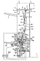
以下、本発明に係るシート処理装置としてのシート折り装置の実施形態について、図面を参照して詳細に説明する。なお、図1は、本実施形態におけるシート折り装置の構成を概略的に示す側面図である。 Hereinafter, an embodiment of a sheet folding apparatus as a sheet processing apparatus according to the present invention will be described in detail with reference to the drawings. FIG. 1 is a side view schematically showing the configuration of the sheet folding apparatus in the present embodiment.
図1に示すように、シート折り装置(シート処理装置)2は、複写機、プリンタや印刷装置等の画像形成装置1に接続された状態で使用される。この画像形成装置1は、画像形成等を施したシートをシート折り装置2側に排出するために、排紙ローラ1aと、該排紙ローラ1aに押圧されて圧接する排紙コロ1bとを備えている。
As shown in FIG. 1, a sheet folding apparatus (sheet processing apparatus) 2 is used in a state where it is connected to an
シート折り装置2は、フレーム8の内部上方に、排紙ローラ1aと排紙コロ1bとのニップ部に対向するようにシート導入部を備えており、このシート導入部に、回動軸3aを中心として回動自在に支持された入口フラッパ3を備えている。この入口フラッパ3は、入口ソレノイド(図示せず)に連繋されており、入口ソレノイドに供給される電源のON、OFFによって、整本モード又はスタックモードへの切り換え、即ち、排紙ガイド4と第1の搬送路201何れかへの経路の切り換えを実行している。
The sheet folding device 2 includes a sheet introducing portion at the upper part of the
[スタックモードの構成]
排紙ガイド4の下流側には、スタッカ排出ローラ5とスタッカ排出コロ6とが配置されている。フレーム8の上部側には、外方に突出するように、スタッカ排出ローラ5から排紙されたシートを積載するスタッカトレイ7が配設されている。排紙ガイド4には、シートを検知するセンサ84が配置されている。
[Stack mode configuration]
A stacker discharge roller 5 and a stacker discharge roller 6 are disposed on the downstream side of the sheet discharge guide 4. A stacker tray 7 for stacking sheets discharged from the stacker discharge roller 5 is disposed on the upper side of the
[整本モードの構成]
画像形成装置1側の排紙ローラ1aと排紙コロ1bとのニップ部からシートが排出されると、このシートは、図1に実線で示す位置に回動したフラッパ3に案内されて、シートガイド11,12に導入される。シートガイド11,12のシート搬送方向下流側には、回転軸13aを中心に回転する搬送ローラ13と、この搬送ローラ13に押圧されて圧接する搬送コロ14とが配設されている。
[Composition of copy mode]
When the sheet is discharged from the nip portion between the discharge roller 1a and the
そして、シートガイド11,12から続くように上シートガイド34,35が配設されている。これら上シートガイド34,35の内方には、上切換えフラッパ15と下切換えフラッパ16とが配設されている。上切換えフラッパ15及び下切換えフラッパ16には、不図示の切換えソレノイドがそれぞれに連繋されている。そして、対応する切換えソレノイドが電気的信号でON又はOFFされると、上切換えフラッパ15又は下切換えフラッパ16が、図1における一点鎖線位置と実線位置とに切り換えられるように構成されている。
上述したシートガイド11,12,34,35は、図中下方に位置するシートガイド20,21とで第1の搬送路201を構成している。この第1の搬送路201には、スポンジ状のゴム材質で形成された弾性ローラ17a,22aが配設されている。そして、これら弾性ローラ17a,22aに対向する位置には、弾性部材17d,22dがそれぞれ弾接付勢した状態で配設されている。
The
上記弾性ローラ17aの図中下方には、内部に不図示のステイプル針とモータとを備えたステイプルユニット18が配設されている。このステイプルユニット18は、回転軸18aを中心に揺動可能に構成されており、制御手段としてのCPU200によって作動制御される。このステイプルユニット18に対向するように、シートガイド21にはアンビル19が配置されている。このアンビル19は、型面19aを有しており、ステイプル18によってシート束をステイプルする際に、ステイプル針の先端を型面19aによってガイドした状態で潰す機能を有している。
A
そして、ステイプルユニット18の下流側には、上記したシートガイド20,21が配置されており、これらシートガイド20,21には幅寄せ部材24が配置されている。この幅寄せ部材24は、第1の搬送路201内に搬送されてきたシートの両サイドを押さえ、それらシートを整合するように構成されており、ステイプルユニット18等によるシート処理に先立って、CPU200からの信号で作動させられる。
The above-described sheet guides 20 and 21 are disposed on the downstream side of the
上記幅寄せ部材24よりも図中下方には、ストッパ部材であるシートストッパ23が配置されている。このシートストッパ23は、シートガイド20,21間に進入してきたシートの先端を当接させて、第1の搬送路201内でのシートの位置決めを行なう部材である。第1の搬送路201の最下部付近には、シートストッパ23の最下端位置を検知するセンサ63が配設されている。
A
シートストッパ23は、ステイプルユニット18で針打ちする際のシート位置決めと、シート折り処理の際のシート位置決めのために、シートガイド20,21に沿って図中矢印a方向に移動し得るように構成されている。シートガイド20,21の近傍には、CPU200によって作動制御されるモータ23cが配置されており、シートストッパ23には、このモータ23c側に延設されて上下方向に延びるようにラック23dが形成されている。このラック23dに、モータ23cの回転軸に固定されたピニオンギヤ23bが噛合してラックアンドピニオン(rack and pinion)が構成されている。シートストッパ23は、ラック23dの内側に上下一対のコロ23aを有しており、これらコロ23aを、フレーム8に形成されたガイド溝(図示せず)に案内されることにより、矢印a方向に円滑に移動させられる。シートガイド20,21の中央部分には、第1の搬送路201を搬送されてきたシートの先端を検知する先端検知センサ85が配置されている。
The
第1の搬送路201の途中から第2の搬送路202が分岐して設けられている。この第2の搬送路202の分岐部203側には、CPU200により作動制御され、かつ所定の圧力で互いに押圧されて圧接される上下一対の折りローラ26,27(以下、折りローラ対26,27と称する)が配置されている。折りローラ対26,27の図中左側には、第2の搬送路202を構成する排出ガイド28が配置されている。この排出ガイド28は、折りローラ対26,27を介して排出トレイ32側に排出されるシート(或いはシート束)を、排出ローラ30とコロ31とのニップ間に案内する。
A
第2の搬送路202の分岐部203に対向する位置には、突き出し部材25aを有する突き出しユニット25が配置されている。この突き出し部材25aは、図1の紙面奥−手前方向に長尺(少なくともシートの幅寸法程度の長さ)に形成されている。突き出しユニット25の近傍には、突き出し部材25aを折りローラ対26,27のニップ部に向けて進退動作させるためのモータ73aが配設されている。突き出しユニット25は、CPU200によって制御されるモータ73aの駆動により、シート折り処理の実行前には、突き出し部材25aを、シートガイド(ガイド面)21(図4参照)に形成された開口部37bから外側に退避させる。そして、シート折り処理の実行時には、折りローラ対26,27のニップ部直前まで突出させる。
A protruding
折りローラ対26,27と排出ローラ30,コロ31との間には、シート(シート束)の前端及び後端を検知する排出センサ29が配設されている。フレーム8の下部側には、排出ローラ30,コロ31のニップ部を通って排出されたシート(シート束)を積載する排出トレイ32が配設されている。
Disposed between the pair of
第2の搬送路202の分岐部203近傍には、この分岐部203を開閉するシャッター手段としての折りローラカバー33が配置されている。折りローラカバー33は、折りローラ対26,27と開口部37a(図4参照)との間を覆って第1の搬送路201から仕切ることで、シートガイド20を上下方向に真直ぐにつなぐ。これにより、第1の搬送路201を搬送されてくるシートが折りローラ対26,27に引っ掛かるような不都合を防ぐように機能する。一方、シート束の折り動作が実行される際には、折りローラカバー33の駆動用モータ61がCPU200の制御で駆動されることにより、折りローラカバー33が分岐部203(つまり、開口部37a)を開口する。
A
[折りローラカバー駆動機構]
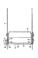
ここで、折りローラカバー33を駆動する駆動機構について、図1及び図2を参照して説明する。なお、図2は、折りローラ対及びその近傍部位を示す平面図である。
[Folding roller cover drive mechanism]
Here, a driving mechanism for driving the
折りローラカバー33は、上述したように、シートガイド34,35間から第1の搬送路201に進入してきたシートの先端が折りローラ26,27に引っ掛かるような不都合を防ぐように機能する。両図に示すように、折りローラカバー33は、その両端に複数のコロ33aが回転自在に取付けられており、それらコロ33aがフレーム8に形成された溝部(図示せず)に案内されることにより第1の搬送路201に沿ってスライド移動する。
As described above, the folding roller cover 33 functions to prevent a problem that the leading edge of the sheet that has entered the
折りローラカバー33の両端にはラック91が設けられている(図2には不図示)。また、折りローラカバー33には、その幅方向(図2の左右方向)に沿って軸33cが設けられており、この軸33cの両端にはピニオンギヤ33bがそれぞれ固着され、これらピニオンギヤ33bは軸33cと共に一体回転するようになっている。上記軸33cの両端のラック91は、これら2つのピニオンギヤ33bにそれぞれ噛合している。
また、軸33cの一端(図2の左側)には、フレーム8の外側において折りローラカバーギヤ33dが固着されている。折りローラカバーギヤ33dの近傍には、ステッピングモータからなる折りローラカバーモータ61が配設されており、このモータ61の回転軸に固着されたピニオンギヤ62には、折りローラカバーギヤ33dが噛合している。また、折りローラカバー33の一部にはフラグが形成されており、折りローラカバー33がホームポジションまで到達したときに、不図示の折りローラカバーホームセンサによって上記フラグを検知するようになっている。
A folding
従って、折りローラカバーモータ61が回転駆動すると、その駆動力は、ピニオンギヤ62、折りローラカバーギヤ33d、及び軸33cを介してピニオンギヤ33bに伝達される。これにより、左右のラック91が移動させられ、折りローラカバー33が図1の上下方向に移動することとなる。
Therefore, when the folding roller cover motor 61 is rotationally driven, the driving force is transmitted to the
[動作概要]
次に、図1乃至図3を用いて、本実施の形態に係るシート折り装置2の動作の概要について説明する。なお、図3は、シート束に対する折り処理の動作を説明する概略側面図である。(a)はシート搬送路内における折り処理前のシート束を示し、(b)はシート搬送路内にシートが更に集められた状態を示し、(c)はシート束に第1の折り目を形成する工程を示している。
[Operation overview]
Next, an outline of the operation of the sheet folding apparatus 2 according to the present embodiment will be described with reference to FIGS. 1 to 3. FIG. 3 is a schematic side view for explaining the operation of the folding process for the sheet bundle. (A) shows a sheet bundle before folding in the sheet conveyance path, (b) shows a state in which sheets are further collected in the sheet conveyance path, and (c) shows a first fold formed in the sheet bundle. The process to perform is shown.
まず、画像形成装置1から排出されたシートSは、搬送ローラ13及び弾性ローラ17a,22a等により搬送され、その先端がシートストッパ23に当接することで(図1参照)、シート束の位置決めがなされる。そして、シート束の搬送方向の長さ(幅)の中央位置(半分の位置)がステイプラユニット18により針綴じできるように積載される。この際、折りローラカバー33は、図3(a)に示すように折りローラ対26,27を覆う位置に停止されており、従って、第1の搬送路201を搬送されているシートSがカール等により曲っていても、そのシートが折りローラに引っ掛かることはない。
First, the sheet S discharged from the
次いで、図3(b)に示すように所定枚数のシートSが第1の搬送路201に積載されると、その後、ステイプラユニット18によってシート束の針綴じが行なわれる。そして、針綴じされたシート束の折り畳み動作のためにシートストッパ23が下方に移動する際に、折りローラカバー33も下方に移動して、この折りローラカバー33が突き出しユニット25の折り畳み動作を妨げない位置で停止する。
Next, as shown in FIG. 3B, when a predetermined number of sheets S are stacked on the
引き続き、シート束の中央位置が折りローラ対26,27のニップ部に重なる位置でシートストッパ23が停止される。その後、突き出しユニット25が作動させられて、突き出しユニット25が、第1方向A1,A2に予め回転している折りローラ対26,27のニップ部にシート束を押して送り込む。これにより、図3(c)に示すように、折りローラ対26,27がシート束を引き込み、その折り畳み動作を行う。
Subsequently, the
このようにして折り畳まれたシート束は、排出ローラ30及び排出コロ31を介して排出トレイ32上に排出され、これにより、二つ折り処理に係る一連のシート折り動作が終了する。
The sheet bundle folded in this way is discharged onto the
次に、本発明に係るシート折り装置2により実行される三つ折り処理について、図4を参照して説明する。ここでは、等間隔の三つ折り処理を例に挙げる。また、シート束に代えて1枚のシートSに関して説明するが、以下の処理は、複数枚のシートを束ねたシート束に対しても同様に実行され得ることは勿論である。 Next, the tri-folding process executed by the sheet folding apparatus 2 according to the present invention will be described with reference to FIG. Here, an example of an equally spaced tri-fold process will be described. Although one sheet S will be described instead of the sheet bundle, the following processing can of course be executed similarly on a sheet bundle obtained by bundling a plurality of sheets.
なお、図4は、シートに対する三つ折り処理の動作を説明する概略側面図である。(a)はシート搬送路内における折り処理前のシートを示し、(b)はシートに第1の折り目を形成する工程を示し、(c)は第1の折り目を形成したシートをシート搬送路内に戻した状態を示している。(d)は第2の折り目形成前のシートを示し、(e)はシートに第2の折り目を形成する工程を示し、(f)は三つ折り処理後のシートを示している。 FIG. 4 is a schematic side view for explaining the operation of the tri-fold process for the sheet. (A) shows the sheet before the folding process in the sheet conveying path, (b) shows the step of forming the first fold on the sheet, and (c) shows the sheet on which the first fold is formed on the sheet conveying path. The state returned to inside is shown. (D) shows the sheet before forming the second crease, (e) shows the step of forming the second crease on the sheet, and (f) shows the sheet after the trifold process.
シート折り装置2は、第1の搬送路201におけるシートガイド20,21の対向する部位に開口部37a,37bを有すると共に、上述した折りローラ対26,27と、シートストッパ23と、突き出しユニット25の突き出し部材25aとを有している。折りローラ対26,27は、開口部37aを臨む位置に配置され、第1の搬送路201からシートSを引き込む第1方向A1,A2と、第1の搬送路201にシートSを戻す第2方向B1,B2とに回転自在に構成される。図4(c)に示すように、折りローラ26の斜め上部には軸38aが設けられており、軸38aには、この軸38aを中心として回動するフラッパ38が固着されている。
The sheet folding apparatus 2 has
シートストッパ23は、第1の搬送路201内にて折りローラ対26,27のニップ部39から、予め定められた距離だけ離間する第1位置(図4(a))と、第1位置より折りローラ対26,27側に近接する第2位置(図4(d))とに切り換えられる。このように移動し停止されて第1位置又は第2位置に切り換えられたシートストッパ23は、第1の搬送路201内を搬送されてくるシートSの先端を当接させる。そして、突き出し部材25aは、開口部37bを臨む位置に配置されており、第1の搬送路201内のシートSを、予め設定されたタイミングでニップ部39に向けて突き出すように作動する。
The
第1位置は、シートストッパ23に先端が当接した折り処理前のシートSの全長Lの当該先端から2/3の長さに対応する位置である。また第2位置は、シートストッパ23に先端が当接した折り処理前のシートSの全長の当該先端から1/3の長さに対応する位置である。
The first position is a position corresponding to a length of 2/3 from the leading end of the total length L of the sheet S before the folding process in which the leading end is in contact with the
そして、使用者が、画像形成装置1に備えている操作パネル(図示せず)から、シートSのサイズと、等間隔の三つ折り処理とを選択して入力すると、それらの情報がCPU200に伝達され、このCPU200の制御によって以下の作動が実行される。
When the user selects and inputs the size of the sheet S and the tri-fold processing at equal intervals from an operation panel (not shown) provided in the
即ち、図4(a)に示すように、CPU200の制御によるモータ23cの駆動で、シートストッパ23を、シート全長Lの先端から2/3の長さに対応する第1位置に切り換える。そして、この状態で折りローラ対26,27を第1方向A1,A2に回転させるように制御する。
That is, as shown in FIG. 4A, the driving of the motor 23c under the control of the
次いで、CPU200が、図4(b)に示すように、折りローラ対26,27を第1方向A1,A2に回転させた状態で、モータ73a(図1参照)を回転駆動し、突き出し部材25aを図の左方に突出作動させるように制御する。これにより、シートストッパ23に先端を当接させたシートSは、シート全長Lの後端から1/3の部位を折り込まれ、第1の折り目f1が形成される。この際、シートSの後端S1が折りローラ対26,27のニップ部39のニップ点から手前に(即ち、分岐部203内に)2[mm]残っている時点で、折りローラ対26,27の回転が停止される。これにより、のちのローラ逆転時にも、シートSの搬送が適正に行われることになる。
Next, as shown in FIG. 4B, the
CPU200は、図4(c)に示すように、軸38aを中心にフラッパ38を時計回り方向に回転させると共に、折りローラ対26,27を第2方向B1,B2に回転させ、シートSをフラッパ(摺接部材)38に摺接させつつ第1の搬送路201内に戻すように制御する。つまり、折りローラ対26,27の逆転前には、第1の搬送路201の外方に回転して待機していたフラッパ38が、CPU200の制御に基づく駆動機構(図示せず)の駆動で、破線で示す初期位置から実線で示す作動位置に回転する。このため、戻されるシートSは、第1の搬送路201内に適正に導かれる。そして、フラッパ38は、シートSが安定した時点で、再び初期位置(図4(c)の破線位置)に復帰するように回転する。
As shown in FIG. 4C, the
引き続き、CPU200は、図4(d)に示すように、シートストッパ23を、シート全長Lの先端から1/3の長さに対応する第2位置に切り換えるように、モータ23cを作動させて停止する。更にこの状態で、折りローラ対26,27を第1方向A1,A2に回転させると共に、突き出し部材25aを突出作動させる。これにより、図4(e)に示すように、シートストッパ23に先端を当接させたシートSは、シート全長Lの先端から1/3の部位を折り込まれ、第2の折り目f2が形成される。
Subsequently, as shown in FIG. 4D, the
その後も、CPU200は、折りローラ対26,27を第1方向A1,A2に続けて回転させるように制御する。これにより、第1及び第2の折り目f1,f2を形成されて三つ折り処理を施されたシートS(図4(f)参照)が、排出ローラ30とコロ31を介して排出トレイ32上に排出される。
After that, the
以上のように本実施の形態では、2つのローラからなる折りローラ対26,27と、異なる位置でシートSの先端を当接させるシートストッパ23とを第1の搬送路201に対応して配置している。そして、それらに予め設定された作動を行わせるだけで、シート(或いはシート束)に対する適正な三つ折り処理を施すことができるように構成される。
As described above, in the present embodiment, the pair of
このように、従来は三つ折り処理に、比較的高価な折りローラが3本必要であったのに対し、本実施形態によれば、2本のみの折りローラ対26,27で同様の三つ折り処理を実行することができる。これにより、構造が大幅に簡略化されて、専用装置に限らず汎用装置に適用することが可能になるので、比較的高価な折りローラを始めとする種々の部品点数を削減し、製造コストを低減することが可能となる。 As described above, the conventional three-folding process requires three relatively expensive folding rollers, but according to the present embodiment, only two folding roller pairs 26 and 27 are used to perform the same three-folding. Processing can be executed. As a result, the structure is greatly simplified and can be applied not only to a dedicated device but also to a general-purpose device. Therefore, the number of various parts including a relatively expensive folding roller can be reduced, and the manufacturing cost can be reduced. It becomes possible to reduce.
2 シート処理装置(シート折り装置)
21a,21b ガイド面
23 ストッパ部材(シートストッパ)
25 突き出しユニット
25a 突き出し部材
26,27 折りローラ対
37a,37b 開口部
38 フラッパ
39 ニップ部
200 CPU
201 シート搬送路(第1の搬送路)
A1,A2 第1方向
B1,B2 第2方向
f1 第1の折り目
f2 第2の折り目
S シート
2 Sheet processing device (sheet folding device)
21a,
25
201 Sheet transport path (first transport path)
A 1 , A 2 first direction B 1 , B 2 second direction f 1 first crease f 2 second crease S sheet
Claims (3)
前記シート搬送路からシートを引き込みシートに折りを施す第1方向と該シート搬送路にシートを戻す第2方向とに回転自在な折りローラ対と、
前記シート搬送路にて前記折りローラ対のニップ部から、予め定められた距離だけ離間した第1位置と、該第1位置より前記折りローラ対側に近接する第2位置とに移動可能であり、前記シート搬送路に搬送されるシートの先端を当接させ得るストッパ部材と、
前記シート搬送路内のシートを前記ニップ部に向けて突き出す突き出し部材と、を備え、
前記ストッパ部材を前記第1位置にした状態で、前記折りローラ対を前記第1方向に回転させると共に前記突き出し部材を前記ニップ部に向けて突き出して、前記ストッパ部材に先端が当接したシートに第1の折り目を形成した後、前記折りローラ対を前記第2方向に回転させて該シートを前記シート搬送路に戻し、更に、前記ストッパ部材を前記第2位置に切り換えた状態で、前記折りローラ対を前記第1方向に回転させると共に前記突き出し部材を前記ニップ部に向けて突き出して該シートに第2の折り目を形成する、
ことを特徴とするシート処理装置。 A sheet conveyance path ;
A rotatable folding roller pair and a second direction to return the sheet in a first direction and the sheet conveyance path for applying the fold to Write-sheet pull the sheet from the sheet conveying path,
From the nip portion of the pair of folding rollers hand to the sheet conveying path is movable between a first position spaced apart a predetermined distance, and a second position adjacent to said pair of folding rollers side than the first position a stopper member which can be abutted against the leading edge of the sheet to be conveyed to the sheet conveying path,
And a member out can be butt protruding toward the front Symbol nip the sheet before Symbol sheet conveying path,
With the stopper member in the first position , the folding roller pair is rotated in the first direction, and the protruding member is protruded toward the nip portion, so that the leading end of the sheet contacts the stopper member. After forming the first fold, the folding roller pair is rotated in the second direction to return the sheet to the sheet conveying path, and the folding member is switched to the second position. that forms form a second fold in the sheet of the ejection member to rotate the roller pair in the first direction protrudes toward the nip portion,
A sheet processing apparatus.
前記第2位置は、前記ストッパ部材に先端が当接した折り処理前のシートの全長の該先端から1/3の長さに対応する位置である、
請求項1記載のシート処理装置。 The first position is a position corresponding to a length of 2/3 from the front end of the full length of the sheet before folding with the front end in contact with the stopper member;
The second position is a position corresponding to a length of 1/3 from the front end of the full length of the sheet before the folding process in which the front end is in contact with the stopper member.
The sheet processing apparatus according to claim 1.
請求項1又は2記載のシート処理装置。 The sheet processing apparatus according to claim 1 or 2.
Priority Applications (1)
| Application Number | Priority Date | Filing Date | Title |
|---|---|---|---|
| JP2006200741A JP4722786B2 (en) | 2006-07-24 | 2006-07-24 | Sheet processing device |
Applications Claiming Priority (1)
| Application Number | Priority Date | Filing Date | Title |
|---|---|---|---|
| JP2006200741A JP4722786B2 (en) | 2006-07-24 | 2006-07-24 | Sheet processing device |
Publications (3)
| Publication Number | Publication Date |
|---|---|
| JP2008024474A JP2008024474A (en) | 2008-02-07 |
| JP2008024474A5 JP2008024474A5 (en) | 2009-09-10 |
| JP4722786B2 true JP4722786B2 (en) | 2011-07-13 |
Family
ID=39115514
Family Applications (1)
| Application Number | Title | Priority Date | Filing Date |
|---|---|---|---|
| JP2006200741A Active JP4722786B2 (en) | 2006-07-24 | 2006-07-24 | Sheet processing device |
Country Status (1)
| Country | Link |
|---|---|
| JP (1) | JP4722786B2 (en) |
Family Cites Families (3)
| Publication number | Priority date | Publication date | Assignee | Title |
|---|---|---|---|---|
| JP2004018161A (en) * | 2002-06-14 | 2004-01-22 | Konica Minolta Holdings Inc | Paper post-processing device |
| JP4209249B2 (en) * | 2003-05-08 | 2009-01-14 | 株式会社リコー | Paper stacking device, paper processing device, and image forming system |
| JP4149864B2 (en) * | 2003-06-30 | 2008-09-17 | トッパン・フォームズ株式会社 | Single piece paper processing equipment |
-
2006
- 2006-07-24 JP JP2006200741A patent/JP4722786B2/en active Active
Also Published As
| Publication number | Publication date |
|---|---|
| JP2008024474A (en) | 2008-02-07 |
Similar Documents
| Publication | Publication Date | Title |
|---|---|---|
| JP4088206B2 (en) | Paper folding device, paper processing device, and image forming system | |
| JP2008013341A (en) | Sheet alignment device, sheet processing device, and image formation device | |
| JP2009051637A (en) | Home position detection method, paper sheet processing device and image forming device | |
| JP2009051594A (en) | Paper sheet conveying device, paper sheet processing device and image forming device | |
| JP5310270B2 (en) | Paper folding apparatus and image forming system | |
| JP5151711B2 (en) | Sheet processing apparatus and image forming apparatus | |
| JP5987452B2 (en) | Post-processing apparatus and image forming apparatus | |
| JP5129036B2 (en) | Sheet folding apparatus, sheet conveying apparatus, sheet post-processing apparatus, and image forming apparatus | |
| JP4774345B2 (en) | Sheet aligning apparatus and image forming apparatus | |
| JP4722786B2 (en) | Sheet processing device | |
| JP4506590B2 (en) | Paper post-processing apparatus, image forming apparatus having the same, and paper post-processing method | |
| US8262073B2 (en) | Sheet processing apparatus | |
| JP4377830B2 (en) | Paper folding device | |
| JP5867183B2 (en) | Paper processing apparatus, image forming system having the same, and paper folding method | |
| JP2022071242A (en) | Sheet folding apparatus | |
| JP5446628B2 (en) | Sheet processing apparatus and image forming apparatus | |
| JP5446831B2 (en) | Paper folding device | |
| JP7419581B2 (en) | Sheet folding device, sheet processing device, and image forming device | |
| JP2022071243A (en) | Sheet binding and folding processing apparatus | |
| JP5565257B2 (en) | Paper folding device | |
| JP2022071339A (en) | Sheet folding device | |
| JP5595009B2 (en) | Sheet folding apparatus and image forming system provided with the same | |
| JP4467486B2 (en) | Sheet processing apparatus and image forming apparatus | |
| JP3623574B2 (en) | Sheet folding device | |
| JP5500434B2 (en) | Paper folding device |
Legal Events
| Date | Code | Title | Description |
|---|---|---|---|
| A521 | Request for written amendment filed |
Free format text: JAPANESE INTERMEDIATE CODE: A523 Effective date: 20090723 |
|
| A621 | Written request for application examination |
Free format text: JAPANESE INTERMEDIATE CODE: A621 Effective date: 20090723 |
|
| A977 | Report on retrieval |
Free format text: JAPANESE INTERMEDIATE CODE: A971007 Effective date: 20110112 |
|
| TRDD | Decision of grant or rejection written | ||
| A01 | Written decision to grant a patent or to grant a registration (utility model) |
Free format text: JAPANESE INTERMEDIATE CODE: A01 Effective date: 20110405 |
|
| A01 | Written decision to grant a patent or to grant a registration (utility model) |
Free format text: JAPANESE INTERMEDIATE CODE: A01 |
|
| A61 | First payment of annual fees (during grant procedure) |
Free format text: JAPANESE INTERMEDIATE CODE: A61 Effective date: 20110406 |
|
| FPAY | Renewal fee payment (event date is renewal date of database) |
Free format text: PAYMENT UNTIL: 20140415 Year of fee payment: 3 |
|
| R150 | Certificate of patent or registration of utility model |
Ref document number: 4722786 Country of ref document: JP Free format text: JAPANESE INTERMEDIATE CODE: R150 Free format text: JAPANESE INTERMEDIATE CODE: R150 |
|
| R250 | Receipt of annual fees |
Free format text: JAPANESE INTERMEDIATE CODE: R250 |
|
| S531 | Written request for registration of change of domicile |
Free format text: JAPANESE INTERMEDIATE CODE: R313532 |
|
| R350 | Written notification of registration of transfer |
Free format text: JAPANESE INTERMEDIATE CODE: R350 |
|
| R250 | Receipt of annual fees |
Free format text: JAPANESE INTERMEDIATE CODE: R250 |
|
| R250 | Receipt of annual fees |
Free format text: JAPANESE INTERMEDIATE CODE: R250 |
|
| R250 | Receipt of annual fees |
Free format text: JAPANESE INTERMEDIATE CODE: R250 |
|
| S533 | Written request for registration of change of name |
Free format text: JAPANESE INTERMEDIATE CODE: R313533 |
|
| R350 | Written notification of registration of transfer |
Free format text: JAPANESE INTERMEDIATE CODE: R350 |
|
| R250 | Receipt of annual fees |
Free format text: JAPANESE INTERMEDIATE CODE: R250 |
|
| R250 | Receipt of annual fees |
Free format text: JAPANESE INTERMEDIATE CODE: R250 |
|
| R250 | Receipt of annual fees |
Free format text: JAPANESE INTERMEDIATE CODE: R250 |
|
| R250 | Receipt of annual fees |
Free format text: JAPANESE INTERMEDIATE CODE: R250 |
|
| R250 | Receipt of annual fees |
Free format text: JAPANESE INTERMEDIATE CODE: R250 |
|
| R250 | Receipt of annual fees |
Free format text: JAPANESE INTERMEDIATE CODE: R250 |
|
| R250 | Receipt of annual fees |
Free format text: JAPANESE INTERMEDIATE CODE: R250 |