JP4722033B2 - System and method for accessing the coronary sinus to facilitate insertion of a pacing lead - Google Patents
System and method for accessing the coronary sinus to facilitate insertion of a pacing lead Download PDFInfo
- Publication number
- JP4722033B2 JP4722033B2 JP2006503019A JP2006503019A JP4722033B2 JP 4722033 B2 JP4722033 B2 JP 4722033B2 JP 2006503019 A JP2006503019 A JP 2006503019A JP 2006503019 A JP2006503019 A JP 2006503019A JP 4722033 B2 JP4722033 B2 JP 4722033B2
- Authority
- JP
- Japan
- Prior art keywords
- outer cylinder
- stylet
- guiding catheter
- catheter system
- lumen
- Prior art date
- Legal status (The legal status is an assumption and is not a legal conclusion. Google has not performed a legal analysis and makes no representation as to the accuracy of the status listed.)
- Expired - Fee Related
Links
- 210000003748 coronary sinus Anatomy 0.000 title description 19
- 238000000034 method Methods 0.000 title description 10
- 238000003780 insertion Methods 0.000 title 1
- 230000037431 insertion Effects 0.000 title 1
- 238000004891 communication Methods 0.000 claims abstract description 7
- 239000012530 fluid Substances 0.000 claims abstract description 7
- 230000007246 mechanism Effects 0.000 claims description 9
- 230000008719 thickening Effects 0.000 claims 1
- 210000004204 blood vessel Anatomy 0.000 description 7
- 239000000463 material Substances 0.000 description 7
- 230000002526 effect on cardiovascular system Effects 0.000 description 6
- 210000005245 right atrium Anatomy 0.000 description 6
- 239000002131 composite material Substances 0.000 description 5
- 210000003462 vein Anatomy 0.000 description 5
- 230000002787 reinforcement Effects 0.000 description 4
- 238000012986 modification Methods 0.000 description 3
- 230000004048 modification Effects 0.000 description 3
- 210000002620 vena cava superior Anatomy 0.000 description 3
- 206010007559 Cardiac failure congestive Diseases 0.000 description 2
- 206010019280 Heart failures Diseases 0.000 description 2
- 230000036760 body temperature Effects 0.000 description 2
- 238000002513 implantation Methods 0.000 description 2
- -1 polyethylene Polymers 0.000 description 2
- 239000004810 polytetrafluoroethylene Substances 0.000 description 2
- 229920001343 polytetrafluoroethylene Polymers 0.000 description 2
- 238000000926 separation method Methods 0.000 description 2
- 210000005166 vasculature Anatomy 0.000 description 2
- VGGSQFUCUMXWEO-UHFFFAOYSA-N Ethene Chemical compound C=C VGGSQFUCUMXWEO-UHFFFAOYSA-N 0.000 description 1
- 229920002614 Polyether block amide Polymers 0.000 description 1
- 239000004698 Polyethylene Substances 0.000 description 1
- 230000009471 action Effects 0.000 description 1
- 238000007792 addition Methods 0.000 description 1
- 210000003484 anatomy Anatomy 0.000 description 1
- 238000013459 approach Methods 0.000 description 1
- 230000001746 atrial effect Effects 0.000 description 1
- 230000009286 beneficial effect Effects 0.000 description 1
- 230000017531 blood circulation Effects 0.000 description 1
- 230000000747 cardiac effect Effects 0.000 description 1
- 230000007812 deficiency Effects 0.000 description 1
- 230000000694 effects Effects 0.000 description 1
- 238000001125 extrusion Methods 0.000 description 1
- 210000002837 heart atrium Anatomy 0.000 description 1
- 208000019622 heart disease Diseases 0.000 description 1
- 230000002439 hemostatic effect Effects 0.000 description 1
- 229920001903 high density polyethylene Polymers 0.000 description 1
- 239000004700 high-density polyethylene Substances 0.000 description 1
- 239000007943 implant Substances 0.000 description 1
- 238000002347 injection Methods 0.000 description 1
- 239000007924 injection Substances 0.000 description 1
- 210000005240 left ventricle Anatomy 0.000 description 1
- 229920001684 low density polyethylene Polymers 0.000 description 1
- 239000004702 low-density polyethylene Substances 0.000 description 1
- 238000004519 manufacturing process Methods 0.000 description 1
- 238000012806 monitoring device Methods 0.000 description 1
- HLXZNVUGXRDIFK-UHFFFAOYSA-N nickel titanium Chemical compound [Ti].[Ti].[Ti].[Ti].[Ti].[Ti].[Ti].[Ti].[Ti].[Ti].[Ti].[Ni].[Ni].[Ni].[Ni].[Ni].[Ni].[Ni].[Ni].[Ni].[Ni].[Ni].[Ni].[Ni].[Ni] HLXZNVUGXRDIFK-UHFFFAOYSA-N 0.000 description 1
- 229910001000 nickel titanium Inorganic materials 0.000 description 1
- 239000004033 plastic Substances 0.000 description 1
- 229920003023 plastic Polymers 0.000 description 1
- 229920000573 polyethylene Polymers 0.000 description 1
- 230000000750 progressive effect Effects 0.000 description 1
- 230000003014 reinforcing effect Effects 0.000 description 1
- 239000007779 soft material Substances 0.000 description 1
- 230000000087 stabilizing effect Effects 0.000 description 1
- 229910001220 stainless steel Inorganic materials 0.000 description 1
- 239000010935 stainless steel Substances 0.000 description 1
- 210000001321 subclavian vein Anatomy 0.000 description 1
- 208000024891 symptom Diseases 0.000 description 1
- 210000002435 tendon Anatomy 0.000 description 1
- 230000007704 transition Effects 0.000 description 1
Images


Classifications
-
- A—HUMAN NECESSITIES
- A61—MEDICAL OR VETERINARY SCIENCE; HYGIENE
- A61N—ELECTROTHERAPY; MAGNETOTHERAPY; RADIATION THERAPY; ULTRASOUND THERAPY
- A61N1/00—Electrotherapy; Circuits therefor
- A61N1/02—Details
- A61N1/04—Electrodes
- A61N1/05—Electrodes for implantation or insertion into the body, e.g. heart electrode
- A61N1/056—Transvascular endocardial electrode systems
-
- A—HUMAN NECESSITIES
- A61—MEDICAL OR VETERINARY SCIENCE; HYGIENE
- A61M—DEVICES FOR INTRODUCING MEDIA INTO, OR ONTO, THE BODY; DEVICES FOR TRANSDUCING BODY MEDIA OR FOR TAKING MEDIA FROM THE BODY; DEVICES FOR PRODUCING OR ENDING SLEEP OR STUPOR
- A61M25/00—Catheters; Hollow probes
- A61M25/0043—Catheters; Hollow probes characterised by structural features
- A61M2025/0063—Catheters; Hollow probes characterised by structural features having means, e.g. stylets, mandrils, rods or wires to reinforce or adjust temporarily the stiffness, column strength or pushability of catheters which are already inserted into the human body
-
- A—HUMAN NECESSITIES
- A61—MEDICAL OR VETERINARY SCIENCE; HYGIENE
- A61M—DEVICES FOR INTRODUCING MEDIA INTO, OR ONTO, THE BODY; DEVICES FOR TRANSDUCING BODY MEDIA OR FOR TAKING MEDIA FROM THE BODY; DEVICES FOR PRODUCING OR ENDING SLEEP OR STUPOR
- A61M25/00—Catheters; Hollow probes
- A61M25/01—Introducing, guiding, advancing, emplacing or holding catheters
- A61M25/09—Guide wires
- A61M2025/09133—Guide wires having specific material compositions or coatings; Materials with specific mechanical behaviours, e.g. stiffness, strength to transmit torque
- A61M2025/09141—Guide wires having specific material compositions or coatings; Materials with specific mechanical behaviours, e.g. stiffness, strength to transmit torque made of shape memory alloys which take a particular shape at a certain temperature
-
- A—HUMAN NECESSITIES
- A61—MEDICAL OR VETERINARY SCIENCE; HYGIENE
- A61M—DEVICES FOR INTRODUCING MEDIA INTO, OR ONTO, THE BODY; DEVICES FOR TRANSDUCING BODY MEDIA OR FOR TAKING MEDIA FROM THE BODY; DEVICES FOR PRODUCING OR ENDING SLEEP OR STUPOR
- A61M25/00—Catheters; Hollow probes
- A61M25/01—Introducing, guiding, advancing, emplacing or holding catheters
- A61M25/09—Guide wires
- A61M25/09016—Guide wires with mandrils
- A61M25/09025—Guide wires with mandrils with sliding mandrils
-
- A—HUMAN NECESSITIES
- A61—MEDICAL OR VETERINARY SCIENCE; HYGIENE
- A61M—DEVICES FOR INTRODUCING MEDIA INTO, OR ONTO, THE BODY; DEVICES FOR TRANSDUCING BODY MEDIA OR FOR TAKING MEDIA FROM THE BODY; DEVICES FOR PRODUCING OR ENDING SLEEP OR STUPOR
- A61M25/00—Catheters; Hollow probes
- A61M25/10—Balloon catheters
- A61M25/1011—Multiple balloon catheters
-
- A—HUMAN NECESSITIES
- A61—MEDICAL OR VETERINARY SCIENCE; HYGIENE
- A61N—ELECTROTHERAPY; MAGNETOTHERAPY; RADIATION THERAPY; ULTRASOUND THERAPY
- A61N1/00—Electrotherapy; Circuits therefor
- A61N1/02—Details
- A61N1/04—Electrodes
- A61N1/05—Electrodes for implantation or insertion into the body, e.g. heart electrode
- A61N1/056—Transvascular endocardial electrode systems
- A61N2001/0585—Coronary sinus electrodes
Abstract
Description
本発明は、一般にガイディングカテーテルシステムに、及びより詳細には右心房から冠状静脈洞にアクセスするためのガイディングカテーテルに関する。 The present invention relates generally to guiding catheter systems, and more particularly to guiding catheters for accessing the coronary sinus from the right atrium.
ガイディングカテーテルは、医師が静脈造影及び心臓ペーシングデバイスの植え込みを含む様々な医学的手技を実施するために、患者の心臓内の血管の位置を特定してカニュレーションすることを可能にする器具である。心血管にカニュレーションするためには、径の小さな可撓性を有するガイドを回旋状血管構造を介して心室内へ、そして次に標的としての心血管へ誘導する必要がある。標的心臓血管に到達すると、カテーテルはその血管内に有効装填物を挿入するための導管として機能する。 A guiding catheter is an instrument that allows a physician to locate and cannulate blood vessels within a patient's heart to perform a variety of medical procedures, including venography and implantation of a cardiac pacing device. is there. In order to cannulate into the cardiovascular, it is necessary to guide a flexible guide of small diameter through the convoluted vasculature into the ventricle and then into the target cardiovascular. Upon reaching the target cardiovascular, the catheter functions as a conduit for inserting an effective load into the blood vessel.
ガイディングカテーテル手技の主要目標は、最小の時間量で目標とする血管を見つけてカニュレーションすることである。例えば、冠状静脈洞を見つけてカニュレーションすることは、健常な患者においてさえ時間のかかる試行錯誤的な手技となることがある。進行性心疾患の症状を示す患者は心臓構造の閉塞又は変形を有する可能性があるので、右心房から冠状静脈洞の開口部(静脈口)の位置を決定する作業はより複雑になる。 The main goal of the guiding catheter procedure is to find and cannulate the target vessel with the minimum amount of time. For example, finding and cannulating the coronary sinus can be a time consuming trial and error procedure even in healthy patients. The task of determining the location of the coronary sinus opening (venous port) from the right atrium is more complicated because patients with symptoms of progressive heart disease may have obstruction or deformation of the heart structure.
標的血管の位置を決定するために、従来は予備成形されたガイディングカテーテルが使用されていた。形状が固定されたカテーテルは、経路が顕著な回旋状でなく、且つ経路が患者間で大きく相違していない多くの場合に好適である。だが構造異常又は重大な変形が存在する状況では、形状の固定されたカテーテルを使用するには、医師は潜在的変形に対応するために多数のサイズ及び形状のカテーテルを準備しておく必要がある。さらに、形状の固定されたカテーテルは、操縦が困難であるために植え込み手技中に様々な形状のカテーテルと交換する必要が生じることがある。 Conventionally, a pre-formed guiding catheter has been used to determine the location of the target vessel. A catheter with a fixed shape is suitable in many cases where the path is not significantly convoluted and the path is not significantly different between patients. But in situations where there are structural anomalies or significant deformations, the use of fixed shape catheters requires physicians to have multiple sizes and shapes of catheters to accommodate potential deformations. . In addition, fixed shape catheters may be difficult to navigate and may need to be replaced with various shaped catheters during the implantation procedure.
場合によっては、カテーテルの遠位端を動的に成形する能力があることが望ましい。カニュレーション中にカテーテルの遠位端を方向付けるのに役立つように操縦用テンドン又はワイヤーを利用するガイディングカテーテルもある。この方法が有効な場合もあるが、ワイヤー及び関連するハードウエアはカテーテルのガイドルーメン内の貴重なスペースを占有する。さらに、ガイドカテーテルが通過する相当長い(また、回旋状である可能性がある)通路は、操縦用ワイヤーの使用において引張摩擦や機械的反跳を含む面倒を引き起こすことがある。 In some cases, it is desirable to be able to dynamically shape the distal end of the catheter. Some guiding catheters utilize a steering tendon or wire to help direct the distal end of the catheter during cannulation. While this method may be effective, the wires and associated hardware occupy valuable space within the catheter guide lumen. In addition, the fairly long (and possibly convoluted) path through which the guide catheter passes can cause troublesome use, including tensile friction and mechanical recoil, in the use of steering wires.
そこで、プルワイヤーを利用しない操縦可能な遠位端を備えるガイドカテーテルに対する必要がある。本発明はこれらやその他の必要を満たし、さらに先行技術の器具類及び技術の他の欠陥に対処する。 Thus, there is a need for a guide catheter with a steerable distal end that does not utilize a pull wire. The present invention fulfills these and other needs, and further addresses other deficiencies in the prior art instruments and techniques.
上述した先行技術における限界を克服し、そして本明細書を読んで理解すると明白になるその他の限界を克服するために、本発明は医学的手技のために静脈構造へのアクセスを提供できる操縦可能なガイディングカテーテルを開示する。 In order to overcome the limitations in the prior art described above and to overcome other limitations that will become apparent upon reading and understanding this specification, the present invention is steerable that can provide access to venous structures for medical procedures. A guiding catheter is disclosed.
本発明の1つの実施形態によると、患者の心臓にアクセスするためのガイディングカテーテルシステムは、1つの開口ガイドルーメンを有する外筒と、該外筒の外面に沿って設けられた少なくとも1つのインフレーションルーメンと、及び該外筒の遠位部分に固定可能に取り付けられた遠位バルーンの少なくとも1つのセグメントと、を含んでいる。外筒は、該外筒の長手方向長さに沿って設けられたピールアウェイ機構を含むように構成することができる。該遠位バルーンは、インフレーションルーメンと流体連絡している。該インフレーションルーメン内には1つ以上の第2バルーンを、該第2バルーンが遠位バルーンセグメントの近位に据えられるように組み込むことができる。 According to one embodiment of the present invention, a guiding catheter system for accessing a patient's heart includes an outer tube having one open guide lumen and at least one inflation provided along an outer surface of the outer tube. And a lumen and at least one segment of a distal balloon fixedly attached to a distal portion of the barrel. The outer cylinder can be configured to include a peel-away mechanism provided along the longitudinal length of the outer cylinder. The distal balloon is in fluid communication with the inflation lumen. One or more second balloons may be incorporated within the inflation lumen such that the second balloon is positioned proximal to the distal balloon segment.
該外筒のガイドルーメン内にはスタイレットが配置されている。スタイレットは、該外筒内でその長手軸に沿って回転可能である。スタイレットは、ガイドワイヤーを受け入れる寸法に作られた開口ルーメンを含むように形成できる。スタイレットは、該スタイレットの遠位部分で予備成形された湾曲部を含むことができる。 A stylet is disposed in the guide lumen of the outer cylinder. The stylet is rotatable along its longitudinal axis within the outer cylinder. The stylet can be formed to include an open lumen sized to receive the guidewire. The stylet can include a bend that is preformed at the distal portion of the stylet.
ガイドワイヤーは、該スタイレットの開口ルーメン内に移動可能に配置される。ガイドワイヤーは、1つの形状では、該ガイドワイヤーの遠位端が室温では実質的に直線状であり体温ではループ状になるような材料から形成される。 A guide wire is movably disposed within the open lumen of the stylet. The guidewire, in one form, is formed from a material such that the distal end of the guidewire is substantially straight at room temperature and loops at body temperature.
また別の実施形態によると、標的血管にカニュレーションする方法は、カテーテルシステムの外筒及びスタイレットをアクセス血管内に導入するステップを含んでいる。スタイレットは、該スタイレットの遠位端で予備成形された屈曲部で外筒を偏向させ、外筒の遠位端を操縦するように、外筒のガイドルーメン内で回転させられる。ガイドワイヤーを該スタイレットの開口ルーメンを介して前進させて、標的血管と該ガイドワイヤーの遠位端とを係合させることができる。外筒の遠位端に取り付けられたバルーンは、アクセス血管又は標的血管の一部分と該外筒とを係合させるために拡張させられる。 According to yet another embodiment, a method for cannulating a target vessel includes introducing a catheter system barrel and stylet into an access vessel. The stylet is rotated within the guide lumen of the outer cylinder to deflect the outer cylinder with a bend preformed at the distal end of the stylet and to steer the distal end of the outer cylinder. A guide wire can be advanced through the open lumen of the stylet to engage the target vessel with the distal end of the guide wire. A balloon attached to the distal end of the outer tube is expanded to engage the outer tube with a portion of the access vessel or target vessel.
本方法は、ガイドワイヤーの遠位端が標的血管に係合した後に該外筒を標的血管内に着座させるために、ガイドワイヤーに被せて外筒を前進させるステップをさらに含むことができる。ガイドワイヤー及びスタイレットは、外筒が標的血管内に着座した後に抜去することができる。例えば左心血管もしくは左心室などの標的血管もしくは心室内へ、又はそれらを通って通過させるために電気的医療用リード線を外筒を介して前進させることができる。 The method can further include advancing the outer tube over the guide wire to seat the outer tube within the target vessel after the distal end of the guide wire engages the target vessel. The guide wire and stylet can be removed after the outer tube is seated in the target vessel. For example, an electrical medical lead can be advanced through the outer tube to pass into or through a target vessel or ventricle, such as the left cardiovascular or left ventricle.
本発明の上記の概要は、本発明の各実施形態すなわちあらゆる実行形態を説明することを意図していない。本発明の長所及び功績は、本発明をより完全に理解するに伴って、また添付の図面と結び付けて以下の詳細な説明及び特許請求の範囲を参照することにより明白になり、正しく評価されるであろう。 The above summary of the present invention is not intended to describe each embodiment or every implementation of the present invention. The advantages and merit of the present invention will become apparent and appreciated more fully as the present invention is more fully understood and by reference to the following detailed description and claims when taken in conjunction with the accompanying drawings. Will.
本発明を様々な修飾及び代替形に順応させることは可能ではあるが、それらの仕様を図面の例によって示すと共に、本明細書で詳細に説明する。しかし、本発明は本明細書に記載した特定実施形態に限定されないことを理解されたい。逆に、本発明は、添付の特許請求の範囲によって規定された本発明の範囲内に含まれるすべての修正、均等物及び代替物をすべて網羅することを意図している。 While it is possible for the present invention to adapt to various modifications and alternatives, specifics thereof are shown by way of example in the drawings and will be described in detail herein. However, it should be understood that the invention is not limited to the specific embodiments described herein. On the contrary, the invention is intended to cover all modifications, equivalents, and alternatives falling within the scope of the invention as defined by the appended claims.
以下に例示する実施形態の説明では、説明の一部をなすと共に、本発明を実践できる様々な実施形態が例として示されている添付の図面を参照する。他の実施形態を利用できること、並びに本発明の範囲から逸脱せずに構造的及び機能的変更を加えられることを理解されたい。 In the following description of embodiments, reference is made to the accompanying drawings that form a part hereof, and in which are shown by way of illustration various embodiments in which the invention may be practiced. It should be understood that other embodiments may be utilized and structural and functional changes may be made without departing from the scope of the invention.
一般的な幅広い意味において、本発明の概念によるガイディングカテーテルシステムは、外筒であって、その長さに沿って設けられた1つ以上のインフレーションルーメンを備える1つの外筒を使用する。それらのルーメンは、外筒の遠位端に取り付けられた1つ以上のバルーン、典型的には溝付きバルーンと流体連絡している。外筒の開口ルーメン内にはトルク可能なスタイレットが移動可能に配置されている。スタイレットは、操縦及び操作を行う目的で外筒へ偏向を与える屈曲部を含むように形成できる。スタイレットは、さらにまたガイドワイヤーを受け入れる寸法の開口ルーメンを含むように形成できる。 In a general broad sense, a guiding catheter system according to the concepts of the present invention uses an outer tube that includes one or more inflation lumens provided along its length. The lumens are in fluid communication with one or more balloons, typically fluted balloons, attached to the distal end of the barrel. A torqueable stylet is movably disposed in the opening lumen of the outer cylinder. The stylet can be formed to include a bent portion that deflects the outer cylinder for the purpose of steering and operation. The stylet can also be formed to include an open lumen dimensioned to receive a guide wire.
ここで図1を参照すると、心臓の右心房104内に配置された、全体として参照番号100で示されたガイドカテーテルシステムが示されている。ガイドカテーテルシステム100は、血管を通過するのに適したシャフト部分102を含んでいる。以下で記載するように、カテーテルシステム100は様々な解剖学的領域へのアクセスの改善を可能にする様々な有益な特徴を提供し、そして特に心血管へのアクセスに適している。図1は、上大静脈106を経由して右心房104内に進入すると共に、冠状静脈洞108にカニュレーションすべく位置付けされたシャフト部分102を示している。
Referring now to FIG. 1, a guide catheter system, generally designated by
今度は図2を参照すると、本発明によるカテーテルシステム100の1つの実施形態が示されており、それらの様々な機構は図1に示されている。シャフト外面の実質的部分は外筒200によって被覆されている。外筒200は、トルク可能なスタイレット204を移動可能に受け入れることのできるガイドルーメンを含んでいる。スタイレット204の構造は、開口ルーメンを有する標準的なガイディングカテーテルに類似しており、また、予備成形された遠位端を含むこともできる。一定の用途であれば、スタイレット204は開口ルーメンを含む必要はない。ガイドワイヤー208は、スタイレット204の開口ルーメン内で移動可能に配置される。ガイドワイヤー208を使用するとシャフト部分102の遠位端を操縦することができる。ガイドワイヤ208は、センサーなどのアタッチメントを含むことができる。
Referring now to FIG. 2, one embodiment of a
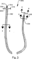
図3には外筒200のより詳細な図が示されている。外筒200は、外筒200の外面に沿って配置された1つ以上のインフレーションルーメン302を含んでいる。それらのインフレーションルーメン302は、外筒200の遠位端に据えられた1つ以上の溝付きバルーン304と流体連絡している。1つ以上の溝付きバルーン304はシャフト部分200の支持を提供するために拡張可能であり、さらにまた血管を閉塞するために使用することができる。
A more detailed view of the
外筒200の他方の端には、近位ハブ306が取り付けられている。ハブ306は外筒200のガイドルーメン400(図4Aで最も明らか)と流体連絡しているフラッシュポート308及びインフレーションルーメン302と流体連絡しているバルーンインフレーションポート310を含むことができる。外筒200と軸方向に整合しているハブ306には、さらにガイドポート312も取り付けられている。ガイドポート312は、外筒200内へのスタイレット204の導入を可能にする。ガイドポート312はさらにまた、回転型止血バルブ(RHV)などのデバイスを取り付けるのに適合するねじ切り部分314を有していてよい。
A
ハブ306及び外筒200は、使用時に外筒200を引き剥がすことを可能にする機構を備えて製造することができる。これは、典型的にはハブ306を分割可能にすると共に、外筒200の長さに沿って何らかのタイプのピーリング機構を提供することによって達成される。そのようなピーリング機構は、プレストレス機構を形成する(例、ノッチを入れる、又は折り線を入れる)ことによって、又は相違する壁厚の領域が存在するように外筒200の壁を押出し成形することによって形成できる。
The
外筒200は、一般的には、近位端が遠位端より大きな径を有するようにテーパ付けされている。外筒200の遠位端は軟質の先端チップ320を含むことができる。先端チップ320は、別個に接着されても、又は外筒200の共押出しによって形成されてもよい。
The
外筒200の構造の詳細は、図4A−6の断面図から最も明らかである。図4Aは、外筒200の近位区間を示している。この例では、外筒200の外面の周囲に3本のインフレーションルーメン302が間隔をあけて配置されている。インフレーションルーメン302は、一般的にはガイドルーメン400より小さい。インナーライナー402は、ガイドルーメン400を取り囲んでいる。インナーライナー402は、好ましくはHDPEなどの比較的固い潤滑性材料から作製される。ガイドルーメンの壁404及びインフレーションルーメンの壁406は、LDPE又はPebax 55Dなどのより軟質の材料の押出成形の単一部品から形成できる。
Details of the structure of the
図4Bは、外筒200がピールアウェイされることを可能にしながらも均一な壁厚を提供する逃げ溝410が含まれている以外は、図4Aに示したレイアウトに類似するインフレーションルーメンのレイアウトを示している。この配置において、逃げ溝410は、ガイドルーメンの壁404がインフレーションルーメンの壁406に接合する個所での分離を推し進める傾向がある。図4Cでは、逃げ溝410が排除され、補強部412に取って代わられている。この配置において、補強部412は、インフレーションルーメン302間のどこかでガイドルーメンの壁404の分離を推し進める傾向がある。
FIG. 4B shows an inflation lumen layout similar to the layout shown in FIG. 4A, except that a
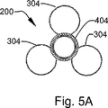
図5Aは、バルーン304での外筒200の断面図を示している。バルーン304(拡張した状態で示されている)は、別個に作製してガイドルーメンの壁404に取り付けられてよく、又は壁404と一体的に成形されてもよい。図5Aには3つのバルーンセグメント304が示されているが、所望される効果に応じて、任意の数のセグメントを使用できる。単一環状バルーン304は、それが挿入された血管のほぼ完全な閉塞を提供することになる。図5Aに示したような複数のバルーンセグメント304の使用は、部分的閉塞を提供できると共に、さらにまだ血管内における外筒200に安定化作用をもたらすことができる。
FIG. 5A shows a cross-sectional view of the
図5Bに示したように、各バルーンのローブの基部で肥厚領域502を形成するために余分な量の材料を成形でき、又は付加することができる。これらの肥厚領域504は、収縮した外筒200へ追加的に長手方向の硬さを提供し、外筒200の前進を容易にする。さらに肥厚領域502及びインフレーションルーメン302に沿った補強部/逃げ溝412、410は、ペーシングリードから外筒200を引きはがすのに役立つ「リップコード」を形成することになる。
As shown in FIG. 5B, an excess amount of material can be molded or added to form a thickened
図6は、先端チップ320での外筒200の断面図を示している。先端チップ320は、ガイドルーメンの壁404の上に接着された軟質のアウターカバー600によって形成することができる。軟質のアウターカバー600は、一般的にはガイドルーメンの壁404の材料と適合するデュロメーター硬さが低い材料である。あるいは、ガイドルーメンの壁404は、別個のアウターカバー600が先端チップ320を取り囲む必要がないように十分に軟質の材料から既に形成することもできる。
FIG. 6 shows a cross-sectional view of the
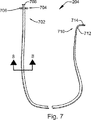
ここで図7を参照すると、本発明の1つの実施形態によるスタイレット204が示されている。スタイレット204の近位端702にはハブ704が取り付けられている。ハブ704は、近位端702でスタイレット204のトルク作用を可能にするために突出部(ウィング)706を含むことができる。スタイレットの近位端702にはルアー708もまた示されている。ルアー708は、ガイドワイヤーのアクセス及びスタイレット204をフラッシュするためにRHV型デバイスの接続を可能にする。あるいは、図3における外筒200上で示されているように、別個のフラッシュ用及びガイドワイヤー用ルアーを用意することもできる。
Referring now to FIG. 7, a
スタイレット204は、一般的には近位端702におけるより遠位端710において径が小さく且つより柔軟であるように設計されている。スタイレット204の遠位端710は、予備成形された屈曲部712及び軟質チップ714を含むことができる。予備成形された屈曲部712は、製造中にスタイレット内で熱硬化可能であってよい。軟質のチップ714は、好ましくは遠位端710が平滑な外側形状を維持するように成形されてよく、又はスタイレット204に接着されてもよい。
The
図8は、スタイレット204の断面を示している。スタイレット204は標準的なガイディングカテーテルの特徴を含むように構成することができ、通常は開口ルーメン804を取り囲んでいるインナーライナー802、編組コンポジット層806、及び外筒808を含んでいる。インナーライナー802及び外筒808は、潤滑性材料、典型的にはポリエチレン又はポリテトラフルオロエチレン(PTFE)から製造できる。編組コンポジット層806は、スタイレット204にねじれ硬さを提供するステンレススチール製ウーブンブレイドを含んでいる。コンポジット層806はブレード単独を含むことができる。又は、ブレードをプラスチック製チューブ内に成形し、これをインナーライナー802及び外筒808の間に挟んでもよい。コンポジット層のブレード角度及びコンポジット材料は、遠位端710におけるより近位端702においてより大きな硬さを提供すべく、スタイレット204の長さに沿って変動してよい。
FIG. 8 shows a cross section of the
ここで図9を参照すると、本発明の1つの実施形態によるガイドワイヤー210が示されている。ガイドワイヤーは可撓性を有する遠位区間902及びより剛性の高い近位区間904を有している。遠位区間902はループ状チップ906を有している。ループ状チップ906は、約2mmから7mmの範囲内の径を有している。ガイドワイヤー210は、ループ状チップ906が室温では直線状であり、体温では図示した形状を取るように遷移温度を備えるニチノールから製造することができる。
Referring now to FIG. 9, a
図10は、遠位端904Aで1つ以上の電気センサー1002を組み込んでいるガイドワイヤー210Aの代替実施形態を示している。電気センサー1002は通常は電極を含んでいるが、場合によっては、流量、温度、圧力などを測定するために熱電対又はマイクロエレクトロメカニカルシステム(MEMS)センサーなどの他のタイプのセンサーを使用できる。外部装置へセンサー1002を接続するために、近位端902Aには1つ以上の取り外し可能なリード1004が含まれている。
FIG. 10 illustrates an alternative embodiment of a
本発明によるガイドカテーテルシステムは、標的血管内、一般的には心血管内へのデバイスの配置を促進するために特に有用である。そのようなカテーテルシステムの特に適切な使用は、血管構造を通して冠状静脈洞内へペーシングリードを導入することである。ペーシングリードは、冠状静脈洞から心臓の左側にある静脈内に植え込まれる。ペーシングリードは、うっ血性心不全(CHF)を治療するために左心内に植え込まれることが多い。 The guide catheter system according to the present invention is particularly useful for facilitating the placement of the device within the target vessel, generally the cardiovascular. A particularly suitable use of such a catheter system is to introduce a pacing lead through the vasculature and into the coronary sinus. The pacing lead is implanted into the vein on the left side of the heart from the coronary sinus. A pacing lead is often implanted in the left heart to treat congestive heart failure (CHF).
ガイドカテーテルシステム100は、図1に示したようにペーシングリードを植え込むために冠状静脈洞にアクセスすることができる。1つのアプローチによると、外筒200及びスタイレット204は穿刺部もしくは切開部120を介して橈側皮静脈又は鎖骨下静脈などの比較的に大きなアクセス血管内に導入される。外筒200及びスタイレット204は、例えばアクセス血管を介して上大静脈106内に前進させることができ、それによって心臓の右心房104内に移動させられる。スタイレット204を外筒200内で操作して(例、回転させて)、外筒200の操縦および前進の向上を図ることができる。
図9に示したループ状チップを備えるガイドワイヤー210が使用される場合は、ガイドワイヤー210及びスタイレット204は、ガイドワイヤー210のループ状チップ906が心房104の壁を越えて移動するように一緒に操作される。ループ状チップ906は、冠状静脈洞108の静脈口を通過するときにこれを引っかけ、医師に触覚フィードバックを提供するように設計されている。静脈口の位置が決定されると、ガイドワイヤー210は、ループ状先端チップ906が血管壁に係合してワイヤー210を固定するまで冠状静脈洞108内を前進させられる。
If a
図10に示したセンサーチップ付きガイドワイヤー210Aが使用される場合は、リード1004がガイドワイヤー210Aの近位端に取り付けられ、適切な監視装置へ接続される(図示していない)。ガイドワイヤー210Aは心房壁に接触するまで前進させられ、そして電気信号を用いて冠状静脈洞108が位置すると思われる場所が決定される。ワイヤーが冠状静脈洞に進入すると、ワイヤーはガイドワイヤー210Aの先端チップを固定するために洞108内を前進させられる。
If the sensor
ガイドワイヤー210、210Aが適切に固定された後、外筒200は、外筒200が冠状静脈洞108に進入するまでスタイレット204及びガイドワイヤー210A上を前進させられる。必要であれば、スタイレット204を操作して冠状静脈洞108へのアクセスを改善する(例、回転させる)ことができる。まれではあるが、冠状静脈洞の静脈口にアクセスする上でより最適な形状のスタイレット204に置き換えるべく(外筒200及びガイドワイヤー210Aをその場所に残して)スタイレット204を交換することが必要になる場合がある。
After the
外筒200が冠状静脈洞108内に位置決めされると、1つ以上のバルーン304が拡張される。遠位バルーン304は、拡張されると2つの機能に役立つ。第1に、バルーン304は冠状静脈洞内に外筒200を固定する際に役立つ。第2に、バルーン304は血流を若干制限し、冠状静脈内への逆行性染料の注射の質を改善する。ローブ(lobe)形状のバルーン304を使用する場合、拡張したローブは冠状静脈洞108を完全には閉塞しないが、これは一部の状況では有利である。また、ローブ付きバルーン304の場合、バルーン区間を比較的長くすることが可能となり、外筒200の位置決めに要求される正確さが多少緩和される。
When the
1つ以上のバルーン304の拡張は、さらにまた外筒200の周囲に配列されたインフレーションルーメン302(図4で最も明らか)を加圧する上でも役立つ。インフレーションルーメン302の加圧は、外筒200の全体的剛性を増加させることになる(つまり、外筒200は時間可変性の剛性を備える外筒/シースとなる)。外筒200の増加した全体的剛性は、ペーシングリードが外筒200を介して前進させられるときの外筒200の性能を強化するであろう。追加の剛性が必要とされる場合は、インフレーションルーメン304が、小さなバルーンとして機能する様々な部分の薄い壁を有するように、外筒200を設計できる。これらの近位バルーンは、収縮した外筒200を硬化させずに、拡張した外筒の剛性を高める。
The expansion of one or
バルーン304が拡張され、それによって外筒200が安定化かつ硬化させられると、スタイレット204及びガイドワイヤー210、210Aを抜去することができる。ペーシングリード、及び所望であればより径の小さく、より可撓性の高いガイドワイヤーを次に外筒200内へ、そして冠状静脈洞に通して、冠状静脈内の適正な位置に挿入することができる。
Once the
当然ながら、上記で考察した好適実施形態には本発明の範囲から逸脱することなく様々な修正及び追加を加えてよいことを理解されたい。したがって、本発明の範囲は上述した特定実施形態によって限定されず、特許請求の範囲およびその均等物によってのみ規定される。 Of course, it should be understood that various modifications and additions may be made to the preferred embodiments discussed above without departing from the scope of the present invention. Accordingly, the scope of the invention is not limited by the specific embodiments described above, but is defined only by the claims and their equivalents.
Claims (11)
1つの外筒と、
1つのスタイレットと、を含み、
前記外筒が、1つの開口ガイドルーメンと、前記外筒の円筒外面から外側に突出するように前記外筒の円筒外面に沿って且つ該円筒外面に設けられた少なくとも1つのインフレーションルーメンと、該外筒の遠位部分に固定可能に取り付けられた遠位バルーンの少なくとも1つのセグメントであって、該遠位バルーンが該少なくとも1つのインフレーションルーメンと流体連絡しているセグメントと、を含み、
前記スタイレットは前記外筒のガイドルーメン内に配置され、該スタイレットは予備成形された遠位屈曲部を含み、該スタイレットは該外筒の長手軸に沿って該外筒内で回転可能であり、また、該スタイレットの該予備成形された遠位屈曲部は、該スタイレットの回転に伴って該外筒の長手軸の側方へ該外筒を偏向させる寸法に作られていることを特徴とするガイディングカテーテルシステム。A guiding catheter system for accessing a patient's heart,
One outer cylinder,
One stylet, and
The outer cylinder has one opening guide lumen, and at least one inflation lumen provided along the cylindrical outer surface of the outer cylinder so as to protrude outward from the cylindrical outer surface of the outer cylinder; and At least one segment of a distal balloon fixedly attached to a distal portion of the outer tube, wherein the distal balloon is in fluid communication with the at least one inflation lumen;
The stylet is disposed within a guide lumen of the outer cylinder, the stylet includes a preformed distal bend, and the stylet is rotatable within the outer cylinder along a longitudinal axis of the outer cylinder. And the preformed distal bend of the stylet is dimensioned to deflect the outer cylinder to the side of the outer cylinder longitudinal axis as the stylet rotates. A guiding catheter system characterized by that.
Applications Claiming Priority (3)
| Application Number | Priority Date | Filing Date | Title |
|---|---|---|---|
| US10/351,718 US6928313B2 (en) | 2003-01-27 | 2003-01-27 | System and method for accessing the coronary sinus to facilitate insertion of pacing leads |
| US10/351,718 | 2003-01-27 | ||
| PCT/US2004/002088 WO2004067078A2 (en) | 2003-01-27 | 2004-01-27 | System for accessing the coronary sinus to facilitate insertion of pacing leads |
Publications (3)
| Publication Number | Publication Date |
|---|---|
| JP2006516451A JP2006516451A (en) | 2006-07-06 |
| JP2006516451A5 JP2006516451A5 (en) | 2007-03-15 |
| JP4722033B2 true JP4722033B2 (en) | 2011-07-13 |
Family
ID=32735838
Family Applications (1)
| Application Number | Title | Priority Date | Filing Date |
|---|---|---|---|
| JP2006503019A Expired - Fee Related JP4722033B2 (en) | 2003-01-27 | 2004-01-27 | System and method for accessing the coronary sinus to facilitate insertion of a pacing lead |
Country Status (6)
| Country | Link |
|---|---|
| US (2) | US6928313B2 (en) |
| EP (1) | EP1587571B1 (en) |
| JP (1) | JP4722033B2 (en) |
| AT (1) | ATE370762T1 (en) |
| DE (1) | DE602004008425T2 (en) |
| WO (1) | WO2004067078A2 (en) |
Families Citing this family (68)
| Publication number | Priority date | Publication date | Assignee | Title |
|---|---|---|---|---|
| JP3358208B2 (en) * | 1992-07-28 | 2002-12-16 | ソニー株式会社 | Video and electronic equipment |
| US20040158229A1 (en) * | 2002-01-24 | 2004-08-12 | Quinn David G. | Catheter assembly and method of catheter insertion |
| US8920432B2 (en) | 2002-09-24 | 2014-12-30 | Medtronic, Inc. | Lead delivery device and method |
| US9849279B2 (en) * | 2008-06-27 | 2017-12-26 | Medtronic, Inc. | Lead delivery device and method |
| US9480839B2 (en) * | 2002-09-24 | 2016-11-01 | Medtronic, Inc. | Lead delivery device and method |
| US8229572B2 (en) * | 2008-06-27 | 2012-07-24 | Medtronic, Inc. | Lead delivery device and method |
| US9636499B2 (en) * | 2002-09-24 | 2017-05-02 | Medtronic, Inc. | Lead delivery device and method |
| US20050131505A1 (en) * | 2003-12-10 | 2005-06-16 | Japan General Medical Institute Co., Ltd. | Lead insertion support device |
| US7181290B2 (en) * | 2004-03-12 | 2007-02-20 | Pacesetter, Inc. | Convertible stylet to abet in the implant of a left heart lead |
| US20060195135A1 (en) * | 2005-02-25 | 2006-08-31 | Ihab Ayoub | Pass-through catheter |
| US7962208B2 (en) | 2005-04-25 | 2011-06-14 | Cardiac Pacemakers, Inc. | Method and apparatus for pacing during revascularization |
| US9616223B2 (en) * | 2005-12-30 | 2017-04-11 | Medtronic, Inc. | Media-exposed interconnects for transducers |
| US7747334B2 (en) * | 2006-03-23 | 2010-06-29 | Cardiac Pacemakers, Inc. | Left ventricular lead shapes |
| US8348889B2 (en) * | 2006-06-01 | 2013-01-08 | Arash Salemi | Self-retaining and fluid delivery catheter |
| US20080071315A1 (en) * | 2006-08-31 | 2008-03-20 | Tamara Colette Baynham | Integrated catheter and pulse generator systems and methods |
| US8337518B2 (en) | 2006-12-20 | 2012-12-25 | Onset Medical Corporation | Expandable trans-septal sheath |
| US10166066B2 (en) | 2007-03-13 | 2019-01-01 | University Of Virginia Patent Foundation | Epicardial ablation catheter and method of use |
| US11058354B2 (en) | 2007-03-19 | 2021-07-13 | University Of Virginia Patent Foundation | Access needle with direct visualization and related methods |
| US9468396B2 (en) | 2007-03-19 | 2016-10-18 | University Of Virginia Patent Foundation | Systems and methods for determining location of an access needle in a subject |
| WO2008115745A2 (en) | 2007-03-19 | 2008-09-25 | University Of Virginia Patent Foundation | Access needle pressure sensor device and method of use |
| US9211405B2 (en) | 2007-03-22 | 2015-12-15 | University Of Virginia Patent Foundation | Electrode catheter for ablation purposes and related method thereof |
| US20100241185A1 (en) | 2007-11-09 | 2010-09-23 | University Of Virginia Patent Foundation | Steerable epicardial pacing catheter system placed via the subxiphoid process |
| US8728153B2 (en) | 2008-05-14 | 2014-05-20 | Onset Medical Corporation | Expandable transapical sheath and method of use |
| US8562559B2 (en) | 2008-05-14 | 2013-10-22 | Onset Medical Corporation | Expandable iliac sheath and method of use |
| US8668668B2 (en) | 2008-05-14 | 2014-03-11 | Onset Medical Corporation | Expandable iliac sheath and method of use |
| US11931523B2 (en) | 2008-06-27 | 2024-03-19 | Medtronic, Inc. | Lead delivery device and method |
| US9775989B2 (en) * | 2008-06-27 | 2017-10-03 | Medtronic, Inc. | Lead delivery device and method |
| US9775990B2 (en) * | 2008-06-27 | 2017-10-03 | Medtronic, Inc. | Lead delivery device and method |
| US9913964B2 (en) * | 2008-12-29 | 2018-03-13 | Acclarnet, Inc. | System and method for dilating an airway stenosis |
| US8403877B2 (en) * | 2009-07-01 | 2013-03-26 | E2 Llc | Systems and methods for treatment of obesity and type 2 diabetes |
| US9642534B2 (en) | 2009-09-11 | 2017-05-09 | University Of Virginia Patent Foundation | Systems and methods for determining location of an access needle in a subject |
| EP2537149B1 (en) | 2010-02-18 | 2017-10-25 | University Of Virginia Patent Foundation | System, method, and computer program product for simulating epicardial electrophysiology procedures |
| US10111768B1 (en) | 2010-03-01 | 2018-10-30 | Mwest, Llc | System, method and apparatus for placing therapeutic devices in a heart |
| US9033996B1 (en) * | 2010-03-01 | 2015-05-19 | Michael B. West | System, method and apparatus for placing therapeutic devices in a heart |
| US20110251595A1 (en) * | 2010-04-07 | 2011-10-13 | Kassab Kughn Endovascular Devices Llc | Endovascular catheter and method with hydraulic bladder system |
| WO2014066439A1 (en) | 2012-10-22 | 2014-05-01 | Medtronic Ardian Luxembourg Sarl | Catheters with enhanced flexibility |
| US9044575B2 (en) | 2012-10-22 | 2015-06-02 | Medtronic Adrian Luxembourg S.a.r.l. | Catheters with enhanced flexibility and associated devices, systems, and methods |
| US20140121642A1 (en) * | 2012-10-25 | 2014-05-01 | Boston Scientific Scimed, Inc. | Dual function medical devices |
| WO2014078494A1 (en) * | 2012-11-15 | 2014-05-22 | Cardiac Pacemakers, Inc. | Guide catheter occlusion balloon with active inflation |
| EP2996754B1 (en) | 2013-05-18 | 2023-04-26 | Medtronic Ardian Luxembourg S.à.r.l. | Neuromodulation catheters with shafts for enhanced flexibility and control and associated devices and systems |
| US9572666B2 (en) | 2014-03-17 | 2017-02-21 | Evalve, Inc. | Mitral valve fixation device removal devices and methods |
| SG11201609071SA (en) | 2014-06-17 | 2016-11-29 | Biotronik Se & Co Kg | Elongated guide sheath |
| EP3274038A4 (en) | 2015-03-27 | 2019-02-27 | Project Moray, Inc. | Articulation systems, devices, and methods for catheters and other uses |
| US10376673B2 (en) | 2015-06-19 | 2019-08-13 | Evalve, Inc. | Catheter guiding system and methods |
| US10525233B2 (en) | 2015-12-04 | 2020-01-07 | Project Moray, Inc. | Input and articulation system for catheters and other uses |
| WO2017096362A1 (en) | 2015-12-04 | 2017-06-08 | Barrish Mark D | Lateral articulation anchors for catheters and other uses |
| WO2017143170A1 (en) | 2016-02-17 | 2017-08-24 | Keith Phillip Laby | Local contraction of flexible bodies using balloon expansion for extension-contraction catheter articulation and other uses |
| WO2017165810A1 (en) | 2016-03-25 | 2017-09-28 | Phillip Laby | Fluid-actuated sheath displacement and articulation behavior improving systems, devices, and methods for catheters, continuum manipulators, and other uses |
| US11420021B2 (en) | 2016-03-25 | 2022-08-23 | Project Moray, Inc. | Fluid-actuated displacement for catheters, continuum manipulators, and other uses |
| US10736632B2 (en) | 2016-07-06 | 2020-08-11 | Evalve, Inc. | Methods and devices for valve clip excision |
| US10661052B2 (en) | 2016-07-29 | 2020-05-26 | Cephea Valve Technologies, Inc. | Intravascular device delivery sheath |
| US11324495B2 (en) | 2016-07-29 | 2022-05-10 | Cephea Valve Technologies, Inc. | Systems and methods for delivering an intravascular device to the mitral annulus |
| US10974027B2 (en) | 2016-07-29 | 2021-04-13 | Cephea Valve Technologies, Inc. | Combination steerable catheter and systems |
| US10639151B2 (en) | 2016-07-29 | 2020-05-05 | Cephea Valve Technologies, Inc. | Threaded coil |
| US10646689B2 (en) | 2016-07-29 | 2020-05-12 | Cephea Valve Technologies, Inc. | Mechanical interlock for catheters |
| US10933216B2 (en) | 2016-08-29 | 2021-03-02 | Cephea Valve Technologies, Inc. | Multilumen catheter |
| US11045315B2 (en) | 2016-08-29 | 2021-06-29 | Cephea Valve Technologies, Inc. | Methods of steering and delivery of intravascular devices |
| US10751485B2 (en) | 2016-08-29 | 2020-08-25 | Cephea Valve Technologies, Inc. | Methods, systems, and devices for sealing and flushing a delivery system |
| US11109967B2 (en) | 2016-08-29 | 2021-09-07 | Cephea Valve Technologies, Inc. | Systems and methods for loading and deploying an intravascular device |
| US11369432B2 (en) | 2016-09-28 | 2022-06-28 | Project Moray, Inc. | Arrhythmia diagnostic and/or therapy delivery methods and devices, and robotic systems for other uses |
| WO2018064400A1 (en) | 2016-09-28 | 2018-04-05 | Project Moray, Inc. | Base station, charging station, and/or server for robotic catheter systems and other uses, and improved articulated devices and systems |
| US11071564B2 (en) | 2016-10-05 | 2021-07-27 | Evalve, Inc. | Cardiac valve cutting device |
| US10874512B2 (en) | 2016-10-05 | 2020-12-29 | Cephea Valve Technologies, Inc. | System and methods for delivering and deploying an artificial heart valve within the mitral annulus |
| US10363138B2 (en) | 2016-11-09 | 2019-07-30 | Evalve, Inc. | Devices for adjusting the curvature of cardiac valve structures |
| WO2018200537A1 (en) | 2017-04-25 | 2018-11-01 | Project Moray, Inc. | Matrix supported balloon articulation systems, devices, and methods for catheters and other users |
| US11905286B2 (en) | 2018-08-09 | 2024-02-20 | Antabio Sas | Diazabicyclooctanones as inhibitors of serine beta-lactamases |
| US11724068B2 (en) | 2018-11-16 | 2023-08-15 | Cephea Valve Technologies, Inc. | Intravascular delivery system |
| WO2023112984A1 (en) * | 2021-12-17 | 2023-06-22 | ニプロ株式会社 | Catheter |
Citations (3)
| Publication number | Priority date | Publication date | Assignee | Title |
|---|---|---|---|---|
| US4917104A (en) * | 1988-06-10 | 1990-04-17 | Telectronics Pacing Systems, Inc. | Electrically insulated "J" stiffener wire |
| US5993424A (en) * | 1996-08-05 | 1999-11-30 | Cordis Corporation | Guidewire having a distal tip that can change its shape within a vessel |
| WO2001000268A1 (en) * | 1999-06-25 | 2001-01-04 | Daig Corporation | Splittable occlusion balloon sheath and process of use |
Family Cites Families (18)
| Publication number | Priority date | Publication date | Assignee | Title |
|---|---|---|---|---|
| US5151100A (en) * | 1988-10-28 | 1992-09-29 | Boston Scientific Corporation | Heating catheters |
| US5179961A (en) | 1989-04-13 | 1993-01-19 | Littleford Philip O | Catheter guiding and positioning method |
| US4983165A (en) | 1990-01-23 | 1991-01-08 | Loiterman David A | Guidance system for vascular catheter or the like |
| US6029671A (en) * | 1991-07-16 | 2000-02-29 | Heartport, Inc. | System and methods for performing endovascular procedures |
| US5584803A (en) * | 1991-07-16 | 1996-12-17 | Heartport, Inc. | System for cardiac procedures |
| US5318527A (en) * | 1992-12-22 | 1994-06-07 | Advanced Cardiovascular Systems, Inc. | Fixed wire catheter exchange device |
| US5462529A (en) | 1993-09-29 | 1995-10-31 | Technology Development Center | Adjustable treatment chamber catheter |
| US5571161A (en) | 1995-04-12 | 1996-11-05 | Starksen; Niel F. | Apparatus and method for implanting electrical leads in the heart |
| EP0836499A1 (en) | 1995-06-07 | 1998-04-22 | Cardima, Inc. | Guiding catheter for coronary sinus |
| US5807324A (en) | 1996-04-01 | 1998-09-15 | Procath Corporation | Steerable catheter |
| US5971983A (en) * | 1997-05-09 | 1999-10-26 | The Regents Of The University Of California | Tissue ablation device and method of use |
| US6024740A (en) | 1997-07-08 | 2000-02-15 | The Regents Of The University Of California | Circumferential ablation device assembly |
| US6168586B1 (en) * | 1998-08-07 | 2001-01-02 | Embol-X, Inc. | Inflatable cannula and method of using same |
| US6290697B1 (en) | 1998-12-01 | 2001-09-18 | Irvine Biomedical, Inc. | Self-guiding catheter system for tissue ablation |
| US6122552A (en) | 1999-03-03 | 2000-09-19 | Cardiac Pacemakers, Inc. | Insertion apparatus for left ventricular access lead |
| US6287319B1 (en) | 1999-03-30 | 2001-09-11 | Amed Systems, Inc. | Cannula with balloon tip |
| US6733500B2 (en) * | 2000-03-31 | 2004-05-11 | Medtronic, Inc. | Method and system for delivering a medical electrical lead within a venous system |
| US7503904B2 (en) * | 2002-04-25 | 2009-03-17 | Cardiac Pacemakers, Inc. | Dual balloon telescoping guiding catheter |
-
2003
- 2003-01-27 US US10/351,718 patent/US6928313B2/en not_active Expired - Fee Related
-
2004
- 2004-01-27 AT AT04705579T patent/ATE370762T1/en not_active IP Right Cessation
- 2004-01-27 JP JP2006503019A patent/JP4722033B2/en not_active Expired - Fee Related
- 2004-01-27 WO PCT/US2004/002088 patent/WO2004067078A2/en active IP Right Grant
- 2004-01-27 DE DE602004008425T patent/DE602004008425T2/en not_active Expired - Lifetime
- 2004-01-27 EP EP04705579A patent/EP1587571B1/en not_active Expired - Lifetime
-
2005
- 2005-07-15 US US11/183,050 patent/US7570981B2/en not_active Expired - Fee Related
Patent Citations (3)
| Publication number | Priority date | Publication date | Assignee | Title |
|---|---|---|---|---|
| US4917104A (en) * | 1988-06-10 | 1990-04-17 | Telectronics Pacing Systems, Inc. | Electrically insulated "J" stiffener wire |
| US5993424A (en) * | 1996-08-05 | 1999-11-30 | Cordis Corporation | Guidewire having a distal tip that can change its shape within a vessel |
| WO2001000268A1 (en) * | 1999-06-25 | 2001-01-04 | Daig Corporation | Splittable occlusion balloon sheath and process of use |
Also Published As
| Publication number | Publication date |
|---|---|
| US20050251094A1 (en) | 2005-11-10 |
| JP2006516451A (en) | 2006-07-06 |
| WO2004067078A2 (en) | 2004-08-12 |
| EP1587571B1 (en) | 2007-08-22 |
| ATE370762T1 (en) | 2007-09-15 |
| DE602004008425T2 (en) | 2008-05-15 |
| WO2004067078A3 (en) | 2004-09-10 |
| DE602004008425D1 (en) | 2007-10-04 |
| US20040147826A1 (en) | 2004-07-29 |
| EP1587571A2 (en) | 2005-10-26 |
| US7570981B2 (en) | 2009-08-04 |
| US6928313B2 (en) | 2005-08-09 |
Similar Documents
| Publication | Publication Date | Title |
|---|---|---|
| JP4722033B2 (en) | System and method for accessing the coronary sinus to facilitate insertion of a pacing lead | |
| US7824391B2 (en) | Articulating guide catheter | |
| US7503904B2 (en) | Dual balloon telescoping guiding catheter | |
| US6706018B2 (en) | Adjustable length catheter assembly | |
| US7493156B2 (en) | Steerable guide catheter with pre-shaped rotatable shaft | |
| US6979319B2 (en) | Telescoping guide catheter with peel-away outer sheath | |
| US8753312B2 (en) | Inner and outer telescoping catheter delivery system | |
| US6612999B2 (en) | Balloon actuated guide catheter | |
| US6544215B1 (en) | Steerable device for introducing diagnostic and therapeutic apparatus into the body | |
| US6953454B2 (en) | Methods of using a deflectable telescoping guide catheter | |
| US6126649A (en) | Steerable catheter with external guidewire as catheter tip deflector | |
| US20040215228A1 (en) | Compliant guiding catheter sheath system | |
| JP3820270B2 (en) | Intra-aortic balloon catheter | |
| US20200330664A1 (en) | Variable-stiffness distal extension for a blood pump system |
Legal Events
| Date | Code | Title | Description |
|---|---|---|---|
| A521 | Request for written amendment filed |
Free format text: JAPANESE INTERMEDIATE CODE: A523 Effective date: 20070126 |
|
| A621 | Written request for application examination |
Free format text: JAPANESE INTERMEDIATE CODE: A621 Effective date: 20070126 |
|
| RD02 | Notification of acceptance of power of attorney |
Free format text: JAPANESE INTERMEDIATE CODE: A7422 Effective date: 20090309 |
|
| RD03 | Notification of appointment of power of attorney |
Free format text: JAPANESE INTERMEDIATE CODE: A7423 Effective date: 20090309 |
|
| RD04 | Notification of resignation of power of attorney |
Free format text: JAPANESE INTERMEDIATE CODE: A7424 Effective date: 20090317 |
|
| A131 | Notification of reasons for refusal |
Free format text: JAPANESE INTERMEDIATE CODE: A131 Effective date: 20090721 |
|
| A601 | Written request for extension of time |
Free format text: JAPANESE INTERMEDIATE CODE: A601 Effective date: 20091021 |
|
| A602 | Written permission of extension of time |
Free format text: JAPANESE INTERMEDIATE CODE: A602 Effective date: 20091028 |
|
| A521 | Request for written amendment filed |
Free format text: JAPANESE INTERMEDIATE CODE: A523 Effective date: 20091110 |
|
| A131 | Notification of reasons for refusal |
Free format text: JAPANESE INTERMEDIATE CODE: A131 Effective date: 20100531 |
|
| A601 | Written request for extension of time |
Free format text: JAPANESE INTERMEDIATE CODE: A601 Effective date: 20100831 |
|
| A602 | Written permission of extension of time |
Free format text: JAPANESE INTERMEDIATE CODE: A602 Effective date: 20100907 |
|
| A521 | Request for written amendment filed |
Free format text: JAPANESE INTERMEDIATE CODE: A523 Effective date: 20100930 |
|
| TRDD | Decision of grant or rejection written | ||
| A01 | Written decision to grant a patent or to grant a registration (utility model) |
Free format text: JAPANESE INTERMEDIATE CODE: A01 Effective date: 20110328 |
|
| A01 | Written decision to grant a patent or to grant a registration (utility model) |
Free format text: JAPANESE INTERMEDIATE CODE: A01 |
|
| A61 | First payment of annual fees (during grant procedure) |
Free format text: JAPANESE INTERMEDIATE CODE: A61 Effective date: 20110405 |
|
| FPAY | Renewal fee payment (event date is renewal date of database) |
Free format text: PAYMENT UNTIL: 20140415 Year of fee payment: 3 |
|
| R150 | Certificate of patent or registration of utility model |
Free format text: JAPANESE INTERMEDIATE CODE: R150 |
|
| R250 | Receipt of annual fees |
Free format text: JAPANESE INTERMEDIATE CODE: R250 |
|
| LAPS | Cancellation because of no payment of annual fees |