WO2023112984A1 - Catheter - Google Patents
Catheter Download PDFInfo
- Publication number
- WO2023112984A1 WO2023112984A1 PCT/JP2022/046207 JP2022046207W WO2023112984A1 WO 2023112984 A1 WO2023112984 A1 WO 2023112984A1 JP 2022046207 W JP2022046207 W JP 2022046207W WO 2023112984 A1 WO2023112984 A1 WO 2023112984A1
- Authority
- WO
- WIPO (PCT)
- Prior art keywords
- stylet
- catheter
- tip
- distal end
- lumen
- Prior art date
Links
Images


Classifications
-
- A—HUMAN NECESSITIES
- A61—MEDICAL OR VETERINARY SCIENCE; HYGIENE
- A61M—DEVICES FOR INTRODUCING MEDIA INTO, OR ONTO, THE BODY; DEVICES FOR TRANSDUCING BODY MEDIA OR FOR TAKING MEDIA FROM THE BODY; DEVICES FOR PRODUCING OR ENDING SLEEP OR STUPOR
- A61M25/00—Catheters; Hollow probes
- A61M25/01—Introducing, guiding, advancing, emplacing or holding catheters
Definitions
- the present disclosure relates to a peripherally inserted central venous catheter.
- a peripheral vein insertion type central venous catheter is used, which is inserted from a peripheral vein such as an upper arm and positioned at a central vein near the heart at the time of infusion or the like. Since PICC can deliver drugs to thick blood vessels near the heart, phlebitis and the like due to drugs are less likely to occur.
- PICC central vein insertion type central venous catheter
- the catheter itself is made relatively soft and combined with a guide wire or stylet to provide the necessary stiffness for insertion and pushing.
- the Seldinger method in which the guidewire is first indwelled in the blood vessel, and the catheter is inserted into the blood vessel along the inserted guidewire.
- the total length of the guide wire is as high as about 150 cm, and the total length of the catheter is also as high as about 60 cm. Therefore, in the case of PICC, the technique of the Seldinger method is complicated.
- the tip of the stylet should not protrude from the catheter so as not to damage the inner wall of the blood vessel.
- the catheter tip directly contacts the inner wall of the vessel.
- a catheter made of resin is soft, but if it has an edge at its tip, it may damage the inner wall of the blood vessel by contact.
- the length of the catheter may be adjusted by severing the tip, which presents a sharp edge at the tip and thus risks perforation.
- Patent Document 1 discloses a stylet for a central venous catheter having a bending portion made of synthetic resin at its tip.
- the bent portion is made of a synthetic resin that is softer than metal, so it is expected that even if the distal end including the bent portion protrudes from the distal end of the catheter, the inner wall of the blood vessel can be prevented from being damaged. be done.
- the stylet of Patent Document 1 has a maximum length of about 20 cm. Therefore, in the case of a centrally inserted central venous catheter to be inserted into a large vein, the stylet described in Patent Document 1 can be used. However, it is difficult to use such a stylet in PICC, which is longer than the above-mentioned catheter and is inserted from a narrow peripheral blood vessel.
- the present disclosure makes it possible to realize a PICC that has the necessary stiffness for insertion and can suppress the risk of perforation of the inner wall of the blood vessel.
- one aspect of the catheter disclosed herein is a peripheral vein insertion type central vein catheter, comprising a catheter body and a stylet inserted through the catheter body,
- the stylet has a tip that is softer than the rest of the stylet and has a projection projecting from the distal end of the catheter body.
- the stylet is inserted into the catheter body and inserted into the blood vessel. Therefore, it is possible to omit the troublesome operation of inserting the catheter main body after inserting the guide wire into the blood vessel first, and to ensure the necessary stiffness and resistance to breakage when inserting the catheter.
- the protruding portion of the stylet protrudes from the distal end of the catheter body, the protruding portion serves as a guide during insertion of the catheter, reducing the risk of perforation of the blood vessel.
- the tip of the stylet is more flexible than the rest of the stylet, the risk of damaging the blood vessel with the tip of the stylet can be reduced.
- the stylet has a core made of a metal wire, and the diameter of the tip of the core is smaller than the diameter of the rest of the core.
- the flexibility of the tip of the stylet can be adjusted by adjusting the diameter of the core material, the risk of perforation of the blood vessel can be effectively reduced while sufficiently ensuring necessary stiffness and resistance to breakage. can be provided in a convenient manner.
- the tip of the stylet may have a coil shape.
- the stylet includes a resin layer covering the core material, and that the outer diameter of the stylet is substantially constant over the entire length of the core material.
- the resin layer is thicker at the tip portion of the stylet than at the other portion of the stylet.
- the outer diameter of the stylet is substantially constant over the entire length of the core. According to this configuration, it is possible to ensure sufficient flexibility at the distal end of the stylet and sufficient strength of the entire stylet.
- substantially constant outer diameter means that the difference between the outer diameter and the maximum outer diameter is within 20% of the maximum outer diameter.
- the length of the projecting portion of the stylet is preferably 10 mm or more and 50 mm or less.
- the tip of the catheter body may come into contact with the inner wall of the blood vessel if the stylet bends slightly. If the length of the protruding portion of the stylet exceeds the upper limit, the tip of the catheter body may inadvertently enter, for example, the heart when the catheter is placed in a blood vessel. There is a possibility that it will not be placed in position.
- the length of the catheter body is preferably 40 cm or longer.
- the present disclosure it is possible to omit the complicated operation of inserting the catheter main body after inserting the guide wire into the blood vessel first, and to provide the necessary stiffness and resistance to breakage when inserting the catheter. can be secured.
- the projecting portion of the stylet serves as a guide when inserting the catheter, and the risk of perforation of the blood vessel can be reduced.
- the tip of the stylet is more flexible than the rest of the stylet, the risk of damaging the blood vessel with the tip of the stylet can be reduced.
- FIG. 2 illustrates a catheter according to one embodiment
- FIG. 2 is a cross-sectional view taken along line AA of FIG. 1
- Fig. 10 shows a stylet
- 4 is a cross-sectional view of the stylet body
- FIG. 1 is a schematic diagram of the apparatus used for the tip load measurement test
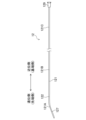
- FIG. 1 is a general view of a peripherally inserted central venous catheter 1 according to an embodiment of the present disclosure.
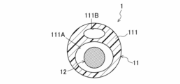
- FIG. 2 is a cross-sectional view taken along line AA of FIG.
- the catheter 1 includes a catheter body 11 and a stylet 12 inserted through the catheter body 11.
- the catheter body 11 is a tubular member having a double lumen structure. Note that the catheter body 11 is not limited to the double lumen structure, and may have a single lumen structure, a triple lumen structure, or the like.
- the length of the catheter body 11 can be appropriately set in consideration of the length from the catheter insertion site such as a human extremity or coronary artery to the affected area. It has a length from the apex to the affected part of the superior vena cava. Specifically, the length of the catheter body 11 is preferably 40 cm or longer.
- the catheter body 11 includes a shaft 111, a distal tip 112, a Y tube portion 113, a first branch tube 114 and a second branch tube 115, a first port 114A and a second port 115A. , a first clamp 114B and a second clamp 115B.
- the shaft 111 is a flexible, elongated tube, and as shown in FIG. 2, has a first lumen 111A and a second lumen 111B that are independent passages.
- a side-hole type opening 111C is provided on the distal end side of the shaft 111 .
- the second lumen 111B opens at the opening 111C.
- the specific structure of the shaft 111 is not particularly limited.
- the shaft 111 may be made of one or more biocompatible resin materials such as polyurethane, polyethylene, polyester, polypropylene, polyether block amide, polyamide, polytetrafluoroethylene, and polyvinylidene fluoride.
- the shaft 111 may be formed of a single layer of the resin material, or may be formed of multiple layers.
- the shaft 111 is formed of a plurality of layers of the resin material, and a mesh-like cylindrical braided body made of metal such as stainless steel or Ni—Ti alloy or resin is embedded between the layers. A laminated structure or the like may also be used.
- the shaft 111 may be divided into a plurality of sections in the longitudinal direction, and different resin materials may be used for each of the plurality of sections.
- the distal end side portion of the shaft 111 may be formed using a material that is more flexible than the proximal end side portion.
- a contrast agent such as bismuth oxide, bismuth sulfate, bismuth subcarbonate, or tungsten may be added to the molding resin layer of the shaft 111, or stainless steel, gold, platinum, or the like may be added to the outer peripheral surface of the shaft 111 or between layers. Contrast markers or the like made of iridium or the like may be provided. As a result, it is possible to secure visibility with X-rays during surgery.
- the distal tip 112 is a tubular member provided at the distal end of the shaft 111 and constitutes the distal end of the catheter body 11 .
- the proximal end of the distal tip 112 has substantially the same outer and inner diameter dimensions as the distal end of the shaft 111 and is integrally connected with the distal end of the shaft 111 .
- the proximal end of the lumen of the distal tip 112 communicates with the first lumen 111A, and the distal end forms an endhole-shaped opening 112A (the distal end of the catheter main body).
- the distal tip 112 may be integrally molded with the shaft 111, or may be formed separately from an appropriate resin material and fixed to the distal end of the shaft 111 by adhesion, welding, or the like. Distal tip 112 may be formed of a single layer or multiple layers of the same material as shaft 111 . Note that the distal tip 112 is preferably made of a material that is more flexible than the shaft 111 from the viewpoint of reducing the risk of blood vessel perforation.
- a contrast agent may be blended in the molding material, or a contrast marker or the like may be provided on the outer peripheral surface or between the layers. This allows the distal end of the catheter body 11 to be visually recognized under X-ray fluoroscopy.
- the Y tube portion 113 is provided at the proximal end of the shaft 111 and is a tubular member having two independent lumens that are continuous with each of the first lumen 111A and the second lumen 111B.
- the Y tube part 113 is a resin molded body such as polyurethane, and can serve as a handle for inserting and removing the catheter 1, for example.
- the first branch tube 114 and the second branch tube 115 are tubular members connected to the proximal end of the Y tube portion 113 .
- the lumen of the first branch tube 114 communicates with the lumen of the Y tube portion 113 connected to the first lumen 111A.
- a first port 114A is provided at the proximal end of the first branch tube 114 .
- a first clamp 114B is provided between the Y tube portion 113 and the first port 114A of the first branch tube 114 .
- the lumen of the second branch tube 115 communicates with the lumen of the Y tube portion 113 connected to the second lumen 111B.
- the proximal end of the second branch tube 115 is provided with a second port 115A.
- a second clamp 115B is provided between the Y tube portion 113 of the second branch tube 115 and the second port 115A.
- a proximal lumen is formed by the second lumen 111B of the shaft 111, the lumen of the Y tube portion 113 connected to the second lumen 111B, and the lumens of the second branch tube 115 and the second port 115A.
- the catheter 1 is of an over-the-wire type, and the stylet 12 is passed through the distal lumen through the first port 114A. That is, the inner diameter of the distal lumen is set to a diameter that allows the stylet 12 to be inserted.
- a low-friction resin such as PTFE (polytetrafluoroethylene) may be applied to the inner peripheral surface of each member constituting the distal lumen. As a result, the coefficient of friction of the inner peripheral surface can be reduced, so that the insertability of the stylet 12 is improved.
- the proximal lumen is a space through which fluids such as a contrast medium, physiological saline, and air can flow.
- catheter 1 is not limited to the over-the-wire type, and may have other known structures such as a rapid exchange type.
- the catheter 1 is inserted into a blood vessel with the stylet 12 inserted into the distal lumen of the catheter main body 11 and a protruding portion 122 described later protruding from the opening 112A. That is, the stylet 12 is longer than at least the distal lumen of the catheter body 11 .
- the stylet 12 has a stylet body 121 and a protective member 129. As shown in FIGS. 1 and 3, the stylet 12 has a stylet body 121 and a protective member 129. As shown in FIGS. 1 and 3, the stylet 12 has a stylet body 121 and a protective member 129. As shown in FIGS. 1 and 3, the stylet 12 has a stylet body 121 and a protective member 129. As shown in FIGS.
- the protective member 129 is provided at the proximal end of the stylet body 121 and constitutes the proximal end of the stylet 12 .
- the protective member 129 is, for example, a columnar or plate-like member that is gripped by the operator to operate the stylet 12 .
- the protective member 129 is made of, for example, polypropylene, polycarbonate, vinyl chloride, or the like.
- the stylet main body 121 is a wire material having a higher rigidity than the shaft 111, and has a certain degree of elasticity so that it can be held in its original shape and can be restored to its original shape even after being deformed. As a result, the necessary stiffness and resistance to breakage when inserting the catheter 1 can be ensured.
- the outer diameter dimension of the stylet body 121 is set sufficiently smaller than the inner diameter dimension of the distal lumen.
- the length of stylet body 121 is configured such that the overall length of stylet 12 is longer than the distal lumen of catheter body 11 .
- the stylet body 121 includes a core material 123 and a resin layer 125 covering the core material 123 .
- the core material 123 is made of metal wire such as stainless steel or Ni--Ti alloy.
- the resin layer 125 is made of fluorine resin such as PTFE, PFA (tetrafluoroethylene-perfluoroalkyl vinyl ether copolymer), ETFE (ethylene-tetrafluoroethylene copolymer), polyurethane, hydrophilic coating, or the like.
- the resin layer 125 is provided to ensure slipperiness when the stylet 12 is passed through the distal lumen, but may not be provided.
- the core material 123 may be formed of a metal having contrast enhancement properties.
- a contrast marker may be provided between the core material 123 and the resin layer 125 . This allows the stylet 12 to be visible under X-ray fluoroscopy.
- the tip and base ends of the core material 123 are also covered with the resin layer 125 so that the tip of the core material 123 is not exposed.
- the length of only the resin layer 125 located on the distal side of the distal end of the core material 123 and the proximal side of the proximal end of the core material 123 is the thickness of the resin layer 125 covering the distal end portion 123A of the core material 123, which will be described later. , and is preferably equal to or greater than the thickness of the resin layer 125 covering the base end portion 123C of the core member 123, which will be described later.
- the catheter 1 since the core material 123 exists over almost the entire length of the stylet body 121, the catheter 1 is more flexible than when the distal end portion 121A of the stylet body 121 is made of only resin. Improves insertability.
- the core material 123 is made of a metal having contrast properties, the visibility of the tip position of the stylet 12 under X-ray fluoroscopy is improved.
- the portion where only the resin layer 125 is present, that is, the distal end and the proximal end of the stylet body 121 is desirably chamfered and rounded by polishing or the like so as to eliminate corners.
- the stylet body 121 has a projecting portion 122 that projects distally from the opening 112A of the distal tip 112 when the stylet 12 is inserted through the distal lumen.
- the projecting portion 122 serves as a guide, and the risk of perforation of the blood vessel by the distal tip 112 of the catheter main body 11 can be reduced.
- the length of the projecting portion 122 is preferably 10 mm or more and 50 mm or less.
- the length of the projecting portion 122 is less than the lower limit, the distal end of the tip 112 of the catheter body 11 may come into contact with the blood vessel when the stylet 12 is slightly bent. If the length of the protruding portion 122 exceeds the upper limit, there is a possibility that the tip 112 will not be placed at an appropriate position when the catheter 1 is left in the blood vessel. By setting the length of the protruding portion 122 within the above range, the risk of perforation of the blood vessel can be effectively reduced, and the catheter 1 with excellent handleability can be provided.
- the stylet body 121 includes a distal end portion 121A, an intermediate portion 121B, and a proximal end portion 121C.
- the intermediate portion 121B and the base end portion 121C are other portions of the stylet body 121 .
- a portion of the distal end portion 121A, that is, a portion on the distal side may constitute the projecting portion 122, or the entire distal end portion 121A may constitute the projecting portion 122.
- distal portions of the distal end portion 121A and the intermediate portion 121B may constitute the projecting portion 122 .
- distal end portion 121A is formed to be more flexible than the intermediate portion 121B and the proximal end portion 121C.
- the diameter of the distal end portion 123A of the core member 123 is preferably smaller than the diameters of the other portions of the core member 123, that is, the intermediate portion 123B and the proximal portion 123C.
- the diameters of the portion 123B and the tip portion 123A are configured to gradually decrease in this order.
- the distal end portion 121A of the stylet body 121 is more flexible than the intermediate portion 121B and the proximal end portion 121C.
- the diameter of the core material 123 By adjusting the diameter of the core material 123, the flexibility of the distal end portion 121A can be adjusted. Therefore, the risk of perforation of the blood vessel can be effectively reduced while sufficiently ensuring the stiffness and resistance to breakage required when the catheter 1 is inserted. can be reduced to
- the outer diameter of the stylet body 121 is substantially constant over the entire length of the core material 123 . That is, since the diameter of the distal end portion 123A of the core material 123 is smaller than the diameters of the intermediate portion 123B and the proximal end portion 123C, the distal end portion 121A of the stylet body 121 has a larger resin layer 125 than the intermediate portion 121B and the proximal end portion 121C. As a result, the outer diameter of the stylet body 121 is substantially constant over the entire length of the core member 123 . According to this configuration, it is possible to ensure sufficient flexibility at the distal end portion 121A of the stylet body 121 and to ensure sufficient strength of the stylet body 121 as a whole.
- the load on the distal end portion 121A of the stylet 12 measured by a distal end load measurement test described later is preferably 30 gf or less. Moreover, the load is more preferably 20 gf or less, and particularly preferably 2 gf or less. By setting the load of the distal end portion 121A within this range, the perforation risk of the blood vessel can be effectively reduced. Also, the lower limit of the load applied to the distal end portion 121A of the stylet 12 is not intended to be particularly limited, but can be set to, for example, 0.1 gf or more.
- a bent portion 127 is provided on the distal end side of the tip portion 121A. That is, the tip shape of the stylet 12 is an angle type. Note that the stylet 12 is not limited to the angle type, and may have other tip shapes such as a straight type and a J type.
- the length of the bent portion 127 can be, for example, about 10 mm, but is not particularly limited.
- the bent portion 127 is described as linear, it may be curved.
- the portion of stylet body 121 on the proximal side of bending portion 127 may be straight or curved.
- the angle formed by the bent portion 127 and a straight line parallel to the proximal portion is not particularly limited, but is, for example, 10°. It can be about 40°.
- the entire stylet body 121 may be formed with a large radius of curvature, and only the distal end portion 121A may be provided with a bent portion 127 having a small radius of curvature.
- a plurality of bent portions may be provided at different positions in the length direction of the distal end portion 121A. That is, the shape of the stylet main body 121 is not limited in any way, and can be designed and changed as appropriate according to the patient's blood vessel shape and the like.
- the stylet in which the core material 123 is covered with the resin layer 125 has been described, but the stylet is not limited to such a configuration as long as the tip portion is more flexible than the other portions.
- the stylet may be configured to have a core and a coil wire formed therearound. In this case, the flexibility of each part can be adjusted by adjusting the thickness of the core material, the thickness of the coil wire, the density of the coil wire, and the like.
- the entire stylet can be coil-shaped, only a portion including the distal end portion can be coil-shaped.
- the tip of the stylet covered with the resin layer may be coil-shaped.
- the sample of Experimental Example 1 is the stylet 12 of the catheter 1 according to the present disclosure
- the core material 123 is a Ni-Ti alloy wire
- the resin layer 125 is a hydrophilic coating.
- the diameter of the intermediate portion 123B is configured to gradually decrease from the proximal end portion 123C toward the distal end portion 123A.
- the diameter of the stylet body 121 is approximately 0.36 to 0.45 mm.
- the tip shape of the stylet body 121 is an angle type, which will be described later, and is inclined at about 20°.
- the sample of Experimental Example 2 is a stylet included in a commercially available PICC kit, made of stainless steel, and has a diameter of about 0.5 mm.
- the shape of the tip is straight.
- the stylet is used in such a manner that the tip thereof does not protrude from the distal end of the catheter body during operation of the catheter.
- the sample of Experimental Example 3 is a stylet included in a commercially available PICC kit, made of stainless steel, and has a diameter of 0.4 mm.
- the shape of the tip is straight.
- the stylet is used in a state in which the tip thereof does not protrude from the distal end of the catheter body during operation of the catheter.
- the sample of Experimental Example 4 is a commercially available guide wire made by coating a Ni-Ti alloy wire with a urethane resin and a hydrophilic coating.
- the guide wire has a diameter of about 0.97 mm and a straight tip.
- the length of the stylet and guidewire of each sample is 50 cm or longer.
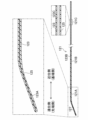
- the device 3 has a support portion 31 that supports the sample S and a base 34.
- the sample S was fixed to the support portion 31 so that the tip portion of the sample S protruded from the support portion 31 toward the base 34 by about 20 mm. 5, the supporting portion 31 is moved toward the base 34, and the tip of the sample S is placed on the base 34 on a 1 mm-thick silicone rubber sheet 33 (having a hardness of 50). °).
- the load [gf] required to push the tip of the sample S 1 mm after contact with the surface of the silicone rubber sheet 33 was measured.
- Each sample of Experimental Examples 1 to 4 was measured three times.
- the load of the sample of Experimental Example 1 is smaller than the load of the samples of Experimental Examples 2 to 4, and the tip of the sample of Experimental Example 1 is the tip of the sample of Experimental Examples 2 to 4. was found to be more flexible than
- the stylets of Experimental Examples 2 and 3 are used in a state in which the tip does not protrude from the distal end of the catheter body. Therefore, the catheter is relatively rigid in order to have stiffness, and it is found that the flexibility is greatly inferior to that of the guide wire of Experimental Example 4. That is, the stylets of Experimental Examples 2 and 3 have the risk of perforation of the blood vessel, and cannot be used with the tip protruding from the distal end of the catheter body.
- the distal end of the stylet of Experimental Example 1 is sufficiently soft even compared to the distal end of the guidewire of Experimental Example 4. Therefore, even if the tip of the stylet protrudes from the distal end of the catheter body, the risk of perforation of the blood vessel by the tip of the stylet is effectively reduced.
- the catheter of the present disclosure is extremely useful in the medical field.
Abstract
A catheter 1 is a periphery insertion type central venous catheter, said catheter 1 comprising a catheter main body 11 and a stylet 12 that is inserted through the catheter main body 11, wherein the stylet 12 has a projection part 122 that has a tip end portion 121A which is more flexible than an intermediate portion 121B and a base end portion 121C and that projects from an opening 112A of a tip 112 of the catheter main body 11.
Description
本開示は、末梢静脈挿入式中心静脈用カテーテルに関する。
The present disclosure relates to a peripherally inserted central venous catheter.
従来から、血管等の体内管状組織に対して検査や治療等を行うための医療器具の一種としてカテーテルが用いられている。例えば、点滴等の際に、上腕等の末梢静脈から挿入して先端を心臓近くの中心静脈に位置させる末梢静脈挿入式中心静脈用カテーテル(PICC)が用いられる。PICCは、心臓近くの太い血管に薬剤を送り込めるため、薬剤による静脈炎等が生じにくい。一方、PICCを留置する際には、上腕の静脈から挿入して上大静脈に到達するまでの長い距離を押し進める必要がある。カテーテルを押し進めるためには、コシが必要であるが、カテーテル自体を硬くすると、血管へのダメージが大きくなるという問題がある。従って、カテーテル自体は比較的柔らかくしガイドワイヤ又はスタイレットを併用することにより、挿入及び押し進めるために必要なコシをもたせることが行われている。
Conventionally, catheters have been used as a type of medical device for examining and treating body tubular tissues such as blood vessels. For example, a peripheral vein insertion type central venous catheter (PICC) is used, which is inserted from a peripheral vein such as an upper arm and positioned at a central vein near the heart at the time of infusion or the like. Since PICC can deliver drugs to thick blood vessels near the heart, phlebitis and the like due to drugs are less likely to occur. On the other hand, when placing a PICC, it is necessary to insert it from a vein in the upper arm and push it over a long distance to reach the superior vena cava. Although stiffness is necessary to push the catheter forward, there is a problem that if the catheter itself is hardened, the damage to the blood vessel increases. Therefore, the catheter itself is made relatively soft and combined with a guide wire or stylet to provide the necessary stiffness for insertion and pushing.
例えばガイドワイヤを使用してカテーテルを挿入する方法として、先にガイドワイヤを血管内に留置し、挿入されたガイドワイヤにカテーテルを沿わせて血管内に挿入するセルジンガー法が知られている。しかしながら、末梢血管から挿入するPICCでは、カイドワイヤの全長は約150cmにも及び、カテーテルの全長も約60cmに及ぶ。このため、PICCの場合、セルジンガー法の手技は煩雑である。
For example, as a method of inserting a catheter using a guidewire, the Seldinger method is known, in which the guidewire is first indwelled in the blood vessel, and the catheter is inserted into the blood vessel along the inserted guidewire. However, in a PICC inserted from a peripheral blood vessel, the total length of the guide wire is as high as about 150 cm, and the total length of the catheter is also as high as about 60 cm. Therefore, in the case of PICC, the technique of the Seldinger method is complicated.
また、カテーテル内に挿入するスタイレットは、ガイドワイヤと比較して柔軟性が劣るため、スタイレットの先端部が血管の内壁を傷付けないように、該先端部をカテーテルから突出させないで使用する。しかしながら、スタイレットの先端部がカテーテルから突出していない場合には、カテーテルの先端部が血管の内壁に直接接触する。樹脂製のカテーテルは柔らかいものではあるが、先端にエッジが生じている場合には、接触により血管の内壁を傷つけるおそれがある。特に、先端部を切断してカテーテルの長さを調節する場合があり、この場合には先端に鋭利なエッジが生じるので、穿孔のリスクがある。
In addition, since the stylet inserted into the catheter is less flexible than the guidewire, the tip of the stylet should not protrude from the catheter so as not to damage the inner wall of the blood vessel. However, if the stylet tip does not protrude from the catheter, the catheter tip directly contacts the inner wall of the vessel. A catheter made of resin is soft, but if it has an edge at its tip, it may damage the inner wall of the blood vessel by contact. In particular, the length of the catheter may be adjusted by severing the tip, which presents a sharp edge at the tip and thus risks perforation.
特許文献1には、合成樹脂からなる折れ曲がり部を先端に有する中心静脈カテーテル用スタイレットが開示されている。特許文献1のスタイレットは、折れ曲がり部が金属よりも柔らかい合成樹脂で形成されているため、折れ曲がり部を含む先端部がカテーテルの先端部から突出しても血管の内壁を傷付けることを防止できると期待される。
Patent Document 1 discloses a stylet for a central venous catheter having a bending portion made of synthetic resin at its tip. In the stylet of Patent Document 1, the bent portion is made of a synthetic resin that is softer than metal, so it is expected that even if the distal end including the bent portion protrudes from the distal end of the catheter, the inner wall of the blood vessel can be prevented from being damaged. be done.
しかしながら、特許文献1のスタイレットは、最長でも約20cm程度である。よって、太い静脈に挿入する中枢挿入式中心静脈用カテーテルの場合には、特許文献1に記載のスタイレットを用いることができる。しかしながら、全長が以上のカテーテルよりも長く、細い末梢血管から挿入するPICCにおいては、このようなスタイレットを用いることは困難である。
However, the stylet of Patent Document 1 has a maximum length of about 20 cm. Therefore, in the case of a centrally inserted central venous catheter to be inserted into a large vein, the stylet described in Patent Document 1 can be used. However, it is difficult to use such a stylet in PICC, which is longer than the above-mentioned catheter and is inserted from a narrow peripheral blood vessel.
そこで本開示は、挿入に必要なコシを有するとともに血管内壁の穿孔リスクを抑制できるPICCを実現できるようにする。
Therefore, the present disclosure makes it possible to realize a PICC that has the necessary stiffness for insertion and can suppress the risk of perforation of the inner wall of the blood vessel.
上記の課題を解決するために、ここに開示するカテーテルの一態様は、末梢静脈挿入式中心静脈用のカテーテルであって、カテーテル本体と、前記カテーテル本体に挿通されたスタイレットと、を備え、前記スタイレットは、該スタイレットの他の部分よりも柔軟な先端部を有するとともに、前記カテーテル本体の遠位端から突出する突出部を有する。
In order to solve the above problems, one aspect of the catheter disclosed herein is a peripheral vein insertion type central vein catheter, comprising a catheter body and a stylet inserted through the catheter body, The stylet has a tip that is softer than the rest of the stylet and has a projection projecting from the distal end of the catheter body.
本開示に係るカテーテルの一態様は、カテーテル本体にスタイレットが挿入されて血管内に挿入される。従って、ガイドワイヤを先に血管に挿入した後で、カテーテル本体を挿入する煩雑な操作を省くことができるとともに、カテーテルの挿入時に必要なコシと折れにくさを確保できる。また、スタイレットの突出部がカテーテル本体の遠位端から突出しているので、カテーテルの挿入時に当該突出部がガイドとなり、血管の穿孔リスクを低減できる。さらに、スタイレットの先端部は、該スタイレットの他の部分よりも柔軟であるので、スタイレットの先端部が血管を傷つけるリスクも低減できる。
In one aspect of the catheter according to the present disclosure, the stylet is inserted into the catheter body and inserted into the blood vessel. Therefore, it is possible to omit the troublesome operation of inserting the catheter main body after inserting the guide wire into the blood vessel first, and to ensure the necessary stiffness and resistance to breakage when inserting the catheter. In addition, since the protruding portion of the stylet protrudes from the distal end of the catheter body, the protruding portion serves as a guide during insertion of the catheter, reducing the risk of perforation of the blood vessel. Furthermore, since the tip of the stylet is more flexible than the rest of the stylet, the risk of damaging the blood vessel with the tip of the stylet can be reduced.
前記スタイレットは、金属ワイヤからなる芯材を備え、前記芯材の先端部の径が該芯材の他の部分の径よりも小さいことが好ましい。
It is preferable that the stylet has a core made of a metal wire, and the diameter of the tip of the core is smaller than the diameter of the rest of the core.
本構成によれば、芯材の径を調整することにより、スタイレットの先端部の柔軟性を調整できるから、必要なコシと折れにくさを十分に確保しつつ、血管の穿孔リスクを効果的に低減できるカテーテルを、簡便な方法でもたらすことができる。
According to this configuration, since the flexibility of the tip of the stylet can be adjusted by adjusting the diameter of the core material, the risk of perforation of the blood vessel can be effectively reduced while sufficiently ensuring necessary stiffness and resistance to breakage. can be provided in a convenient manner.
前記スタイレットの先端部は、コイル形状を有してもよい。
The tip of the stylet may have a coil shape.
本構成によれば、血管の穿孔リスクを効果的に低減できる。
According to this configuration, the risk of blood vessel perforation can be effectively reduced.
前記スタイレットは、前記芯材を被覆する樹脂層を備え、前記スタイレットの外径は、前記芯材の全長に亘って略一定であることが好ましい。
It is preferable that the stylet includes a resin layer covering the core material, and that the outer diameter of the stylet is substantially constant over the entire length of the core material.
本構成では、芯材の先端部の径は該芯材の他の部分の径よりも小さいことから、スタイレットの先端部では該スタイレットの他の部分よりも樹脂層が厚く、これにより、スタイレットの外径は芯材の全長に亘って略一定となっている。本構成によれば、スタイレットの先端部における十分な柔軟性を確保するとともに、スタイレット全体の十分な強度を確保できる。なお、本明細書において、「外径が略一定」とは、外径と最大外径との差が最大外径の20%以内であることをいう。
In this configuration, since the diameter of the tip portion of the core material is smaller than the diameter of the other portion of the core material, the resin layer is thicker at the tip portion of the stylet than at the other portion of the stylet. The outer diameter of the stylet is substantially constant over the entire length of the core. According to this configuration, it is possible to ensure sufficient flexibility at the distal end of the stylet and sufficient strength of the entire stylet. In this specification, the term "substantially constant outer diameter" means that the difference between the outer diameter and the maximum outer diameter is within 20% of the maximum outer diameter.
前記スタイレットの突出部の長さは、10mm以上50mm以下であることが好ましい。
The length of the projecting portion of the stylet is preferably 10 mm or more and 50 mm or less.
スタイレットの突出部の長さが下限値未満では、スタイレットが少し曲がるとカテーテル本体の先端部が血管内壁に接触する可能性が生じる。スタイレットの突出部の長さが上限値を超えると、カテーテルを血管内に留置するときに、カテーテル本体の先端部が例えば心臓の内部へ意図せずに入ってしまう等、配置すべき適切な位置に配置されない可能性が生じる。スタイレットの突出部の長さを上記範囲とすることにより、血管の穿孔リスクを効果的に低減できるとともに、取扱い性に優れたカテーテルをもたらすことができる。
If the length of the protruding portion of the stylet is less than the lower limit, the tip of the catheter body may come into contact with the inner wall of the blood vessel if the stylet bends slightly. If the length of the protruding portion of the stylet exceeds the upper limit, the tip of the catheter body may inadvertently enter, for example, the heart when the catheter is placed in a blood vessel. There is a possibility that it will not be placed in position. By setting the length of the projecting portion of the stylet within the above range, the risk of perforation of the blood vessel can be effectively reduced, and a catheter with excellent handleability can be provided.
前記カテーテル本体の長さは、40cm以上であることが好ましい。
The length of the catheter body is preferably 40 cm or longer.
本構成によれば、末梢静脈挿入式中心静脈用のカテーテルとして好適に使用することができる。
According to this configuration, it can be suitably used as a peripheral vein insertion type central vein catheter.
以上述べたように、本開示によると、ガイドワイヤを先に血管に挿入した後で、カテーテル本体を挿入する煩雑な操作を省くことができるとともに、カテーテルの挿入時に必要なコシと折れにくさを確保できる。また、カテーテルの挿入時にスタイレットの突出部がガイドとなり、血管の穿孔リスクを低減できる。さらに、スタイレットの先端部は、該スタイレットの他の部分よりも柔軟であるので、スタイレットの先端部が血管を傷つけるリスクも低減できる。
As described above, according to the present disclosure, it is possible to omit the complicated operation of inserting the catheter main body after inserting the guide wire into the blood vessel first, and to provide the necessary stiffness and resistance to breakage when inserting the catheter. can be secured. In addition, the projecting portion of the stylet serves as a guide when inserting the catheter, and the risk of perforation of the blood vessel can be reduced. Furthermore, since the tip of the stylet is more flexible than the rest of the stylet, the risk of damaging the blood vessel with the tip of the stylet can be reduced.
以下、本開示の実施形態を図面に基づいて詳細に説明する。以下の好ましい実施形態の説明は、本質的に例示に過ぎず、本開示、その適用物或いはその用途を制限することを意図するものでは全くない。
Hereinafter, embodiments of the present disclosure will be described in detail based on the drawings. The following description of preferred embodiments is merely exemplary in nature and is in no way intended to limit the disclosure, its applicability or its uses.
<カテーテル>
図1は、本開示の一実施形態に係る末梢静脈挿入式中心静脈用のカテーテル1の全体図である。図2は、図1のA-A線における断面図である。 <Catheter>
FIG. 1 is a general view of a peripherally inserted centralvenous catheter 1 according to an embodiment of the present disclosure. FIG. 2 is a cross-sectional view taken along line AA of FIG.
図1は、本開示の一実施形態に係る末梢静脈挿入式中心静脈用のカテーテル1の全体図である。図2は、図1のA-A線における断面図である。 <Catheter>
FIG. 1 is a general view of a peripherally inserted central
カテーテル1は、末梢静脈より導入して上大静脈に挿入及び留置し、中心静脈への薬液注入、血液の採取、静脈圧測定等を行うための医療器具である。なお、本明細書において、カテーテル1の血管挿入側を遠位側又は先端側、術者が操作する手元側を近位側又は基端側と称する。
The catheter 1 is a medical device that is introduced from a peripheral vein, inserted into the superior vena cava, and left in place to inject drug solutions into the central vein, collect blood, measure venous pressure, and the like. In this specification, the blood vessel insertion side of the catheter 1 is referred to as the distal side or tip side, and the hand side operated by the operator is referred to as the proximal side or base end side.
図1及び図2に示すように、カテーテル1は、カテーテル本体11と、カテーテル本体11に挿通されたスタイレット12と、を備える。
As shown in FIGS. 1 and 2, the catheter 1 includes a catheter body 11 and a stylet 12 inserted through the catheter body 11.
≪カテーテル本体≫
カテーテル本体11は、ダブルルーメン構造を有するチューブ状の部材である。なお、カテーテル本体11は、ダブルルーメン構造に限られるものではなく、シングルルーメン構造、トリプルルーメン構造等であってもよい。 ≪Catheter body≫
Thecatheter body 11 is a tubular member having a double lumen structure. Note that the catheter body 11 is not limited to the double lumen structure, and may have a single lumen structure, a triple lumen structure, or the like.
カテーテル本体11は、ダブルルーメン構造を有するチューブ状の部材である。なお、カテーテル本体11は、ダブルルーメン構造に限られるものではなく、シングルルーメン構造、トリプルルーメン構造等であってもよい。 ≪Catheter body≫
The
カテーテル本体11の長さは、ヒトの四肢や冠状動脈等のカテーテル挿入部から患部までの長さを考慮して適宜設定され得るが、カテーテル1がPICCであることから、少なくとも末梢静脈のカテーテル挿入部から上大静脈の患部に至る長さを有している。具体的には、カテーテル本体11の長さは、好ましくは全長40cm以上である。
The length of the catheter body 11 can be appropriately set in consideration of the length from the catheter insertion site such as a human extremity or coronary artery to the affected area. It has a length from the apex to the affected part of the superior vena cava. Specifically, the length of the catheter body 11 is preferably 40 cm or longer.
図1に示すように、カテーテル本体11は、シャフト111と、先端チップ112と、Y管部113と、第1枝管114及び第2枝管115と、第1ポート114A及び第2ポート115Aと、第1クランプ114B及び第2クランプ115Bと、を有する。
As shown in FIG. 1, the catheter body 11 includes a shaft 111, a distal tip 112, a Y tube portion 113, a first branch tube 114 and a second branch tube 115, a first port 114A and a second port 115A. , a first clamp 114B and a second clamp 115B.
-シャフト-
シャフト111は、可撓性を有する長尺のチューブであり、図2に示すように、互いに独立した通路である第1ルーメン111A及び第2ルーメン111Bを備える。 -shaft-
Theshaft 111 is a flexible, elongated tube, and as shown in FIG. 2, has a first lumen 111A and a second lumen 111B that are independent passages.
シャフト111は、可撓性を有する長尺のチューブであり、図2に示すように、互いに独立した通路である第1ルーメン111A及び第2ルーメン111Bを備える。 -shaft-
The
シャフト111の遠位端側には、サイドホール型の開口部111Cが設けられている。第2ルーメン111Bは、当該開口部111Cにおいて開口している。
A side-hole type opening 111C is provided on the distal end side of the shaft 111 . The second lumen 111B opens at the opening 111C.
シャフト111の具体的構造は特に限定されるものではない。シャフト111は、例えばポリウレタン、ポリエチレン、ポリエステル、ポリプロピレン、ポリエーテルブロックアミド、ポリアミド、ポリテトラフルオロエチレン、ポリフッ化ビニリデン等の1種又は2種以上の生体適合性を有する樹脂材で形成され得る。シャフト111は、上記樹脂材の単一層で形成されてもよいし、複数層で形成されてもよい。また、シャフト111は、上記樹脂材の複数層で形成され、層間にステンレス鋼やNi-Ti合金等の金属や樹脂からなる繊維や線等によるメッシュ状の筒状編組体が埋設状態で設けられた積層構造等であってもよい。さらに、シャフト111を長手方向に複数に分割し、複数の部位毎に異なる樹脂材を使用して形成してもよい。この場合、細く蛇行する血管への挿通性を向上させる観点から、シャフト111の遠位端側の部位を近位端側の部位よりも柔軟な材質を用いて形成してもよい。
The specific structure of the shaft 111 is not particularly limited. The shaft 111 may be made of one or more biocompatible resin materials such as polyurethane, polyethylene, polyester, polypropylene, polyether block amide, polyamide, polytetrafluoroethylene, and polyvinylidene fluoride. The shaft 111 may be formed of a single layer of the resin material, or may be formed of multiple layers. The shaft 111 is formed of a plurality of layers of the resin material, and a mesh-like cylindrical braided body made of metal such as stainless steel or Ni—Ti alloy or resin is embedded between the layers. A laminated structure or the like may also be used. Furthermore, the shaft 111 may be divided into a plurality of sections in the longitudinal direction, and different resin materials may be used for each of the plurality of sections. In this case, from the viewpoint of improving the ability to pass through thin, meandering blood vessels, the distal end side portion of the shaft 111 may be formed using a material that is more flexible than the proximal end side portion.
また、例えばシャフト111の成形樹脂層に対して酸化ビスマスや硫酸ビスマス、次炭酸ビスマス、タングステン等の造影剤を配合してもよいし、シャフト111の外周面又は層間にステンレス鋼や金、白金、イリジウム等からなる造影マーカ等が設けられてもよい。これにより、術中でのX線による視認性を確保できる。
Further, for example, a contrast agent such as bismuth oxide, bismuth sulfate, bismuth subcarbonate, or tungsten may be added to the molding resin layer of the shaft 111, or stainless steel, gold, platinum, or the like may be added to the outer peripheral surface of the shaft 111 or between layers. Contrast markers or the like made of iridium or the like may be provided. As a result, it is possible to secure visibility with X-rays during surgery.
-先端チップ-
先端チップ112は、シャフト111の遠位端に設けられたチューブ状の部材であり、カテーテル本体11の先端部を構成している。 - tip -
Thedistal tip 112 is a tubular member provided at the distal end of the shaft 111 and constitutes the distal end of the catheter body 11 .
先端チップ112は、シャフト111の遠位端に設けられたチューブ状の部材であり、カテーテル本体11の先端部を構成している。 - tip -
The
先端チップ112の近位端は、シャフト111の遠位端と略同一の外内径寸法を有しており、シャフト111の遠位端から一体的につながっている。そして、先端チップ112の内腔の近位端は、第1ルーメン111Aと通じており、遠位端はエンドホール型の開口部112A(カテーテル本体の遠位端)を形成している。
The proximal end of the distal tip 112 has substantially the same outer and inner diameter dimensions as the distal end of the shaft 111 and is integrally connected with the distal end of the shaft 111 . The proximal end of the lumen of the distal tip 112 communicates with the first lumen 111A, and the distal end forms an endhole-shaped opening 112A (the distal end of the catheter main body).
先端チップ112は、シャフト111と一体成形されていてもよいし、適切な樹脂材料で別体形成されて接着や溶着等でシャフト111の遠位端に固着されていてもよい。先端チップ112は、シャフト111と同様の材料により、単一層又は複数層で形成され得る。なお、先端チップ112は、血管の穿孔リスクを低減させる観点から、シャフト111より柔軟な材質からなることが好ましい。
The distal tip 112 may be integrally molded with the shaft 111, or may be formed separately from an appropriate resin material and fixed to the distal end of the shaft 111 by adhesion, welding, or the like. Distal tip 112 may be formed of a single layer or multiple layers of the same material as shaft 111 . Note that the distal tip 112 is preferably made of a material that is more flexible than the shaft 111 from the viewpoint of reducing the risk of blood vessel perforation.
また、先端チップ112においても、シャフト111と同様に、成形材料に造影剤が配合されてもよいし、外周面又は層間に造影マーカ等が設けられてもよい。これにより、カテーテル本体11の先端部がX線透視下で視認可能となる。
Also, in the distal tip 112, similarly to the shaft 111, a contrast agent may be blended in the molding material, or a contrast marker or the like may be provided on the outer peripheral surface or between the layers. This allows the distal end of the catheter body 11 to be visually recognized under X-ray fluoroscopy.
-Y管部-
Y管部113は、シャフト111の近位端に設けられ、第1ルーメン111A及び第2ルーメン111Bの各々と連続する独立した2つの内腔を有するチューブ状の部材である。Y管部113は、ポリウレタン等の樹脂成形体であり、例えばカテーテル1の挿抜等の操作において持ち手となり得る。 -Y tube part-
TheY tube portion 113 is provided at the proximal end of the shaft 111 and is a tubular member having two independent lumens that are continuous with each of the first lumen 111A and the second lumen 111B. The Y tube part 113 is a resin molded body such as polyurethane, and can serve as a handle for inserting and removing the catheter 1, for example.
Y管部113は、シャフト111の近位端に設けられ、第1ルーメン111A及び第2ルーメン111Bの各々と連続する独立した2つの内腔を有するチューブ状の部材である。Y管部113は、ポリウレタン等の樹脂成形体であり、例えばカテーテル1の挿抜等の操作において持ち手となり得る。 -Y tube part-
The
-枝管、ポート及びクランプ-
第1枝管114及び第2枝管115は、Y管部113の近位端に接続されたチューブ状の部材である。 -Branches, Ports and Clamps-
Thefirst branch tube 114 and the second branch tube 115 are tubular members connected to the proximal end of the Y tube portion 113 .
第1枝管114及び第2枝管115は、Y管部113の近位端に接続されたチューブ状の部材である。 -Branches, Ports and Clamps-
The
第1枝管114の内腔は、第1ルーメン111Aに接続されたY管部113の内腔と通じている。第1枝管114の近位端には、第1ポート114Aが設けられている。また、第1枝管114におけるY管部113と第1ポート114Aとの間には、第1クランプ114Bが設けられている。
The lumen of the first branch tube 114 communicates with the lumen of the Y tube portion 113 connected to the first lumen 111A. A first port 114A is provided at the proximal end of the first branch tube 114 . A first clamp 114B is provided between the Y tube portion 113 and the first port 114A of the first branch tube 114 .
第2枝管115の内腔は、第2ルーメン111Bに接続されたY管部113の内腔と通じている。第2枝管115の近位端には、第2ポート115Aが設けられている。また、第2枝管115におけるY管部113と第2ポート115Aとの間には、第2クランプ115Bが設けられている。
The lumen of the second branch tube 115 communicates with the lumen of the Y tube portion 113 connected to the second lumen 111B. The proximal end of the second branch tube 115 is provided with a second port 115A. A second clamp 115B is provided between the Y tube portion 113 of the second branch tube 115 and the second port 115A.
-遠位ルーメン及び近位ルーメン-
シャフト111の第1ルーメン111A、先端チップ112の内腔、第1ルーメン111Aに接続されたY管部113の内腔、並びに、第1枝管114及び第1ポート114Aの内腔により、遠位ルーメンが構成されている。 -Distal Lumen and Proximal Lumen-
First lumen 111A of shaft 111, the lumen of distal tip 112, the lumen of Y tube 113 connected to first lumen 111A, and the lumens of first branch tube 114 and first port 114A provide distal lumens are configured.
シャフト111の第1ルーメン111A、先端チップ112の内腔、第1ルーメン111Aに接続されたY管部113の内腔、並びに、第1枝管114及び第1ポート114Aの内腔により、遠位ルーメンが構成されている。 -Distal Lumen and Proximal Lumen-
また、シャフト111の第2ルーメン111B、第2ルーメン111Bに接続されたY管部113の内腔、並びに、第2枝管115及び第2ポート115Aの内腔により、近位ルーメンが構成されている。
A proximal lumen is formed by the second lumen 111B of the shaft 111, the lumen of the Y tube portion 113 connected to the second lumen 111B, and the lumens of the second branch tube 115 and the second port 115A. there is
カテーテル1は、オーバーザワイヤ型であり、スタイレット12は、第1ポート114Aを通じて遠位ルーメンに挿通される。すなわち、遠位ルーメンの内径は、スタイレット12が挿入可能な径に設定されている。なお、遠位ルーメンを構成する各部材の内周面にPTFE(ポリテトラフルオロエチレン)等の低摩擦樹脂を塗布してもよい。これにより、内周面の摩擦係数を低減できるから、スタイレット12の挿通性が向上する。
The catheter 1 is of an over-the-wire type, and the stylet 12 is passed through the distal lumen through the first port 114A. That is, the inner diameter of the distal lumen is set to a diameter that allows the stylet 12 to be inserted. In addition, a low-friction resin such as PTFE (polytetrafluoroethylene) may be applied to the inner peripheral surface of each member constituting the distal lumen. As a result, the coefficient of friction of the inner peripheral surface can be reduced, so that the insertability of the stylet 12 is improved.
また、近位ルーメンは、造影剤又は生理食塩水や空気等の流体が流通可能な空間である。
In addition, the proximal lumen is a space through which fluids such as a contrast medium, physiological saline, and air can flow.
なお、カテーテル1は、オーバーザワイヤ型に限られるものではなく、ラピッドエクスチェンジ型等の他の公知の構造であってもよい。
Note that the catheter 1 is not limited to the over-the-wire type, and may have other known structures such as a rapid exchange type.
≪スタイレット≫
カテーテル1は、カテーテル本体11の遠位ルーメンにスタイレット12が挿入され、後述する突出部122が開口部112Aから突出した状態で血管内に挿入される。すなわち、スタイレット12は、カテーテル本体11の少なくとも遠位ルーメンよりも長く構成されている。 ≪Stylet≫
Thecatheter 1 is inserted into a blood vessel with the stylet 12 inserted into the distal lumen of the catheter main body 11 and a protruding portion 122 described later protruding from the opening 112A. That is, the stylet 12 is longer than at least the distal lumen of the catheter body 11 .
カテーテル1は、カテーテル本体11の遠位ルーメンにスタイレット12が挿入され、後述する突出部122が開口部112Aから突出した状態で血管内に挿入される。すなわち、スタイレット12は、カテーテル本体11の少なくとも遠位ルーメンよりも長く構成されている。 ≪Stylet≫
The
本構成によれば、セルジンガー法のように、ガイドワイヤを先に血管に挿入した後でカテーテル本体を挿入するような煩雑な操作を省くことができるとともに、カテーテル1の挿入時に必要なコシと折れにくさを確保できる。
According to this configuration, it is possible to omit complicated operations such as inserting the guide wire into the blood vessel first and then inserting the catheter main body as in the Seldinger method, and the stiffness and stiffness required when inserting the catheter 1 can be omitted. It is possible to ensure the resistance to breakage.
図1及び図3に示すように、スタイレット12は、スタイレット本体121と、保護部材129と、を有する。
As shown in FIGS. 1 and 3, the stylet 12 has a stylet body 121 and a protective member 129. As shown in FIGS.
-保護部材-
保護部材129は、スタイレット本体121の近位端に設けられており、スタイレット12の基端部を構成している。保護部材129は、術者が把持してスタイレット12を操作するための、例えば円柱状、板状等の部材である。保護部材129は、例えばポリプロピレン、ポリカーボネート、塩化ビニル等からなる。 -Protective material-
Theprotective member 129 is provided at the proximal end of the stylet body 121 and constitutes the proximal end of the stylet 12 . The protective member 129 is, for example, a columnar or plate-like member that is gripped by the operator to operate the stylet 12 . The protective member 129 is made of, for example, polypropylene, polycarbonate, vinyl chloride, or the like.
保護部材129は、スタイレット本体121の近位端に設けられており、スタイレット12の基端部を構成している。保護部材129は、術者が把持してスタイレット12を操作するための、例えば円柱状、板状等の部材である。保護部材129は、例えばポリプロピレン、ポリカーボネート、塩化ビニル等からなる。 -Protective material-
The
-スタイレット本体-
スタイレット本体121は、シャフト111よりも剛性の大きい線材であり、ある程度の弾性をもって元形状に保持されるとともに、変形後にも元形状へ復元されるようになっている。これにより、カテーテル1の挿入時に必要なコシと折れにくさを確保できる。 -Stylet Body-
The styletmain body 121 is a wire material having a higher rigidity than the shaft 111, and has a certain degree of elasticity so that it can be held in its original shape and can be restored to its original shape even after being deformed. As a result, the necessary stiffness and resistance to breakage when inserting the catheter 1 can be ensured.
スタイレット本体121は、シャフト111よりも剛性の大きい線材であり、ある程度の弾性をもって元形状に保持されるとともに、変形後にも元形状へ復元されるようになっている。これにより、カテーテル1の挿入時に必要なコシと折れにくさを確保できる。 -Stylet Body-
The stylet
スタイレット本体121の外径寸法は、遠位ルーメンの内径寸法より十分小さく設定されている。スタイレット本体121の長さは、スタイレット12の全長がカテーテル本体11の遠位ルーメンよりも長くなるように、構成されている。
The outer diameter dimension of the stylet body 121 is set sufficiently smaller than the inner diameter dimension of the distal lumen. The length of stylet body 121 is configured such that the overall length of stylet 12 is longer than the distal lumen of catheter body 11 .
図4に示すように、スタイレット本体121は、芯材123と、該芯材123を被覆する樹脂層125と、を備える。芯材123は、例えばステンレス鋼やNi-Ti合金等の金属ワイヤからなる。樹脂層125は、例えばPTFE、PFA(テトラフルオロエチレン-パーフルオロアルキルビニルエーテル共重合体)、ETFE(エチレン-テトラフルオロエチレン共重合体)等のフッ素系樹脂、ポリウレタン、親水性コーティング等よりなる。樹脂層125は、スタイレット12を遠位ルーメンに挿通させるときの滑りやすさを確保するために設けられるが、設けられなくてもよい。なお、芯材123は、造影性を有する金属で形成されてもよい。また、芯材123と樹脂層125との間に造影マーカを設けてもよい。これにより、スタイレット12がX線透視下で視認可能となる。
As shown in FIG. 4 , the stylet body 121 includes a core material 123 and a resin layer 125 covering the core material 123 . The core material 123 is made of metal wire such as stainless steel or Ni--Ti alloy. The resin layer 125 is made of fluorine resin such as PTFE, PFA (tetrafluoroethylene-perfluoroalkyl vinyl ether copolymer), ETFE (ethylene-tetrafluoroethylene copolymer), polyurethane, hydrophilic coating, or the like. The resin layer 125 is provided to ensure slipperiness when the stylet 12 is passed through the distal lumen, but may not be provided. Note that the core material 123 may be formed of a metal having contrast enhancement properties. Also, a contrast marker may be provided between the core material 123 and the resin layer 125 . This allows the stylet 12 to be visible under X-ray fluoroscopy.
また、図4に示すように、芯材123の先端が露出しないように、芯材123の先端及び基端も樹脂層125により被覆されていることが好ましい。なお、芯材123の先端の遠位側及び基端の近位側に位置する樹脂層125のみの部分の長さは、芯材123の後述する先端部123Aを被覆する樹脂層125の厚さの2倍以下、芯材123の後述する基端部123Cを被覆する樹脂層125の厚さ以上であることが好ましい。本構成によれば、スタイレット本体121のほぼ全長に亘って芯材123が存在しているから、スタイレット本体121の先端部121Aが樹脂のみで形成されている場合に比べて、カテーテル1の挿入性が向上する。また、芯材123が造影性を有する金属で形成されている場合は、X線透視下におけるスタイレット12の先端位置の視認性が向上する。なお、樹脂層125のみの部分、すなわちスタイレット本体121の先端及び基端は、角部をなくすように研磨等で面取りされて丸められていることが望ましい。
In addition, as shown in FIG. 4, it is preferable that the tip and base ends of the core material 123 are also covered with the resin layer 125 so that the tip of the core material 123 is not exposed. The length of only the resin layer 125 located on the distal side of the distal end of the core material 123 and the proximal side of the proximal end of the core material 123 is the thickness of the resin layer 125 covering the distal end portion 123A of the core material 123, which will be described later. , and is preferably equal to or greater than the thickness of the resin layer 125 covering the base end portion 123C of the core member 123, which will be described later. According to this configuration, since the core material 123 exists over almost the entire length of the stylet body 121, the catheter 1 is more flexible than when the distal end portion 121A of the stylet body 121 is made of only resin. Improves insertability. In addition, when the core material 123 is made of a metal having contrast properties, the visibility of the tip position of the stylet 12 under X-ray fluoroscopy is improved. It should be noted that the portion where only the resin layer 125 is present, that is, the distal end and the proximal end of the stylet body 121 is desirably chamfered and rounded by polishing or the like so as to eliminate corners.
図1に示すように、スタイレット本体121は、スタイレット12を遠位ルーメンに挿通させたときに、先端チップ112の開口部112Aから遠位側に突出する突出部122を備える。これにより、カテーテル1を血管内に挿入したときに、当該突出部122がガイドとなり、カテーテル本体11の先端チップ112による血管の穿孔リスクを低減できる。
As shown in FIG. 1, the stylet body 121 has a projecting portion 122 that projects distally from the opening 112A of the distal tip 112 when the stylet 12 is inserted through the distal lumen. As a result, when the catheter 1 is inserted into a blood vessel, the projecting portion 122 serves as a guide, and the risk of perforation of the blood vessel by the distal tip 112 of the catheter main body 11 can be reduced.
なお、突出部122の長さは、10mm以上50mm以下であることが好ましい。
It should be noted that the length of the projecting portion 122 is preferably 10 mm or more and 50 mm or less.
突出部122の長さが下限値未満では、スタイレット12が少し曲がるとカテーテル本体11の先端チップ112の遠位端が血管に接触する可能性が生じる。突出部122の長さが上限値を超えると、カテーテル1を血管内に留置するときに、先端チップ112が適切な位置に配置されない可能性が生じる。突出部122の長さを上記範囲とすることにより、血管の穿孔リスクを効果的に低減できるとともに、取扱い性に優れたカテーテル1をもたらすことができる。
If the length of the projecting portion 122 is less than the lower limit, the distal end of the tip 112 of the catheter body 11 may come into contact with the blood vessel when the stylet 12 is slightly bent. If the length of the protruding portion 122 exceeds the upper limit, there is a possibility that the tip 112 will not be placed at an appropriate position when the catheter 1 is left in the blood vessel. By setting the length of the protruding portion 122 within the above range, the risk of perforation of the blood vessel can be effectively reduced, and the catheter 1 with excellent handleability can be provided.
また、図3及び図4に示すように、スタイレット本体121は、先端部121Aと、中間部121Bと、基端部121Cと、を備える。中間部121B及び基端部121Cは、スタイレット本体121における他の部分である。なお、先端部121Aの一部、すなわち遠位側の部分が突出部122を構成していてもよいし、先端部121Aの全部が突出部122を構成していてもよい。また、先端部121A及び中間部121Bの遠位側の部分が突出部122を構成していてもよい。
Further, as shown in FIGS. 3 and 4, the stylet body 121 includes a distal end portion 121A, an intermediate portion 121B, and a proximal end portion 121C. The intermediate portion 121B and the base end portion 121C are other portions of the stylet body 121 . A portion of the distal end portion 121A, that is, a portion on the distal side may constitute the projecting portion 122, or the entire distal end portion 121A may constitute the projecting portion 122. FIG. In addition, distal portions of the distal end portion 121A and the intermediate portion 121B may constitute the projecting portion 122 .
ここに、先端部121Aは、中間部121B及び基端部121Cよりも柔軟となるように形成されている。
Here, the distal end portion 121A is formed to be more flexible than the intermediate portion 121B and the proximal end portion 121C.
具体的には、芯材123の先端部123Aの径が該芯材123の他の部分、すなわち中間部123B及び基端部123Cの径よりも小さくなるように、好ましくは基端部123C、中間部123B、及び先端部123Aの径がこの順に漸減するように、構成されている。これにより、スタイレット本体121の先端部121Aは、中間部121B及び基端部121Cよりも柔軟になっている。これにより、カテーテル1を血管内に挿入したときに、先端部121Aが血管を傷つけるリスクを低減できる。
Specifically, the diameter of the distal end portion 123A of the core member 123 is preferably smaller than the diameters of the other portions of the core member 123, that is, the intermediate portion 123B and the proximal portion 123C. The diameters of the portion 123B and the tip portion 123A are configured to gradually decrease in this order. As a result, the distal end portion 121A of the stylet body 121 is more flexible than the intermediate portion 121B and the proximal end portion 121C. Thereby, when the catheter 1 is inserted into the blood vessel, the risk of the tip portion 121A damaging the blood vessel can be reduced.
また、芯材123の径を調整することにより、先端部121Aの柔軟性を調整できるから、カテーテル1の挿入時に必要なコシと折れにくさを十分に確保しつつ、血管の穿孔リスクを効果的に低減できる。
In addition, by adjusting the diameter of the core material 123, the flexibility of the distal end portion 121A can be adjusted. Therefore, the risk of perforation of the blood vessel can be effectively reduced while sufficiently ensuring the stiffness and resistance to breakage required when the catheter 1 is inserted. can be reduced to
スタイレット本体121の外径は、芯材123の全長に亘って略一定である。すなわち、芯材123の先端部123Aの径は中間部123B及び基端部123Cの径よりも小さいから、スタイレット本体121の先端部121Aでは中間部121B及び基端部121Cよりも樹脂層125が厚く、これにより、スタイレット本体121の外径は芯材123の全長に亘って略一定となっている。本構成によれば、スタイレット本体121の先端部121Aにおける十分な柔軟性を確保するとともに、スタイレット本体121全体の十分な強度を確保できる。
The outer diameter of the stylet body 121 is substantially constant over the entire length of the core material 123 . That is, since the diameter of the distal end portion 123A of the core material 123 is smaller than the diameters of the intermediate portion 123B and the proximal end portion 123C, the distal end portion 121A of the stylet body 121 has a larger resin layer 125 than the intermediate portion 121B and the proximal end portion 121C. As a result, the outer diameter of the stylet body 121 is substantially constant over the entire length of the core member 123 . According to this configuration, it is possible to ensure sufficient flexibility at the distal end portion 121A of the stylet body 121 and to ensure sufficient strength of the stylet body 121 as a whole.
なお、後述する先端荷重測定試験により測定された、スタイレット12の先端部121Aの荷重は、30gf以下であることが好ましい。また、当該荷重は、20gf以下であることがより好ましく、2gf以下であることが特に好ましい。先端部121Aの荷重を当該範囲とすることにより、血管の穿孔リスクを効果的に低減できる。また、スタイレット12の先端部121Aの荷重の下限値は、特に限定する意図ではないが、例えば0.1gf以上とすることができる。
It should be noted that the load on the distal end portion 121A of the stylet 12 measured by a distal end load measurement test described later is preferably 30 gf or less. Moreover, the load is more preferably 20 gf or less, and particularly preferably 2 gf or less. By setting the load of the distal end portion 121A within this range, the perforation risk of the blood vessel can be effectively reduced. Also, the lower limit of the load applied to the distal end portion 121A of the stylet 12 is not intended to be particularly limited, but can be set to, for example, 0.1 gf or more.
先端部121Aの遠位端側には、屈曲部127が設けられている。すなわち、スタイレット12の先端形状はアングル型である。なお、スタイレット12は、アングル型に限られるものではなく、ストレート型、J型等の他の先端形状を有していてもよい。
A bent portion 127 is provided on the distal end side of the tip portion 121A. That is, the tip shape of the stylet 12 is an angle type. Note that the stylet 12 is not limited to the angle type, and may have other tip shapes such as a straight type and a J type.
屈曲部127の長さは例えば約10mmとすることができるが、特に限定されるものではない。また、屈曲部127は直線状に記載されているが、湾曲形状であってもよい。さらに、スタイレット本体121における屈曲部127よりも近位側の部分は直線状であってもよいし、曲線状であってもよい。なお、屈曲部127及び近位側の部分がいずれも直線状の場合、近位側の部分に平行な直線と屈曲部127とのなす角度は、特に限定されるものではないが、例えば10°~40°程度とすることができる。また、例えば、スタイレット本体121の全体が、大きな曲率半径をもって形成されていて且つ先端部121Aにだけ小さな曲率半径の屈曲部127が設けられていてもよい。さらに、先端部121Aにおいて、長さ方向で異なる位置に複数の屈曲部を設けてもよい。すなわち、スタイレット本体121の形状は何等限定されるものではなく、患者の血管形状等に応じて適宜に設計、変更され得る。
The length of the bent portion 127 can be, for example, about 10 mm, but is not particularly limited. In addition, although the bent portion 127 is described as linear, it may be curved. Further, the portion of stylet body 121 on the proximal side of bending portion 127 may be straight or curved. When both the bent portion 127 and the proximal portion are linear, the angle formed by the bent portion 127 and a straight line parallel to the proximal portion is not particularly limited, but is, for example, 10°. It can be about 40°. Alternatively, for example, the entire stylet body 121 may be formed with a large radius of curvature, and only the distal end portion 121A may be provided with a bent portion 127 having a small radius of curvature. Furthermore, a plurality of bent portions may be provided at different positions in the length direction of the distal end portion 121A. That is, the shape of the stylet main body 121 is not limited in any way, and can be designed and changed as appropriate according to the patient's blood vessel shape and the like.
また、芯材123を樹脂層125により被覆したスタイレットについて説明したが、スタイレットは、先端部が他の部分よりも柔軟であれば、このような構成に限られない。例えば、芯材とその回りに形成されたコイル線とを有する構成のスタイレットとすることができる。この場合、芯材の太さ、コイル線の太さ、コイル線の密度等を調整することにより、各部の柔軟性を調整することができる。また、スタイレットの全体をコイル形状とすることができるが、先端部を含む一部のみをコイル形状とすることもできる。また、樹脂層により被覆されたスタイレットの先端部をコイル形状とすることもできる。
Also, the stylet in which the core material 123 is covered with the resin layer 125 has been described, but the stylet is not limited to such a configuration as long as the tip portion is more flexible than the other portions. For example, the stylet may be configured to have a core and a coil wire formed therearound. In this case, the flexibility of each part can be adjusted by adjusting the thickness of the core material, the thickness of the coil wire, the density of the coil wire, and the like. Moreover, although the entire stylet can be coil-shaped, only a portion including the distal end portion can be coil-shaped. Also, the tip of the stylet covered with the resin layer may be coil-shaped.
-先端荷重測定試験-
図5に示す装置3を用いて先端荷重測定試験を行い、3種類のスタイレット及びガイドワイヤの先端部の柔軟性を評価した。結果を表1に示す。 -Tip load measurement test-
A tip load measurement test was performed using thedevice 3 shown in FIG. 5 to evaluate the flexibility of the tips of three types of stylets and guidewires. Table 1 shows the results.
図5に示す装置3を用いて先端荷重測定試験を行い、3種類のスタイレット及びガイドワイヤの先端部の柔軟性を評価した。結果を表1に示す。 -Tip load measurement test-
A tip load measurement test was performed using the

実験例1のサンプルは、本開示に係るカテーテル1のスタイレット12であり、芯材123は、Ni-Ti合金製ワイヤ、樹脂層125は、親水性コーティングである。中間部123Bの径は、基端部123Cから先端部123Aに向かって漸減するように構成されている。スタイレット本体121の径は、0.36~0.45mm程度である。スタイレット本体121の先端形状は後述するアングル型であり、約20°の傾斜が形成されている。
The sample of Experimental Example 1 is the stylet 12 of the catheter 1 according to the present disclosure, the core material 123 is a Ni-Ti alloy wire, and the resin layer 125 is a hydrophilic coating. The diameter of the intermediate portion 123B is configured to gradually decrease from the proximal end portion 123C toward the distal end portion 123A. The diameter of the stylet body 121 is approximately 0.36 to 0.45 mm. The tip shape of the stylet body 121 is an angle type, which will be described later, and is inclined at about 20°.
実験例2のサンプルは、市販のPICCキットに含まれるスタイレットであり、材質はステンレス、径は約0.5mmである。先端形状はストレート型である。なお、当該スタイレットは、カテーテル操作時、その先端が、カテーテル本体の遠位端から突出しない状態で使用されるものである。
The sample of Experimental Example 2 is a stylet included in a commercially available PICC kit, made of stainless steel, and has a diameter of about 0.5 mm. The shape of the tip is straight. The stylet is used in such a manner that the tip thereof does not protrude from the distal end of the catheter body during operation of the catheter.
実験例3のサンプルは、市販のPICCキットに含まれるスタイレットであり、材質はステンレス、径は0.4mmである。先端形状はストレート型である。なお、当該スタイレットは、実験例2のサンプルと同様に、カテーテル操作時、その先端が、カテーテル本体の遠位端から突出しない状態で使用されるものである。
The sample of Experimental Example 3 is a stylet included in a commercially available PICC kit, made of stainless steel, and has a diameter of 0.4 mm. The shape of the tip is straight. As with the sample of Experimental Example 2, the stylet is used in a state in which the tip thereof does not protrude from the distal end of the catheter body during operation of the catheter.
実験例4のサンプルは、Ni-Ti合金製ワイヤをウレタン樹脂及び親水性コーティングで被覆してなる市販のガイドワイヤである。ガイドワイヤの径は約0.97mmであり、先端形状はストレート型である。
The sample of Experimental Example 4 is a commercially available guide wire made by coating a Ni-Ti alloy wire with a urethane resin and a hydrophilic coating. The guide wire has a diameter of about 0.97 mm and a straight tip.
なお、各サンプルのスタイレット及びガイドワイヤの長さは、50cm以上である。
The length of the stylet and guidewire of each sample is 50 cm or longer.
図5に示すように、装置3は、サンプルSを支持する支持部31と、基台34とを有している。サンプルSの先端部が約20mm、支持部31から基台34側に突出するように、サンプルSを支持部31に固定した。そして、図5中矢印で示すように、支持部31を基台34側に向かって移動させ、サンプルSの先端を基台34上に載置された厚さ1mmのシリコーンゴムシート33(硬度50°)に押し付けた。サンプルSの先端がシリコーンゴムシート33の表面に接触してから1mm押し込むのに要する荷重[gf]を測定した。実験例1~4の各サンプルについて、3回ずつ測定を行った。
As shown in FIG. 5, the device 3 has a support portion 31 that supports the sample S and a base 34. The sample S was fixed to the support portion 31 so that the tip portion of the sample S protruded from the support portion 31 toward the base 34 by about 20 mm. 5, the supporting portion 31 is moved toward the base 34, and the tip of the sample S is placed on the base 34 on a 1 mm-thick silicone rubber sheet 33 (having a hardness of 50). °). The load [gf] required to push the tip of the sample S 1 mm after contact with the surface of the silicone rubber sheet 33 was measured. Each sample of Experimental Examples 1 to 4 was measured three times.
表1に示すように、実験例1のサンプルの荷重は、実験例2~4のサンプルの荷重に比べて小さく、実験例1のサンプルの先端部は、実験例2~4のサンプルの先端部に比べてより柔軟であることが判った。
As shown in Table 1, the load of the sample of Experimental Example 1 is smaller than the load of the samples of Experimental Examples 2 to 4, and the tip of the sample of Experimental Example 1 is the tip of the sample of Experimental Examples 2 to 4. was found to be more flexible than
上述のごとく、実験例2、3のスタイレットは、その先端が、カテーテル本体の遠位端から突出しない状態で使用するものである。従って、カテーテルにコシをもたせるために比較的固く構成されており、実験例4のガイドワイヤと比較しても、大きく柔軟性に劣ることが判る。すなわち、実験例2、3のスタイレットでは、血管の穿孔リスクがあり、その先端を、カテーテル本体の遠位端から突出させて使用することはできない。
As described above, the stylets of Experimental Examples 2 and 3 are used in a state in which the tip does not protrude from the distal end of the catheter body. Therefore, the catheter is relatively rigid in order to have stiffness, and it is found that the flexibility is greatly inferior to that of the guide wire of Experimental Example 4. That is, the stylets of Experimental Examples 2 and 3 have the risk of perforation of the blood vessel, and cannot be used with the tip protruding from the distal end of the catheter body.
一方、実験例1のスタイレットの先端部は、実験例4のガイドワイヤの先端部と比較しても、十分に柔らかい。従って、スタイレットの先端がカテーテル本体の遠位端から突出していても、スタイレットの先端による血管の穿孔リスクは効果的に低減される。
On the other hand, the distal end of the stylet of Experimental Example 1 is sufficiently soft even compared to the distal end of the guidewire of Experimental Example 4. Therefore, even if the tip of the stylet protrudes from the distal end of the catheter body, the risk of perforation of the blood vessel by the tip of the stylet is effectively reduced.
以上、本開示の実施形態について説明してきたが、本開示はかかる実施形態における具体的な記載によって限定的に解釈されるものでなく、当業者の知識に基づいて種々なる変更、修正、改良等を加えた態様で実施可能である。
Although the embodiments of the present disclosure have been described above, the present disclosure is not to be construed in a limited manner by specific descriptions in such embodiments, and various changes, modifications, improvements, etc. based on the knowledge of those skilled in the art. It is possible to implement in a mode in which
本開示のカテーテルは、医療の分野において、極めて有用である。
The catheter of the present disclosure is extremely useful in the medical field.
1 カテーテル
11 カテーテル本体
112A 開口部(カテーテル本体の遠位端)
12 スタイレット
121 スタイレット本体
121A (スタイレット本体の)先端部
121B (スタイレット本体の)中間部
121C (スタイレット本体の)基端部
122 突出部
123 芯材
123A (芯材の)先端部
123B (芯材の)中間部
123C (芯材の)基端部
125 樹脂層
127 屈曲部
129 保護部材
3 (先端荷重測定試験の)装置
31 支持部
33 シリコーンゴムシート
34 基台
S サンプル 1catheter 11 catheter body 112A opening (distal end of catheter body)
12Stylet 121 Stylet main body 121A (of stylet main body) Distal portion 121B (of stylet main body) Middle portion 121C (of stylet main body) Proximal portion (of stylet main body) 122 Protruding portion 123 Core material 123A Distal portion (of core material) 123B Intermediate part 123C (of core material) Base end part 125 (of core material) Resin layer 127 Bent part 129 Protective member 3 Apparatus 31 (for tip load measurement test) Support part 33 Silicone rubber sheet 34 Base S Sample
11 カテーテル本体
112A 開口部(カテーテル本体の遠位端)
12 スタイレット
121 スタイレット本体
121A (スタイレット本体の)先端部
121B (スタイレット本体の)中間部
121C (スタイレット本体の)基端部
122 突出部
123 芯材
123A (芯材の)先端部
123B (芯材の)中間部
123C (芯材の)基端部
125 樹脂層
127 屈曲部
129 保護部材
3 (先端荷重測定試験の)装置
31 支持部
33 シリコーンゴムシート
34 基台
S サンプル 1
12
Claims (6)
- 末梢静脈挿入式中心静脈用のカテーテルであって、
カテーテル本体と、
前記カテーテル本体に挿通されたスタイレットと、を備え、
前記スタイレットは、該スタイレットの他の部分よりも柔軟な先端部を有するとともに、前記カテーテル本体の遠位端から突出する突出部を有する、カテーテル。 A peripherally inserted central venous catheter, comprising:
a catheter body;
a stylet inserted through the catheter body,
The catheter of claim 1, wherein the stylet has a tip that is softer than the rest of the stylet and has a projection projecting from the distal end of the catheter body. - 前記スタイレットは、金属ワイヤからなる芯材を備え、
前記芯材の先端部の径が該芯材の他の部分の径よりも小さい、請求項1に記載のカテーテル。 The stylet has a core made of a metal wire,
The catheter of claim 1, wherein the diameter of the tip of the core is smaller than the diameter of the rest of the core. - 前記スタイレットの先端部は、コイル形状を有する、請求項1又は請求項2に記載のカテーテル。 The catheter according to claim 1 or 2, wherein the tip of the stylet has a coil shape.
- 前記スタイレットは、前記芯材を被覆する樹脂層を備え、
前記スタイレットの外径は、前記芯材の全長に亘って略一定である、請求項2に記載のカテーテル。 The stylet includes a resin layer covering the core material,
3. The catheter of claim 2, wherein the outer diameter of the stylet is substantially constant over the length of the core. - 前記スタイレットの突出部の長さは、10mm以上50mm以下である、請求項1~4のいずれか1項に記載のカテーテル。 The catheter according to any one of claims 1 to 4, wherein the protruding portion of the stylet has a length of 10 mm or more and 50 mm or less.
- 前記カテーテル本体の長さは、40cm以上である、請求項1~5のいずれか1項に記載のカテーテル。 The catheter according to any one of claims 1 to 5, wherein the catheter body has a length of 40 cm or more.
Applications Claiming Priority (2)
| Application Number | Priority Date | Filing Date | Title |
|---|---|---|---|
| JP2021205260 | 2021-12-17 | ||
| JP2021-205260 | 2021-12-17 |
Publications (1)
| Publication Number | Publication Date |
|---|---|
| WO2023112984A1 true WO2023112984A1 (en) | 2023-06-22 |
Family
ID=86774767
Family Applications (1)
| Application Number | Title | Priority Date | Filing Date |
|---|---|---|---|
| PCT/JP2022/046207 WO2023112984A1 (en) | 2021-12-17 | 2022-12-15 | Catheter |
Country Status (1)
| Country | Link |
|---|---|
| WO (1) | WO2023112984A1 (en) |
Citations (5)
| Publication number | Priority date | Publication date | Assignee | Title |
|---|---|---|---|---|
| JP2003164529A (en) * | 2001-12-03 | 2003-06-10 | Nippon Sherwood Medical Industries Ltd | Stylet for central venous catheter |
| JP2004305250A (en) * | 2003-04-02 | 2004-11-04 | Toray Ind Inc | Device and method for treatment of cardiac arrhythmias |
| JP2006516451A (en) * | 2003-01-27 | 2006-07-06 | カーディアック ペースメーカーズ,インコーポレイテッド | System and method for accessing the coronary sinus to facilitate insertion of a pacing lead |
| JP2012513832A (en) * | 2008-12-29 | 2012-06-21 | アクラレント インコーポレイテッド | System for dilating airway stenosis |
| JP2016154631A (en) * | 2015-02-24 | 2016-09-01 | テルモ株式会社 | Catheter |
-
2022
- 2022-12-15 WO PCT/JP2022/046207 patent/WO2023112984A1/en unknown
Patent Citations (5)
| Publication number | Priority date | Publication date | Assignee | Title |
|---|---|---|---|---|
| JP2003164529A (en) * | 2001-12-03 | 2003-06-10 | Nippon Sherwood Medical Industries Ltd | Stylet for central venous catheter |
| JP2006516451A (en) * | 2003-01-27 | 2006-07-06 | カーディアック ペースメーカーズ,インコーポレイテッド | System and method for accessing the coronary sinus to facilitate insertion of a pacing lead |
| JP2004305250A (en) * | 2003-04-02 | 2004-11-04 | Toray Ind Inc | Device and method for treatment of cardiac arrhythmias |
| JP2012513832A (en) * | 2008-12-29 | 2012-06-21 | アクラレント インコーポレイテッド | System for dilating airway stenosis |
| JP2016154631A (en) * | 2015-02-24 | 2016-09-01 | テルモ株式会社 | Catheter |
Similar Documents
| Publication | Publication Date | Title |
|---|---|---|
| US10207077B2 (en) | Medical device | |
| JP5075632B2 (en) | Catheter with pre-shaped distal tip | |
| JP5827009B2 (en) | Medical device and manufacturing method thereof | |
| JP4980067B2 (en) | Composite medical device and formation method | |
| JP4401653B2 (en) | Microcatheter with improved tip and transition | |
| JP4680007B2 (en) | Stylet | |
| EP1824551B1 (en) | Catheter having an ultra soft tip | |
| CN106573128B (en) | Delivery assistance device for catheter | |
| US20080255447A1 (en) | Diagnostic catheter | |
| JP2008229160A (en) | Catheter | |
| JP2006519058A (en) | Guide wire with multiple diameters | |
| WO2009126656A1 (en) | Micromachined composite guidewire structure with anisotropic bending properties | |
| JP7174154B2 (en) | guide extension catheter | |
| JP5032760B2 (en) | Medical guidewire | |
| WO2023112984A1 (en) | Catheter | |
| JP2020506021A (en) | Non-vascular guide wire | |
| CN112789079A (en) | Catheter tube | |
| JPH07265432A (en) | Work hardening type non-shape memory alloy catheter | |
| EP3459582A1 (en) | Catheter and catheter assembly | |
| WO2024004824A1 (en) | Catheter | |
| JP2009082242A (en) | Medical tube | |
| JP2013154070A (en) | Guide wire | |
| JP2023132502A (en) | catheter | |
| JP5953055B2 (en) | Guide wire | |
| JP2022112887A (en) | catheter |
Legal Events
| Date | Code | Title | Description |
|---|---|---|---|
| 121 | Ep: the epo has been informed by wipo that ep was designated in this application |
Ref document number: 22907507 Country of ref document: EP Kind code of ref document: A1 |